EP2808052B1 - Coupling device for connecting hoses, in particular dental supply hoses - Google Patents
Coupling device for connecting hoses, in particular dental supply hoses Download PDFInfo
- Publication number
- EP2808052B1 EP2808052B1 EP14164764.4A EP14164764A EP2808052B1 EP 2808052 B1 EP2808052 B1 EP 2808052B1 EP 14164764 A EP14164764 A EP 14164764A EP 2808052 B1 EP2808052 B1 EP 2808052B1
- Authority
- EP
- European Patent Office
- Prior art keywords
- section
- male
- coupling device
- female
- annular rib
- Prior art date
- Legal status (The legal status is an assumption and is not a legal conclusion. Google has not performed a legal analysis and makes no representation as to the accuracy of the status listed.)
- Active
Links
- 230000008878 coupling Effects 0.000 title claims description 86
- 238000010168 coupling process Methods 0.000 title claims description 86
- 238000005859 coupling reaction Methods 0.000 title claims description 86
- 238000007789 sealing Methods 0.000 claims description 12
- 238000003780 insertion Methods 0.000 claims description 9
- 230000037431 insertion Effects 0.000 claims description 9
- 210000002445 nipple Anatomy 0.000 claims description 8
- 239000004033 plastic Substances 0.000 claims description 4
- 239000004743 Polypropylene Substances 0.000 claims description 2
- -1 polypropylene Polymers 0.000 claims description 2
- 229920001155 polypropylene Polymers 0.000 claims description 2
- 229920001169 thermoplastic Polymers 0.000 claims 1
- 239000012530 fluid Substances 0.000 description 6
- 150000001875 compounds Chemical class 0.000 description 3
- 238000004519 manufacturing process Methods 0.000 description 2
- 229910001369 Brass Inorganic materials 0.000 description 1
- 208000006558 Dental Calculus Diseases 0.000 description 1
- 230000015572 biosynthetic process Effects 0.000 description 1
- 239000010951 brass Substances 0.000 description 1
- 238000006880 cross-coupling reaction Methods 0.000 description 1
- 238000011161 development Methods 0.000 description 1
- 230000018109 developmental process Effects 0.000 description 1
- 238000005516 engineering process Methods 0.000 description 1
- 239000002184 metal Substances 0.000 description 1
- 238000012986 modification Methods 0.000 description 1
- 230000004048 modification Effects 0.000 description 1
- 238000000926 separation method Methods 0.000 description 1
- 239000012815 thermoplastic material Substances 0.000 description 1
- 230000007704 transition Effects 0.000 description 1
- 238000002604 ultrasonography Methods 0.000 description 1
Images


Classifications
-
- F—MECHANICAL ENGINEERING; LIGHTING; HEATING; WEAPONS; BLASTING
- F16—ENGINEERING ELEMENTS AND UNITS; GENERAL MEASURES FOR PRODUCING AND MAINTAINING EFFECTIVE FUNCTIONING OF MACHINES OR INSTALLATIONS; THERMAL INSULATION IN GENERAL
- F16L—PIPES; JOINTS OR FITTINGS FOR PIPES; SUPPORTS FOR PIPES, CABLES OR PROTECTIVE TUBING; MEANS FOR THERMAL INSULATION IN GENERAL
- F16L33/00—Arrangements for connecting hoses to rigid members; Rigid hose connectors, i.e. single members engaging both hoses
- F16L33/32—Arrangements for connecting hoses to rigid members; Rigid hose connectors, i.e. single members engaging both hoses comprising parts outside the hoses only
-
- A—HUMAN NECESSITIES
- A61—MEDICAL OR VETERINARY SCIENCE; HYGIENE
- A61M—DEVICES FOR INTRODUCING MEDIA INTO, OR ONTO, THE BODY; DEVICES FOR TRANSDUCING BODY MEDIA OR FOR TAKING MEDIA FROM THE BODY; DEVICES FOR PRODUCING OR ENDING SLEEP OR STUPOR
- A61M39/00—Tubes, tube connectors, tube couplings, valves, access sites or the like, specially adapted for medical use
- A61M39/10—Tube connectors; Tube couplings
- A61M39/1011—Locking means for securing connection; Additional tamper safeties
-
- A—HUMAN NECESSITIES
- A61—MEDICAL OR VETERINARY SCIENCE; HYGIENE
- A61M—DEVICES FOR INTRODUCING MEDIA INTO, OR ONTO, THE BODY; DEVICES FOR TRANSDUCING BODY MEDIA OR FOR TAKING MEDIA FROM THE BODY; DEVICES FOR PRODUCING OR ENDING SLEEP OR STUPOR
- A61M39/00—Tubes, tube connectors, tube couplings, valves, access sites or the like, specially adapted for medical use
- A61M39/10—Tube connectors; Tube couplings
- A61M2039/1016—Unlocking means providing a secure or comfortable disconnection
-
- A—HUMAN NECESSITIES
- A61—MEDICAL OR VETERINARY SCIENCE; HYGIENE
- A61M—DEVICES FOR INTRODUCING MEDIA INTO, OR ONTO, THE BODY; DEVICES FOR TRANSDUCING BODY MEDIA OR FOR TAKING MEDIA FROM THE BODY; DEVICES FOR PRODUCING OR ENDING SLEEP OR STUPOR
- A61M39/00—Tubes, tube connectors, tube couplings, valves, access sites or the like, specially adapted for medical use
- A61M39/10—Tube connectors; Tube couplings
- A61M2039/1027—Quick-acting type connectors
-
- A—HUMAN NECESSITIES
- A61—MEDICAL OR VETERINARY SCIENCE; HYGIENE
- A61M—DEVICES FOR INTRODUCING MEDIA INTO, OR ONTO, THE BODY; DEVICES FOR TRANSDUCING BODY MEDIA OR FOR TAKING MEDIA FROM THE BODY; DEVICES FOR PRODUCING OR ENDING SLEEP OR STUPOR
- A61M39/00—Tubes, tube connectors, tube couplings, valves, access sites or the like, specially adapted for medical use
- A61M39/10—Tube connectors; Tube couplings
- A61M2039/1044—Verifying the connection, e.g. audible feedback, tactile feedback, visual feedback, using external light sources
Definitions
- the invention relates to a coupling device for connecting hoses, in particular dental supply hoses according to the preamble of claim 1.
- dental instruments In particular electrically and / or pneumatically operated dental instruments, it is necessary to connect the instruments with supply and / or control units.
- the instruments are connected to the supply and control units via dental supply hoses.
- coupling devices are known, which can connect the one hand, the respective dental instrument with a supply hose and the supply hose with a supply and control unit.
- a dental instrument usually consists of a handpiece part and a treatment tool received therein, for example in the form of a drill or the like.
- a dental instrument is understood to be a tartar remover, preferably realized in ultrasound technology, or a rinsing instrument.
- Said dental instruments have in their respective handpiece part electrically or pneumatically operated motor units or ultrasonic units, which are supplied by means of the supply hose from the supply and control unit with the fluids required for operation, electrical energy and / or electrical control signals.
- the supply and control of dental instruments may also require a connection between two supply tubes or between lengths of tubing.
- To connect two supply hoses or pieces of hose coupling devices are often used that allow couplings by means of cones or threads or so-called Luer-lock couplings.
- the coupling state can only be made or released again when the coupling device is good accessible and can be grasped by the fingers.
- the twisting of a coupling part from the other also leads to a twisting or twisting of the hose pieces connected to the coupling parts, which is very disadvantageous in many cases.
- the DE 196 37 266 C1 describes a coupling for connecting a hose with a medical instrument or with another hose, wherein in the coupled state, a first coupling part with a convex spherical surface bears against a concave spherical surface of a second coupling part, wherein both coupling parts are sealingly axially braced against each other.
- the first coupling part can be pivoted into a receptacle located on the second coupling part and swung out again to release the coupling state.
- the object of the invention is therefore to provide a coupling device for connecting hoses, especially dental supply hoses, which enables the manufacture and release of a coupling state in a particularly simple and gentle for the hoses or supply hoses, even in confined spaces.
- the object is achieved on the basis of the features of the preamble of claim 1 by its characterizing features.
- the invention relates to a coupling device for connecting hoses, in particular dental supply hoses consisting of at least one connectable to a first piece of hose male connector with a male engaging portion and at least one connectable to a second piece of hose and releasably coupled to the male connector female connector with a female engaging portion.
- the male engagement portion has at least one annular rib with a curved contact surface and the female engagement portion at least one bulge portion.
- the annular rib engages behind the bulge portion of the female engagement portion, and the bulge portion abuts against the curved contact surface of the annular rib of the male engagement portion to form a retaining connection. Due to a tilting or pivoting of the male connecting part relative to the female connecting part of the coupling state can be solved by slipping the curved contact surface of the annular rib from the buckle section.
- the female and male connecting part of the coupling device according to the invention for connecting hoses, in particular dental supply hoses each have a longitudinal axis and a substantially circular cross-section and a central through-bore.
- the connecting parts are arranged so that the longitudinal axes of the two connecting parts coincide in a common main axis and the through holes are aligned with each other. This ensures that the transport or the flow of fluids can take place unhindered through the coupling device.
- a valve can also be integrated in the coupling device for the directed and controlled flow of fluids.
- the coupling device according to the invention which can also be referred to as a mini-cross coupling, has small outer dimensions and is therefore also suitable for use in confined spaces.
- a first piece of hose can be connected or coupled via the coupling device according to the invention in a particularly simple manner with a second piece of hose.
- the first piece of hose is connected to the male connection part of the coupling device and the second piece of hose connected to the female connection part of the coupling device.
- the coupling state be prepared by coupling both connectors in coaxial alignment.
- the female and male engaging portion engage each other such that the bulging portion of the female connecting part engages behind the annular rib of the male connecting part.
- a retaining connection between the two connecting parts is produced in that the bulging portion rests in the female engaging portion on the curved contact surface of the annular rib in the male engaging portion.
- the axial force of the holding compound in the coupling state is uniformly distributed over the circumference of the connecting parts, so that in the coupling state in the coaxial alignment of the connecting parts a sufficient and secure grip is ensured.
- the coupling state of the coupling device can be achieved by tilting or pivoting the two connecting parts to each other in a particularly simple and fast manner.
- tilting the axial force is no longer evenly distributed over the entire circumference of the connecting parts.
- the coupling device according to the invention due to the curved formation of the bulge portion and the curved contact surface to a sliding of the bulge portion of the curved contact surface of the annular rib.
- the coupling state is released and the connecting parts and thus the hose pieces are again separated.
- the female engagement section preferably has a conical opening section adjoining an engagement opening and a first cylindrical ring section adjoining the conical opening section.
- the bulge portion is disposed between the adjoining the conical opening portion first cylindrical ring portion and a second cylindrical ring portion.
- the conical opening portion which reduces the clear opening width from the engagement opening toward the first cylindrical ring portion, facilitates insertion of the male connection part.
- the clear opening width and thus the inner diameter of the first cylindrical ring portion is widened by means of the bulge portion in the direction of the second cylindrical ring portion, so that the second cylindrical ring portion has a larger inner diameter than the first cylindrical ring portion. Due to the arrangement of the curvature portion between the first and second cylindrical ring portion is a convexly curved transition between the cylindrical ring sections, an edged gradation can be avoided.
- the arrangement of the bulge portion between the first and second cylindrical ring portion leads in the coupling state to engage behind the annular rib of the male connection part by the first cylindrical ring portion.
- This engaging behind the annular rib can also be understood as a kind of engagement of the first cylindrical ring portion behind the annular rib.
- the engaging behind or latching takes place due to the smaller compared to the outer diameter of the annular rib inner diameter of the first cylindrical ring portion.
- the second cylindrical ring portion with an inner diameter which corresponds approximately to the measured at the apex of the annular rib outer diameter of the annular rib, is in the coupling state to the vertex of the annular rib.
- the female engagement portion additionally comprises a cylindrical base portion, the cylindrical base portion joining the second cylindrical ring portion to form a shoulder.
- the inner diameter of the cylindrical base portion is larger than that of the second cylindrical ring portion.
- the male engagement portion has a rounded Nippelendab mustard and that the annular rib on the nipple end portion facing side has an insertion curvature for facilitating sliding insertion into the female engagement portion.
- the introduction curvature of the annular rib is opposite to the curved contact surface and preferably has a radius of curvature in a range of 4 mm to 6 mm.
- the curved contact surface of the annular rib has a radius of curvature in a range of 2 mm to 4 mm.
- the male connection part in the region of the male engagement section additionally has a circumferential annular groove for receiving a sealing element, wherein the annular groove adjoins the annular rib on the side remote from the nipple end section.
- the coupling device can be additionally sealed so that it is ensured for the supply hoses to be connected that occur during the transport of fluids no leaks within the coupling device.
- sealing elements for example, sealing rings made of rubber or plastic, in particular O-rings can be used.
- the bulging portion of the female engaging portion has a convex curvature with a radius of curvature in a range of 1 mm to 3 mm.
- straight hose connector are provided for connecting the male connection part with a first piece of tubing and for connecting the female connection part with a second piece of tubing.
- the hose connector can be made of plastic or metal, in particular brass.
- the male and female connecting part made of a plastic, in particular made of a thermoplastic material, for example made of polypropylene.
- FIG. 1 is a side view of a renewal coupling device 1 for connecting hoses, especially dental supply hoses shown in the coupling state.
- the coupling device 1 consists of a connectable to a first piece of hose male connector 2 and connectable to a second piece of hose and releasably coupled to the male connector part 2 female connecting part 3.
- the hose connectors 4.1, 4.2 are, for example, simple connectors which are inserted at the ends of the male and female connection parts 2, 3 facing away from the coupling sides and are designed for attaching pieces of hose.
- the female and male connecting part 2, 3 of the coupling device 1 according to the invention for connecting hoses, in particular dental supply hoses have a substantially circular cross-section with a respective outer diameter in a range of 6 mm to 7 mm.
- the connecting parts are arranged so that longitudinal axes LA1, LA2 (in the FIG. 1 not shown, see Figures 2 and 3 ) of the two connecting parts 2, 3 coincide in a common main axis HA.
- Both connecting parts 2,3 and the hose connector 4.1, 4.2 are in the in FIG. 1 shown coupling state arranged coaxially.
- male connecting part 2 and a female connecting part 3 are shown in a longitudinal section.
- male connector 2 has a along a longitudinal axis LA1 extending central through-hole 15 for the fluid transport and a male engagement portion 2a for engagement in the female connector part 3.
- the male engaging portion 2 a having a rounded nipple end portion 12 lies in the axial direction of the connectable with a piece of hose end of the male connection part 2 opposite.
- the male connection part 2 has an annular rib 5 in the region of the male engagement section 2a.
- the circumferentially formed annular rib 5 connects in the axial direction of the Nippelendabrough 12 and provides on the Nippelendabrough 12 side facing a Ein Industrieswölbung 14 for facilitated insertion or insertion into the female connector part 3 is available.
- the circumferential annular rib 5 has on the opposite side of the Ein Industriessvölbung 14 a curved contact surface 11, wherein the curved contact surface 11 is formed to form a holding state in the coupling state, but releasable attachment to the female connection part 3.
- the measured at the apex of the annular rib 5 outer diameter of the annular rib 5 is about 1.2 times to 1.4 times greater than the outer diameter of the Nippelendabiteses 12, which is in a range of about 4 mm to 4.5 mm.
- the annular rib 5 on the side facing away from the Nippelendabrough 12 closes a circumferential annular groove 13 for receiving a sealing element 16 (in the FIG. 2 not shown, see FIGS. 4 and 5 ) at.
- female connector 3 has a central through bore 15 'extending along a longitudinal axis LA2 and a female engaging portion 3a for engaging the male connector 2.
- the female engagement portion 3a with its engagement opening 3a ' is in the axial direction opposite to the connectable with a piece of hose end of the female connection part 3.
- the engagement opening 3a ' has a clear opening width in a range of 5 mm to 5.8 mm.
- the female connecting part 3 in the region of the female engaging portion 3a at least a bulge portion 8 which rests in the coupling state to form a retaining compound of the curved contact surface 11 of the annular rib 5 of the male connecting part 2.
- the curvature section 8 is arranged between a first cylindrical ring section 7 and a second cylindrical ring section 9, the inside diameter of the first cylindrical ring section 7 being approximately 4.9 mm to 5.3 mm smaller than the inside diameter of the second cylindrical ring section 9
- the first cylindrical ring section 7 is adjoined by a conical opening section 6, which ensures a simplified insertion of the male connection part 2 into the female connection part 3.
- a cylindrical base section 10 adjoins the second cylindrical ring section 9, in which the nipple end section 12 of the male connection part 2 is received in the coupling state.
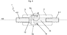
- FIG. 4 schematically shows a longitudinal section through the coupling device 1 in the coupling state.
- the male engaging portion 2 a of the male connecting part 2 is received in the coupling state of the female engaging portion 3 a of the female connecting part 3.
- the male and female connectors 2, 3 are thereby arranged coaxially along the common major axis HA, whereby the central through-holes 15, 15 'are aligned with each other and provide an unobstructed passageway for the transport or flow of fluids.
- a holding connection between the two connecting parts 2, 3 is produced in that the bulging portion 8 of the female connecting part 3 rests against the curved contact surface 11 of the male connecting part (see FIG. 5 ), where the axial force of the holding compound in the coupling state evenly distributed over the circumference of the two connecting parts 2, 3 takes place.
- a sufficient and secure hold is thus ensured in the coaxial alignment of the connecting parts 2, 3.
- FIG. 5 is the section A of FIG. 4 shown enlarged and shows a detail of the male and female engaging portions 2a, 3a engaged in the coupling state.
- the retaining connection between the two connecting parts 2, 3 is made in the coupling state that the bulge portion 8 of the female engaging portion 3a abuts the curved contact surface 11 of the annular rib 5 of the male engaging portion 2a and simultaneously the first cylindrical ring portion 7, the annular rib 5 on the nipple end portion 12 far side behind engages.
- the engaging behind the annular rib 5 through the first cylindrical ring portion 7 can also be understood as a kind of engagement of the first cylindrical ring portion 7 behind the annular rib 5.
- the engaging behind or snapping is due to the reduced compared to the outer diameter of the annular rib 5 inner diameter of the first cylindrical ring portion 7.
- the second cylindrical ring portion 9 having an inner diameter which corresponds approximately to the measured at the apex of the annular rib 5 outer diameter of the annular rib 5, is the vertex the annular rib 5 on.
- the curved bearing surface 11 of the annular rib 5 has a radius of curvature in a range of 2 mm to 4 mm and the convex curvature portion 8 in the female connector 3 has a radius of curvature in a range of 1 mm to 3 mm.
Landscapes
- Health & Medical Sciences (AREA)
- Engineering & Computer Science (AREA)
- Heart & Thoracic Surgery (AREA)
- General Engineering & Computer Science (AREA)
- Hematology (AREA)
- Biomedical Technology (AREA)
- Anesthesiology (AREA)
- Life Sciences & Earth Sciences (AREA)
- Animal Behavior & Ethology (AREA)
- General Health & Medical Sciences (AREA)
- Public Health (AREA)
- Veterinary Medicine (AREA)
- Pulmonology (AREA)
- Mechanical Engineering (AREA)
- Quick-Acting Or Multi-Walled Pipe Joints (AREA)
Description
Die Erfindung betrifft eine Kupplungsvorrichtung zum Verbinden von Schläuchen, insbesondere zahnmedizinischer Versorgungsschläuche gemäß dem Oberbegriff des Patentanspruches 1.The invention relates to a coupling device for connecting hoses, in particular dental supply hoses according to the preamble of
Für den Betrieb zahnärztlicher Instrumente, insbesondere elektrisch und/oder pneumatisch betriebener zahnärztlicher Instrumente ist es notwendig, die Instrumente mit Versorgungs- und/oder Steuereinheiten zu verbinden. Die Verbindung der Instrumente mit den Versorgungs- und Steuereinheiten erfolgt dabei über zahnmedizinische Versorgungsschläuche. Dazu sind Kupplungsvorrichtungen bekannt, die einerseits das jeweilige zahnärztliche Instrument mit einem Versorgungsschlauch als auch den Versorgungsschlauch mit einer Versorgungs- und Steuereinheit verbinden können.For the operation of dental instruments, in particular electrically and / or pneumatically operated dental instruments, it is necessary to connect the instruments with supply and / or control units. The instruments are connected to the supply and control units via dental supply hoses. For this purpose coupling devices are known, which can connect the one hand, the respective dental instrument with a supply hose and the supply hose with a supply and control unit.
Ein zahnärztliches Instrument besteht üblicherweise aus einem Handstückteil und einem darin aufgenommenen Behandlungswerkzeug, beispielsweise in Form eines Bohrers oder dergleichen. Auch wird unter einem zahnärztlichen Instrument ein vorzugsweise in Ultraschalltechnologie realisierter Zahnsteinentferner oder ein Spülinstrument verstanden. Genannte zahnärztliche Instrumente weisen in Ihrem jeweiligen Handstückteil elektrisch oder pneumatisch betriebene Motoreinheiten oder Ultraschalleinheiten auf, welche mittels des Versorgungsschlauches von der Versorgungs- und Steuereinheit mit den zum Betrieb erforderlichen Fluiden, elektrischer Energie und/oder elektrischen Steuersignalen versorgt werden.A dental instrument usually consists of a handpiece part and a treatment tool received therein, for example in the form of a drill or the like. Also, a dental instrument is understood to be a tartar remover, preferably realized in ultrasound technology, or a rinsing instrument. Said dental instruments have in their respective handpiece part electrically or pneumatically operated motor units or ultrasonic units, which are supplied by means of the supply hose from the supply and control unit with the fluids required for operation, electrical energy and / or electrical control signals.
Bei der Versorgung und Steuerung zahnmedizinischer Instrumente kann auch eine Verbindung zwischen zwei Versorgungsschläuchen oder zwischen Schlauchstücken erforderlich sein. Zum Verbinden zweier Versorgungsschläuche oder Schlauchstücke werden häufig Kupplungsvorrichtungen verwendet, die Kupplungen mittels Kegeln oder Gewinden oder so genannte Luer-Lock-Kupplungen ermöglichen. Bei derart bekannten Kupplungsvorrichtungen kann der Kupplungszustand jedoch nur hergestellt bzw. wieder gelöst werden, wenn die Kupplungsvorrichtung gut zugänglich und mit den Fingern umgreifbar ist. Das Abdrehen des einen Kupplungsteils vom anderen führt dabei auch zu einem Verdrehen oder Verdrillen der mit den Kupplungsteilen verbundenen Schlauchstücken, was in vielen Fällen sehr nachteilig ist.The supply and control of dental instruments may also require a connection between two supply tubes or between lengths of tubing. To connect two supply hoses or pieces of hose coupling devices are often used that allow couplings by means of cones or threads or so-called Luer-lock couplings. In such known coupling devices, however, the coupling state can only be made or released again when the coupling device is good accessible and can be grasped by the fingers. The twisting of a coupling part from the other also leads to a twisting or twisting of the hose pieces connected to the coupling parts, which is very disadvantageous in many cases.
Die
Zwar erfordert das Herstellen und Lösen des gekuppelten Zustandes der in der
Aufgabe der Erfindung ist es daher, eine Kupplungsvorrichtung zum Verbindung von Schläuchen, insbesondere zahnmedizinischer Versorgungsschläuche bereitzustellen, welche das Herstellen und Lösen eines Kupplungszustandes auf besonders einfache und für die Schläuche bzw. Versorgungsschläuche schonende Weise auch unter räumlich beengten Bedingungen ermöglicht. Die Aufgabe wird ausgehend von den Merkmalen des Oberbegriffes des Patentanspruches 1 durch dessen kennzeichnende Merkmale gelöst.The object of the invention is therefore to provide a coupling device for connecting hoses, especially dental supply hoses, which enables the manufacture and release of a coupling state in a particularly simple and gentle for the hoses or supply hoses, even in confined spaces. The object is achieved on the basis of the features of the preamble of
Die Erfindung betrifft eine Kupplungsvorrichtung zum Verbinden von Schläuchen, insbesondere zahnmedizinischer Versorgungsschläuche bestehend aus zumindest einem mit einem ersten Schlauchstück verbindbaren männlichen Verbindungsteil mit einem männlichen Eingriffsabschnitt und wenigstens einem mit einem zweiten Schlauchstück verbindbaren und lösbar mit dem männlichen Verbindungsteil kuppelbaren weiblichen Verbindungsteil mit einem weiblichen Eingriffsabschnitt.The invention relates to a coupling device for connecting hoses, in particular dental supply hoses consisting of at least one connectable to a first piece of hose male connector with a male engaging portion and at least one connectable to a second piece of hose and releasably coupled to the male connector female connector with a female engaging portion.
Der wesentliche Aspekt der vorliegenden Erfindung ist darin zu sehen, dass der männliche Eingriffsabschnitt zumindest eine Ringrippe mit einer gewölbten Anlagefläche und der weibliche Eingriffsabschnitt zumindest einen Wölbungsabschnitt aufweist. Im Kupplungszustand kommt es zu einem Hintergreifen der Ringrippe durch den Wölbungsabschnitt des weiblichen Eingriffsabschnittes und der Wölbungsabschnitt liegt unter Ausbildung einer haltenden Verbindung an der gewölbten Anlagefläche der Ringrippe des männlichen Eingriffsabschnittes an. Aufgrund eines Verkippens oder Verschwenkens des männlichen Verbindungsteils relativ zum weiblichen Verbindungsteil ist der Kupplungszustand durch ein Abgleiten der gewölbten Anlagefläche der Ringrippe vom Wölbungsabschnitt lösbar.The essential aspect of the present invention is to be seen in that the male engagement portion has at least one annular rib with a curved contact surface and the female engagement portion at least one bulge portion. In the coupling state, the annular rib engages behind the bulge portion of the female engagement portion, and the bulge portion abuts against the curved contact surface of the annular rib of the male engagement portion to form a retaining connection. Due to a tilting or pivoting of the male connecting part relative to the female connecting part of the coupling state can be solved by slipping the curved contact surface of the annular rib from the buckle section.
Das weibliche und männliche Verbindungsteil der erfindungsgemäßen Kupplungsvorrichtung zum Verbinden von Schläuchen, insbesondere zahnmedizinischer Versorgungsschläuche weisen je eine Längsachse und einen im Wesentlichen kreisrunden Querschnitt sowie eine zentrale Durchgangsbohrung auf. Im Kupplungszustand sind die Verbindungsteile so angeordnet, dass die Längsachsen der beiden Verbindungsteile in einer gemeinsamen Hauptachse zusammenfallen und die Durchgangsbohrungen fluchtend zueinander ausgerichtet sind. Dadurch wird sicher gestellt, dass der Transport bzw. der Fluss von Fluiden ungehindert durch die Kupplungsvorrichtung stattfinden kann. In besonders bevorzugten Ausführungsformen kann in der Kupplungsvorrichtung auch ein Ventil zum gerichteten und kontrollierten Fluss von Fluiden integriert sein.The female and male connecting part of the coupling device according to the invention for connecting hoses, in particular dental supply hoses each have a longitudinal axis and a substantially circular cross-section and a central through-bore. In the coupling state, the connecting parts are arranged so that the longitudinal axes of the two connecting parts coincide in a common main axis and the through holes are aligned with each other. This ensures that the transport or the flow of fluids can take place unhindered through the coupling device. In particularly preferred embodiments, a valve can also be integrated in the coupling device for the directed and controlled flow of fluids.
Die erfindungsgemäße Kupplungsvorrichtung, welche auch als Minischnellkupplung bezeichnet werden kann, weist geringe Außenmaße auf und eignet sich daher auch zur Verwendung unter räumlich beengten Bedingungen.The coupling device according to the invention, which can also be referred to as a mini-cross coupling, has small outer dimensions and is therefore also suitable for use in confined spaces.
Besonders vorteilhaft kann ein erstes Schlauchstück über die erfindungsgemäße Kupplungsvorrichtung in besonders einfacher Weise mit einem zweiten Schlauchstück verbunden bzw. gekoppelt werden. Das erste Schlauchstück ist dabei mit dem männlichen Verbindungsteil der Kupplungsvorrichtung und das zweite Schlauchstück mit dem weiblichen Verbindungsteil der Kupplungsvorrichtung verbunden. Durch einfaches Zusammenstecken kann der Kupplungszustand hergestellt werden, indem beide Verbindungsteile in koaxialer Ausrichtung gekuppelt werden. In diesem Kupplungszustand greifen der weibliche und männliche Eingriffsabschnitt derart ineinander, dass der Wölbungsabschnitt des weiblichen Verbindungsteiles die Ringrippe des männlichen Verbindungsteiles hintergreift. Eine haltende Verbindung zwischen beiden Verbindungsteilen wird dadurch hergestellt, dass der Wölbungsabschnitt im weiblichen Eingriffsabschnitt an der gewölbten Anlagefläche der Ringrippe im männlichen Eingriffsabschnitt anliegt. Die axiale Krafteinwirkung der haltenden Verbindung im Kupplungszustand erfolgt gleichmäßig verteilt über den Umfang der Verbindungsteile, so dass im Kupplungszustand in der koaxialen Ausrichtung der Verbindungsteile ein ausreichender und sicherer Halt gewährleistet ist.Particularly advantageously, a first piece of hose can be connected or coupled via the coupling device according to the invention in a particularly simple manner with a second piece of hose. The first piece of hose is connected to the male connection part of the coupling device and the second piece of hose connected to the female connection part of the coupling device. By simply plugging together, the coupling state be prepared by coupling both connectors in coaxial alignment. In this coupling state of the female and male engaging portion engage each other such that the bulging portion of the female connecting part engages behind the annular rib of the male connecting part. A retaining connection between the two connecting parts is produced in that the bulging portion rests in the female engaging portion on the curved contact surface of the annular rib in the male engaging portion. The axial force of the holding compound in the coupling state is uniformly distributed over the circumference of the connecting parts, so that in the coupling state in the coaxial alignment of the connecting parts a sufficient and secure grip is ensured.
Ganz besonders vorteilhaft kann der Kupplungszustand der Kupplungsvorrichtung durch Verkippen oder Verschwenken der beiden Verbindungsteile zueinander in besonders einfacher und schneller Weise gelöst werden. Durch das Verkippen ist die axiale Krafteinwirkung nicht mehr gleichmäßig verteilt über den gesamten Umfang der Verbindungsteile. An der Stelle, an der die durch das Verkippen auftretende axiale Zugkraft am größten ist, kommt es in der erfindungsgemäßen Kupplungsvorrichtung aufgrund der gewölbten Ausbildung des Wölbungsabschnittes und der gewölbten Anlagefläche zu einem Abgleiten des Wölbungsabschnittes von der gewölbten Anlagefläche der Ringrippe. Der Kupplungszustand wird gelöst und die Verbindungsteile und somit die Schlauchstücke liegen wieder getrennt vor.Very particularly advantageous, the coupling state of the coupling device can be achieved by tilting or pivoting the two connecting parts to each other in a particularly simple and fast manner. By tilting the axial force is no longer evenly distributed over the entire circumference of the connecting parts. At the point at which the axial tensile force occurring through the tilting is greatest, it comes in the coupling device according to the invention due to the curved formation of the bulge portion and the curved contact surface to a sliding of the bulge portion of the curved contact surface of the annular rib. The coupling state is released and the connecting parts and thus the hose pieces are again separated.
Ganz besondere Vorteile bringt die erfindungsgemäße Kupplungsvorrichtung mit sich, da zum Verkippen oder Verschwenken der Verbindungsteile gegeneinander keine vorgegebene Schwenk- oder Kipprichtung eingehalten werden muss, sondern das Verschwenken vielmehr in jeder Richtung möglich ist. Zudem reicht bei der erfindungsgemäßen Kupplungsvorrichtung ein kleine Schwenkbewegung aus, um den Kupplungszustand zu lösen, das heißt, die beiden Verbindungsteile müssen lediglich in eine Stellung zueinander gebracht werden, in der die beiden Längsachsen einen stumpfen Winkel einschließen, der nur geringfügig kleiner als 180° ist. Vor allem im Hinblick darauf, dass Verbindungen zwischen Versorgungsschläuchen oder Schlauchstücken unter sehr beengten räumlichen Verhältnissen, nämlich beispielsweise innerhalb eines Gehäuses einer Versorgungseinheit gelöst werden sollen, ist dies von besonderer Bedeutung.Very particular advantages brings the coupling device according to the invention, since for tilting or pivoting of the connecting parts against each other no predetermined pivoting or tilting direction must be complied with, but the pivoting is rather possible in any direction. In addition, sufficient in the coupling device according to the invention, a small pivoting movement to release the coupling state, that is, the two connecting parts must be brought to one another only in a position in which the two longitudinal axes include an obtuse angle, which is only slightly smaller than 180 ° , Especially in view of the fact that connections between supply hoses or pieces of hose under very tight spatial Conditions, namely to be solved, for example, within a housing of a supply unit, this is of particular importance.
Bevorzugt weist der weibliche Eingriffsabschnitt einen an eine Eingriffsöffnung anschließenden konischen Öffnungsabschnitt und einen an den konischen Öffnungsabschnitt anschließenden ersten zylindrischen Ringabschnitt auf. Ebenso bevorzugt ist der Wölbungsabschnitt zwischen dem an den konischen Öffnungsabschnitt anschließenden ersten zylindrischen Ringabschnitt und einem zweiten zylindrischen Ringabschnitt angeordnet. Der konische Öffnungsabschnitt, welcher die lichte Öffnungsweite ausgehend von der Eingriffsöffnung hin zum ersten zylindrischen Ringabschnitt reduziert, erleichtert das Einführen des männlichen Verbindungsteils. Die lichte Öffnungsweite und damit der Innendurchmesser des ersten zylindrischen Ringabschnittes wird mittels des Wölbungsabschnittes in Richtung des zweiten zylindrischen Ringabschnittes erweitert, so dass der zweite zylindrische Ringabschnitt einen größeren Innendurchmesser aufweist als der erste zylindrische Ringabschnitt. Durch die Anordnung des Wölbungsabschnittes zwischen dem ersten und dem zweiten zylindrischen Ringabschnitt liegt ein konvex gewölbter Übergang zwischen den zylindrischen Ringabschnitten vor, eine kantige Stufung kann dadurch vermieden werden.The female engagement section preferably has a conical opening section adjoining an engagement opening and a first cylindrical ring section adjoining the conical opening section. Also preferably, the bulge portion is disposed between the adjoining the conical opening portion first cylindrical ring portion and a second cylindrical ring portion. The conical opening portion, which reduces the clear opening width from the engagement opening toward the first cylindrical ring portion, facilitates insertion of the male connection part. The clear opening width and thus the inner diameter of the first cylindrical ring portion is widened by means of the bulge portion in the direction of the second cylindrical ring portion, so that the second cylindrical ring portion has a larger inner diameter than the first cylindrical ring portion. Due to the arrangement of the curvature portion between the first and second cylindrical ring portion is a convexly curved transition between the cylindrical ring sections, an edged gradation can be avoided.
Die Anordnung des Wölbungsabschnittes zwischen dem ersten und dem zweiten zylindrischen Ringabschnitt führt im Kupplungszustand zu einem Hintergreifen der Ringrippe des männlichen Verbindungsteils durch den ersten zylindrischen Ringabschnitt. Dieses Hintergreifen der Ringrippe kann auch als eine Art Einrasten des ersten zylindrischen Ringabschnittes hinter der Ringrippe verstanden werden. Das Hintergreifen bzw. Einrasten erfolgt aufgrund des im Vergleich zum Außendurchmesser der Ringrippe verkleinerten Innendurchmessers des ersten zylindrischen Ringabschnittes. Der zweite zylindrische Ringabschnitt mit einem Innendurchmesser, der in etwa dem am Scheitelpunkt der Ringrippe gemessenen Außendurchmesser der Ringrippe entspricht, liegt im Kupplungszustand dem Scheitelpunkt der Ringrippe an. Durch das beschriebene gegenseitige Ineinandergreifen bzw. durch das Anliegen oder Anlagern der genannten Abschnitte des männlichen und weiblichen Eingriffsabschnittes wird eine dichtende Verbindung zwischen den beiden Verbindungsteilen hergestellt.The arrangement of the bulge portion between the first and second cylindrical ring portion leads in the coupling state to engage behind the annular rib of the male connection part by the first cylindrical ring portion. This engaging behind the annular rib can also be understood as a kind of engagement of the first cylindrical ring portion behind the annular rib. The engaging behind or latching takes place due to the smaller compared to the outer diameter of the annular rib inner diameter of the first cylindrical ring portion. The second cylindrical ring portion with an inner diameter which corresponds approximately to the measured at the apex of the annular rib outer diameter of the annular rib, is in the coupling state to the vertex of the annular rib. By the described mutual interlocking or by the concern or attaching said sections the male and female engagement portion a sealing connection between the two connecting parts is made.
Gemäß einer bevorzugten Ausführungsform der vorliegenden Erfindung weist der weibliche Eingriffsabschnitt zusätzlich einen zylindrischen Basisabschnitt auf, wobei der zylindrische Basisabschnitt unter Ausbildung einer Schulter an den zweiten zylindrischen Ringabschnitt anschließt. Der Innendurchmesser des zylindrischen Basisabschnittes ist dabei größer als diejenige des zweiten zylindrischen Ringabschnittes.According to a preferred embodiment of the present invention, the female engagement portion additionally comprises a cylindrical base portion, the cylindrical base portion joining the second cylindrical ring portion to form a shoulder. The inner diameter of the cylindrical base portion is larger than that of the second cylindrical ring portion.
Besondere Vorteile ergeben sich dadurch dass der männliche Eingriffsabschnitt einen gerundeten Nippelendabschnitt aufweist und dass die Ringrippe auf der dem Nippelendabschnitt zugewandten Seite eine Einführwölbung zum erleichterten gleitenden Einführen in den weiblichen Eingriffsabschnitt aufweist. Die Einführwölbung der Ringrippe liegt der gewölbten Anlagefläche gegenüber und weist bevorzugt einen Krümmungsradius in einem Bereich von 4 mm bis 6 mm auf. Besonders bevorzugt weist die gewölbte Anlagefläche der Ringrippe einen Krümmungsradius in einem Bereich von 2 mm bis 4 mm auf.Particular advantages result from the fact that the male engagement portion has a rounded Nippelendabschnitt and that the annular rib on the nipple end portion facing side has an insertion curvature for facilitating sliding insertion into the female engagement portion. The introduction curvature of the annular rib is opposite to the curved contact surface and preferably has a radius of curvature in a range of 4 mm to 6 mm. Particularly preferably, the curved contact surface of the annular rib has a radius of curvature in a range of 2 mm to 4 mm.
Vorteilhaft weist das männliche Verbindungsteil im Bereich des männlichen Eingriffsabschnittes zusätzlich eine umlaufende Ringnute zur Aufnahme eines Dichtungselementes auf, wobei die Ringnute auf der dem Nippelendabschnitt abgewandten Seite an die Ringrippe anschließt. Durch ein in die Ringnute eingelegtes Dichtungselement kann die Kupplungsvorrichtung zusätzlich abgedichtet werden, so dass für die zu verbindenden Versorgungsschläuche sicher gestellt ist, dass beim Transport von Fluiden keine Leckstellen innerhalb der Kupplungsvorrichtung auftreten. Als Dichtungselemente können beispielsweise Dichtungsringe aus Gummi oder Kunststoff, insbesondere O-Ringe verwendet werden.Advantageously, the male connection part in the region of the male engagement section additionally has a circumferential annular groove for receiving a sealing element, wherein the annular groove adjoins the annular rib on the side remote from the nipple end section. By a inserted into the annular groove sealing element, the coupling device can be additionally sealed so that it is ensured for the supply hoses to be connected that occur during the transport of fluids no leaks within the coupling device. As sealing elements, for example, sealing rings made of rubber or plastic, in particular O-rings can be used.
Bevorzugt weist der Wölbungsabschnitt des weiblichen Eingriffsabschnittes eine konvexe Wölbung mit einem Krümmungsradius in einem Bereich von 1 mm bis 3 mm auf.Preferably, the bulging portion of the female engaging portion has a convex curvature with a radius of curvature in a range of 1 mm to 3 mm.
Gemäß einer besonders bevorzugten Ausführungsform der vorliegenden Erfindung sind zur Verbindung des männlichen Verbindungsteils mit einem ersten Schlauchstück und zur Verbindung des weiblichen Verbindungsteils mit einem zweiten Schlauchstück gerade Schlauchverbinder vorgesehen. Beispielsweise können die Schlauchverbinder aus Kunststoff oder aus Metall, insbesondere aus Messing hergestellt sein.According to a particularly preferred embodiment of the present invention straight hose connector are provided for connecting the male connection part with a first piece of tubing and for connecting the female connection part with a second piece of tubing. For example, the hose connector can be made of plastic or metal, in particular brass.
Besonders bevorzugt sind das männliche und weibliche Verbindungsteil aus einem Kunststoff, insbesondere aus einem thermoplastischen Kunststoff, beispielsweise aus Polypropylen hergestellt.Particularly preferably, the male and female connecting part made of a plastic, in particular made of a thermoplastic material, for example made of polypropylene.
Die Erfindung soll nachfolgend anhand von Ausführungsbeispielen im Zusammenhang mit den Figuren näher erläutert werden. Zudem ergeben sich Weiterbildungen, Vorteile und Anwendungsmöglichkeiten der Erfindung auch aus der nachfolgenden Beschreibung der Ausführungsbeispiele und aus den Figuren. Dabei sind alle beschriebenen und/oder bildlich dargestellten Merkmale für sich oder in beliebiger Kombination grundsätzlich Gegenstand der Erfindung, unabhängig von ihrer Zusammenfassung in den Ansprüchen oder deren Rückbeziehung. Auch wird der Inhalt der Ansprüche zu einem Bestandteil der Beschreibung gemacht.The invention will be explained in more detail by means of embodiments in conjunction with the figures. In addition, developments, advantages and applications of the invention also result from the following description of the embodiments and from the figures. In this case, all described and / or illustrated features alone or in any combination are fundamentally the subject of the invention, regardless of their summary in the claims or their dependency. Also, the content of the claims is made an integral part of the description.
Es wird aber ausdrücklich darauf hingewiesen, dass die Erfindung keinesfalls auf die angegebenen Beispiele beschränkt sein soll. Es zeigen
- Fig. 1
- schematisch dargestellt eine Kupplungsvorrichtung gemäß der vorliegenden Erfindung in seitlicher Ansicht,
- Fig. 2
- eine Längsschnittdarstellung eines männlichen Verbindungsteils,
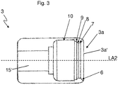
- Fig. 3
- eine Längsschnittdarstellung eines weiblichen Verbindungsteils,
- Fig. 4
- schematisch dargestellt einen Längsschnitt durch die
Kupplungsvorrichtung der Figur 1 und - Fig. 5
- den Ausschnitt A der
Figur 4 in vergrößerter Darstellung.
- Fig. 1
- schematically shown a coupling device according to the present invention in a side view,
- Fig. 2
- a longitudinal sectional view of a male connecting part,
- Fig. 3
- a longitudinal sectional view of a female connecting part,
- Fig. 4
- schematically illustrated a longitudinal section through the coupling device of
FIG. 1 and - Fig. 5
- the section A of
FIG. 4 in an enlarged view.
In der
Die Kupplungsvorrichtung 1 besteht aus einem mit einem ersten Schlauchstück verbindbaren männlichen Verbindungsteil 2 und einem mit einem zweiten Schlauchstück verbindbaren und lösbar mit dem männlichen Verbindungsteil 2 kuppelbaren weiblichen Verbindungsteil 3. Im dargestellten Beispiel sind zur Verbindung der Schlauchstücke mit den beiden Verbindungsteilen 2, 3 zwei gerade Schlauchverbinder 4.1, 4.2 vorgesehen. Bei den Schlauchverbindern 4.1, 4.2 handelt es sich beispielsweise um einfache Steckverbinder, welche an den den Kupplungsseiten abgewandten Enden des männlichen und weiblichen Verbindungsteils 2,3 eingesteckt sind und zum Aufstecken von Schlauchstücken ausgebildet sind.The
Das weibliche und männliche Verbindungsteil 2, 3 der erfindungsgemäßen Kupplungsvorrichtung 1 zum Verbinden von Schläuchen, insbesondere zahnmedizinischer Versorgungsschläuche weisen einen im Wesentlichen kreisrunden Querschnitt mit einem jeweiligen Außendurchmesser in einem Bereich von 6 mm bis 7 mm auf. Im Kupplungszustand sind die Verbindungsteile so angeordnet, dass Längsachsen LA1, LA2 (in der
In den
Der am Scheitelpunkt der Ringrippe 5 gemessene Außendurchmesser der Ringrippe 5 ist etwa 1,2fach bis 1,4fach größer als der Außendurchmesser des Nippelendabschnittes 12, welcher in einem Bereich von rund 4 mm bis 4,5 mm liegt.The measured at the apex of the
Im dargestellten Beispiel schließt sich der Ringrippe 5 auf der dem Nippelendabschnitt 12 abgewandten Seite eine umlaufende Ringnute 13 zur Aufnahme eines Dichtungselementes 16 (in der
Das in
Im dargestellten Beispiel ist der Wölbungsabschnitt 8 zwischen einem ersten zylindrischen Ringabschnitt 7 und einem zweiten zylindrischen Ringabschnitt 9 angeordnet, wobei der Innendurchmesser des ersten zylindrischen Ringabschnittes 7 mit rund 4,9 mm bis 5,3 mm kleiner ist als der Innendurchmesser des zweiten zylindrischen Ringabschnittes 9. Zur Eingriffsöffnung 3a' hin schließt sich dem ersten zylindrischen Ringabschnitt 7 ein konischer Öffnungsabschnitt 6 an, welcher ein erleichtertes Einführen des männlichen Verbindungsteils 2 in das weibliche Verbindungsteil 3 sicher stellt. Auf der der Eingriffsöffnung 3a' abgewandten Seite schließt sich an den zweiten zylindrischen Ringabschnitt 9 ein zylindrischer Basisabschnitt 10 an, in welchem im Kupplungszustand der Nippelendabschnitt 12 des männlichen Verbindungsteils 2 aufgenommen ist.In the example shown, the curvature section 8 is arranged between a first cylindrical ring section 7 and a second cylindrical ring section 9, the inside diameter of the first cylindrical ring section 7 being approximately 4.9 mm to 5.3 mm smaller than the inside diameter of the second cylindrical ring section 9 To the
Ausgehend von der Eingriffsöffnung 3a' des weiblichen Eingriffsabschnittes 3a schließen somit in axialer Richtung der Reihe nach der konische Öffnungsabschnitt 6, der erste zylindrische Ringabschnitt 7, der Wölbungsabschnitt 8, der zweite zylindrische Ringabschnitt 9 und der zylindrischer Basisabschnitt 10 aneinander an. Diese Aufeinanderfolge der genannten Abschnitte des weiblichen Eingriffsabschnittes 3a in Kombination mit der wie oben beschriebenen Ausbildung des männlichen Eingriffsabschnittes 2a ermöglicht sowohl ein einfaches Verbinden wie auch ein einfaches Trennen des männlichen und weiblichen Verbindungsteils 2, 3.Starting from the
Die
In der
Zum Lösen des Kupplungszustandes bzw. zum Trennen der Verbindung des männlichen und weiblichen Verbindungsteils 2, 3 ist lediglich ein Verkippen oder Verschwenken der beiden Verbindungsteile 2, 3 notwendig. Durch das Verkippen oder Verschwenken des männlichen Verbindungsteils 2 relativ zum weiblichen Verbindungsteil 3 ist die axiale Krafteinwirkung nicht mehr gleichmäßig verteilt über den gesamten Umfang der beiden Verbindungsteile 2, 3. An der Stelle, an der die durch das Verkippen auftretende axiale Zugkraft am größten ist, kommt es in der erfindungsgemäßen Kupplungsvorrichtung 1 zu einem Abgleiten des konvexen Wölbungsabschnittes 8 von der gewölbten Anlagefläche 11 der Ringrippe 5 und der Kupplungszustand wird gelöst. Im dargestellten Beispiel weist die gewölbte Anlagefläche 11 der Ringrippe 5 einen Krümmungsradius in einem Bereich von 2 mm bis 4 mm und der konvexe Wölbungsabschnitt 8 im weiblichen Verbindungsteil 3 einen Krümmungsradius in einem Bereich von 1 mm bis 3 mm auf.To release the coupling state or to disconnect the connection of the male and
Die Erfindung wurde voranstehend an einem Ausführungsbeispiel beschrieben. Es versteht sich, dass zahlreiche Modifikationen und Änderungen der Erfindung möglich sind im Bereich der Ansprüche.The invention has been described above by means of an embodiment. It is understood that numerous modifications and variations of the invention are possible within the scope of the claims.
- 11
- Kupplungsvorrichtungcoupling device
- 22
- männliches Verbindungsteilmale connection part
- 2a2a
- männlicher Eingriffsabschnittmale engaging section
- 33
- weibliches Verbindungsteilfemale connector
- 3a3a
- weiblicher Eingriffsabschnittfemale engaging section
- 3a'3a '
- Eingriffsöffnungengagement opening
- 4.1, 4.24.1, 4.2
- Schlauchverbinderhose connector
- 55
- Ringrippeannular rib
- 66
- konischer Öffnungsabschnittconical opening section
- 77
- erster zylindrischer Ringabschnittfirst cylindrical ring section
- 88th
- Wölbungsabschnittbulge portion
- 99
- zweiter zylindrischer Ringabschnittsecond cylindrical ring section
- 1010
- zylindrischer Basisabschnittcylindrical base section
- 1111
- gewölbte Anlageflächecurved contact surface
- 1212
- NippelendabschnittNippelendabschnitt
- 1313
- Ringnuteannular groove
- 1414
- EinführwölbungEinführwölbung
- 15, 15'15, 15 '
- zentrale Durchgangsbohrungcentral through-hole
- 1616
- Dichtungselementsealing element
- LA1LA1
- Längsachselongitudinal axis
- LA2LA2
- Längsachselongitudinal axis
- HAHA
- Hauptachsemain axis
Claims (9)
- Coupling device (1) for connecting hoses, particularly dental supply hoses, consisting of at least one male connector part (2) that has a male engagement section (2a) and can be connected to a first hose section and at least one female connector part (3) that has a female engagement section (3a) and can be connected to a second hose section, and that can detachably be coupled to the male connector part (2), wherein the male engagement section (2a) comprises at least one annular rib (5) having a curved contact surface (11) and the female engagement section (3a) comprises at least one curvature section (8), characterized in that the curvature section (8) of the female engagement section (3a) engages in the coupled state behind the annular rib (5) of the male engagement section (2a) and abuts against the curved contact surface (11) of the annular rib (5) such that a retentive connection is formed, wherein the female engagement section (3a) comprises a conical opening section (6) adjacent to an engagement opening (3a') and a first cylindrical ring section (7) adjacent to the conical opening section (6), wherein the curvature section (8) has a convex curvature and is arranged between the first cylindrical ring section (7) and a second cylindrical ring section (9), and wherein the coupled state can be disengaged by tilting or pivoting the male connector part (2) relative to the female connector part (3) and thereby causing the curved contact surface (11) of the annular rib (5) to slide off the curvature section (8).
- Coupling device (1) according to claim 1, characterized in that the female engagement section (3a) additionally comprises a cylindrical base section (10), wherein the cylindrical base section (10) adjoins the second cylindrical ring section (9) such that a shoulder is formed.
- Coupling device (1) according to claim 1 or 2, characterized in that the male engagement section (2a) comprises a rounded nipple end section (12).
- Coupling device (1) according to one of claims 1 to 3, characterized in that the annular rib (5) comprises on the side facing the nipple end section (12) an insertion curvature (14) for the sliding insertion into the female engagement section (3a), wherein the insertion curvature (14) lies opposite of the curved contact surface (11) of the annular rib (5) and has a curvature radius in the range of 4 mm to 6 mm.
- Coupling device (1) according to one of the preceding claims, characterized in that the curved contact surface (11) of the annular rib (5) has a curvature radius in the range of 2 mm to 4 mm.
- Coupling device (1) according to one of the preceding claims, characterized in that the male connector part (2) additionally features a circumferential annular groove (13) for accommodating a sealing element (16) in the region of the male engagement section (2a), wherein the annular groove (13) is arranged adjacent to the annular rib (5) on the side facing away from the nipple end section (12).
- Coupling device (1) according to one of the preceding claims, characterized in that the curvature section (8) of the female engagement section (3a) has a convex curvature with a curvature radius in the range of 1 mm to 3 mm.
- Coupling device (1) according to one of the preceding claims, characterized in that straight hose connectors (4.1, 4.2) are provided for connecting the male connector part (2) to a first hose section and for connecting the female connector part (3) to a second hose section.
- Coupling device (1) according to one of the preceding claims, characterized in that the male and the female connector part (2, 3) are made of plastic, particularly a thermoplastic polymer such as polypropylene.
Applications Claiming Priority (1)
| Application Number | Priority Date | Filing Date | Title |
|---|---|---|---|
| DE102013105611.3A DE102013105611B4 (en) | 2013-05-31 | 2013-05-31 | Coupling device for connecting hoses |
Publications (2)
| Publication Number | Publication Date |
|---|---|
| EP2808052A1 EP2808052A1 (en) | 2014-12-03 |
| EP2808052B1 true EP2808052B1 (en) | 2017-02-22 |
Family
ID=50513704
Family Applications (1)
| Application Number | Title | Priority Date | Filing Date |
|---|---|---|---|
| EP14164764.4A Active EP2808052B1 (en) | 2013-05-31 | 2014-04-15 | Coupling device for connecting hoses, in particular dental supply hoses |
Country Status (3)
| Country | Link |
|---|---|
| US (1) | US9664320B2 (en) |
| EP (1) | EP2808052B1 (en) |
| DE (1) | DE102013105611B4 (en) |
Cited By (1)
| Publication number | Priority date | Publication date | Assignee | Title |
|---|---|---|---|---|
| US11707418B2 (en) | 2019-05-20 | 2023-07-25 | Metis Design Bv | Connector for a gastrostomy device |
Families Citing this family (3)
| Publication number | Priority date | Publication date | Assignee | Title |
|---|---|---|---|---|
| US9937017B2 (en) * | 2015-03-06 | 2018-04-10 | Dentsply Sirona Inc. | Dental handpiece |
| EP3318293A1 (en) * | 2016-11-04 | 2018-05-09 | Berlin Heart GmbH | System for securing a releasable connection between two elements |
| EP4306154A3 (en) * | 2016-11-23 | 2024-03-06 | Fisher & Paykel Healthcare Limited | High flow luer connector |
Family Cites Families (19)
| Publication number | Priority date | Publication date | Assignee | Title |
|---|---|---|---|---|
| DE19637C (en) | H. MESTERN in Berlin | Innovation in the water jet fan patented under No. 13492 | ||
| US3667785A (en) * | 1970-05-20 | 1972-06-06 | Martin Kapeker | Coupler for tubular members |
| US3990727A (en) * | 1976-01-26 | 1976-11-09 | Stephen Franics Gallagher | Quick detachable coupler |
| US4030850A (en) * | 1976-08-02 | 1977-06-21 | The United States Of America As Represented By The Secretary Of The Army | Interlocked joint |
| JPH0435670Y2 (en) * | 1985-05-30 | 1992-08-24 | ||
| DE4322868A1 (en) * | 1993-07-09 | 1995-01-12 | Sterimed Gmbh | Bayonet hose connector |
| US5797627A (en) * | 1995-02-28 | 1998-08-25 | Salter Labs | Swivel |
| US5549583A (en) * | 1995-08-04 | 1996-08-27 | Adam Spence Corporation | Surgical connector |
| DE19637266C1 (en) * | 1996-09-13 | 1997-12-04 | Wolf Gmbh Richard | Coupling for connecting hose to medical instrument, apparatus or with another hose |
| FR2824620B1 (en) * | 2001-05-10 | 2004-09-24 | Air Liquide | VALVE-REGULATOR PROVIDED WITH A CONNECTION SUITABLE FOR CONNECTING A USER SOCKET |
| US6854771B1 (en) * | 2002-05-10 | 2005-02-15 | Eaton Corporation | Low pressure fitting |
| US7681927B2 (en) * | 2002-05-10 | 2010-03-23 | Eaton Corporation | Low pressure fitting |
| US20050143714A1 (en) * | 2003-09-26 | 2005-06-30 | Medtronic, Inc. | Sutureless pump connector |
| US7811278B2 (en) * | 2007-02-11 | 2010-10-12 | Cuffco, Llc | Fluid connector |
| DE102009016373A1 (en) * | 2009-04-07 | 2010-10-21 | V. KRÜTTEN MEDIZINISCHE EINMALGERÄTE GmbH | Connector for the probe tube of an enteral feeding tube and assembly of an enteral feeding tube and an enteral transfer system |
| CN108295373B (en) * | 2011-09-09 | 2021-04-27 | Icu医学有限公司 | Medical connector with flow-resistant mating interface |
| DE102011084027A1 (en) * | 2011-10-05 | 2013-04-11 | Maquet Cardiopulmonary Ag | Quick coupling device |
| US8961394B2 (en) * | 2011-12-20 | 2015-02-24 | Apollo Endosurgery, Inc. | Self-sealing fluid joint for use with a gastric band |
| US20130164706A1 (en) * | 2011-12-23 | 2013-06-27 | Gsn Products, Inc. | Adjustable suction tips for dental and medical uses |
-
2013
- 2013-05-31 DE DE102013105611.3A patent/DE102013105611B4/en not_active Expired - Fee Related
-
2014
- 2014-04-15 EP EP14164764.4A patent/EP2808052B1/en active Active
- 2014-05-20 US US14/282,438 patent/US9664320B2/en active Active
Cited By (1)
| Publication number | Priority date | Publication date | Assignee | Title |
|---|---|---|---|---|
| US11707418B2 (en) | 2019-05-20 | 2023-07-25 | Metis Design Bv | Connector for a gastrostomy device |
Also Published As
| Publication number | Publication date |
|---|---|
| US20140353966A1 (en) | 2014-12-04 |
| DE102013105611B4 (en) | 2016-12-01 |
| EP2808052A1 (en) | 2014-12-03 |
| US9664320B2 (en) | 2017-05-30 |
| DE102013105611A1 (en) | 2014-12-04 |
Similar Documents
| Publication | Publication Date | Title |
|---|---|---|
| DE69212793T2 (en) | Connecting device for parts of a fluid distribution system, said parts and system | |
| EP2964992B1 (en) | Plug-in connection for two pipes and method for assembling the plug-in connection | |
| DE2200440A1 (en) | Hose coupling | |
| EP2808052B1 (en) | Coupling device for connecting hoses, in particular dental supply hoses | |
| EP3244962B1 (en) | Connection device for a medical fluid conduit system | |
| WO2001061223A1 (en) | Rotatable stopcock for a male coupling having a 90° offset connecting piece | |
| EP3117868A1 (en) | Connection device for wound care and wound care kit | |
| DE60020212T2 (en) | PIPE CONNECTING ELEMENT, ESPECIALLY FOR PLASTIC PIPES | |
| EP3322923B1 (en) | Sanitary line attachment | |
| EP2325538A1 (en) | Device with at least one hollow element for conveying a fluid and with a connection element | |
| EP1457607B1 (en) | Faucet comprising a device for fixing a pipe | |
| EP4138625B1 (en) | Medical device | |
| DE202015104332U1 (en) | hose coupling | |
| DE202004014828U1 (en) | Endoscopic instrument | |
| EP3875056B1 (en) | Method and system for the treatment and / or care of a medical or dental instrument | |
| DE102012210837A1 (en) | trocar | |
| EP3153757B1 (en) | Detachable plug connection for pipes | |
| DE102008021312B4 (en) | Device for releasable connection with one end of a tubular conduit, in particular with a rigid tube | |
| EP2975311B1 (en) | Screw coupling for hoses | |
| EP3104928A1 (en) | Device for connecting medical disposable articles in a sterile manner | |
| EP4001724B1 (en) | Connecting device for media-carrying components | |
| DE102021132893B3 (en) | Connection system for connecting a fluid line to a fluid system | |
| DE102010034475B4 (en) | Device for connecting to one end of a tubular conduit | |
| EP3488973A1 (en) | Change jaw for a press tool | |
| WO2024042039A1 (en) | Fluid coupling, method for producing a fluid coupling, and fluid coupling arrangement |
Legal Events
| Date | Code | Title | Description |
|---|---|---|---|
| PUAI | Public reference made under article 153(3) epc to a published international application that has entered the european phase |
Free format text: ORIGINAL CODE: 0009012 |
|
| 17P | Request for examination filed |
Effective date: 20140415 |
|
| AK | Designated contracting states |
Kind code of ref document: A1 Designated state(s): AL AT BE BG CH CY CZ DE DK EE ES FI FR GB GR HR HU IE IS IT LI LT LU LV MC MK MT NL NO PL PT RO RS SE SI SK SM TR |
|
| AX | Request for extension of the european patent |
Extension state: BA ME |
|
| R17P | Request for examination filed (corrected) |
Effective date: 20150423 |
|
| RBV | Designated contracting states (corrected) |
Designated state(s): AL AT BE BG CH CY CZ DE DK EE ES FI FR GB GR HR HU IE IS IT LI LT LU LV MC MK MT NL NO PL PT RO RS SE SI SK SM TR |
|
| RAP1 | Party data changed (applicant data changed or rights of an application transferred) |
Owner name: MEDTRONIC MEDIZINISCH-ELEKTRONISCHE GERAETE-GESELL |
|
| RIC1 | Information provided on ipc code assigned before grant |
Ipc: A61M 39/00 20060101ALN20160810BHEP Ipc: A61M 39/10 20060101AFI20160810BHEP |
|
| GRAP | Despatch of communication of intention to grant a patent |
Free format text: ORIGINAL CODE: EPIDOSNIGR1 |
|
| INTG | Intention to grant announced |
Effective date: 20160921 |
|
| GRAS | Grant fee paid |
Free format text: ORIGINAL CODE: EPIDOSNIGR3 |
|
| STAA | Information on the status of an ep patent application or granted ep patent |
Free format text: STATUS: GRANT OF PATENT IS INTENDED |
|
| GRAJ | Information related to disapproval of communication of intention to grant by the applicant or resumption of examination proceedings by the epo deleted |
Free format text: ORIGINAL CODE: EPIDOSDIGR1 |
|
| GRAL | Information related to payment of fee for publishing/printing deleted |
Free format text: ORIGINAL CODE: EPIDOSDIGR3 |
|
| STAA | Information on the status of an ep patent application or granted ep patent |
Free format text: STATUS: REQUEST FOR EXAMINATION WAS MADE |
|
| INTC | Intention to grant announced (deleted) | ||
| GRAR | Information related to intention to grant a patent recorded |
Free format text: ORIGINAL CODE: EPIDOSNIGR71 |
|
| STAA | Information on the status of an ep patent application or granted ep patent |
Free format text: STATUS: GRANT OF PATENT IS INTENDED |
|
| GRAA | (expected) grant |
Free format text: ORIGINAL CODE: 0009210 |
|
| STAA | Information on the status of an ep patent application or granted ep patent |
Free format text: STATUS: THE PATENT HAS BEEN GRANTED |
|
| RIC1 | Information provided on ipc code assigned before grant |
Ipc: A61M 39/10 20060101AFI20161220BHEP Ipc: A61M 39/00 20060101ALN20161220BHEP |
|
| AK | Designated contracting states |
Kind code of ref document: B1 Designated state(s): AL AT BE BG CH CY CZ DE DK EE ES FI FR GB GR HR HU IE IS IT LI LT LU LV MC MK MT NL NO PL PT RO RS SE SI SK SM TR |
|
| INTG | Intention to grant announced |
Effective date: 20170117 |
|
| REG | Reference to a national code |
Ref country code: GB Ref legal event code: FG4D Free format text: NOT ENGLISH |
|
| REG | Reference to a national code |
Ref country code: CH Ref legal event code: EP |
|
| REG | Reference to a national code |
Ref country code: AT Ref legal event code: REF Ref document number: 868795 Country of ref document: AT Kind code of ref document: T Effective date: 20170315 |
|
| REG | Reference to a national code |
Ref country code: IE Ref legal event code: FG4D Free format text: LANGUAGE OF EP DOCUMENT: GERMAN |
|
| REG | Reference to a national code |
Ref country code: DE Ref legal event code: R096 Ref document number: 502014002738 Country of ref document: DE |
|
| REG | Reference to a national code |
Ref country code: FR Ref legal event code: PLFP Year of fee payment: 4 |
|
| REG | Reference to a national code |
Ref country code: LT Ref legal event code: MG4D |
|
| REG | Reference to a national code |
Ref country code: NL Ref legal event code: MP Effective date: 20170222 |
|
| PG25 | Lapsed in a contracting state [announced via postgrant information from national office to epo] |
Ref country code: NO Free format text: LAPSE BECAUSE OF FAILURE TO SUBMIT A TRANSLATION OF THE DESCRIPTION OR TO PAY THE FEE WITHIN THE PRESCRIBED TIME-LIMIT Effective date: 20170522 Ref country code: HR Free format text: LAPSE BECAUSE OF FAILURE TO SUBMIT A TRANSLATION OF THE DESCRIPTION OR TO PAY THE FEE WITHIN THE PRESCRIBED TIME-LIMIT Effective date: 20170222 Ref country code: GR Free format text: LAPSE BECAUSE OF FAILURE TO SUBMIT A TRANSLATION OF THE DESCRIPTION OR TO PAY THE FEE WITHIN THE PRESCRIBED TIME-LIMIT Effective date: 20170523 Ref country code: FI Free format text: LAPSE BECAUSE OF FAILURE TO SUBMIT A TRANSLATION OF THE DESCRIPTION OR TO PAY THE FEE WITHIN THE PRESCRIBED TIME-LIMIT Effective date: 20170222 Ref country code: LT Free format text: LAPSE BECAUSE OF FAILURE TO SUBMIT A TRANSLATION OF THE DESCRIPTION OR TO PAY THE FEE WITHIN THE PRESCRIBED TIME-LIMIT Effective date: 20170222 |
|
| PG25 | Lapsed in a contracting state [announced via postgrant information from national office to epo] |
Ref country code: BG Free format text: LAPSE BECAUSE OF FAILURE TO SUBMIT A TRANSLATION OF THE DESCRIPTION OR TO PAY THE FEE WITHIN THE PRESCRIBED TIME-LIMIT Effective date: 20170522 Ref country code: NL Free format text: LAPSE BECAUSE OF FAILURE TO SUBMIT A TRANSLATION OF THE DESCRIPTION OR TO PAY THE FEE WITHIN THE PRESCRIBED TIME-LIMIT Effective date: 20170222 Ref country code: SE Free format text: LAPSE BECAUSE OF FAILURE TO SUBMIT A TRANSLATION OF THE DESCRIPTION OR TO PAY THE FEE WITHIN THE PRESCRIBED TIME-LIMIT Effective date: 20170222 Ref country code: PT Free format text: LAPSE BECAUSE OF FAILURE TO SUBMIT A TRANSLATION OF THE DESCRIPTION OR TO PAY THE FEE WITHIN THE PRESCRIBED TIME-LIMIT Effective date: 20170622 Ref country code: RS Free format text: LAPSE BECAUSE OF FAILURE TO SUBMIT A TRANSLATION OF THE DESCRIPTION OR TO PAY THE FEE WITHIN THE PRESCRIBED TIME-LIMIT Effective date: 20170222 Ref country code: ES Free format text: LAPSE BECAUSE OF FAILURE TO SUBMIT A TRANSLATION OF THE DESCRIPTION OR TO PAY THE FEE WITHIN THE PRESCRIBED TIME-LIMIT Effective date: 20170222 Ref country code: LV Free format text: LAPSE BECAUSE OF FAILURE TO SUBMIT A TRANSLATION OF THE DESCRIPTION OR TO PAY THE FEE WITHIN THE PRESCRIBED TIME-LIMIT Effective date: 20170222 |
|
| PG25 | Lapsed in a contracting state [announced via postgrant information from national office to epo] |
Ref country code: IT Free format text: LAPSE BECAUSE OF FAILURE TO SUBMIT A TRANSLATION OF THE DESCRIPTION OR TO PAY THE FEE WITHIN THE PRESCRIBED TIME-LIMIT Effective date: 20170222 Ref country code: SK Free format text: LAPSE BECAUSE OF FAILURE TO SUBMIT A TRANSLATION OF THE DESCRIPTION OR TO PAY THE FEE WITHIN THE PRESCRIBED TIME-LIMIT Effective date: 20170222 Ref country code: EE Free format text: LAPSE BECAUSE OF FAILURE TO SUBMIT A TRANSLATION OF THE DESCRIPTION OR TO PAY THE FEE WITHIN THE PRESCRIBED TIME-LIMIT Effective date: 20170222 Ref country code: RO Free format text: LAPSE BECAUSE OF FAILURE TO SUBMIT A TRANSLATION OF THE DESCRIPTION OR TO PAY THE FEE WITHIN THE PRESCRIBED TIME-LIMIT Effective date: 20170222 Ref country code: CZ Free format text: LAPSE BECAUSE OF FAILURE TO SUBMIT A TRANSLATION OF THE DESCRIPTION OR TO PAY THE FEE WITHIN THE PRESCRIBED TIME-LIMIT Effective date: 20170222 |
|
| REG | Reference to a national code |
Ref country code: DE Ref legal event code: R097 Ref document number: 502014002738 Country of ref document: DE |
|
| PG25 | Lapsed in a contracting state [announced via postgrant information from national office to epo] |
Ref country code: PL Free format text: LAPSE BECAUSE OF FAILURE TO SUBMIT A TRANSLATION OF THE DESCRIPTION OR TO PAY THE FEE WITHIN THE PRESCRIBED TIME-LIMIT Effective date: 20170222 Ref country code: DK Free format text: LAPSE BECAUSE OF FAILURE TO SUBMIT A TRANSLATION OF THE DESCRIPTION OR TO PAY THE FEE WITHIN THE PRESCRIBED TIME-LIMIT Effective date: 20170222 Ref country code: SM Free format text: LAPSE BECAUSE OF FAILURE TO SUBMIT A TRANSLATION OF THE DESCRIPTION OR TO PAY THE FEE WITHIN THE PRESCRIBED TIME-LIMIT Effective date: 20170222 |
|
| REG | Reference to a national code |
Ref country code: CH Ref legal event code: PL |
|
| PLBE | No opposition filed within time limit |
Free format text: ORIGINAL CODE: 0009261 |
|
| STAA | Information on the status of an ep patent application or granted ep patent |
Free format text: STATUS: NO OPPOSITION FILED WITHIN TIME LIMIT |
|
| REG | Reference to a national code |
Ref country code: IE Ref legal event code: MM4A |
|
| 26N | No opposition filed |
Effective date: 20171123 |
|
| PG25 | Lapsed in a contracting state [announced via postgrant information from national office to epo] |
Ref country code: MC Free format text: LAPSE BECAUSE OF FAILURE TO SUBMIT A TRANSLATION OF THE DESCRIPTION OR TO PAY THE FEE WITHIN THE PRESCRIBED TIME-LIMIT Effective date: 20170222 |
|
| PG25 | Lapsed in a contracting state [announced via postgrant information from national office to epo] |
Ref country code: LU Free format text: LAPSE BECAUSE OF NON-PAYMENT OF DUE FEES Effective date: 20170415 Ref country code: SI Free format text: LAPSE BECAUSE OF FAILURE TO SUBMIT A TRANSLATION OF THE DESCRIPTION OR TO PAY THE FEE WITHIN THE PRESCRIBED TIME-LIMIT Effective date: 20170222 Ref country code: LI Free format text: LAPSE BECAUSE OF NON-PAYMENT OF DUE FEES Effective date: 20170430 Ref country code: CH Free format text: LAPSE BECAUSE OF NON-PAYMENT OF DUE FEES Effective date: 20170430 |
|
| REG | Reference to a national code |
Ref country code: BE Ref legal event code: MM Effective date: 20170430 |
|
| REG | Reference to a national code |
Ref country code: FR Ref legal event code: PLFP Year of fee payment: 5 |
|
| PG25 | Lapsed in a contracting state [announced via postgrant information from national office to epo] |
Ref country code: IE Free format text: LAPSE BECAUSE OF NON-PAYMENT OF DUE FEES Effective date: 20170415 |
|
| PG25 | Lapsed in a contracting state [announced via postgrant information from national office to epo] |
Ref country code: BE Free format text: LAPSE BECAUSE OF NON-PAYMENT OF DUE FEES Effective date: 20170430 |
|
| PG25 | Lapsed in a contracting state [announced via postgrant information from national office to epo] |
Ref country code: MT Free format text: LAPSE BECAUSE OF FAILURE TO SUBMIT A TRANSLATION OF THE DESCRIPTION OR TO PAY THE FEE WITHIN THE PRESCRIBED TIME-LIMIT Effective date: 20170222 |
|
| PG25 | Lapsed in a contracting state [announced via postgrant information from national office to epo] |
Ref country code: HU Free format text: LAPSE BECAUSE OF FAILURE TO SUBMIT A TRANSLATION OF THE DESCRIPTION OR TO PAY THE FEE WITHIN THE PRESCRIBED TIME-LIMIT; INVALID AB INITIO Effective date: 20140415 |
|
| PG25 | Lapsed in a contracting state [announced via postgrant information from national office to epo] |
Ref country code: CY Free format text: LAPSE BECAUSE OF FAILURE TO SUBMIT A TRANSLATION OF THE DESCRIPTION OR TO PAY THE FEE WITHIN THE PRESCRIBED TIME-LIMIT Effective date: 20170222 |
|
| PG25 | Lapsed in a contracting state [announced via postgrant information from national office to epo] |
Ref country code: MK Free format text: LAPSE BECAUSE OF FAILURE TO SUBMIT A TRANSLATION OF THE DESCRIPTION OR TO PAY THE FEE WITHIN THE PRESCRIBED TIME-LIMIT Effective date: 20170222 |
|
| PG25 | Lapsed in a contracting state [announced via postgrant information from national office to epo] |
Ref country code: TR Free format text: LAPSE BECAUSE OF FAILURE TO SUBMIT A TRANSLATION OF THE DESCRIPTION OR TO PAY THE FEE WITHIN THE PRESCRIBED TIME-LIMIT Effective date: 20170222 |
|
| PG25 | Lapsed in a contracting state [announced via postgrant information from national office to epo] |
Ref country code: AL Free format text: LAPSE BECAUSE OF FAILURE TO SUBMIT A TRANSLATION OF THE DESCRIPTION OR TO PAY THE FEE WITHIN THE PRESCRIBED TIME-LIMIT Effective date: 20170222 Ref country code: IS Free format text: LAPSE BECAUSE OF FAILURE TO SUBMIT A TRANSLATION OF THE DESCRIPTION OR TO PAY THE FEE WITHIN THE PRESCRIBED TIME-LIMIT Effective date: 20170622 |
|
| REG | Reference to a national code |
Ref country code: AT Ref legal event code: MM01 Ref document number: 868795 Country of ref document: AT Kind code of ref document: T Effective date: 20190415 |
|
| PG25 | Lapsed in a contracting state [announced via postgrant information from national office to epo] |
Ref country code: AT Free format text: LAPSE BECAUSE OF NON-PAYMENT OF DUE FEES Effective date: 20190415 |
|
| REG | Reference to a national code |
Ref country code: DE Ref legal event code: R081 Ref document number: 502014002738 Country of ref document: DE Owner name: MYTRONIC GMBH, DE Free format text: FORMER OWNER: MEDTRONIC MEDIZINISCH-ELEKTRONISCHE GERAETE-GESELLSCHAFT MIT BESCHRAENKTER HAFTUNG, 61276 WEILROD, DE |
|
| P01 | Opt-out of the competence of the unified patent court (upc) registered |
Effective date: 20230514 |
|
| PGFP | Annual fee paid to national office [announced via postgrant information from national office to epo] |
Ref country code: FR Payment date: 20230424 Year of fee payment: 10 Ref country code: DE Payment date: 20230427 Year of fee payment: 10 |
|
| REG | Reference to a national code |
Ref country code: DE Ref legal event code: R082 Ref document number: 502014002738 Country of ref document: DE Representative=s name: WUESTHOFF & WUESTHOFF, PATENTANWAELTE PARTG MB, DE Ref country code: DE Ref legal event code: R082 Ref document number: 502014002738 Country of ref document: DE Representative=s name: WUESTHOFF & WUESTHOFF PATENTANWAELTE UND RECHT, DE |
|
| PGFP | Annual fee paid to national office [announced via postgrant information from national office to epo] |
Ref country code: GB Payment date: 20240201 Year of fee payment: 11 |