EP2807743B1 - Windpark-oberschwingungsprädiktor und verfahren dazu - Google Patents
Windpark-oberschwingungsprädiktor und verfahren dazu Download PDFInfo
- Publication number
- EP2807743B1 EP2807743B1 EP13702002.0A EP13702002A EP2807743B1 EP 2807743 B1 EP2807743 B1 EP 2807743B1 EP 13702002 A EP13702002 A EP 13702002A EP 2807743 B1 EP2807743 B1 EP 2807743B1
- Authority
- EP
- European Patent Office
- Prior art keywords
- harmonic
- harmonic component
- wind turbines
- wind
- phase
- Prior art date
- Legal status (The legal status is an assumption and is not a legal conclusion. Google has not performed a legal analysis and makes no representation as to the accuracy of the status listed.)
- Not-in-force
Links
Images

Classifications
-
- F—MECHANICAL ENGINEERING; LIGHTING; HEATING; WEAPONS; BLASTING
- F03—MACHINES OR ENGINES FOR LIQUIDS; WIND, SPRING, OR WEIGHT MOTORS; PRODUCING MECHANICAL POWER OR A REACTIVE PROPULSIVE THRUST, NOT OTHERWISE PROVIDED FOR
- F03D—WIND MOTORS
- F03D9/00—Adaptations of wind motors for special use; Combinations of wind motors with apparatus driven thereby; Wind motors specially adapted for installation in particular locations
- F03D9/20—Wind motors characterised by the driven apparatus
- F03D9/25—Wind motors characterised by the driven apparatus the apparatus being an electrical generator
- F03D9/255—Wind motors characterised by the driven apparatus the apparatus being an electrical generator connected to electrical distribution networks; Arrangements therefor
- F03D9/257—Wind motors characterised by the driven apparatus the apparatus being an electrical generator connected to electrical distribution networks; Arrangements therefor the wind motor being part of a wind farm
-
- F—MECHANICAL ENGINEERING; LIGHTING; HEATING; WEAPONS; BLASTING
- F03—MACHINES OR ENGINES FOR LIQUIDS; WIND, SPRING, OR WEIGHT MOTORS; PRODUCING MECHANICAL POWER OR A REACTIVE PROPULSIVE THRUST, NOT OTHERWISE PROVIDED FOR
- F03D—WIND MOTORS
- F03D7/00—Controlling wind motors
- F03D7/02—Controlling wind motors the wind motors having rotation axis substantially parallel to the air flow entering the rotor
- F03D7/04—Automatic control; Regulation
- F03D7/042—Automatic control; Regulation by means of an electrical or electronic controller
- F03D7/048—Automatic control; Regulation by means of an electrical or electronic controller controlling wind farms
-
- H—ELECTRICITY
- H02—GENERATION; CONVERSION OR DISTRIBUTION OF ELECTRIC POWER
- H02J—ELECTRIC POWER NETWORKS; CIRCUIT ARRANGEMENTS OR SYSTEMS FOR SUPPLYING OR DISTRIBUTING ELECTRIC POWER; SYSTEMS FOR STORING ELECTRIC ENERGY
- H02J3/00—Circuit arrangements for AC mains or AC distribution networks
- H02J3/01—Arrangements for reducing harmonics or ripples
-
- H—ELECTRICITY
- H02—GENERATION; CONVERSION OR DISTRIBUTION OF ELECTRIC POWER
- H02J—ELECTRIC POWER NETWORKS; CIRCUIT ARRANGEMENTS OR SYSTEMS FOR SUPPLYING OR DISTRIBUTING ELECTRIC POWER; SYSTEMS FOR STORING ELECTRIC ENERGY
- H02J3/00—Circuit arrangements for AC mains or AC distribution networks
- H02J3/18—Arrangements for adjusting, eliminating or compensating reactive power in networks
- H02J3/1821—Arrangements for adjusting, eliminating or compensating reactive power in networks using shunt compensators
- H02J3/1835—Arrangements for adjusting, eliminating or compensating reactive power in networks using shunt compensators with stepless control
- H02J3/1842—Arrangements for adjusting, eliminating or compensating reactive power in networks using shunt compensators with stepless control having reactive elements actively controlled by bridge converters, e.g. active filters or static compensators [STATCOM]
-
- H—ELECTRICITY
- H02—GENERATION; CONVERSION OR DISTRIBUTION OF ELECTRIC POWER
- H02J—ELECTRIC POWER NETWORKS; CIRCUIT ARRANGEMENTS OR SYSTEMS FOR SUPPLYING OR DISTRIBUTING ELECTRIC POWER; SYSTEMS FOR STORING ELECTRIC ENERGY
- H02J3/00—Circuit arrangements for AC mains or AC distribution networks
- H02J3/38—Arrangements for feeding a single network from two or more generators or sources in parallel; Arrangements for feeding already energised networks from additional generators or sources in parallel
- H02J3/381—Dispersed generators
-
- H—ELECTRICITY
- H02—GENERATION; CONVERSION OR DISTRIBUTION OF ELECTRIC POWER
- H02P—CONTROL OR REGULATION OF ELECTRIC MOTORS, ELECTRIC GENERATORS OR DYNAMO-ELECTRIC CONVERTERS; CONTROLLING TRANSFORMERS, REACTORS OR CHOKE COILS
- H02P9/00—Arrangements for controlling electric generators for the purpose of obtaining a desired output
- H02P9/04—Control effected upon non-electric prime mover and dependent upon electric output value of the generator
-
- G—PHYSICS
- G01—MEASURING; TESTING
- G01R—MEASURING ELECTRIC VARIABLES; MEASURING MAGNETIC VARIABLES
- G01R19/00—Arrangements for measuring currents or voltages or for indicating presence or sign thereof
- G01R19/25—Arrangements for measuring currents or voltages or for indicating presence or sign thereof using digital measurement techniques
- G01R19/2513—Arrangements for monitoring electric power systems, e.g. power lines or loads; Logging
-
- G—PHYSICS
- G01—MEASURING; TESTING
- G01R—MEASURING ELECTRIC VARIABLES; MEASURING MAGNETIC VARIABLES
- G01R31/00—Arrangements for testing electric properties; Arrangements for locating electric faults; Arrangements for electrical testing characterised by what is being tested not provided for elsewhere
- G01R31/40—Testing power supplies
- G01R31/42—AC power supplies
-
- H—ELECTRICITY
- H02—GENERATION; CONVERSION OR DISTRIBUTION OF ELECTRIC POWER
- H02J—ELECTRIC POWER NETWORKS; CIRCUIT ARRANGEMENTS OR SYSTEMS FOR SUPPLYING OR DISTRIBUTING ELECTRIC POWER; SYSTEMS FOR STORING ELECTRIC ENERGY
- H02J2101/00—Supply or distribution of decentralised, dispersed or local electric power generation
- H02J2101/20—Dispersed power generation using renewable energy sources
- H02J2101/28—Wind energy
-
- Y—GENERAL TAGGING OF NEW TECHNOLOGICAL DEVELOPMENTS; GENERAL TAGGING OF CROSS-SECTIONAL TECHNOLOGIES SPANNING OVER SEVERAL SECTIONS OF THE IPC; TECHNICAL SUBJECTS COVERED BY FORMER USPC CROSS-REFERENCE ART COLLECTIONS [XRACs] AND DIGESTS
- Y02—TECHNOLOGIES OR APPLICATIONS FOR MITIGATION OR ADAPTATION AGAINST CLIMATE CHANGE
- Y02E—REDUCTION OF GREENHOUSE GAS [GHG] EMISSIONS, RELATED TO ENERGY GENERATION, TRANSMISSION OR DISTRIBUTION
- Y02E10/00—Energy generation through renewable energy sources
- Y02E10/70—Wind energy
- Y02E10/72—Wind turbines with rotation axis in wind direction
-
- Y—GENERAL TAGGING OF NEW TECHNOLOGICAL DEVELOPMENTS; GENERAL TAGGING OF CROSS-SECTIONAL TECHNOLOGIES SPANNING OVER SEVERAL SECTIONS OF THE IPC; TECHNICAL SUBJECTS COVERED BY FORMER USPC CROSS-REFERENCE ART COLLECTIONS [XRACs] AND DIGESTS
- Y02—TECHNOLOGIES OR APPLICATIONS FOR MITIGATION OR ADAPTATION AGAINST CLIMATE CHANGE
- Y02E—REDUCTION OF GREENHOUSE GAS [GHG] EMISSIONS, RELATED TO ENERGY GENERATION, TRANSMISSION OR DISTRIBUTION
- Y02E10/00—Energy generation through renewable energy sources
- Y02E10/70—Wind energy
- Y02E10/76—Power conversion electric or electronic aspects
-
- Y—GENERAL TAGGING OF NEW TECHNOLOGICAL DEVELOPMENTS; GENERAL TAGGING OF CROSS-SECTIONAL TECHNOLOGIES SPANNING OVER SEVERAL SECTIONS OF THE IPC; TECHNICAL SUBJECTS COVERED BY FORMER USPC CROSS-REFERENCE ART COLLECTIONS [XRACs] AND DIGESTS
- Y02—TECHNOLOGIES OR APPLICATIONS FOR MITIGATION OR ADAPTATION AGAINST CLIMATE CHANGE
- Y02E—REDUCTION OF GREENHOUSE GAS [GHG] EMISSIONS, RELATED TO ENERGY GENERATION, TRANSMISSION OR DISTRIBUTION
- Y02E40/00—Technologies for an efficient electrical power generation, transmission or distribution
- Y02E40/20—Active power filtering [APF]
-
- Y—GENERAL TAGGING OF NEW TECHNOLOGICAL DEVELOPMENTS; GENERAL TAGGING OF CROSS-SECTIONAL TECHNOLOGIES SPANNING OVER SEVERAL SECTIONS OF THE IPC; TECHNICAL SUBJECTS COVERED BY FORMER USPC CROSS-REFERENCE ART COLLECTIONS [XRACs] AND DIGESTS
- Y02—TECHNOLOGIES OR APPLICATIONS FOR MITIGATION OR ADAPTATION AGAINST CLIMATE CHANGE
- Y02E—REDUCTION OF GREENHOUSE GAS [GHG] EMISSIONS, RELATED TO ENERGY GENERATION, TRANSMISSION OR DISTRIBUTION
- Y02E40/00—Technologies for an efficient electrical power generation, transmission or distribution
- Y02E40/40—Arrangements for reducing harmonics
Definitions
- the invention relates to a wind farm with at least two wind turbines, each having a generator with a converter for generating electrical energy.
- An essential parameter of the power quality is the harmonic content.
- Relevant regulations limit amplitude as a function of the order of the harmonics in order to obtain sufficient power quality.
- Modern converters controlled wind turbines generate due to the switching operations in the inverter harmonics of various kinds, both those with even and odd order as well as those with a rigid phase to the network or those with variable phase to the network.
- the wind turbines are measured in the context of a type test to be carried out for each type of wind turbine and parameters are determined therefrom. If several wind turbines are to be connected to the grid, as in the case of a wind farm, the harmonics are usually determined using a calculation method from the values for the individual wind turbines. The total emitted from the wind farm harmonics must remain below certain limits.
- harmonics with low, odd atomic numbers are considered to be typical for machine- or line-commutated converters in thyristor technology.
- the harmonics are phase-locked relative to the fundamental and the harmonics of the individual wind turbines add up in a scalar manner. It results for a park with N wind turbines N times the value of a single wind turbine.
- Higher-order harmonics, in particular in the range of the converter switching frequency, are regarded as typical for freewheeling pulse-controlled inverters.
- the phase position of the wind turbines provided therewith is not fixedly related to the fundamental, but can drift relative to it. In fact, the phase relationship is statistically equally distributed.
- the values of the individual wind turbines do not add up directly, but according to the statistical distribution an increase corresponding to the square root of the wind turbines can be set for these harmonics (100 wind turbines do not generate 100 times, but only 10 times the value of a single wind turbine wind turbine). Since, with respect to the procedure at low atomic numbers, a reduction results with the scalar multiplication, one also speaks of a reduction factor with 1 / ⁇ (N).
- the invention has for its object to avoid this disadvantage and to achieve a universal reduction, which is applicable to all even, odd and lying on intermediate frequencies harmonics, especially at low even harmonics.
- the present invention provides a harmonic predictor that determines the expected from the wind farm harmonic to limit to a harmonic limit, and which is adapted to a calculation module that calculates a complex mean value over at least one period of the harmonic of one of the wind turbines and determines therefrom a first substitute vector, an iteration module, which successively connects the computation module to at least one other of the wind turbines to form at least a second substitute vector, and a summation module which adds the substitute vectors a total vector and compared to the harmonic threshold.
- a complex mean is understood to mean a mean value which, in the complex number plane, takes into account the real part and imaginary part of the harmonic is calculated. It is therefore a complex number.
- the iteration module cooperates with the calculation module such that the complex mean value is formed for a second wind turbine, and possibly for a third, fourth and further wind turbines, so that accordingly second, third, fourth and possibly further replacement vectors are formed.
- the invention is based on the finding that a more accurate estimation of the total emitted by the wind turbines of a wind farm harmonic is made possible by taking into account the respective mean phase angles.
- the invention achieves this in an elegant manner by combining a calculation for each wind turbine itself, which is carried out successively in an iteration process for all the wind turbines of the wind farm to be considered, with a subsequent summation over the individual wind turbines.
- the calculation of the wind farm as a whole which can only be carried out with difficulty, is as a whole attributed to a calculation of the individual wind turbines, whereby due to the design of the calculation module with the implementation of a complex mean value generator, an in-phase consideration can be achieved.
- Wind turbines with phase-variable parts of the harmonics which are offset from each other, thus cancel each other out or add up to only a small extent.
- This vectorial addition finally determines an overall vector for the entire wind farm that is considerably smaller than that conventionally calculated.
- the invention has recognized that a predictor formed on this basis estimates the harmonics sufficiently accurately even in such cases, in which the harmonics phase-locked and phase-variable component. Traditionally, only cases with purely phase-variable harmonics could be determined by vectorial addition. The invention now also makes this possible for mixed cases, and thus achieves a widely applicable predictor. It is suitable for all harmonics, be it even, odd or intermediate frequencies. In particular, this predictor is also suitable for use in the evenly insufficiently considered even harmonics of low order.
- the iteration module and the summation module are combined into a recursion module.
- This can be determined in a simple and easy to understand the harmonic for an increasing number of wind turbines in the wind farm. This makes it possible to cancel the recursion when the harmonic threshold is reached.
- the harmonic predictor directly outputs in this way directly the number of maximum connectable wind turbines for a wind farm. For practical use, this is a considerable relief.
- the calculation module has an offset unit for a phase-locked part of the harmonic of the wind turbine, a rotator for a phase variable portion of the harmonic and a vectorizer adapted to determine the substitute vector based on mean values of the offset unit and rotator by magnitude and angle.
- the offset unit in particular the phase-locked part can be determined in a simple manner. Characteristic of this is that it typically always has the same phase for the considered wind farms of the wind farm. It can therefore be calculated in a simplified manner by means of the offset unit.
- the phase-variable part of the rotator is preferably provided, which represents the variable circumferential part of the harmonic.
- the phase-variable part is not rigidly coupled with the differently considered wind turbines, but independent of each other.
- the vectorizer detects these differences with respect to the angles and takes them into account during the addition, in order finally to determine the replacement vector, which is determined by a certain amount (length of the vector) and angle (phase position).
- the inverter of the wind turbine is adjustable with respect to its phase-locked and phase-variable part of the harmonic. It has been shown that although harmonics can not be (completely) avoided in modern high-frequency pulse inverters, they can be influenced in terms of their mean phase angle. By shifting the weighting between the phase-locked and the phase-variable part, the amount and above all the angular position of the replacement vector can thus be influenced. Thus, for the individual wind turbines such values can be set that they neutralize each other as much as possible in their influence on the harmonics. This makes it possible to provide more wind turbines in the wind farm without exceeding the harmonic threshold. For this purpose, the harmonic predictor expediently interacts with a limiter.
- the limiter may alternatively or additionally also be designed so that the number of wind turbines is limited, which emit electrical energy, so as to guarantee compliance with the harmonic threshold in critical cases.
- the harmonic predictor is particularly designed for even-order harmonics, particularly to those of the 50th order.
- Particularly preferred is a design for low harmonics (up to the 20th order) and / or high harmonics in the range of the switching frequency of the inverter.
- the invention further extends to a method for limiting the harmonic generated by a wind farm, wherein the wind farm comprises at least two wind turbines, each having a generator with an inverter for generating electrical energy, which is provided according to the invention for a first of the wind turbines complex mean over at least one period of the harmonic and therefrom determining a first substitute vector with magnitude and angle; and for at least a second one of the wind turbines iteratively determining a second substitution vector in the same way, and finally using the first substitution vector as a root for the second substitution vector for summation and finally forming an overall vector and comparing it with the harmonic threshold.
- the base of a vector is the side opposite the tip.
- the invention further extends to a corresponding harmonic predictor for a wind farm and the corresponding method.
- the harmonic predictor can be expediently provided with a simulation interface. This serves as an interface to a simulation environment in which the wind farm with its wind turbines is implemented. This makes it possible to apply the harmonic predictor according to the invention even in wind farms in their design and planning phase, ie without them having to be realized. This results in a considerable expansion of the application spectrum of the harmonic predictor according to the invention.
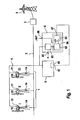
- FIG. 1 An exemplary embodiment of a wind farm with a harmonic predictor according to the invention is shown in FIG. 1 shown.
- the wind farm comprises a plurality of wind turbines 1, wherein in the illustrated embodiment, three wind turbines are provided. They have a similar structure and are identified for identification with the Roman numerals I, II or III.
- the wind turbines 1 each have a doubly-fed asynchronous generator 10 with an inverter 11 and are connected to deliver the generated electrical energy to a collecting network 2, which is designed as a medium-voltage network. It leads to a connection point 3, which usually includes a high-voltage transformer (not shown) for connection to a high-voltage network 9.
- a wind farm master 5 which exerts a higher-level regulation for the wind energy plants of the wind farm.
- the wind farm master 5 is connected via a separate signal line network 4 with the wind turbines 1.
- a harmonic predictor 6 connected to the signal line network 4 is a harmonic predictor 6. It comprises a calculation module 61, an iteration module 62 and the summation module 63. The iteration module 62 and the summation module 63 are combined to form a recursion module 64. An input 65 for the order of the harmonic n to be processed by the harmonic predictor is arranged on the calculation module 61. Usually, small even-numbered ordinal numbers are given here. Furthermore, an input 66 for a harmonic threshold is provided at the harmonic predictor 6. An output terminal 67 of the harmonic predictor 6 is fed back to a limiter 68, which is arranged on the parkmaster 5.
- signals are provided by the wind turbine 1 to the harmonic to be treated, in particular with respect to the phase-locked and phase-variable component.
- this information is available in an operating control of the wind energy plant 1 and can be queried therefrom, since it has corresponding sensors in the wind energy plant 1 itself.
- the corresponding values are detected separately by sensors 14 at the individual wind energy plants and transmitted via the signal line network 4.
- the calculation module 61 determines a complex mean value of the harmonic over at least one full period and calculates therefrom a substitute vector. This will be explained below with reference to the FIGS. 4 and 5 shown in more detail.
- FIG. 4 is in the complex plane a harmonic of one of the wind turbines, as an example, the wind turbine I, shown.
- the harmonic has a phase-locked part as well as a phase-variable part.
- the coordinate system for the complex representation of the harmonic is chosen so that the phase-locked part lies on the real axis.
- the phase-locked part is in FIG. 4 with a dashed horizontal Arrow shown.
- the phase-variable part Added to the phase-locked part is the phase-variable part, which is represented as a circularly circulating vector with a thin solid arrow. This arrow reverses (rotates) with the frequency resulting from the order of the harmonic.
- the total value of the harmonic is represented at any given time by the tip of the thin arrow, the root of which lies at the top of the dashed arrow for the phase-locked part. This results in the in FIG. 5 displayed characteristic values.
- the real part of the harmonic is in FIG. 5 represented by the dashed line, and the imaginary part of the harmonic is shown by the solid line.
- the amount of the complex number defined by the respective real part and imaginary part is represented by the dot-dash line. It is noticeable that unlike the lines for the real or imaginary part, this line does not have a sinusoidal course, but rather has a flattening in the area around the angle of 180 °. This results from the fact that when looking at the arrowhead the solid line in FIG.
- the horizontal lines represent the mean values for the real part (dashed line) and the mean value for the total value of the harmonic (phase-locked and phase-variable part) in dot-dashed representation.
- the mean value for the complex vector of the harmonic is also complex and is in FIG. 4 represented by a cross. This serves according to the invention as a substitute value for the harmonic whose amount corresponds to the average amplitude of the harmonic.
- the calculation module 61 supplies at its output this complex mean value as a replacement vector.
- the iteration module 62 ensures that the calculation for the other wind turbines, which is illustrated above using the example of the wind power plant I, is repeated correspondingly in Examples II and III.
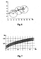
- the summing module 63 adds these values. This is in FIG. 6 visualized. It contains three circular representations, which are designated with the Roman numbers I, II and III for the three wind turbines. The representation of the first circle corresponds to that in FIG. 4 for the wind energy plant I.
- the replacement vector functioning as replacement value is represented by the dot-dashed arrow near the Roman number I. Starting from this substitute value, ie graphically starting from the peak of the substitute vector, the calculation for the second wind turbine II is performed.
- this process is repeated for the third wind turbine III, resulting in the third substitute vector, which is indicated by the dot-dash line Arrow near the number III in FIG. 6 is shown.
- the summation module 63 finally forms from these three substitute vectors an overall vector T, which is represented by a thick solid line. It represents the mean value of the total harmonic contribution generated by the wind turbines I - III taking into account the respective phase-locked and phase-variable components and their relative phase position.
- the harmonic predictor according to the invention can be used to drive converters 11 for generators 10 of wind turbines 1 such that their harmonics are set with respect to the phase-locked and phase-variable part such that the total vector T determined by the harmonic predictor 6 does not exceed the harmonic limit LIMIT.
- the inverter 11 can also be provided that in critical cases, the number N of wind turbines is reduced, so as to achieve a reduction of the harmonic.
- the principle of the harmonic predictor per se can be applied to any type of wind turbine 1, it has been proven especially in wind turbines with double-fed asynchronous generator 10. Particularly in these cases, the problem of the mixed case, ie a harmonic with a phase-locked and phase-variable part, occurs in particular.
- the harmonic predictor 6 it is not absolutely necessary that the harmonic predictor 6 is implemented on a real wind farm. It is also possible to use the harmonic predictor 6 on a simulation interface 7 (see FIG. Fig. 2 ), which cooperates with a simulation computer 70.
- the simulation interface 7 has a connection 74 for simulating the signal network with the devices connected thereto and a connection 77 for applying an output signal 67 'of the harmonic predictor 6.
- FIG. 3 The improvements possible with the harmonic predictor according to the invention are in FIG. 3 shown.
- the desired ideal state is a reduction of the harmonic with a reduction factor RF according to a relationship 1 / ⁇ (N), which conventionally can only be achieved in higher order harmonics; this one is in FIG. 3 represented by a dotted line.
- a reduction can be achieved, as represented by the solid line is shown. It can be seen that, although not quite as strong a reduction is achieved as in the higher order harmonics, but still achieved a considerable improvement over the previous case, in which no reduction, but a constant value of 1 according to the dashed line was assumed.
- the harmonic load can be estimated more accurately, which ultimately allows the connection of more wind turbines in a wind farm at a given connection with predetermined harmonic threshold. It is particularly pleasing that with the harmonic predictor even with relatively small wind farms with ten or twenty turbines a considerable reduction of the harmonic load is possible.
Landscapes
- Engineering & Computer Science (AREA)
- Power Engineering (AREA)
- Life Sciences & Earth Sciences (AREA)
- Sustainable Development (AREA)
- Sustainable Energy (AREA)
- Chemical & Material Sciences (AREA)
- Combustion & Propulsion (AREA)
- Mechanical Engineering (AREA)
- General Engineering & Computer Science (AREA)
- Wind Motors (AREA)
- Control Of Eletrric Generators (AREA)
Applications Claiming Priority (2)
| Application Number | Priority Date | Filing Date | Title |
|---|---|---|---|
| US201261590100P | 2012-01-24 | 2012-01-24 | |
| PCT/EP2013/051311 WO2013110691A2 (de) | 2012-01-24 | 2013-01-24 | Windpark-oberschwingungsprädiktor und verfahren dazu |
Publications (2)
| Publication Number | Publication Date |
|---|---|
| EP2807743A2 EP2807743A2 (de) | 2014-12-03 |
| EP2807743B1 true EP2807743B1 (de) | 2016-01-13 |
Family
ID=47630323
Family Applications (1)
| Application Number | Title | Priority Date | Filing Date |
|---|---|---|---|
| EP13702002.0A Not-in-force EP2807743B1 (de) | 2012-01-24 | 2013-01-24 | Windpark-oberschwingungsprädiktor und verfahren dazu |
Country Status (6)
| Country | Link |
|---|---|
| US (1) | US9397599B2 (da) |
| EP (1) | EP2807743B1 (da) |
| CA (1) | CA2861955C (da) |
| DK (1) | DK2807743T3 (da) |
| ES (1) | ES2566153T3 (da) |
| WO (1) | WO2013110691A2 (da) |
Families Citing this family (29)
| Publication number | Priority date | Publication date | Assignee | Title |
|---|---|---|---|---|
| DE102013218645B3 (de) * | 2013-09-17 | 2015-01-22 | Senvion Se | Verfahren und Anordnung zum Ermitteln der elektrischen Eigenschaften einer Windenergieanlage |
| CN103490426B (zh) * | 2013-09-25 | 2018-02-16 | 国家电网公司 | 大规模风电接入的弱送端电力系统电压稳定综合控制方法 |
| DE102014209332A1 (de) * | 2014-05-16 | 2015-11-19 | Senvion Gmbh | Windenergieanlage mit verbessertem Überspannungsschutz |
| CN105449664B (zh) * | 2014-09-01 | 2018-05-08 | 北京华建网源电力设计研究院有限公司 | 一种风电消纳能力计算方法及系统 |
| CN105207255B (zh) * | 2015-09-15 | 2018-03-20 | 国家电网公司 | 一种适用于风电出力的电力系统调峰计算方法 |
| CN105244870B (zh) * | 2015-10-16 | 2018-06-26 | 西安交通大学 | 一种快速计算电网风电场弃风率及机组发电量的方法 |
| CN105337290B (zh) * | 2015-11-23 | 2019-08-16 | 中国电力科学研究院 | 一种适用于电力系统低频振荡辅助决策的无功调整方法 |
| CN105633949B (zh) * | 2015-12-14 | 2018-07-24 | 云南电网有限责任公司电力科学研究院 | 一种经济运行实时发电调度和控制方法 |
| CN105471000B (zh) * | 2015-12-29 | 2018-06-29 | 安徽立卓智能电网科技有限公司 | 一种具有两段低压母线的风电场无功分配方法 |
| CN105610200A (zh) * | 2016-01-25 | 2016-05-25 | 安徽立卓智能电网科技有限公司 | 一种基于同步协调控制的火电厂全功率控制方法 |
| CN105515061B (zh) * | 2016-01-25 | 2018-05-25 | 云南电网有限责任公司电力科学研究院 | 一种风电机组有功功率控制方法和系统 |
| CN105552922B (zh) * | 2016-01-25 | 2018-04-17 | 安徽立卓智能电网科技有限公司 | 一种基于北斗卫星通信的非统调电厂自动电压控制方法及系统 |
| CN105790266B (zh) * | 2016-04-27 | 2018-07-13 | 华东交通大学 | 一种微电网并行多目标鲁棒优化调度集成控制方法 |
| CN105743215B (zh) * | 2016-05-05 | 2018-04-03 | 江苏省镇江船厂(集团)有限公司 | 船舶环网配电系统闭锁保护电路 |
| CN105743132B (zh) * | 2016-05-05 | 2018-03-27 | 江苏省镇江船厂(集团)有限公司 | 船舶主电站两级配电双环网系统 |
| CN106026199B (zh) * | 2016-05-11 | 2018-05-25 | 安徽立卓智能电网科技有限公司 | 一种风电场区域分层无功控制方法 |
| CN105977984B (zh) * | 2016-06-28 | 2018-12-21 | 江苏省镇江船厂(集团)有限公司 | 变频主电源船舶电站 |
| CN106487015A (zh) * | 2016-06-29 | 2017-03-08 | 南京软核科技有限公司 | 一种配电网多级协调控制系统及其节能优化方法 |
| CN106253445A (zh) * | 2016-08-30 | 2016-12-21 | 安徽鸿路钢结构(集团)股份有限公司 | 用太阳能供电与市电综合供电系统的垂直升降立体车库 |
| CN106253293B (zh) * | 2016-08-31 | 2019-01-22 | 国网青海省电力公司 | 一种新能源出力对电力系统网络潮流影响的分析方法 |
| CN106253282A (zh) * | 2016-08-31 | 2016-12-21 | 四川创能电力工程有限公司 | 一种谐波处理方法以及一种电网系统 |
| CN106451766B (zh) * | 2016-09-09 | 2019-03-05 | 国家电网公司 | 一种智能供电管理方法和智能电表 |
| CN106505619B (zh) * | 2016-11-25 | 2020-01-07 | 国家电网公司 | 一种考虑水电和风电场联合进行电网黑启动的方法 |
| CN106712626B (zh) * | 2017-01-22 | 2018-11-27 | 西安理工大学 | 一种异步电机模型预测控制方法 |
| WO2019120398A1 (en) | 2017-12-19 | 2019-06-27 | Vestas Wind Systems A/S | Method for damping harmonics |
| EP3582378A1 (en) * | 2018-06-12 | 2019-12-18 | Siemens Gamesa Renewable Energy A/S | Selecting switching times of wind turbine converters |
| WO2020057704A1 (en) | 2018-09-19 | 2020-03-26 | Vestas Wind Systems A/S | Control of a wind turbine power generation system for optimising dc link voltage |
| US11261846B2 (en) * | 2019-11-01 | 2022-03-01 | General Electric Company | System and method for designing and operating a wind turbine power system based on statistical analysis of operational and/or grid data thereof |
| CA3211858A1 (en) | 2021-02-26 | 2022-09-01 | General Electric Renovables Espana S.L. | System and method for reducing farm-level power oscillations in the grid induced by a wind farm |
Family Cites Families (8)
| Publication number | Priority date | Publication date | Assignee | Title |
|---|---|---|---|---|
| DK2115298T3 (da) * | 2007-01-17 | 2021-02-01 | New World Generation Inc | Vindturbine med flere generatorer og fremgangsmåde til betjening |
| DE102007005852A1 (de) * | 2007-02-01 | 2008-08-14 | Repower Systems Ag | Windpark umfassend Windenergieanlagen mit zueinander verschobenem Schwenkwinkel |
| GB2449427B (en) * | 2007-05-19 | 2012-09-26 | Converteam Technology Ltd | Control methods for the synchronisation and phase shift of the pulse width modulation (PWM) strategy of power converters |
| US20090150126A1 (en) | 2007-12-10 | 2009-06-11 | Yahoo! Inc. | System and method for sparse gaussian process regression using predictive measures |
| ES2333393B1 (es) * | 2008-06-06 | 2011-01-07 | Accioona Windpower, S.A | Sistema y metodo de control de un aerogenerador. |
| EP2313652B1 (en) * | 2008-06-30 | 2016-07-27 | Vestas Wind Systems A/S | A method of controlling a wind power plant |
| US7999418B2 (en) * | 2008-12-22 | 2011-08-16 | General Electric Company | Electrical system and control method |
| BR112012016577A2 (pt) * | 2010-01-04 | 2018-09-18 | Cinnober Financial Tech Ab | "sistema de negociação automatizado, método para compatibilização de ordens em um sistema de negociação automatizado,e, programa de computador" |
-
2013
- 2013-01-24 ES ES13702002.0T patent/ES2566153T3/es active Active
- 2013-01-24 US US13/749,251 patent/US9397599B2/en not_active Expired - Fee Related
- 2013-01-24 CA CA2861955A patent/CA2861955C/en active Active
- 2013-01-24 DK DK13702002.0T patent/DK2807743T3/da active
- 2013-01-24 EP EP13702002.0A patent/EP2807743B1/de not_active Not-in-force
- 2013-01-24 WO PCT/EP2013/051311 patent/WO2013110691A2/de not_active Ceased
Also Published As
| Publication number | Publication date |
|---|---|
| WO2013110691A2 (de) | 2013-08-01 |
| CA2861955C (en) | 2017-10-24 |
| ES2566153T3 (es) | 2016-04-11 |
| US20130207393A1 (en) | 2013-08-15 |
| CA2861955A1 (en) | 2013-08-01 |
| WO2013110691A3 (de) | 2013-11-07 |
| US9397599B2 (en) | 2016-07-19 |
| DK2807743T3 (da) | 2016-04-04 |
| EP2807743A2 (de) | 2014-12-03 |
Similar Documents
| Publication | Publication Date | Title |
|---|---|---|
| EP2807743B1 (de) | Windpark-oberschwingungsprädiktor und verfahren dazu | |
| EP2872777B1 (de) | Verfahren zum steuern eines elektrischen erzeugers | |
| EP3326255B1 (de) | Verfahren und vorrichtung zum erfassen einer elektrischen spannung in einem versorgungsnetz | |
| EP3275075B1 (de) | Verfahren zum steuern eines synchrongenerators einer getriebelosen windenergieanlage | |
| DE102011053237A1 (de) | Verfahren zur Stabilisierung eines elektrischen Versorgungsnetzes | |
| DE60221668T2 (de) | Verfahren zur überwachung eines hochspannungsnetzes | |
| EP3926162B1 (de) | Verfahren zum betrieb einer windenergieanlage, steuerungsvorrichtung zum betrieb einer windenergieanlage und windpark | |
| DE102012015323A1 (de) | Maximum Power Point Tracker | |
| EP3033816B1 (de) | Verfahren zum einspeisen elektrischer leistung in ein versorgungsnetz | |
| EP3818384A1 (de) | Windenergiesystem und verfahren zum erkennen niederfrequenter schwingungen in einem elektrischen versorgungsnetz | |
| DE102014016664A1 (de) | Verfahren zum Betreiben einer Windenenergieanlage mit komplexer Umrichtersteuerung und Vorrichtung hierfür | |
| EP3308442B1 (de) | Verfahren zur rechnergestützten parametrierung eines umrichters in einem stromnetz | |
| DE1474101A1 (de) | Vielkanal-Korrelationsrechner | |
| EP2238665B1 (de) | Verfahren zum betreiben einer windenergieanlage | |
| DE102017008936A1 (de) | Windenergieanlage mit oberschwingungsarmen Umrichtersystem sowie Verfahren zum Betrieb | |
| EP2351204B1 (de) | Vorrichtung zur regelung einer doppelt gespeisten asynchronmaschine | |
| EP4236004A2 (de) | Bereitstellen von regelleistung beim betrieb einer regenerativen stromerzeugungseinheit, insbesondere windenergieanlage | |
| EP2945245B1 (de) | Verfahren und Vorrichtung zum Reduzieren von Spannungsschwankungen in einem Versorgungsnetz | |
| WO2014033331A2 (de) | Verfahren und vorrichtung zum betreiben einer stromerzeugungseinrichtung mit wechselrichter | |
| EP1736664B1 (de) | Verfahren und Anordnung zum Vermessen einer Windenergieanlage | |
| EP4170848A1 (de) | Verfahren zum dämpfen niederfrequenter schwingungen in einem elektrischen versorgungsnetz | |
| EP1708349A1 (de) | Stromregelung eines Netzparallelen Spannungsumrichters | |
| EP4033646A1 (de) | Verfahren und vorrichtung zur verringerung von stromoberschwingungen | |
| EP3047291B1 (de) | Verfahren und anordnung zum ermitteln der elektrischen eigenschaften einer windenergieanlage | |
| DE102011086988B3 (de) | Verfahren zum Betrieb einer Windturbine |
Legal Events
| Date | Code | Title | Description |
|---|---|---|---|
| PUAI | Public reference made under article 153(3) epc to a published international application that has entered the european phase |
Free format text: ORIGINAL CODE: 0009012 |
|
| 17P | Request for examination filed |
Effective date: 20140707 |
|
| AK | Designated contracting states |
Kind code of ref document: A2 Designated state(s): AL AT BE BG CH CY CZ DE DK EE ES FI FR GB GR HR HU IE IS IT LI LT LU LV MC MK MT NL NO PL PT RO RS SE SI SK SM TR |
|
| DAX | Request for extension of the european patent (deleted) | ||
| GRAP | Despatch of communication of intention to grant a patent |
Free format text: ORIGINAL CODE: EPIDOSNIGR1 |
|
| INTG | Intention to grant announced |
Effective date: 20150715 |
|
| RAP1 | Party data changed (applicant data changed or rights of an application transferred) |
Owner name: SENVION GMBH |
|
| GRAS | Grant fee paid |
Free format text: ORIGINAL CODE: EPIDOSNIGR3 |
|
| GRAA | (expected) grant |
Free format text: ORIGINAL CODE: 0009210 |
|
| AK | Designated contracting states |
Kind code of ref document: B1 Designated state(s): AL AT BE BG CH CY CZ DE DK EE ES FI FR GB GR HR HU IE IS IT LI LT LU LV MC MK MT NL NO PL PT RO RS SE SI SK SM TR |
|
| REG | Reference to a national code |
Ref country code: GB Ref legal event code: FG4D Free format text: NOT ENGLISH |
|
| REG | Reference to a national code |
Ref country code: CH Ref legal event code: EP |
|
| REG | Reference to a national code |
Ref country code: IE Ref legal event code: FG4D Free format text: LANGUAGE OF EP DOCUMENT: GERMAN |
|
| REG | Reference to a national code |
Ref country code: AT Ref legal event code: REF Ref document number: 771091 Country of ref document: AT Kind code of ref document: T Effective date: 20160215 |
|
| REG | Reference to a national code |
Ref country code: DE Ref legal event code: R096 Ref document number: 502013001793 Country of ref document: DE |
|
| REG | Reference to a national code |
Ref country code: FR Ref legal event code: PLFP Year of fee payment: 4 |
|
| REG | Reference to a national code |
Ref country code: DK Ref legal event code: T3 Effective date: 20160331 |
|
| REG | Reference to a national code |
Ref country code: ES Ref legal event code: FG2A Ref document number: 2566153 Country of ref document: ES Kind code of ref document: T3 Effective date: 20160411 |
|
| REG | Reference to a national code |
Ref country code: LT Ref legal event code: MG4D |
|
| REG | Reference to a national code |
Ref country code: NL Ref legal event code: MP Effective date: 20160113 |
|
| PG25 | Lapsed in a contracting state [announced via postgrant information from national office to epo] |
Ref country code: BE Free format text: LAPSE BECAUSE OF NON-PAYMENT OF DUE FEES Effective date: 20160131 |
|
| PG25 | Lapsed in a contracting state [announced via postgrant information from national office to epo] |
Ref country code: NL Free format text: LAPSE BECAUSE OF FAILURE TO SUBMIT A TRANSLATION OF THE DESCRIPTION OR TO PAY THE FEE WITHIN THE PRESCRIBED TIME-LIMIT Effective date: 20160113 |
|
| PG25 | Lapsed in a contracting state [announced via postgrant information from national office to epo] |
Ref country code: HR Free format text: LAPSE BECAUSE OF FAILURE TO SUBMIT A TRANSLATION OF THE DESCRIPTION OR TO PAY THE FEE WITHIN THE PRESCRIBED TIME-LIMIT Effective date: 20160113 Ref country code: FI Free format text: LAPSE BECAUSE OF FAILURE TO SUBMIT A TRANSLATION OF THE DESCRIPTION OR TO PAY THE FEE WITHIN THE PRESCRIBED TIME-LIMIT Effective date: 20160113 Ref country code: IT Free format text: LAPSE BECAUSE OF FAILURE TO SUBMIT A TRANSLATION OF THE DESCRIPTION OR TO PAY THE FEE WITHIN THE PRESCRIBED TIME-LIMIT Effective date: 20160113 Ref country code: NO Free format text: LAPSE BECAUSE OF FAILURE TO SUBMIT A TRANSLATION OF THE DESCRIPTION OR TO PAY THE FEE WITHIN THE PRESCRIBED TIME-LIMIT Effective date: 20160413 Ref country code: GR Free format text: LAPSE BECAUSE OF FAILURE TO SUBMIT A TRANSLATION OF THE DESCRIPTION OR TO PAY THE FEE WITHIN THE PRESCRIBED TIME-LIMIT Effective date: 20160414 |
|
| PG25 | Lapsed in a contracting state [announced via postgrant information from national office to epo] |
Ref country code: LT Free format text: LAPSE BECAUSE OF FAILURE TO SUBMIT A TRANSLATION OF THE DESCRIPTION OR TO PAY THE FEE WITHIN THE PRESCRIBED TIME-LIMIT Effective date: 20160113 Ref country code: LV Free format text: LAPSE BECAUSE OF FAILURE TO SUBMIT A TRANSLATION OF THE DESCRIPTION OR TO PAY THE FEE WITHIN THE PRESCRIBED TIME-LIMIT Effective date: 20160113 Ref country code: RS Free format text: LAPSE BECAUSE OF FAILURE TO SUBMIT A TRANSLATION OF THE DESCRIPTION OR TO PAY THE FEE WITHIN THE PRESCRIBED TIME-LIMIT Effective date: 20160113 Ref country code: PT Free format text: LAPSE BECAUSE OF FAILURE TO SUBMIT A TRANSLATION OF THE DESCRIPTION OR TO PAY THE FEE WITHIN THE PRESCRIBED TIME-LIMIT Effective date: 20160513 Ref country code: PL Free format text: LAPSE BECAUSE OF FAILURE TO SUBMIT A TRANSLATION OF THE DESCRIPTION OR TO PAY THE FEE WITHIN THE PRESCRIBED TIME-LIMIT Effective date: 20160113 Ref country code: IS Free format text: LAPSE BECAUSE OF FAILURE TO SUBMIT A TRANSLATION OF THE DESCRIPTION OR TO PAY THE FEE WITHIN THE PRESCRIBED TIME-LIMIT Effective date: 20160513 Ref country code: SE Free format text: LAPSE BECAUSE OF FAILURE TO SUBMIT A TRANSLATION OF THE DESCRIPTION OR TO PAY THE FEE WITHIN THE PRESCRIBED TIME-LIMIT Effective date: 20160113 |
|
| REG | Reference to a national code |
Ref country code: CH Ref legal event code: PL |
|
| REG | Reference to a national code |
Ref country code: DE Ref legal event code: R097 Ref document number: 502013001793 Country of ref document: DE |
|
| PG25 | Lapsed in a contracting state [announced via postgrant information from national office to epo] |
Ref country code: EE Free format text: LAPSE BECAUSE OF FAILURE TO SUBMIT A TRANSLATION OF THE DESCRIPTION OR TO PAY THE FEE WITHIN THE PRESCRIBED TIME-LIMIT Effective date: 20160113 Ref country code: MC Free format text: LAPSE BECAUSE OF FAILURE TO SUBMIT A TRANSLATION OF THE DESCRIPTION OR TO PAY THE FEE WITHIN THE PRESCRIBED TIME-LIMIT Effective date: 20160113 Ref country code: CH Free format text: LAPSE BECAUSE OF NON-PAYMENT OF DUE FEES Effective date: 20160131 Ref country code: LI Free format text: LAPSE BECAUSE OF NON-PAYMENT OF DUE FEES Effective date: 20160131 |
|
| REG | Reference to a national code |
Ref country code: IE Ref legal event code: MM4A |
|
| PLBE | No opposition filed within time limit |
Free format text: ORIGINAL CODE: 0009261 |
|
| STAA | Information on the status of an ep patent application or granted ep patent |
Free format text: STATUS: NO OPPOSITION FILED WITHIN TIME LIMIT |
|
| PG25 | Lapsed in a contracting state [announced via postgrant information from national office to epo] |
Ref country code: CZ Free format text: LAPSE BECAUSE OF FAILURE TO SUBMIT A TRANSLATION OF THE DESCRIPTION OR TO PAY THE FEE WITHIN THE PRESCRIBED TIME-LIMIT Effective date: 20160113 Ref country code: SM Free format text: LAPSE BECAUSE OF FAILURE TO SUBMIT A TRANSLATION OF THE DESCRIPTION OR TO PAY THE FEE WITHIN THE PRESCRIBED TIME-LIMIT Effective date: 20160113 Ref country code: SK Free format text: LAPSE BECAUSE OF FAILURE TO SUBMIT A TRANSLATION OF THE DESCRIPTION OR TO PAY THE FEE WITHIN THE PRESCRIBED TIME-LIMIT Effective date: 20160113 Ref country code: RO Free format text: LAPSE BECAUSE OF FAILURE TO SUBMIT A TRANSLATION OF THE DESCRIPTION OR TO PAY THE FEE WITHIN THE PRESCRIBED TIME-LIMIT Effective date: 20160113 |
|
| 26N | No opposition filed |
Effective date: 20161014 |
|
| REG | Reference to a national code |
Ref country code: FR Ref legal event code: PLFP Year of fee payment: 5 |
|
| PG25 | Lapsed in a contracting state [announced via postgrant information from national office to epo] |
Ref country code: IE Free format text: LAPSE BECAUSE OF NON-PAYMENT OF DUE FEES Effective date: 20160124 |
|
| PG25 | Lapsed in a contracting state [announced via postgrant information from national office to epo] |
Ref country code: BG Free format text: LAPSE BECAUSE OF FAILURE TO SUBMIT A TRANSLATION OF THE DESCRIPTION OR TO PAY THE FEE WITHIN THE PRESCRIBED TIME-LIMIT Effective date: 20160413 Ref country code: SI Free format text: LAPSE BECAUSE OF FAILURE TO SUBMIT A TRANSLATION OF THE DESCRIPTION OR TO PAY THE FEE WITHIN THE PRESCRIBED TIME-LIMIT Effective date: 20160113 |
|
| PG25 | Lapsed in a contracting state [announced via postgrant information from national office to epo] |
Ref country code: MT Free format text: LAPSE BECAUSE OF FAILURE TO SUBMIT A TRANSLATION OF THE DESCRIPTION OR TO PAY THE FEE WITHIN THE PRESCRIBED TIME-LIMIT Effective date: 20160113 |
|
| REG | Reference to a national code |
Ref country code: FR Ref legal event code: PLFP Year of fee payment: 6 |
|
| PG25 | Lapsed in a contracting state [announced via postgrant information from national office to epo] |
Ref country code: HU Free format text: LAPSE BECAUSE OF FAILURE TO SUBMIT A TRANSLATION OF THE DESCRIPTION OR TO PAY THE FEE WITHIN THE PRESCRIBED TIME-LIMIT; INVALID AB INITIO Effective date: 20130124 |
|
| PG25 | Lapsed in a contracting state [announced via postgrant information from national office to epo] |
Ref country code: LU Free format text: LAPSE BECAUSE OF NON-PAYMENT OF DUE FEES Effective date: 20160124 Ref country code: CY Free format text: LAPSE BECAUSE OF FAILURE TO SUBMIT A TRANSLATION OF THE DESCRIPTION OR TO PAY THE FEE WITHIN THE PRESCRIBED TIME-LIMIT Effective date: 20160113 Ref country code: MK Free format text: LAPSE BECAUSE OF FAILURE TO SUBMIT A TRANSLATION OF THE DESCRIPTION OR TO PAY THE FEE WITHIN THE PRESCRIBED TIME-LIMIT Effective date: 20160113 |
|
| PG25 | Lapsed in a contracting state [announced via postgrant information from national office to epo] |
Ref country code: AL Free format text: LAPSE BECAUSE OF FAILURE TO SUBMIT A TRANSLATION OF THE DESCRIPTION OR TO PAY THE FEE WITHIN THE PRESCRIBED TIME-LIMIT Effective date: 20160113 Ref country code: TR Free format text: LAPSE BECAUSE OF FAILURE TO SUBMIT A TRANSLATION OF THE DESCRIPTION OR TO PAY THE FEE WITHIN THE PRESCRIBED TIME-LIMIT Effective date: 20160113 |
|
| REG | Reference to a national code |
Ref country code: AT Ref legal event code: MM01 Ref document number: 771091 Country of ref document: AT Kind code of ref document: T Effective date: 20180124 |
|
| PG25 | Lapsed in a contracting state [announced via postgrant information from national office to epo] |
Ref country code: AT Free format text: LAPSE BECAUSE OF NON-PAYMENT OF DUE FEES Effective date: 20180124 |
|
| REG | Reference to a national code |
Ref country code: DE Ref legal event code: R081 Ref document number: 502013001793 Country of ref document: DE Owner name: SIEMENS GAMESA RENEWABLE ENERGY SERVICE GMBH, DE Free format text: FORMER OWNER: SENVION GMBH, 22297 HAMBURG, DE |
|
| PGFP | Annual fee paid to national office [announced via postgrant information from national office to epo] |
Ref country code: FR Payment date: 20230123 Year of fee payment: 11 Ref country code: ES Payment date: 20230216 Year of fee payment: 11 Ref country code: DK Payment date: 20230123 Year of fee payment: 11 |
|
| PGFP | Annual fee paid to national office [announced via postgrant information from national office to epo] |
Ref country code: GB Payment date: 20230124 Year of fee payment: 11 Ref country code: DE Payment date: 20230119 Year of fee payment: 11 |
|
| REG | Reference to a national code |
Ref country code: GB Ref legal event code: 732E Free format text: REGISTERED BETWEEN 20230727 AND 20230802 |
|
| REG | Reference to a national code |
Ref country code: DE Ref legal event code: R119 Ref document number: 502013001793 Country of ref document: DE |
|
| REG | Reference to a national code |
Ref country code: DK Ref legal event code: EBP Effective date: 20240131 |
|
| REG | Reference to a national code |
Ref country code: ES Ref legal event code: PC2A Owner name: SIEMENS GAMESA RENEWABLE ENERGY SERVICE GMBH Effective date: 20240819 |
|
| GBPC | Gb: european patent ceased through non-payment of renewal fee |
Effective date: 20240124 |
|
| PG25 | Lapsed in a contracting state [announced via postgrant information from national office to epo] |
Ref country code: DE Free format text: LAPSE BECAUSE OF NON-PAYMENT OF DUE FEES Effective date: 20240801 |
|
| PG25 | Lapsed in a contracting state [announced via postgrant information from national office to epo] |
Ref country code: GB Free format text: LAPSE BECAUSE OF NON-PAYMENT OF DUE FEES Effective date: 20240124 |
|
| PG25 | Lapsed in a contracting state [announced via postgrant information from national office to epo] |
Ref country code: FR Free format text: LAPSE BECAUSE OF NON-PAYMENT OF DUE FEES Effective date: 20240131 |
|
| PG25 | Lapsed in a contracting state [announced via postgrant information from national office to epo] |
Ref country code: GB Free format text: LAPSE BECAUSE OF NON-PAYMENT OF DUE FEES Effective date: 20240124 Ref country code: FR Free format text: LAPSE BECAUSE OF NON-PAYMENT OF DUE FEES Effective date: 20240131 Ref country code: DE Free format text: LAPSE BECAUSE OF NON-PAYMENT OF DUE FEES Effective date: 20240801 |
|
| PG25 | Lapsed in a contracting state [announced via postgrant information from national office to epo] |
Ref country code: DK Free format text: LAPSE BECAUSE OF NON-PAYMENT OF DUE FEES Effective date: 20240131 |
|
| PG25 | Lapsed in a contracting state [announced via postgrant information from national office to epo] |
Ref country code: DK Free format text: LAPSE BECAUSE OF NON-PAYMENT OF DUE FEES Effective date: 20240131 |
|
| REG | Reference to a national code |
Ref country code: ES Ref legal event code: FD2A Effective date: 20250228 |
|
| PG25 | Lapsed in a contracting state [announced via postgrant information from national office to epo] |
Ref country code: ES Free format text: LAPSE BECAUSE OF NON-PAYMENT OF DUE FEES Effective date: 20240125 |