EP2807327B1 - Device for anchoring in a casing in a borehole in the ground - Google Patents
Device for anchoring in a casing in a borehole in the ground Download PDFInfo
- Publication number
- EP2807327B1 EP2807327B1 EP12821206.5A EP12821206A EP2807327B1 EP 2807327 B1 EP2807327 B1 EP 2807327B1 EP 12821206 A EP12821206 A EP 12821206A EP 2807327 B1 EP2807327 B1 EP 2807327B1
- Authority
- EP
- European Patent Office
- Prior art keywords
- casing
- latch
- annular recess
- clamping
- torque transfer
- Prior art date
- Legal status (The legal status is an assumption and is not a legal conclusion. Google has not performed a legal analysis and makes no representation as to the accuracy of the status listed.)
- Not-in-force
Links
- 238000004873 anchoring Methods 0.000 title claims description 57
- 238000005553 drilling Methods 0.000 claims description 34
- 238000010168 coupling process Methods 0.000 claims description 17
- 238000005859 coupling reaction Methods 0.000 claims description 17
- 230000008878 coupling Effects 0.000 claims description 16
- 239000000463 material Substances 0.000 claims description 13
- 230000005291 magnetic effect Effects 0.000 claims description 4
- 239000002131 composite material Substances 0.000 claims description 3
- 238000003780 insertion Methods 0.000 claims description 3
- 230000037431 insertion Effects 0.000 claims description 3
- XAGFODPZIPBFFR-UHFFFAOYSA-N aluminium Chemical compound [Al] XAGFODPZIPBFFR-UHFFFAOYSA-N 0.000 claims description 2
- 229910052782 aluminium Inorganic materials 0.000 claims description 2
- 239000004411 aluminium Substances 0.000 claims description 2
- 230000005294 ferromagnetic effect Effects 0.000 claims description 2
- 230000035699 permeability Effects 0.000 claims description 2
- 239000000126 substance Substances 0.000 claims description 2
- 238000007789 sealing Methods 0.000 description 4
- 230000015572 biosynthetic process Effects 0.000 description 3
- 238000006073 displacement reaction Methods 0.000 description 3
- 238000005755 formation reaction Methods 0.000 description 3
- 238000006243 chemical reaction Methods 0.000 description 2
- 230000001419 dependent effect Effects 0.000 description 2
- 238000005259 measurement Methods 0.000 description 2
- 229910000831 Steel Inorganic materials 0.000 description 1
- 239000004568 cement Substances 0.000 description 1
- 230000005465 channeling Effects 0.000 description 1
- 230000000694 effects Effects 0.000 description 1
- 239000000835 fiber Substances 0.000 description 1
- 239000012530 fluid Substances 0.000 description 1
- 239000011159 matrix material Substances 0.000 description 1
- 210000002445 nipple Anatomy 0.000 description 1
- 229920000642 polymer Polymers 0.000 description 1
- 230000002028 premature Effects 0.000 description 1
- 230000000630 rising effect Effects 0.000 description 1
- 238000010008 shearing Methods 0.000 description 1
- 239000010959 steel Substances 0.000 description 1
Images



Classifications
-
- E—FIXED CONSTRUCTIONS
- E21—EARTH OR ROCK DRILLING; MINING
- E21B—EARTH OR ROCK DRILLING; OBTAINING OIL, GAS, WATER, SOLUBLE OR MELTABLE MATERIALS OR A SLURRY OF MINERALS FROM WELLS
- E21B23/00—Apparatus for displacing, setting, locking, releasing or removing tools, packers or the like in boreholes or wells
-
- E—FIXED CONSTRUCTIONS
- E21—EARTH OR ROCK DRILLING; MINING
- E21B—EARTH OR ROCK DRILLING; OBTAINING OIL, GAS, WATER, SOLUBLE OR MELTABLE MATERIALS OR A SLURRY OF MINERALS FROM WELLS
- E21B23/00—Apparatus for displacing, setting, locking, releasing or removing tools, packers or the like in boreholes or wells
- E21B23/01—Apparatus for displacing, setting, locking, releasing or removing tools, packers or the like in boreholes or wells for anchoring the tools or the like
-
- E—FIXED CONSTRUCTIONS
- E21—EARTH OR ROCK DRILLING; MINING
- E21B—EARTH OR ROCK DRILLING; OBTAINING OIL, GAS, WATER, SOLUBLE OR MELTABLE MATERIALS OR A SLURRY OF MINERALS FROM WELLS
- E21B7/00—Special methods or apparatus for drilling
- E21B7/20—Driving or forcing casings or pipes into boreholes, e.g. sinking; Simultaneously drilling and casing boreholes
Definitions
- the invention relates to a device for anchoring in a casing in a borehole in the ground.
- a device for anchoring in a casing in a borehole in the ground.
- Such a device may for instance for downhole anchoring relative to a casing or lining of a rotary bottomhole assembly (BHA) for drilling and/or reaming a borehole in the ground, or for anchoring a drive for holding and rotating a casing.
- BHA rotary bottomhole assembly
- a casing After drilling a hole in the ground, for instance for use as an oil or gas well, for collecting geothermal energy, for storage of thermal energy or for installing a subterranean duct under a canal or other structure, usually a casing is ran into the well bore to act as a wall of the well. Casing strings are typically run into the well bore from the surface and hung from the surface or from an intermediate point between the ground surface and the bottom of the hole (in the form of a liner), each next casing string being passed down via a previously installed casing string. For sealing and holding the casing in place, cement may then be introduced in the annular space between the external surface of the casing and the internal surface of the well bore.
- a reamer shoe is conventionally mounted on a lower end of the casing string. The reamer shoe removes irregularities or obstructions from the wall of the bore and thereby facilitates the passage of the casing string and aids cementing.
- the lower end of the casing with an assembly including a motor and a drilling bit and an under reamer coupled to the motor, for drilling the hole as the casing is fed into the ground.
- the drilling bit drills a hole and is followed by the underreamer that enlarges the hole to a size beyond the bit diameter for allowing the casing and, if applicable, the reamer shoe mounted to the lower end of the casing, to follow the drilling bit and the underreamer.
- a drillable or expandable drilling bit is also possible to use a drillable or expandable drilling bit. During such operations, the casing is usually rotated driven by a top drive at the ground surface.
- the underreamer or expandable drilling bit has cutting or crushing arms, which extend to a contour of a diameter larger than the diameter of the casing, the diameter of the borehole obtained thus typically being sufficient to allow the casing, or the reaming shoe at the lower end of the casing, to follow the underreamer or expandable bit.
- the blades can be retracted to a diameter smaller than the inner diameter of the casing to allow retraction of the reaming or drilling tool through the installed casing (or at least through the portion of the casing string installed following the drilling or reaming tool).
- this object is achieved by providing a casing system according to claim 1 comprising a casing and such an anchoring device.
- the co-operating outer cam surfaces of the torque transfer section of the shaft and inner clamping body surfaces of the clamping bodies cause the clamping bodies to be clamped against the inner wall surface of the casing so that a clamped fixation of the anchoring device relative to the casing against displacement relative to the casing during rotation of the casing and/or a tool anchored to the casing is achieved.
- the clamping action and release or retraction of the clamping bodies is not significantly influenced by axial loads transfer between the casing and the anchoring device.
- FIG. 1 an example of a casing system 1 including an example of an anchoring device 2 according to the invention is shown.
- the distal end of the shown structures faces to the right.
- the distal end will also form the bottom end, but the anchoring device and casing system according to the invention are also suitable for use in boreholes that are entirely or partially horizontal or even rising upward towards the distal end.
- the anchoring device 2 is anchored near a distal (usually bottom) end portion of a casing. It is however also possible to anchor the device 2 near a proximal end of a casing, for instance for holding a casing or a liner relative to a top drive tool.
- a tool in the form of a material removing assembly 4 is connected to the anchoring device 2.
- the material removing assembly 4 is a drilling and reaming unit having a material removing head constituted by a drilling bit 5 and a retractable underreamer 6 for removing ground material by drilling a borehole and reaming the drilled borehole to a larger diameter sufficient for allowing a casing shoe 7 at a lower end of the casing string to follow the material removing assembly 4 as it progresses into the ground.
- the lower end of the casing is located closely adjacent (preferably closer than a distance equal to the inner casing diameter) to the reamer, so that drilling direction of the material removing assembly can be controlled accurately and the material removing assembly is well protected against damage that may for instance be caused by hard and sharp formation encountered in a borehole in the ground.
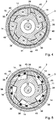
- Section II-II in Fig. 2 corresponds to section II-II in Fig. 1 .
- a mud motor (not shown) of the drilling and reaming unit 4 has a rotary part rotatable relative to a stationary motor part.
- the stationary motor part is coupled to a distal tool coupling 8 of the anchoring device 2, so that it is axially and rotationally stationary relative to the distal end portion of a casing when in operation.
- a connecting shaft may also be provided between the tool coupling 8 and the drilling and reaming unit 4 and be equipped with instruments for measuring while drilling (MWD).
- the casing may be of steel, but for allowing electromagnetic measurements while drilling, at least a section of the casing surrounding the antenna(s) of such an instrument or instruments is preferably made of electromagnetically non-shielding material, such as composite material composed of fibers embedded in a polymer matrix.
- electromagnetically non-shielding material such as composite material composed of fibers embedded in a polymer matrix.
- at least a section of the casing surrounding such an instrument or instruments is preferably made of a material having a relative magnetic permeability of approximately 1, such as most non-ferromagnetic substances, preferably of composite material as mentioned or aluminium. Such materials are also to a large extent transparent to acoustic measurement signals.
- Some lateral movement of the mud motor in operation may be provided for to allow steering of the drilling direction.
- the rotary part of the mud motor is coupled to the underreamer 6 and the drilling head 5 is coupled thereto so that rotation of the rotary part of the mud motor can drive rotation of the underreamer 6 and the drilling head 5 about a central axis 9 thereof.
- the underreamer 6 and the drilling head 5 are located distally from the mud motor.
- the anchoring device 2 is arranged for anchoring the mud motor and the drilling and reaming tool 4 in the casing string 1 so that reaction forces resulting from the torque exerted by the mud motor onto the drilling and reaming unit 4 as well as axial forces can be transferred to the casing string.
- the anchoring device 2 is releasably fixed relative to the casing string against displacement relative to the casing section 3 in longitudinal direction of the casing section 3 and in rotational sense about the centre line 9 of the casing section 3.
- the fixation is sufficiently strong to withstand forces exerted during the material removal by the drilling head 5 and the underreamer 6.
- the axial load exerted during drilling may for instance be between plus or minus 200,000 N and the torque exerted during drilling is generally between 10,000 and 150,000 Nm.
- the casing section 3 has an inner wall surface 10 clampingly engaged by the anchoring device 2.
- the anchoring device has a shaft 11 oriented in an axial direction (double arrow 12).
- the shaft 12 has a torque transfer section 13.
- the torque transfer section 13 has axially oriented outer cam surfaces 14 extending radially outwardly in a rotational sense (arrow 15).
- the shaft 11 is hollow and bounds a mud channel 16 for channeling mud to the mud motor.
- the anchoring device is provided with swap cups 47, 48 for sealing off the annular space between the anchoring device 2 and the inner wall surface 10 of the casing 3 and are arranged for resisting an operating pressure drop applied to mud to drive the mud motor.
- the swap cup 50 provides a sealing against excess pressure from the bottom of the borehole and shields the more proximal parts of the anchoring device from drill fluid, which typically contains debris produced during drilling.
- the swap cup 49 provides an additional sealing against excess pressure from the bottom of the borehole.
- a valve-operating stem 18 of a running tool 17 extends through the mud channel 16 to ports 20 in a valve section 19 of the anchoring device 2.
- the ports 20 can be opened and closed by a valve body 22 in the form of a slide with slide ports 23 that are alignable with the ports 20 for allowing mud flow to bypass the swap cups 47-50 and the mud motor.
- the running tool 17 is shown in a position after lowering of the anchoring device 2 with the tools coupled thereto to the operating position projecting from the distal end of the casing as shown in Fig. 1 .
- the slide ports 23 are aligned with the ports 20 for allowing mud to pass through as the anchoring device 2 and the tools coupled thereto are lowered through a column of mud in the casing.
- the valve section 19 may be provided with a support collar for centering the anchoring device 2 relative to the distal end portion of the casing near its distal end coupling 8.
- the running tool 17 is coupled to a proximal end-coupling member 24 of the anchoring device 2 via a breakable latch 25.
- the anchoring device 2 has latches 26 in the form of flexible fingers with radially projecting notches 27, 28 biased radially outwardly for insertion into annular recesses 29, 30 of the inner wall surface 10 of a nippel 37 of the casing. As the anchoring device 2 and the tools connected thereto are suspended from the running tool 17 and move through the casing, the latch springs 26 are pressed inwardly and engage the annular slots 29, 30 when these are reached, so that it is ensured that the anchoring device 2 is stopped at a predetermined position.
- the latch springs 26 snap outwardly so that the notches 27, 28 engage the corresponding annular recesses 29, 30 and stop the anchoring device 2 from descending further. Since the anchoring device 2 is then no longer suspended from the running tool 17 but supports the weight of the running tool 17, the running tool with the proximal coupling member 24 and the locking portion 31 descend to the descended position shown in the drawings in which the locking portion 31 is positioned between the latch springs 26, thereby locking the latch springs 26 in the radially expanded position engaging the annular recesses 29, 30.
- the running tool 17 is then uncoupled from the proximal coupling member 24 by shearing a shear pin (not shown) and lifted out of the casing together with the valve-operating stem 18.
- This causes the operating block 34 to entrain the valve slide 22 to a lifted position against abutment 35 so that the ports 20 and 23 in the valve section 19 and the valve slide 22 are out of alignment and the bypass ports 20 are closed.
- Mud pressure applied to the casing is then channeled to the mud motor.
- the operating block 34 is then pulled through the valve sleeve 22 and entrained with the operating stem 18.
- the corresponding annular recesses 29, 30 can be relatively narrow and have rounded or beveled or chamfered first and last edges. This reduces the tendency of other parts, such as swap cups, of the anchoring device 2 and the tools attached thereto to hook up with edges of the annular recesses, thereby disturbing movement of the anchoring device 2 and the tools attached thereto through the casing.
- a lower one of the protrusions 27 has beveled or chamfered upper and lower edges and an upper one of the protrusions 28 has a beveled or chamfered upper edge and a square lower edge.
- the square lower edge can then provide reliable landing against a land 36 in the inner casing wall between the annular recesses 29, 30, which land 36 is recessed relative to the inner casing surface 10 above the upper recess 30 and below the lower recess 29.
- edges of the annular recesses that meet the inner casing surface 10 above the upper recess 30 and below the lower recess 29 can be beveled or chamfered allowing a smooth passage of swap cups and other protruding parts, while hooking behind a square upper edge of the land 36 between the recesses is avoided because the land 36 is recessed relative to inner casing surface 10 above and below the annular recesses 29, 30. Reliable landing is nevertheless provided at the square upper edge of the land 36.
- mud pressure can be built up against the mud motor coupled to the distal coupling 8 to set the drill head 5 and the reamers 6 in rotation relative to the casing.
- the casing may be rotated inside the borehole in the same sense of rotation.
- the reaction torque would however set the mud motor and the anchoring device 2 coupled thereto in rotation within the casing instead of setting the drill head 5 and the reamers 6 in rotation in the desired sense of rotation 15 relative to the casing.
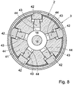
- the anchoring device 2 is equipped with a plurality of clamping bodies in the form of wedges 38 circumferentially distributed around the torque transfer section 13 with a limited movability relative to the torque transfer section 13 in rotational sense and in radial directions.
- the clamping bodies 38 each have an inner axially oriented clamping body surface 39 facing one of the cam surfaces 14 of the torque transfer section 13, an outer surface 40 defining a segment of a cylinder coaxial with the shaft 11 and converging with the inner clamping body surface 39 in the rotational sense 15.
- the reactive torque exerted by the borehole on the drill head 5 and the reamers 6 is transferred via the mud motor and the distal tool coupling 8 to the shaft 11 which is caused to rotate relative to the casing in a sense opposite to the sense of rotation 15.
- This causes the cam surfaces 14 torque transfer section 13 to engage the clamping body surfaces 39, thereby clamping the clamping bodies 38 radially outwardly with outer surfaces 40 against the inner surface 10 of the casing.
- This causes the shaft 11 to be prevented from rotating further, so that the reactive torque is transferred to the casing and the drill head 5 and the reamers 6 are set in rotation in the desired sense of rotation 15.
- the clamping bodies 38 can be released from the inner surface 10 of the casing in a reliable manner, by causing the torque transfer portion 13 of the shaft 11 to rotate in opposite sense of rotation in absence of a driving torque exerted by the mud motor.
- the rotation in the opposite sense of rotation in absence of the driving torque is caused by spring 21 that is tensioned when relative rotation of the shaft 11 and clamping bodies 38 causes the clamping bodies 38 to be urged radially outwardly. It is observed that the clamping and releasing of the anchoring device 2 is not dependent on axial displacement or positioning of the anchoring device 2 relative to the casing.
- the clamping bodies may also be provided in another form, for instance with a constant distance between the inner and outer surfaces.
- the clamping bodies in the form of wedges with the outer surfaces converging with the inner clamping body surfaces in the rotational sense, reliable release of the clamping action by rotating the torque transfer section in the rotational sense is achieved.
- the clamping bodies 38 are suspended from a clamping body carrier 41 extending around the torque transfer section 13 and coupled to the clamping bodies 38 in the rotational sense 15. By keeping the clamping bodies 38 evenly distributed in circumferential sense, accurate centering of the shaft 11 relative to the inner surface 10 of the distal end portion of the casing is achieved.
- the anchoring device is equipped with drag shoes 42 coupled to and suspended in the clamping body carrier 41 and drag shoe biasing members 43 for biasing the drag shoes 42 radially outwardly against the inner surface 10 of the casing.
- the drag shoe biasing members 43 are provided in the form of pistons in bores 44 communicating with the mud channel 16.
- clamping body biasing members in the form of springs 45 are provided for biasing the clamping bodies 38 radially inwardly.
- a running tool 17 is coupled to the proximal coupling member 24.
- a valve-operating stem 18 carrying an operating block 34 pushes the slide valve in downward direction to open the bypass ports 20 again, so that mud can flow through the anchoring device during lifting through the mud column inside the casing.
Landscapes
- Life Sciences & Earth Sciences (AREA)
- Engineering & Computer Science (AREA)
- Geology (AREA)
- Mining & Mineral Resources (AREA)
- Physics & Mathematics (AREA)
- Environmental & Geological Engineering (AREA)
- Fluid Mechanics (AREA)
- General Life Sciences & Earth Sciences (AREA)
- Geochemistry & Mineralogy (AREA)
- Earth Drilling (AREA)
- Piles And Underground Anchors (AREA)
Priority Applications (1)
| Application Number | Priority Date | Filing Date | Title |
|---|---|---|---|
| PL12821206T PL2807327T3 (pl) | 2011-12-30 | 2012-12-31 | Urządzenie do zakotwienia w rurze okładzinowej w otworze wiertniczym w gruncie |
Applications Claiming Priority (2)
| Application Number | Priority Date | Filing Date | Title |
|---|---|---|---|
| NL2008061A NL2008061C2 (en) | 2011-12-30 | 2011-12-30 | Device for anchoring in a casing in a borehole in the ground. |
| PCT/NL2012/050936 WO2013100769A1 (en) | 2011-12-30 | 2012-12-31 | Device for anchoring in a casing in a borehole in the ground |
Publications (2)
| Publication Number | Publication Date |
|---|---|
| EP2807327A1 EP2807327A1 (en) | 2014-12-03 |
| EP2807327B1 true EP2807327B1 (en) | 2017-09-13 |
Family
ID=47664396
Family Applications (1)
| Application Number | Title | Priority Date | Filing Date |
|---|---|---|---|
| EP12821206.5A Not-in-force EP2807327B1 (en) | 2011-12-30 | 2012-12-31 | Device for anchoring in a casing in a borehole in the ground |
Country Status (9)
| Country | Link |
|---|---|
| US (1) | US9121239B2 (pl) |
| EP (1) | EP2807327B1 (pl) |
| AU (1) | AU2012363432B2 (pl) |
| BR (1) | BR112014016312B1 (pl) |
| DK (1) | DK2807327T3 (pl) |
| NL (1) | NL2008061C2 (pl) |
| NO (1) | NO2807327T3 (pl) |
| PL (1) | PL2807327T3 (pl) |
| WO (1) | WO2013100769A1 (pl) |
Families Citing this family (6)
| Publication number | Priority date | Publication date | Assignee | Title |
|---|---|---|---|---|
| CA2903524C (en) * | 2011-07-14 | 2017-12-19 | Halliburton Energy Services, Inc. | Methods and systems for controlling torque transfer from rotating equipment |
| NL2014169B1 (en) | 2015-01-21 | 2017-01-05 | Huisman Well Tech | Apparatus and method for drilling a directional borehole in the ground. |
| US10662727B2 (en) | 2016-12-27 | 2020-05-26 | Cameron International Corporation | Casing hanger running tool systems and methods |
| US10669792B2 (en) | 2016-12-27 | 2020-06-02 | Cameron International Corporation | Tubing hanger running tool systems and methods |
| US10550657B2 (en) * | 2017-03-09 | 2020-02-04 | Cameron International Corporation | Hydraulic tool and seal assembly |
| CN112796692B (zh) * | 2021-04-07 | 2021-06-22 | 纬达石油装备有限公司 | 一种预应力多级地锚及其使用方法 |
Family Cites Families (18)
| Publication number | Priority date | Publication date | Assignee | Title |
|---|---|---|---|---|
| US3128826A (en) * | 1964-04-14 | brown | ||
| US1112946A (en) * | 1913-12-20 | 1914-10-06 | Walter Joseph Turnbull | Drill. |
| US2609182A (en) * | 1946-11-23 | 1952-09-02 | Arutunoff Armais | Apparatus for drilling deep wells |
| US4051910A (en) * | 1975-12-08 | 1977-10-04 | Wallace Clark | Two way earth boring fluid motor |
| US4499799A (en) * | 1983-11-25 | 1985-02-19 | Texaco Inc. | Internal gripping pipe wrench |
| US4811785A (en) * | 1987-07-31 | 1989-03-14 | Halbrite Well Services Co. Ltd. | No-turn tool |
| SE9200563L (sv) | 1992-02-25 | 1993-07-26 | Oesten Edman | Saett att utfoera borrning i jordlager samt slagsko foer saettet |
| US5771970A (en) * | 1995-11-08 | 1998-06-30 | Northwest Tech Group Inc. | Tubing tightener |
| CA2220392C (en) * | 1997-07-11 | 2001-07-31 | Variperm (Canada) Limited | Tqr anchor |
| CA2241358C (en) * | 1998-06-19 | 2007-02-06 | Ipec Ltd. | Downhole anchor |
| US6227313B1 (en) * | 1999-07-23 | 2001-05-08 | Baker Hughes Incorporated | Anti-torque tool |
| CA2444648A1 (en) * | 2002-12-06 | 2004-06-06 | Tesco Corporation | Anchoring device for a wellbore tool |
| AU2003287818A1 (en) | 2002-12-06 | 2004-06-30 | Tesco Corporation | Anchoring device for a wellbore tool |
| CA2965252A1 (en) | 2003-01-31 | 2004-08-19 | Weatherford Technology Holdings, Llc | Apparatus and methods for drilling a wellbore using casing |
| CA2454227C (en) * | 2003-12-24 | 2008-02-19 | Sampwell Testing Services Ltd. C/O/B/A Progressive Technology | Torque anchor |
| EP1857631A1 (en) * | 2006-05-19 | 2007-11-21 | Services Pétroliers Schlumberger | Directional control drilling system |
| CA2903524C (en) * | 2011-07-14 | 2017-12-19 | Halliburton Energy Services, Inc. | Methods and systems for controlling torque transfer from rotating equipment |
| US9022113B2 (en) * | 2012-05-09 | 2015-05-05 | Baker Hughes Incorporated | One trip casing or liner directional drilling with expansion and cementing |
-
2011
- 2011-12-30 NL NL2008061A patent/NL2008061C2/en not_active IP Right Cessation
-
2012
- 2012-12-31 AU AU2012363432A patent/AU2012363432B2/en not_active Ceased
- 2012-12-31 NO NO12821206A patent/NO2807327T3/no unknown
- 2012-12-31 WO PCT/NL2012/050936 patent/WO2013100769A1/en not_active Ceased
- 2012-12-31 BR BR112014016312-0A patent/BR112014016312B1/pt not_active IP Right Cessation
- 2012-12-31 DK DK12821206.5T patent/DK2807327T3/en active
- 2012-12-31 EP EP12821206.5A patent/EP2807327B1/en not_active Not-in-force
- 2012-12-31 PL PL12821206T patent/PL2807327T3/pl unknown
-
2014
- 2014-06-27 US US14/318,144 patent/US9121239B2/en active Active
Non-Patent Citations (1)
| Title |
|---|
| None * |
Also Published As
| Publication number | Publication date |
|---|---|
| BR112014016312B1 (pt) | 2020-11-24 |
| PL2807327T3 (pl) | 2018-05-30 |
| EP2807327A1 (en) | 2014-12-03 |
| AU2012363432A1 (en) | 2014-08-21 |
| US20140305631A1 (en) | 2014-10-16 |
| AU2012363432B2 (en) | 2017-05-25 |
| DK2807327T3 (en) | 2018-01-02 |
| NO2807327T3 (pl) | 2018-02-10 |
| WO2013100769A1 (en) | 2013-07-04 |
| US9121239B2 (en) | 2015-09-01 |
| BR112014016312A8 (pt) | 2017-07-04 |
| BR112014016312A2 (pt) | 2017-06-13 |
| NL2008061C2 (en) | 2013-07-03 |
Similar Documents
| Publication | Publication Date | Title |
|---|---|---|
| US9121239B2 (en) | Device for anchoring in a casing in a borehole in the ground | |
| US7114562B2 (en) | Apparatus and method for acquiring information while drilling | |
| US6991046B2 (en) | Expandable eccentric reamer and method of use in drilling | |
| CA2671343C (en) | Expandable reamers for earth boring applications | |
| US7493971B2 (en) | Concentric expandable reamer and method | |
| US9284816B2 (en) | Actuation assemblies, hydraulically actuated tools for use in subterranean boreholes including actuation assemblies and related methods | |
| EP2997216B1 (en) | Method and apparatus for operating a downhole tool | |
| CN106715827B (zh) | 使用可取回定向井底组件的衬管钻井 | |
| CA2192131A1 (en) | Drilling with casing and retrievable bit-motor assembly | |
| BR0306089B1 (pt) | "broca expandível para o uso em um furo de poço e método de formação de um furo de poço". | |
| NO340186B1 (no) | Fremgangsmåte for boring av en brønnboring i en underjordisk formasjon | |
| CN110671045A (zh) | 旋转导向系统和方法 | |
| US20100025120A1 (en) | Casing Shoe and Retrievable Bit Assembly | |
| BR112019005632B1 (pt) | Sistema e método para engatar e desengatar uma ferramenta de passagem com um liner em um sistema de fundo de poço | |
| CN100540840C (zh) | 用于在地层中钻井眼的钻头 | |
| AU2017202117B2 (en) | Extendable cutting tools for use in a wellbore | |
| WO2017049077A1 (en) | Tubular milling shoe |
Legal Events
| Date | Code | Title | Description |
|---|---|---|---|
| PUAI | Public reference made under article 153(3) epc to a published international application that has entered the european phase |
Free format text: ORIGINAL CODE: 0009012 |
|
| 17P | Request for examination filed |
Effective date: 20140729 |
|
| AK | Designated contracting states |
Kind code of ref document: A1 Designated state(s): AL AT BE BG CH CY CZ DE DK EE ES FI FR GB GR HR HU IE IS IT LI LT LU LV MC MK MT NL NO PL PT RO RS SE SI SK SM TR |
|
| DAX | Request for extension of the european patent (deleted) | ||
| 17Q | First examination report despatched |
Effective date: 20161121 |
|
| GRAP | Despatch of communication of intention to grant a patent |
Free format text: ORIGINAL CODE: EPIDOSNIGR1 |
|
| INTG | Intention to grant announced |
Effective date: 20170508 |
|
| GRAS | Grant fee paid |
Free format text: ORIGINAL CODE: EPIDOSNIGR3 |
|
| GRAA | (expected) grant |
Free format text: ORIGINAL CODE: 0009210 |
|
| AK | Designated contracting states |
Kind code of ref document: B1 Designated state(s): AL AT BE BG CH CY CZ DE DK EE ES FI FR GB GR HR HU IE IS IT LI LT LU LV MC MK MT NL NO PL PT RO RS SE SI SK SM TR |
|
| REG | Reference to a national code |
Ref country code: GB Ref legal event code: FG4D |
|
| REG | Reference to a national code |
Ref country code: CH Ref legal event code: EP |
|
| REG | Reference to a national code |
Ref country code: IE Ref legal event code: FG4D |
|
| REG | Reference to a national code |
Ref country code: AT Ref legal event code: REF Ref document number: 928350 Country of ref document: AT Kind code of ref document: T Effective date: 20171015 |
|
| REG | Reference to a national code |
Ref country code: DE Ref legal event code: R096 Ref document number: 602012037394 Country of ref document: DE |
|
| REG | Reference to a national code |
Ref country code: RO Ref legal event code: EPE |
|
| REG | Reference to a national code |
Ref country code: FR Ref legal event code: PLFP Year of fee payment: 6 |
|
| REG | Reference to a national code |
Ref country code: DK Ref legal event code: T3 Effective date: 20171220 |
|
| REG | Reference to a national code |
Ref country code: NL Ref legal event code: FP |
|
| REG | Reference to a national code |
Ref country code: LT Ref legal event code: MG4D |
|
| PG25 | Lapsed in a contracting state [announced via postgrant information from national office to epo] |
Ref country code: SE Free format text: LAPSE BECAUSE OF FAILURE TO SUBMIT A TRANSLATION OF THE DESCRIPTION OR TO PAY THE FEE WITHIN THE PRESCRIBED TIME-LIMIT Effective date: 20170913 Ref country code: FI Free format text: LAPSE BECAUSE OF FAILURE TO SUBMIT A TRANSLATION OF THE DESCRIPTION OR TO PAY THE FEE WITHIN THE PRESCRIBED TIME-LIMIT Effective date: 20170913 Ref country code: HR Free format text: LAPSE BECAUSE OF FAILURE TO SUBMIT A TRANSLATION OF THE DESCRIPTION OR TO PAY THE FEE WITHIN THE PRESCRIBED TIME-LIMIT Effective date: 20170913 Ref country code: LT Free format text: LAPSE BECAUSE OF FAILURE TO SUBMIT A TRANSLATION OF THE DESCRIPTION OR TO PAY THE FEE WITHIN THE PRESCRIBED TIME-LIMIT Effective date: 20170913 |
|
| REG | Reference to a national code |
Ref country code: NO Ref legal event code: T2 Effective date: 20170913 |
|
| PG25 | Lapsed in a contracting state [announced via postgrant information from national office to epo] |
Ref country code: GR Free format text: LAPSE BECAUSE OF FAILURE TO SUBMIT A TRANSLATION OF THE DESCRIPTION OR TO PAY THE FEE WITHIN THE PRESCRIBED TIME-LIMIT Effective date: 20171214 Ref country code: RS Free format text: LAPSE BECAUSE OF FAILURE TO SUBMIT A TRANSLATION OF THE DESCRIPTION OR TO PAY THE FEE WITHIN THE PRESCRIBED TIME-LIMIT Effective date: 20170913 Ref country code: LV Free format text: LAPSE BECAUSE OF FAILURE TO SUBMIT A TRANSLATION OF THE DESCRIPTION OR TO PAY THE FEE WITHIN THE PRESCRIBED TIME-LIMIT Effective date: 20170913 Ref country code: ES Free format text: LAPSE BECAUSE OF FAILURE TO SUBMIT A TRANSLATION OF THE DESCRIPTION OR TO PAY THE FEE WITHIN THE PRESCRIBED TIME-LIMIT Effective date: 20170913 Ref country code: BG Free format text: LAPSE BECAUSE OF FAILURE TO SUBMIT A TRANSLATION OF THE DESCRIPTION OR TO PAY THE FEE WITHIN THE PRESCRIBED TIME-LIMIT Effective date: 20171213 |
|
| PGFP | Annual fee paid to national office [announced via postgrant information from national office to epo] |
Ref country code: BE Payment date: 20171219 Year of fee payment: 6 Ref country code: CH Payment date: 20171220 Year of fee payment: 6 |
|
| PG25 | Lapsed in a contracting state [announced via postgrant information from national office to epo] |
Ref country code: CZ Free format text: LAPSE BECAUSE OF FAILURE TO SUBMIT A TRANSLATION OF THE DESCRIPTION OR TO PAY THE FEE WITHIN THE PRESCRIBED TIME-LIMIT Effective date: 20170913 |
|
| PG25 | Lapsed in a contracting state [announced via postgrant information from national office to epo] |
Ref country code: IS Free format text: LAPSE BECAUSE OF FAILURE TO SUBMIT A TRANSLATION OF THE DESCRIPTION OR TO PAY THE FEE WITHIN THE PRESCRIBED TIME-LIMIT Effective date: 20180113 Ref country code: SK Free format text: LAPSE BECAUSE OF FAILURE TO SUBMIT A TRANSLATION OF THE DESCRIPTION OR TO PAY THE FEE WITHIN THE PRESCRIBED TIME-LIMIT Effective date: 20170913 Ref country code: EE Free format text: LAPSE BECAUSE OF FAILURE TO SUBMIT A TRANSLATION OF THE DESCRIPTION OR TO PAY THE FEE WITHIN THE PRESCRIBED TIME-LIMIT Effective date: 20170913 Ref country code: SM Free format text: LAPSE BECAUSE OF FAILURE TO SUBMIT A TRANSLATION OF THE DESCRIPTION OR TO PAY THE FEE WITHIN THE PRESCRIBED TIME-LIMIT Effective date: 20170913 |
|
| PGFP | Annual fee paid to national office [announced via postgrant information from national office to epo] |
Ref country code: IT Payment date: 20171228 Year of fee payment: 6 Ref country code: PL Payment date: 20171212 Year of fee payment: 6 |
|
| REG | Reference to a national code |
Ref country code: DE Ref legal event code: R097 Ref document number: 602012037394 Country of ref document: DE |
|
| PLBE | No opposition filed within time limit |
Free format text: ORIGINAL CODE: 0009261 |
|
| STAA | Information on the status of an ep patent application or granted ep patent |
Free format text: STATUS: NO OPPOSITION FILED WITHIN TIME LIMIT |
|
| 26N | No opposition filed |
Effective date: 20180614 |
|
| PG25 | Lapsed in a contracting state [announced via postgrant information from national office to epo] |
Ref country code: LU Free format text: LAPSE BECAUSE OF NON-PAYMENT OF DUE FEES Effective date: 20171231 Ref country code: MT Free format text: LAPSE BECAUSE OF NON-PAYMENT OF DUE FEES Effective date: 20171231 |
|
| REG | Reference to a national code |
Ref country code: IE Ref legal event code: MM4A |
|
| PG25 | Lapsed in a contracting state [announced via postgrant information from national office to epo] |
Ref country code: IE Free format text: LAPSE BECAUSE OF NON-PAYMENT OF DUE FEES Effective date: 20171231 |
|
| PG25 | Lapsed in a contracting state [announced via postgrant information from national office to epo] |
Ref country code: SI Free format text: LAPSE BECAUSE OF FAILURE TO SUBMIT A TRANSLATION OF THE DESCRIPTION OR TO PAY THE FEE WITHIN THE PRESCRIBED TIME-LIMIT Effective date: 20170913 |
|
| PG25 | Lapsed in a contracting state [announced via postgrant information from national office to epo] |
Ref country code: HU Free format text: LAPSE BECAUSE OF FAILURE TO SUBMIT A TRANSLATION OF THE DESCRIPTION OR TO PAY THE FEE WITHIN THE PRESCRIBED TIME-LIMIT; INVALID AB INITIO Effective date: 20121231 Ref country code: MC Free format text: LAPSE BECAUSE OF FAILURE TO SUBMIT A TRANSLATION OF THE DESCRIPTION OR TO PAY THE FEE WITHIN THE PRESCRIBED TIME-LIMIT Effective date: 20170913 |
|
| REG | Reference to a national code |
Ref country code: CH Ref legal event code: PL |
|
| REG | Reference to a national code |
Ref country code: BE Ref legal event code: MM Effective date: 20181231 |
|
| PG25 | Lapsed in a contracting state [announced via postgrant information from national office to epo] |
Ref country code: CY Free format text: LAPSE BECAUSE OF FAILURE TO SUBMIT A TRANSLATION OF THE DESCRIPTION OR TO PAY THE FEE WITHIN THE PRESCRIBED TIME-LIMIT Effective date: 20170913 Ref country code: IT Free format text: LAPSE BECAUSE OF NON-PAYMENT OF DUE FEES Effective date: 20181231 |
|
| PG25 | Lapsed in a contracting state [announced via postgrant information from national office to epo] |
Ref country code: BE Free format text: LAPSE BECAUSE OF NON-PAYMENT OF DUE FEES Effective date: 20181231 Ref country code: MK Free format text: LAPSE BECAUSE OF FAILURE TO SUBMIT A TRANSLATION OF THE DESCRIPTION OR TO PAY THE FEE WITHIN THE PRESCRIBED TIME-LIMIT Effective date: 20170913 |
|
| PG25 | Lapsed in a contracting state [announced via postgrant information from national office to epo] |
Ref country code: LI Free format text: LAPSE BECAUSE OF NON-PAYMENT OF DUE FEES Effective date: 20181231 Ref country code: CH Free format text: LAPSE BECAUSE OF NON-PAYMENT OF DUE FEES Effective date: 20181231 |
|
| PG25 | Lapsed in a contracting state [announced via postgrant information from national office to epo] |
Ref country code: TR Free format text: LAPSE BECAUSE OF FAILURE TO SUBMIT A TRANSLATION OF THE DESCRIPTION OR TO PAY THE FEE WITHIN THE PRESCRIBED TIME-LIMIT Effective date: 20170913 |
|
| REG | Reference to a national code |
Ref country code: AT Ref legal event code: UEP Ref document number: 928350 Country of ref document: AT Kind code of ref document: T Effective date: 20170913 |
|
| PG25 | Lapsed in a contracting state [announced via postgrant information from national office to epo] |
Ref country code: PT Free format text: LAPSE BECAUSE OF FAILURE TO SUBMIT A TRANSLATION OF THE DESCRIPTION OR TO PAY THE FEE WITHIN THE PRESCRIBED TIME-LIMIT Effective date: 20170913 |
|
| PG25 | Lapsed in a contracting state [announced via postgrant information from national office to epo] |
Ref country code: AL Free format text: LAPSE BECAUSE OF FAILURE TO SUBMIT A TRANSLATION OF THE DESCRIPTION OR TO PAY THE FEE WITHIN THE PRESCRIBED TIME-LIMIT Effective date: 20170913 |
|
| PG25 | Lapsed in a contracting state [announced via postgrant information from national office to epo] |
Ref country code: PL Free format text: LAPSE BECAUSE OF NON-PAYMENT OF DUE FEES Effective date: 20181231 |
|
| PGFP | Annual fee paid to national office [announced via postgrant information from national office to epo] |
Ref country code: RO Payment date: 20230627 Year of fee payment: 11 Ref country code: NO Payment date: 20230622 Year of fee payment: 11 Ref country code: NL Payment date: 20230620 Year of fee payment: 11 Ref country code: FR Payment date: 20230621 Year of fee payment: 11 Ref country code: DK Payment date: 20230622 Year of fee payment: 11 Ref country code: DE Payment date: 20230620 Year of fee payment: 11 |
|
| PGFP | Annual fee paid to national office [announced via postgrant information from national office to epo] |
Ref country code: AT Payment date: 20230621 Year of fee payment: 11 |
|
| PGFP | Annual fee paid to national office [announced via postgrant information from national office to epo] |
Ref country code: GB Payment date: 20230620 Year of fee payment: 11 |
|
| REG | Reference to a national code |
Ref country code: DE Ref legal event code: R119 Ref document number: 602012037394 Country of ref document: DE |
|
| REG | Reference to a national code |
Ref country code: DK Ref legal event code: EBP Effective date: 20231231 |
|
| PG25 | Lapsed in a contracting state [announced via postgrant information from national office to epo] |
Ref country code: RO Free format text: LAPSE BECAUSE OF NON-PAYMENT OF DUE FEES Effective date: 20231231 |
|
| REG | Reference to a national code |
Ref country code: NL Ref legal event code: MM Effective date: 20240101 |
|
| REG | Reference to a national code |
Ref country code: AT Ref legal event code: MM01 Ref document number: 928350 Country of ref document: AT Kind code of ref document: T Effective date: 20231231 |
|
| GBPC | Gb: european patent ceased through non-payment of renewal fee |
Effective date: 20231231 |
|
| PG25 | Lapsed in a contracting state [announced via postgrant information from national office to epo] |
Ref country code: NL Free format text: LAPSE BECAUSE OF NON-PAYMENT OF DUE FEES Effective date: 20240101 |
|
| PG25 | Lapsed in a contracting state [announced via postgrant information from national office to epo] |
Ref country code: NL Free format text: LAPSE BECAUSE OF NON-PAYMENT OF DUE FEES Effective date: 20240101 |
|
| PG25 | Lapsed in a contracting state [announced via postgrant information from national office to epo] |
Ref country code: DE Free format text: LAPSE BECAUSE OF NON-PAYMENT OF DUE FEES Effective date: 20240702 |
|
| PG25 | Lapsed in a contracting state [announced via postgrant information from national office to epo] |
Ref country code: GB Free format text: LAPSE BECAUSE OF NON-PAYMENT OF DUE FEES Effective date: 20231231 |
|
| PG25 | Lapsed in a contracting state [announced via postgrant information from national office to epo] |
Ref country code: FR Free format text: LAPSE BECAUSE OF NON-PAYMENT OF DUE FEES Effective date: 20231231 |
|
| PG25 | Lapsed in a contracting state [announced via postgrant information from national office to epo] |
Ref country code: AT Free format text: LAPSE BECAUSE OF NON-PAYMENT OF DUE FEES Effective date: 20231231 |
|
| PG25 | Lapsed in a contracting state [announced via postgrant information from national office to epo] |
Ref country code: NO Free format text: LAPSE BECAUSE OF NON-PAYMENT OF DUE FEES Effective date: 20231231 Ref country code: GB Free format text: LAPSE BECAUSE OF NON-PAYMENT OF DUE FEES Effective date: 20231231 Ref country code: FR Free format text: LAPSE BECAUSE OF NON-PAYMENT OF DUE FEES Effective date: 20231231 Ref country code: DE Free format text: LAPSE BECAUSE OF NON-PAYMENT OF DUE FEES Effective date: 20240702 Ref country code: AT Free format text: LAPSE BECAUSE OF NON-PAYMENT OF DUE FEES Effective date: 20231231 |
|
| PG25 | Lapsed in a contracting state [announced via postgrant information from national office to epo] |
Ref country code: DK Free format text: LAPSE BECAUSE OF NON-PAYMENT OF DUE FEES Effective date: 20231231 |
|
| PG25 | Lapsed in a contracting state [announced via postgrant information from national office to epo] |
Ref country code: DK Free format text: LAPSE BECAUSE OF NON-PAYMENT OF DUE FEES Effective date: 20231231 |