EP2806830B1 - Adapter system for an endoprosthesis - Google Patents
Adapter system for an endoprosthesis Download PDFInfo
- Publication number
- EP2806830B1 EP2806830B1 EP13707536.2A EP13707536A EP2806830B1 EP 2806830 B1 EP2806830 B1 EP 2806830B1 EP 13707536 A EP13707536 A EP 13707536A EP 2806830 B1 EP2806830 B1 EP 2806830B1
- Authority
- EP
- European Patent Office
- Prior art keywords
- adapter system
- periprosthetic
- implant
- nail
- sheaths
- Prior art date
- Legal status (The legal status is an assumption and is not a legal conclusion. Google has not performed a legal analysis and makes no representation as to the accuracy of the status listed.)
- Not-in-force
Links
- 239000007943 implant Substances 0.000 claims description 57
- 210000000988 bone and bone Anatomy 0.000 claims description 9
- 239000002639 bone cement Substances 0.000 claims description 8
- 206010069135 Periprosthetic fracture Diseases 0.000 claims description 6
- 238000003780 insertion Methods 0.000 claims description 5
- 230000037431 insertion Effects 0.000 claims description 5
- RTAQQCXQSZGOHL-UHFFFAOYSA-N Titanium Chemical compound [Ti] RTAQQCXQSZGOHL-UHFFFAOYSA-N 0.000 claims description 3
- 239000000956 alloy Substances 0.000 claims description 3
- 229910045601 alloy Inorganic materials 0.000 claims description 3
- 229910052758 niobium Inorganic materials 0.000 claims description 3
- 239000010955 niobium Substances 0.000 claims description 3
- GUCVJGMIXFAOAE-UHFFFAOYSA-N niobium atom Chemical compound [Nb] GUCVJGMIXFAOAE-UHFFFAOYSA-N 0.000 claims description 3
- 239000004033 plastic Substances 0.000 claims description 3
- 229920003023 plastic Polymers 0.000 claims description 3
- 239000010936 titanium Substances 0.000 claims description 3
- 229910052719 titanium Inorganic materials 0.000 claims description 3
- 239000000853 adhesive Substances 0.000 claims description 2
- 230000001070 adhesive effect Effects 0.000 claims description 2
- 230000004323 axial length Effects 0.000 claims description 2
- 239000007769 metal material Substances 0.000 claims description 2
- 229910052715 tantalum Inorganic materials 0.000 claims description 2
- GUVRBAGPIYLISA-UHFFFAOYSA-N tantalum atom Chemical compound [Ta] GUVRBAGPIYLISA-UHFFFAOYSA-N 0.000 claims description 2
- 239000004696 Poly ether ether ketone Substances 0.000 claims 1
- JUPQTSLXMOCDHR-UHFFFAOYSA-N benzene-1,4-diol;bis(4-fluorophenyl)methanone Chemical compound OC1=CC=C(O)C=C1.C1=CC(F)=CC=C1C(=O)C1=CC=C(F)C=C1 JUPQTSLXMOCDHR-UHFFFAOYSA-N 0.000 claims 1
- 229920002530 polyetherether ketone Polymers 0.000 claims 1
- 210000001624 hip Anatomy 0.000 description 11
- 210000000689 upper leg Anatomy 0.000 description 8
- 206010017076 Fracture Diseases 0.000 description 5
- 230000008878 coupling Effects 0.000 description 3
- 238000010168 coupling process Methods 0.000 description 3
- 238000005859 coupling reaction Methods 0.000 description 3
- 238000004873 anchoring Methods 0.000 description 2
- 230000002980 postoperative effect Effects 0.000 description 2
- 238000001356 surgical procedure Methods 0.000 description 2
- 210000001519 tissue Anatomy 0.000 description 2
- 208000006386 Bone Resorption Diseases 0.000 description 1
- 206010039203 Road traffic accident Diseases 0.000 description 1
- 210000000588 acetabulum Anatomy 0.000 description 1
- 238000005452 bending Methods 0.000 description 1
- 230000015572 biosynthetic process Effects 0.000 description 1
- 210000001185 bone marrow Anatomy 0.000 description 1
- 230000024279 bone resorption Effects 0.000 description 1
- 239000002131 composite material Substances 0.000 description 1
- 150000001875 compounds Chemical class 0.000 description 1
- 230000006735 deficit Effects 0.000 description 1
- 230000001419 dependent effect Effects 0.000 description 1
- 201000010099 disease Diseases 0.000 description 1
- 208000037265 diseases, disorders, signs and symptoms Diseases 0.000 description 1
- 238000005553 drilling Methods 0.000 description 1
- 230000003028 elevating effect Effects 0.000 description 1
- 230000002349 favourable effect Effects 0.000 description 1
- 238000005755 formation reaction Methods 0.000 description 1
- 210000004394 hip joint Anatomy 0.000 description 1
- 208000014674 injury Diseases 0.000 description 1
- 210000003127 knee Anatomy 0.000 description 1
- 230000003387 muscular Effects 0.000 description 1
- 230000000750 progressive effect Effects 0.000 description 1
- 238000002271 resection Methods 0.000 description 1
- 210000002832 shoulder Anatomy 0.000 description 1
- 210000002435 tendon Anatomy 0.000 description 1
- 230000008733 trauma Effects 0.000 description 1
Images


Classifications
-
- A—HUMAN NECESSITIES
- A61—MEDICAL OR VETERINARY SCIENCE; HYGIENE
- A61F—FILTERS IMPLANTABLE INTO BLOOD VESSELS; PROSTHESES; DEVICES PROVIDING PATENCY TO, OR PREVENTING COLLAPSING OF, TUBULAR STRUCTURES OF THE BODY, e.g. STENTS; ORTHOPAEDIC, NURSING OR CONTRACEPTIVE DEVICES; FOMENTATION; TREATMENT OR PROTECTION OF EYES OR EARS; BANDAGES, DRESSINGS OR ABSORBENT PADS; FIRST-AID KITS
- A61F2/00—Filters implantable into blood vessels; Prostheses, i.e. artificial substitutes or replacements for parts of the body; Appliances for connecting them with the body; Devices providing patency to, or preventing collapsing of, tubular structures of the body, e.g. stents
- A61F2/02—Prostheses implantable into the body
- A61F2/30—Joints
- A61F2/32—Joints for the hip
- A61F2/36—Femoral heads ; Femoral endoprostheses
- A61F2/3662—Femoral shafts
-
- A—HUMAN NECESSITIES
- A61—MEDICAL OR VETERINARY SCIENCE; HYGIENE
- A61B—DIAGNOSIS; SURGERY; IDENTIFICATION
- A61B17/00—Surgical instruments, devices or methods, e.g. tourniquets
- A61B17/56—Surgical instruments or methods for treatment of bones or joints; Devices specially adapted therefor
- A61B17/58—Surgical instruments or methods for treatment of bones or joints; Devices specially adapted therefor for osteosynthesis, e.g. bone plates, screws, setting implements or the like
- A61B17/68—Internal fixation devices, including fasteners and spinal fixators, even if a part thereof projects from the skin
- A61B17/72—Intramedullary pins, nails or other devices
-
- A—HUMAN NECESSITIES
- A61—MEDICAL OR VETERINARY SCIENCE; HYGIENE
- A61F—FILTERS IMPLANTABLE INTO BLOOD VESSELS; PROSTHESES; DEVICES PROVIDING PATENCY TO, OR PREVENTING COLLAPSING OF, TUBULAR STRUCTURES OF THE BODY, e.g. STENTS; ORTHOPAEDIC, NURSING OR CONTRACEPTIVE DEVICES; FOMENTATION; TREATMENT OR PROTECTION OF EYES OR EARS; BANDAGES, DRESSINGS OR ABSORBENT PADS; FIRST-AID KITS
- A61F2/00—Filters implantable into blood vessels; Prostheses, i.e. artificial substitutes or replacements for parts of the body; Appliances for connecting them with the body; Devices providing patency to, or preventing collapsing of, tubular structures of the body, e.g. stents
- A61F2/02—Prostheses implantable into the body
- A61F2/30—Joints
- A61F2/32—Joints for the hip
- A61F2/36—Femoral heads ; Femoral endoprostheses
- A61F2/3607—Femoral heads ; Femoral endoprostheses including proximal or total replacement of the femur
-
- A—HUMAN NECESSITIES
- A61—MEDICAL OR VETERINARY SCIENCE; HYGIENE
- A61F—FILTERS IMPLANTABLE INTO BLOOD VESSELS; PROSTHESES; DEVICES PROVIDING PATENCY TO, OR PREVENTING COLLAPSING OF, TUBULAR STRUCTURES OF THE BODY, e.g. STENTS; ORTHOPAEDIC, NURSING OR CONTRACEPTIVE DEVICES; FOMENTATION; TREATMENT OR PROTECTION OF EYES OR EARS; BANDAGES, DRESSINGS OR ABSORBENT PADS; FIRST-AID KITS
- A61F2/00—Filters implantable into blood vessels; Prostheses, i.e. artificial substitutes or replacements for parts of the body; Appliances for connecting them with the body; Devices providing patency to, or preventing collapsing of, tubular structures of the body, e.g. stents
- A61F2/02—Prostheses implantable into the body
- A61F2/30—Joints
- A61F2/30721—Accessories
- A61F2/30724—Spacers for centering an implant in a bone cavity, e.g. in a cement-receiving cavity
-
- A—HUMAN NECESSITIES
- A61—MEDICAL OR VETERINARY SCIENCE; HYGIENE
- A61F—FILTERS IMPLANTABLE INTO BLOOD VESSELS; PROSTHESES; DEVICES PROVIDING PATENCY TO, OR PREVENTING COLLAPSING OF, TUBULAR STRUCTURES OF THE BODY, e.g. STENTS; ORTHOPAEDIC, NURSING OR CONTRACEPTIVE DEVICES; FOMENTATION; TREATMENT OR PROTECTION OF EYES OR EARS; BANDAGES, DRESSINGS OR ABSORBENT PADS; FIRST-AID KITS
- A61F2/00—Filters implantable into blood vessels; Prostheses, i.e. artificial substitutes or replacements for parts of the body; Appliances for connecting them with the body; Devices providing patency to, or preventing collapsing of, tubular structures of the body, e.g. stents
- A61F2/02—Prostheses implantable into the body
- A61F2/30—Joints
- A61F2/32—Joints for the hip
- A61F2/36—Femoral heads ; Femoral endoprostheses
- A61F2/3662—Femoral shafts
- A61F2/3676—Distal or diaphyseal parts of shafts
-
- A—HUMAN NECESSITIES
- A61—MEDICAL OR VETERINARY SCIENCE; HYGIENE
- A61F—FILTERS IMPLANTABLE INTO BLOOD VESSELS; PROSTHESES; DEVICES PROVIDING PATENCY TO, OR PREVENTING COLLAPSING OF, TUBULAR STRUCTURES OF THE BODY, e.g. STENTS; ORTHOPAEDIC, NURSING OR CONTRACEPTIVE DEVICES; FOMENTATION; TREATMENT OR PROTECTION OF EYES OR EARS; BANDAGES, DRESSINGS OR ABSORBENT PADS; FIRST-AID KITS
- A61F2/00—Filters implantable into blood vessels; Prostheses, i.e. artificial substitutes or replacements for parts of the body; Appliances for connecting them with the body; Devices providing patency to, or preventing collapsing of, tubular structures of the body, e.g. stents
- A61F2/02—Prostheses implantable into the body
- A61F2/30—Joints
- A61F2/46—Special tools or methods for implanting or extracting artificial joints, accessories, bone grafts or substitutes, or particular adaptations therefor
- A61F2/4684—Trial or dummy prostheses
-
- A—HUMAN NECESSITIES
- A61—MEDICAL OR VETERINARY SCIENCE; HYGIENE
- A61F—FILTERS IMPLANTABLE INTO BLOOD VESSELS; PROSTHESES; DEVICES PROVIDING PATENCY TO, OR PREVENTING COLLAPSING OF, TUBULAR STRUCTURES OF THE BODY, e.g. STENTS; ORTHOPAEDIC, NURSING OR CONTRACEPTIVE DEVICES; FOMENTATION; TREATMENT OR PROTECTION OF EYES OR EARS; BANDAGES, DRESSINGS OR ABSORBENT PADS; FIRST-AID KITS
- A61F2/00—Filters implantable into blood vessels; Prostheses, i.e. artificial substitutes or replacements for parts of the body; Appliances for connecting them with the body; Devices providing patency to, or preventing collapsing of, tubular structures of the body, e.g. stents
- A61F2/02—Prostheses implantable into the body
- A61F2/30—Joints
- A61F2002/30001—Additional features of subject-matter classified in A61F2/28, A61F2/30 and subgroups thereof
- A61F2002/30316—The prosthesis having different structural features at different locations within the same prosthesis; Connections between prosthetic parts; Special structural features of bone or joint prostheses not otherwise provided for
- A61F2002/30329—Connections or couplings between prosthetic parts, e.g. between modular parts; Connecting elements
- A61F2002/30448—Connections or couplings between prosthetic parts, e.g. between modular parts; Connecting elements using adhesives
- A61F2002/30449—Connections or couplings between prosthetic parts, e.g. between modular parts; Connecting elements using adhesives the adhesive being cement
-
- A—HUMAN NECESSITIES
- A61—MEDICAL OR VETERINARY SCIENCE; HYGIENE
- A61F—FILTERS IMPLANTABLE INTO BLOOD VESSELS; PROSTHESES; DEVICES PROVIDING PATENCY TO, OR PREVENTING COLLAPSING OF, TUBULAR STRUCTURES OF THE BODY, e.g. STENTS; ORTHOPAEDIC, NURSING OR CONTRACEPTIVE DEVICES; FOMENTATION; TREATMENT OR PROTECTION OF EYES OR EARS; BANDAGES, DRESSINGS OR ABSORBENT PADS; FIRST-AID KITS
- A61F2/00—Filters implantable into blood vessels; Prostheses, i.e. artificial substitutes or replacements for parts of the body; Appliances for connecting them with the body; Devices providing patency to, or preventing collapsing of, tubular structures of the body, e.g. stents
- A61F2/02—Prostheses implantable into the body
- A61F2/30—Joints
- A61F2002/30001—Additional features of subject-matter classified in A61F2/28, A61F2/30 and subgroups thereof
- A61F2002/30316—The prosthesis having different structural features at different locations within the same prosthesis; Connections between prosthetic parts; Special structural features of bone or joint prostheses not otherwise provided for
- A61F2002/30329—Connections or couplings between prosthetic parts, e.g. between modular parts; Connecting elements
- A61F2002/30474—Connections or couplings between prosthetic parts, e.g. between modular parts; Connecting elements using an intermediate sleeve interposed between both prosthetic parts to be coupled
-
- A—HUMAN NECESSITIES
- A61—MEDICAL OR VETERINARY SCIENCE; HYGIENE
- A61F—FILTERS IMPLANTABLE INTO BLOOD VESSELS; PROSTHESES; DEVICES PROVIDING PATENCY TO, OR PREVENTING COLLAPSING OF, TUBULAR STRUCTURES OF THE BODY, e.g. STENTS; ORTHOPAEDIC, NURSING OR CONTRACEPTIVE DEVICES; FOMENTATION; TREATMENT OR PROTECTION OF EYES OR EARS; BANDAGES, DRESSINGS OR ABSORBENT PADS; FIRST-AID KITS
- A61F2/00—Filters implantable into blood vessels; Prostheses, i.e. artificial substitutes or replacements for parts of the body; Appliances for connecting them with the body; Devices providing patency to, or preventing collapsing of, tubular structures of the body, e.g. stents
- A61F2/02—Prostheses implantable into the body
- A61F2/30—Joints
- A61F2002/30001—Additional features of subject-matter classified in A61F2/28, A61F2/30 and subgroups thereof
- A61F2002/30316—The prosthesis having different structural features at different locations within the same prosthesis; Connections between prosthetic parts; Special structural features of bone or joint prostheses not otherwise provided for
- A61F2002/30329—Connections or couplings between prosthetic parts, e.g. between modular parts; Connecting elements
- A61F2002/30476—Connections or couplings between prosthetic parts, e.g. between modular parts; Connecting elements locked by an additional locking mechanism
- A61F2002/30507—Connections or couplings between prosthetic parts, e.g. between modular parts; Connecting elements locked by an additional locking mechanism using a threaded locking member, e.g. a locking screw or a set screw
-
- A—HUMAN NECESSITIES
- A61—MEDICAL OR VETERINARY SCIENCE; HYGIENE
- A61F—FILTERS IMPLANTABLE INTO BLOOD VESSELS; PROSTHESES; DEVICES PROVIDING PATENCY TO, OR PREVENTING COLLAPSING OF, TUBULAR STRUCTURES OF THE BODY, e.g. STENTS; ORTHOPAEDIC, NURSING OR CONTRACEPTIVE DEVICES; FOMENTATION; TREATMENT OR PROTECTION OF EYES OR EARS; BANDAGES, DRESSINGS OR ABSORBENT PADS; FIRST-AID KITS
- A61F2/00—Filters implantable into blood vessels; Prostheses, i.e. artificial substitutes or replacements for parts of the body; Appliances for connecting them with the body; Devices providing patency to, or preventing collapsing of, tubular structures of the body, e.g. stents
- A61F2/02—Prostheses implantable into the body
- A61F2/30—Joints
- A61F2002/30001—Additional features of subject-matter classified in A61F2/28, A61F2/30 and subgroups thereof
- A61F2002/30316—The prosthesis having different structural features at different locations within the same prosthesis; Connections between prosthetic parts; Special structural features of bone or joint prostheses not otherwise provided for
- A61F2002/30535—Special structural features of bone or joint prostheses not otherwise provided for
- A61F2002/30604—Special structural features of bone or joint prostheses not otherwise provided for modular
- A61F2002/30616—Sets comprising a plurality of prosthetic parts of different sizes or orientations
-
- A—HUMAN NECESSITIES
- A61—MEDICAL OR VETERINARY SCIENCE; HYGIENE
- A61F—FILTERS IMPLANTABLE INTO BLOOD VESSELS; PROSTHESES; DEVICES PROVIDING PATENCY TO, OR PREVENTING COLLAPSING OF, TUBULAR STRUCTURES OF THE BODY, e.g. STENTS; ORTHOPAEDIC, NURSING OR CONTRACEPTIVE DEVICES; FOMENTATION; TREATMENT OR PROTECTION OF EYES OR EARS; BANDAGES, DRESSINGS OR ABSORBENT PADS; FIRST-AID KITS
- A61F2/00—Filters implantable into blood vessels; Prostheses, i.e. artificial substitutes or replacements for parts of the body; Appliances for connecting them with the body; Devices providing patency to, or preventing collapsing of, tubular structures of the body, e.g. stents
- A61F2/02—Prostheses implantable into the body
- A61F2/30—Joints
- A61F2002/30001—Additional features of subject-matter classified in A61F2/28, A61F2/30 and subgroups thereof
- A61F2002/30667—Features concerning an interaction with the environment or a particular use of the prosthesis
- A61F2002/3069—Revision endoprostheses
-
- A—HUMAN NECESSITIES
- A61—MEDICAL OR VETERINARY SCIENCE; HYGIENE
- A61F—FILTERS IMPLANTABLE INTO BLOOD VESSELS; PROSTHESES; DEVICES PROVIDING PATENCY TO, OR PREVENTING COLLAPSING OF, TUBULAR STRUCTURES OF THE BODY, e.g. STENTS; ORTHOPAEDIC, NURSING OR CONTRACEPTIVE DEVICES; FOMENTATION; TREATMENT OR PROTECTION OF EYES OR EARS; BANDAGES, DRESSINGS OR ABSORBENT PADS; FIRST-AID KITS
- A61F2/00—Filters implantable into blood vessels; Prostheses, i.e. artificial substitutes or replacements for parts of the body; Appliances for connecting them with the body; Devices providing patency to, or preventing collapsing of, tubular structures of the body, e.g. stents
- A61F2/02—Prostheses implantable into the body
- A61F2/30—Joints
- A61F2/30721—Accessories
- A61F2/30734—Modular inserts, sleeves or augments, e.g. placed on proximal part of stem for fixation purposes or wedges for bridging a bone defect
- A61F2002/30738—Sleeves
Definitions
- the invention relates to a periprosthetic adapter system for an already implanted shaft of an endoprosthesis.
- a device for the treatment of fractures of the femur with a retrograde in the medullary canal of the femur insertable distal femur nail is known, the proximal end of which is rigidly coupled to the distal end of a femur in the femur already existing proximal femoral nail or hip stem of a hip joint prosthesis.
- the distal femoral nail has at its proximal end a receiving opening for receiving the distal end of the proximal femoral nail or the hip stem.
- the distal femoral nail in the region of the receiving opening has at least one first through-bore for locking the distal femoral nail on the femur and / or on the distal end of the proximal femoral nail or the hip stem by means of a locking screw.
- This known prior art has the disadvantage that a complete overhaul of the otherwise firmly seated hip stem of the prosthesis with all its impairments for the patient must be performed so that a hip stem provided with a correspondingly inserted through bore is provided for the rigid coupling of the distal femoral nail.
- considerable problems in solving the rigid coupling occur because the locking screws can be removed only after extension of soft, muscular and tendon parts with appropriate traumatization of the patient.
- connection means for nails inserted into bones in the form known from each other fixable half-shells is not used for frictionally connecting a shaft of an endoprosthesis with a nail.
- the EP 0 145 641 A1 describes a kit for a resection prosthesis with a head part and an end part, of which one part has a conical pin and the other part has a conical bore, between these two parts at least one pin and / or bore adapted intermediate part is provided, and the when assembling abutting surfaces of different parts by mutually adapted formations against twisting can be ensured.
- a modular joint prosthesis with a curved head portion, on the conical pin an attachable ball joint is attached, and with a usable in the bone marrow canal of the os longum nail with a nail neck, wherein between headboard and nail neck, a connecting part is provided, which holds the head portion against rotation.
- the connecting means comprises at least one cuff-type module located in the axial direction of the nail, with at least two half-shells split in the axial direction of the module and detachably connected to one another.
- the present invention seeks to provide a periprosthetic adapter system for an already implanted shaft of an endoprosthesis, which stabilizes the seat of the shaft of the prosthesis in the bone and at the same time the postoperative care of periprosthetic fractures while reducing the burden on the Patients is improved.
- outside diameter of the selected implant sleeve and of the cylindrical nail neck is adapted to the respective inside diameter of the bushing formed from the two half-shells of the connecting means.
- the interiors of the trial and implant sleeves of a set are provided with interior shapes that are adapted in shape and geometry to the shaft end of commercially available endoprostheses.
- the interior shape may preferably be formed of cylindrical, conical, truncated, parabolic, niksegment-, hemispherical surfaces or from correspondingly assembled surfaces, whereby it is possible to frictionally dock the differently shaped shaft ends of different prostheses to the adapter system according to the invention.
- the implant sleeves have different axial lengths, outer diameters and interior shapes, which are each assigned congruent sample tubes for determining a close-fit fit of the shaft end in the implant sleeve. This ensures that the surgeon can quickly and easily identify the appropriate implant sleeve during surgery.
- the adapter system according to the invention in addition to the implant sleeves and the modules of the connecting means are variable in length, so that the adapter system according to the invention is well adapted to the various conditions of each patient and has individually significantly increased length variability for the treatment of periprosthetic fractures.
- This length variability can be further improved if, for connecting modules of the same or different lengths, a module connector is provided whose outer diameter is matched to the inner diameter of the bushing.
- all surfaces of the implant sleeves preferably the surfaces of the interior mold, have a rough surface for improving the adhesive force of the bone cement when cementing the shaft end of the prosthesis into the implant sleeve.
- All parts of the adapter system according to the invention consist of a biocompatible and durable, preferably metallic material, for example titanium, tantalum, niobium or their alloys or modern implant plastics such as Peek.
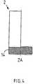
- the Fig. 1 shows the basic structure of the adapter system 1 according to the invention for supplying a periprosthetic fracture.
- the adapter system 1 according to the invention comprises - such as in Fig. 2a to 2c illustrated a set of a plurality of semi-cylindrically cut, distally closed sample tubes 2, which have a proximally accessible interior 3 with different from sample tube to sample sleeve interior shapes 4.
- Fig. 2a to 2c illustrated a set of a plurality of semi-cylindrically cut, distally closed sample tubes 2, which have a proximally accessible interior 3 with different from sample tube to sample sleeve interior shapes 4.
- the sample tubes are pushed onto the end 5 of the shaft 6 of the endoprosthesis and the sample sleeve with the outer shape of the distal end of the shaft largely matching geometry detected.
- Each set of sample tubes 2 is assigned a set of a plurality of implant sleeves 7 with congruent to the interior shapes 4 of the sample tubes 2 adapted interior spaces 8, so that the surgeon can quickly and easily select the correspondingly suitable implant sleeve 7 (see Fig. 6a to 6c . 7a to 7c ).
- the thus determined implant sleeve 7 is on the distal end 5 of the hip stem 6 and the distal end 5 cemented by means of bone cement in the interior 8 of the implant sleeve 7.
- the adapter system 1 further comprises a provided with a cylindrical nail neck 9 nail 10 which is introduced and anchored in the medullary canal of the bone, not shown, and a connecting means 11 in the form of a module consisting of two against the implant sleeve 7 and the nail neck 9 clamping means exciting half-shells 12.1 and 12.2 is formed.
- These half-shells 12.1 and 12.2 jointly define a passage 13 extending in the axial direction AR of the half shells, in the proximal side of which the implant sleeve 7 and in the distal side of the nail neck 9 of the nail 10 rest.
- the outer diameter ADI of the insert 13 in the insert part of the implant sleeve 7 is matched to the inner diameter ID of the bushing 13 and also the outer diameter ADN of the nail neck 9 of the nail 10 is matched to the inner diameter ID of the bushing 13.
- the anchoring of the nail 10 can be done by locking screws or cementing bone cement into the bone.
- the nails 10 are formed variable length and diameter and can be adapted to the individual conditions in the patient.
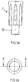
- Fig. 2a to 2c, 3a to 3c and Fig. 4 show examples of sample tubes 2 with various formed in the interior space 3 indoor molds 4, for example, an interior shape for kelch-, parabolic or dome-like shaped ends 5 of the shaft 6 of the endoprosthesis.
- Other external shapes of the shaft 6 such as conical, truncated cone or circular segment-like surfaces or combinations of these Surface composite forms are also part of the invention.
- the sample sleeve 2 consists of a semi-cylindrical body in which the interior shape 4 is open along a plane extending in the direction of the cylinder axis ZA, so that the surgeon can see the position of the inserted into the interior 3 end 5 of the shaft 6 and easily determine that sample tube can, in which the outer shape of the end 5 of the shaft 6 shows a substantial agreement with the interior mold 4.
- a knurled edge 14 which facilitates the sliding and turning of the sample sleeve 2 on the end 5 of the shaft 6.
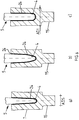
- implant sleeves 7 show the sectional views Fig. 6a to 6c and 7a to 7c with reference to the Fig. 5a and 5b , in whose interiors 8 each of the ends 5 of the shaft 6 of the endoprosthesis are cemented.
- the non-positive cementing with bone cement 24 is indicated along the sectional contour of the interior shape of the implant sleeve by a black edge.
- implant sleeve 7 has a distally mounted plug pin 15 whose outer diameter ADS is adapted to the inner diameter ID of the bushing 13.
- the outer diameter ADI of the remaining part of the cylindrical implant sleeve 7 essentially corresponds to the outer diameter ADD of the leadthrough 13.
- the Fig. 7a to 7c show an alternatively formed cylindrical implant sleeve 7 with uniform outer diameter ADI, in which the cementing of the end 5 of the shaft 6 as in the Fig. 6a to 6c is marked.
- the implant sleeve 7 is located over its entire length L in the passage 13 formed by the half-shells 12.1 and 12.2, whereby the cemented end 5 of the shaft 6 of the prosthesis is uniformly acted upon by the clamping forces.
- the distal end 16 of the cylindrical implant sleeve 7 is positioned in the passage 13, so that act on the cemented region of the end 5 of the shaft 6 only slight clamping forces.
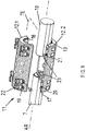
- FIG. 8 shows the adapter system according to the invention in the assembled state, in which the cemented-in end 5 of the shaft 6 is outside the clamping region of the half-shells 12.1 and 12.2.
- the connecting means 11 for the implant sleeve 7 and the nail 10 is shown.
- the connecting means 11 consists of the cylindrical half-shells 12.1 and 12.2, which are of substantially similar design. Both half-shells 12.1 and 12.2 define in the assembled state, the passage 13, the inner wall 17 has a perpendicular to the axial direction AR of the half-shells 12.1 and 12.2 located profiling 18.
- two juxtaposed recesses 19 are each introduced at the edges in the axial direction AR such that the recesses 19 are coaxial with the axial direction AR and perpendicular to are arranged by the half-shells 12.1 and 12.2 virtually spanned division plane TE.
- Each recess 19 is assigned a correspondingly positioned bore 20 with internal thread 21 in the wall 17 of the lower half-shell 12.2, in which guided through the recesses 19 Allen screws 22 can be screwed.
- the half-shells 12.1 and 12.2 form with the Allen screws 22 and the respective corresponding internal threads 21, the clamping means, which is when tightening the Allen screws around the implant sleeve 7 and the nail neck 9 and creates depending on the tightening torque of the Allen screws 21 a corresponding frictional connection.
- the outer diameter ADS of the plug pin 15 or the outer diameter ADI of the cylindrical implant sleeve 7 and the outer diameter ADN of the nail neck 9 of the nail 10 are matched to one another.
- the Allen screws 21 are aligned ventrally and so easily accessible to a later revision from the outside, without having to traumatize large areas of the body's tissue.
- the half-shells may have different lengths L1, L2 or be lengthened by means of module connectors, depending on how the supply of the periprosthetic fracture requires it.
- the upper and lower half-shell 12.1 and 12.2 has-like Fig. 9 clarifies- within the implementation 13 proximal and distal side each a perpendicular from the wall 17 towering stop 23 for the end 5 of the hip stem 6 of the endoprosthesis and the nail neck 9 of the nail 10, whereby a uniform insertion depth for the implant sleeve 7 and the nail neck 9 is achieved in the implementation 13.
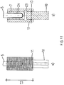
- Fig. 10a, 10b . 11a and 11b show two different lengths half shells in plan view and sectional view, wherein the half shells with the shorter length L1 for an implant sleeve 7 with spigot 15 and the half-shells with the greater length L2 is provided for a cylindrical implant sleeve 7 with constant Au0en pressmesser ADI.
- a common stop 22 is provided for the implant sleeve 7 and the nail neck 9 of the nail 10.
- the invention is not limited in its execution to the aforementioned embodiment. Rather, variants are conceivable, which may in principle include other versions.
- the inventions can be easily adapted for fractures in different areas, e.g. in the area of the hip, knee, shoulder or other endoprostheses with shank.
Description
Die Erfindung betrifft ein periprothetisches Adapter-System für einen bereits implantierten Schaft einer Endoprothese.The invention relates to a periprosthetic adapter system for an already implanted shaft of an endoprosthesis.
Es ist hinlänglich bekannt, dass postoperative periprothetische Frakturen sowohl bei gelockerter als auch bei fest sitzenden Endoprothesen auftreten können.
Durch eine progrediente Knochenresorption kommt es oftmals zu einer Aufweitung der Markhöhle, wodurch günstige Biegemomente zwischen dem Schaft und der Prothesenspitze entstehen, die eine Lockerung der Prothese zur Folge haben und Ermüdungsbrüche sowie Frakturen begünstigen können.
Ursachen für Frakturen bei fest sitzender Prothese sind beispielsweise schwerere Traumatisierungen infolge von Stürzen im Haushalt, Verkehrsunfälle, Stürze aus größerer Höhe, unkontrollierte Stürze aufgrund von Nebenerkrankungen oder Revisionseingriffe.It is well known that postoperative periprosthetic fractures can occur in both loose and tight-fitting endoprostheses.
Progressive bone resorption often leads to an expansion of the medullary cavity, resulting in favorable bending moments between the shaft and the tip of the prosthesis, which result in a loosening of the prosthesis and can promote fatigue fractures and fractures.
Causes of fractures in fixed prosthesis are, for example, severe trauma as a result of falls in the home, traffic accidents, falls from larger Height, uncontrolled falls due to side-diseases or revision surgery.
Aus der
Dieser bekannte Stand der Technik hat den Nachteil, dass eine vollständige Revision des ansonsten fest sitzenden Hüftschaftes der Prothese mit all seinen Beeinträchtigungen für den Patienten durchgeführt werden muss, damit ein mit einer entsprechend eingebrachten Durchgangsbohrung versehener Hüftschaft zur starren Ankopplung des distalen Femurnagels bereitsteht.
Des Weiteren können bei einer späteren Revision erhebliche Probleme bei der Lösung der starren Ankopplung auftreten, weil sich die Verriegelungsschrauben nur nach Extension von Weich-, Muskel- und Sehnenteilen mit entsprechender Traumatisierung des Patienten entfernen lassen.From the
This known prior art has the disadvantage that a complete overhaul of the otherwise firmly seated hip stem of the prosthesis with all its impairments for the patient must be performed so that a hip stem provided with a correspondingly inserted through bore is provided for the rigid coupling of the distal femoral nail.
Furthermore, at a later revision considerable problems in solving the rigid coupling occur because the locking screws can be removed only after extension of soft, muscular and tendon parts with appropriate traumatization of the patient.
Des Weiteren ist aus der
Die
Die
- a) einen oberen Endabschnitt mit einen an einen runden Kopfabschnitt angepassten Hals, welcher in die Hüftpfanne des Patienten eingesetzt ist, einem Mittelabschnitt mit vorderen und hinteren Seiten und einem unteren Schaftabschnitt zum angepassten Einsetzen in den intramedullären Kanal des Femur des Patienten,
- b) entfernbare bezüglich am Hals und Schaft proximale und distale befestigbare Verlängerungselemente zum selektiven Anpassen der Prothese an die benachbarte Gelenkpfanne und das Oberschenkelknochengewebe durch selektives Erhöhen des Prothesenhals,
- c) Haltemittel für jedes Teil zum Befestigen des entsprechenden Teils am Prothesenkörper, wobei die Haltemittel entsprechende kegelstumpfförmige Flächen an jedem Verlängerungselement und am Prothesenkörper aufweisen, und
- d) wobei der Prothesenkörper eine erste kegelstumpfförmige Fläche auf dem Prothesenhals und eine zweite kegelstumpfförmige Fläche am oberen Endabschnitt des Schaftes hat.
- a) an upper end portion having a neck adapted to a round head portion which is inserted into the acetabulum of the patient, a central portion having anterior and posterior sides and a lower shaft portion adapted for insertion into the intramedullary canal of the patient's femur;
- b) removable neck and shaft proximal and distal attachable extension members for selectively fitting the prosthesis to the adjacent articular and femoral tissue by selectively elevating the neck of the prosthesis;
- c) holding means for each part for securing the corresponding part to the prosthesis body, the holding means having corresponding frusto-conical surfaces on each extension element and the prosthesis body, and
- d) wherein the prosthesis body has a first frusto-conical surface on the neck of the prosthesis and a second frusto-conical surface on the upper end portion of the shaft.
Weiterhin ist aus der
Bei diesem Stand der Technik liegt der Erfindung die Aufgabe zugrunde, ein periprothetisches Adapter-System für einen bereits implantierten Schaft einer Endoprothese anzugeben, das den Sitz des Schaftes der Prothese im Knochen stabilisiert und zugleich die postoperative Versorgung von periprothetischen Frakturen unter Reduzierung der Belastungen für den Patienten verbessert wird.In this prior art, the present invention seeks to provide a periprosthetic adapter system for an already implanted shaft of an endoprosthesis, which stabilizes the seat of the shaft of the prosthesis in the bone and at the same time the postoperative care of periprosthetic fractures while reducing the burden on the Patients is improved.
Diese Aufgabe wird durch das erfindungsgemäße Adapter-System der eingangs genannten Art mit den Merkmalen des Anspruches 1 gelöst.This object is achieved by the adapter system according to the invention of the aforementioned type with the features of claim 1.
Vorteilhafte Ausgestaltungen des Adapter-Systems sind den Unteransprüchen entnehmbar.Advantageous embodiments of the adapter system are the dependent claims.
Grundgedanke der erfindungsgemäßen Lösung ist es, den im Knochen befindlichen Schaft der Endoprothese durch das Adapter-System mit einem im Knochen eingebrachten distal verriegelbaren Nagel zu verbinden und dadurch die Verankerungslänge des Schaftes im Knochen wirksam zu erhöhen. Dies gelingt durch das Adapter-System, welches umfasst:
- a) einen Satz einer Vielzahl von zylindrischen, hohl ausgebildeten Probehülsen mit jeweils unterschiedlichen, wenigstens hälftig in Richtung Zylinderachse angeschnittenen Innenraumformen zum Ermitteln der mit der Außenform des distalen Endes des Schaftes weitgehend übereinstimmenden Geometrie,
- b) einen Satz von distal geschlossenen, aber proximal offenen mit dem Satz von Probehülsen mindestens in der Innenraumform übereinstimmenden Implantatshülsen zur Auswahl der geeigneten Implantatshülse für die Aufnahme und eine kraftschlüssige Einbettung des distalen Endes des Schaftes in die Implantatshülse mittels Knochenzement,
- c) einen in den Knochen eingesetzten Nagel mit einem zylindrischen Nagelhals und
- c) ein Verbindungsmittel für das in die Implantatshülse einzementierte Ende des Schaftes und den Nagel in Form eines an sich bekannten Moduls aus mindestens zwei in Achsrichtung des Moduls geteilte, lösbar miteinander verbundene Halbschalen, die miteinander eine sich axial erstreckende Durchführung zum Einführen des distalen Endes der Implantatshülse und des proximalen Nagelhalses ausbilden, wobei die Halbschalen durch senkrecht zur Achsrichtung positionierte Spannmittel den Nagelhals und die Implantatshülse in der Durchführung spannbackenartig fixieren.
- a) a set of a plurality of cylindrical, hollow trained test tubes each having different, at least half in the direction of the cylinder axis truncated interior shapes for determining the largely matching with the outer shape of the distal end of the shaft geometry,
- b) a set of distally closed but proximally open implant sleeves matching the set of trial sleeves at least in the interior shape for selecting the appropriate implant sleeve for receiving and frictionally embedding the distal end of the shaft into the implant sleeve by bone cement;
- c) a nail inserted into the bone with a cylindrical nail neck and
- c) a connecting means for the cemented into the implant sleeve end of the shaft and the nail in the form of a known module of at least two divided in the axial direction of the module, detachably interconnected half shells together with an axially extending passage for insertion of the distal end of the Form implant sleeve and the proximal nail neck, wherein the half-shells fix by clamping means perpendicular to the axial direction positioned clamping means the nail neck and the implant sleeve in the implementation.
Dies ist mit dem außerordentlichen Vorteil verbunden, dass insbesondere Frakturen im Bereich der Schaftspitze ohne Revision des Schaftes versorgt werden können.This is associated with the extraordinary advantage that in particular fractures in the area of the shaft tip can be supplied without revision of the shaft.
Aus der Vielzahl von Probehülsen wird diejenige Hülse durch Aufsetzen der hohlen Probehülse auf das Schaftende ermittelt, die einen nahen Formschluß der Außenform des distalen Endes des Schaftes mit der Innenform des Hohlraumes der Probehülse gewährleistet, und dadurch die geeignete Implantatshülse bestimmt, in die das Schaftende eingesetzt und einzementiert wird.From the plurality of sample tubes that sleeve is determined by placing the hollow sample tube on the shaft end, which ensures a close fit of the outer shape of the distal end of the shaft with the inner shape of the cavity of the sample sleeve, and thereby determines the appropriate implant sleeve, in which inserted the shaft end and cemented.
Von besonderem Vorteil ist weiterhin, wenn die Außendurchmesser der ausgewählten Implantatshülse und des zylindrischen Nagelhalses an den jeweiligen Innendurchmesser der aus den beiden Halbschalen des Verbindungsmittels gebildeten Durchführung angepasst ist. Es ist aber auch möglich, den Außendurchmesser des Nagelhalses auf den Innendurchmesser der Durchführung durch eine auf den zylindrischen Nagelhals aufgeschobene und fixierte Reduzierhülse einzustellen, ohne die Erfindung zu verlassen.It is furthermore of particular advantage if the outside diameter of the selected implant sleeve and of the cylindrical nail neck is adapted to the respective inside diameter of the bushing formed from the two half-shells of the connecting means. However, it is also possible to adjust the outer diameter of the nail neck to the inner diameter of the passage through a slid onto the cylindrical nail neck and fixed reducing sleeve, without departing from the invention.
In einer weiteren bevorzugten Ausgestaltung des erfindungsgemäßen Adapter-Systems sind die Innenräume der Probe- und Implantatshülsen eines Satzes mit Innenraumformen versehen, die in Form und Geometrie an das Schaftende handelsüblicher Endoprothesen angepasst sind.
Die Innenraumform kann vorzugsweise aus zylindrischen, kegel-, kegelstumpf-, parabel-, kreissegment-, halbkugelförmigen Flächen oder aus entsprechend zusammengesetzten Flächen gebildet sein, wodurch es möglich wird, die verschiedenartig ausgebildeten Schaftenden unterschiedlicher Prothesen an das erfindungsgemäße Adapter-System kraftschlüssig anzudocken.In a further preferred embodiment of the adapter system according to the invention, the interiors of the trial and implant sleeves of a set are provided with interior shapes that are adapted in shape and geometry to the shaft end of commercially available endoprostheses.
The interior shape may preferably be formed of cylindrical, conical, truncated, parabolic, kreissegment-, hemispherical surfaces or from correspondingly assembled surfaces, whereby it is possible to frictionally dock the differently shaped shaft ends of different prostheses to the adapter system according to the invention.
In einer weiteren bevorzugten Ausführungsform der Erfindung haben die Implantatshülsen unterschiedlich axiale Längen, Außendurchmesser und Innenraumformen, denen jeweils deckungsgleiche Probehülsen zum Ermitteln eines formschlußnahen Sitzes des Schaftendes in der Implantatshülse zugeordnet sind.
Dies stellt sicher, dass der Chirurg die geeignete Implantatshülse schnell und problemlos während der Operation feststellen kann.In a further preferred embodiment of the invention, the implant sleeves have different axial lengths, outer diameters and interior shapes, which are each assigned congruent sample tubes for determining a close-fit fit of the shaft end in the implant sleeve.
This ensures that the surgeon can quickly and easily identify the appropriate implant sleeve during surgery.
Bei einer weiteren vorteilhaften Weiterbildung der Erfindung sind neben den Implantatshülsen auch die Module des Verbindungsmittels längenvariabel, so dass das erfindungsgemäße Adapter-System gut an die verschiedenartigen Bedingungen der einzelnen Patienten anpassbar ist und eine individuell deutlich vergrößerte Längenvariabilität für die Versorgung periprothetischer Frakturen besitzt.
Diese Längenvariabilität kann weiter dadurch verbessert werden, wenn zum Verbinden von Modulen gleicher oder unterschiedlicher Länge ein Modulverbinder vorgesehen wird, dessen Außendurchmesser auf den Innendurchmesser der Durchführung abgestimmt ist.In a further advantageous embodiment of the invention, in addition to the implant sleeves and the modules of the connecting means are variable in length, so that the adapter system according to the invention is well adapted to the various conditions of each patient and has individually significantly increased length variability for the treatment of periprosthetic fractures.
This length variability can be further improved if, for connecting modules of the same or different lengths, a module connector is provided whose outer diameter is matched to the inner diameter of the bushing.
In einer weiteren Ausgestaltung der Erfindung besitzen alle Flächen der Implantatshülsen, vorzugsweise die Flächen der Innenraumform, eine raue Oberfläche zum Verbessern der Haftkraft des Knochenzements bei Einzementieren des Schaftendes der Prothese in die Implantatshülse.In a further embodiment of the invention, all surfaces of the implant sleeves, preferably the surfaces of the interior mold, have a rough surface for improving the adhesive force of the bone cement when cementing the shaft end of the prosthesis into the implant sleeve.
Alle Teile des erfindungsgemäßen Adapter-Systems bestehen aus einem körperverträglichen und beständigen, vorzugsweise metallischen Werkstoff, beispielsweise Titan, Tantal, Niob oder deren Legierungen bzw. moderne Implantatskunststoffe wie Peek.All parts of the adapter system according to the invention consist of a biocompatible and durable, preferably metallic material, for example titanium, tantalum, niobium or their alloys or modern implant plastics such as Peek.
Weitere Vorteile und Einzelheiten ergeben sich aus der nachfolgenden Beschreibung unter Bezugnahme auf die beigefügten Zeichnungen.Further advantages and details will become apparent from the following description with reference to the accompanying drawings.
Die Erfindung soll nachstehend an einem Ausführungsbeispiel näher erläutert werden.The invention will be explained in more detail below using an exemplary embodiment.
-
Fig. 1 eine Explosionsdarstellung des erfindungsgemäßen Adapter-Systems,Fig. 1 an exploded view of the adapter system according to the invention, -
Fig. 2a bis 2c eine Vorderansicht der Prüfhülsen mit Beispielen unterschiedlicher Innenraumformen,Fig. 2a to 2c a front view of the test tubes with examples of different interior shapes, -
Fig. 3a bis 3c eine Draufsicht gemäß denFiguren 2a bis 2c ,Fig. 3a to 3c a plan view according to theFIGS. 2a to 2c . -
Fig. 4 eine Seitenansicht einer Probehülse,Fig. 4 a side view of a sample sleeve, -
Fig. 5a und 5b eine Seitenansicht bzw. Draufsicht einer Implantatshülse mit einem distal angeordneten Steckzapfen, der einen gegenüber der Implantatshülse geringeren Durchmesser aufweist,Fig. 5a and 5b a side view and top view of an implant sleeve with a distally arranged plug-in pin, which has a smaller diameter compared to the implant sleeve, -
Fig. 6a bis 6c einen Schnitt gemäß Linie A-A inFig. 5b mit verschiedenen Innenraumformen,Fig. 6a to 6c a section along line AA inFig. 5b with different interior shapes, -
Fig. 7a bis 7c eine Schnittdarstellung einer zylindrischen Implantatshülse mit verschiedenen Innenraumformen,Fig. 7a to 7c a sectional view of a cylindrical implant sleeve with different interior shapes, -
Fig. 8 eine perspektivische Darstellung des erfindungsgemäßen Adapter-Systems im zusammengesetzten Zustand,Fig. 8 a perspective view of the adapter system according to the invention in the assembled state, -
Fig. 9 eine perspektivische Darstellung des in Form eines Modules aus zwei Halbschalen zusammengesetzten Verbindungsmittels mit Innenanschlägen für das Schaftende der Prothese und den zylindrischen Nagelhals des Nagels,Fig. 9 a perspective view of the compound in the form of a module of two half-shells connecting means with internal stops for the shaft end of the prosthesis and the cylindrical nail neck of the nail, -
Fig. 10a und11a eine Seitenansicht,Fig. 10b und11b eine Schnittdarstellung des erfindungsgemäßen Adapter-Systems mit einem gemeinsamen Anschlag für die Implantatshülse und den zylindrischen Nagelhals.Fig. 10a and11a a side view,Fig. 10b and11b a sectional view of the adapter system according to the invention with a common stop for the implant sleeve and the cylindrical nail neck.
Die
Das erfindungsgemäße Adapter-System 1 umfasst - wie beispielsweise in
Jedem Satz von Probehülsen 2 ist ein Satz einer Vielzahl von Implantatshülsen 7 mit deckungsgleich an die Innenraumformen 4 der Probehülsen 2 angepassten Innenräumen 8 zugeordnet, so dass der Chirurg schnell und problemlos die entsprechend geeignete Implantatshülse 7 auswählen kann (siehe
Die so ermittelte Implantatshülse 7 wird auf das distale Ende 5 des Hüftschaftes 6 aufgesetzt und das distale Ende 5 mittels Knochenzement im Innenraum 8 der Implantatshülse 7 einzementiert.
Das erfindungsgemäße Adapter-System 1 umfasst weiterhin einen mit einem zylindrischen Nagelhals 9 versehenen Nagel 10, der in den Knochenmarkkanal des nicht dargestellten Knochens eingebracht und verankert wird, und ein Verbindungsmittel 11 in Form eines Moduls, das aus zwei gegen die Implantatshülse 7 und den Nagelhals 9 mittels Spannmittel spannende Halbschalen 12.1 und 12.2 gebildet ist. Diese Halbschalen 12.1 und 12.2 definieren gemeinsam eine in Achsrichtung AR der Halbschalen verlaufende Durchführung 13, in deren proximalen Seite die Implantatshülse 7 und in deren distalen Seite der Nagelhals 9 des Nagels 10 einliegt.
Der Außendurchmesser ADI des in der Durchführung 13 einliegenden Teils der Implantatshülse 7 ist auf den Innendurchmesser ID der Durchführung 13 und ebenso ist der Außendurchmesser ADN des Nagelhalses 9 des Nagels 10 auf den Innendurchmesser ID der Durchführung 13 abgestimmt.
Die Verankerung des Nagels 10 kann durch Verriegelungsschrauben oder Einzementieren mit Knochenzement im Knochen erfolgen. Die Nägel 10 sind längen- und durchmesservariabel ausgebildet und können so an die individuellen Bedingungen beim Patienten angepasst werden.The
The adapter system 1 according to the invention comprises - such as in
Each set of
The thus determined
The adapter system 1 according to the invention further comprises a provided with a
The outer diameter ADI of the
The anchoring of the
Die
An der distal geschlossenen Probehülse 2 befindet sich ein gerändelter Rand 14, der das Aufschieben und Drehen der Probehülse 2 auf das Ende 5 des Schaftes 6 erleichtert.The
At the distal
Beispiele für Implantatshülsen 7 zeigen die Schnittdarstellungen
Die in
Dies ermöglicht es, die Halbschalen 12.1 und 12.2 ausschließlich gegen den Steckzapfen 15 zu spannen, so dass keine Spannkräfte auf das in im Innenraum 8 der Implantatshülse 7 einzementierte Ende 5 des Hüftschaftes übertragen werden.
Der Außendurchmesser ADI des übrigen Teils der zylindrischen Implantatshülse 7 entspricht im Wesentlichen dem Außendurchmesser ADD der Durchführung 13.
Die
Natürlich ist aber auch möglich, dass nur das distale Ende 16 der zylindrischen Implantatshülse 7 in der Durchführung 13 positioniert wird, so dass auf den einzementierten Bereich des Endes 5 des Schaftes 6 lediglich geringfügige Einspannkräfte wirken.Examples of
In the
This makes it possible to clamp the half-shells 12.1 and 12.2 exclusively against the plug-in
The outer diameter ADI of the remaining part of the
The
Of course, it is also possible that only the distal end 16 of the
Die
In der
Der Außendurchmesser ADS des Steckzapfens 15 bzw. der Außendurchmesser ADI der zylindrischen Implantatshülse 7 und der Außendurchmesser ADN des Nagelhalses 9 des Nagels 10 sind aufeinander entsprechend abgestimmt.
Die Imbusschrauben 21 sind nach ventral ausgerichtet und so einer späteren Revision problemlos von außen zugänglich, ohne große Bereiche des körpereigenen Gewebes traumatisieren zu müssen.
Die Halbschalen können unterschiedliche Längen L1, L2 besitzen oder mittels Modulverbinder verlängert werden, je nach dem wie es die Versorgung der periprothetischen Fraktur erfordert.
Die obere und untere Halbschale 12.1 bzw. 12.2 weist -wie
The outer diameter ADS of the
The Allen screws 21 are aligned ventrally and so easily accessible to a later revision from the outside, without having to traumatize large areas of the body's tissue.
The half-shells may have different lengths L1, L2 or be lengthened by means of module connectors, depending on how the supply of the periprosthetic fracture requires it.
The upper and lower half-shell 12.1 and 12.2 has-like
Die
In die Halbschalen 12.1 und 12.2 ist für die Implantatshülse 7 und den Nagelhals 9 des Nagels 10 ein gemeinsamer Anschlag 22 vorgesehen.The
In the half-shells 12.1 and 12.2 a
Alle Teile des erfindungsgemäßen Adapter-System bestehen mit Ausnahme der Imbusschrauben aus Titan, Niob oder deren Legierungen bzw. Implantatskunststoffe wie Peek.All parts of the adapter system according to the invention, with the exception of the Allen screws, consist of titanium, niobium or their alloys or implant plastics such as peek.
Die Erfindung beschränkt sich in ihrer Ausführung nicht auf das vorgenannte Ausführungsbeispiel. Vielmehr sind Varianten denkbar, welche grundsätzlich andere Ausführungen beinhalten können. Die Erfindungen lässt sich problemlos für Frakturen in unterschiedlichen Bereichen wie z.B. im Bereich der Hüfte, des Knies, der Schulter oder anderen Endoprothesen mit Schaft einsetzen.The invention is not limited in its execution to the aforementioned embodiment. Rather, variants are conceivable, which may in principle include other versions. The inventions can be easily adapted for fractures in different areas, e.g. in the area of the hip, knee, shoulder or other endoprostheses with shank.
- Adapter-SystemAdapter system
- 11
- PrüfhülsenPrüfhülsen
- 22
- Innenraum von 2Interior of 2
- 33
- Innenraumgeometrie von 3Interior geometry of 3
- 44
- Ende von 6End of 6
- 55
- Schaft der EndoprotheseShank of the endoprosthesis
- 66
- Implantatshülsenimplant sleeves
- 77
- Innenraum von 7Interior of 7
- 88th
- Nagelhals von 10Nail neck of 10
- 99
- Nagelnail
- 1010
- Verbindungsmittelconnecting means
- 1111
- Obere Halbschale von 11Upper half shell of 11
- 12.112.1
- Untere Halbschale von 11Lower half shell of 11
- 12.212.2
- Durchführungexecution
- 1313
- Gerändelter Rand von 2Knurled edge of 2
- 1414
- Steckzapfen an 7Plug on 7
- 1515
- Distales Ende von 7Distal end of 7
- 1616
- Innere Wandung von 12.1, 12.2Inner wall of 12.1, 12.2
- 1717
- Profilierungprofiling
- 1818
- Ausnehmungen in 12.1Recesses in 12.1
- 1919
- Bohrungen in 12.2Drilling in 12.2
- 2020
- Innengewinde in 20Internal thread in 20
- 2121
- ImbusschraubenAllen screws
- 2222
- Anschlagattack
- 2323
- Knochenzementbone cement
- 2424
- Achsrichtung von 11Axial direction of 11
- ARAR
- Außendurchmesser von 7Outer diameter of 7
- ADIADI
- Außendurchmesser von 11Outer diameter of 11
- ADDADD
- Durchmesser des NagelhalsesDiameter of the nail neck
- ADNADN
- Durchmesser von 15Diameter of 15
- ADSADS
- Innendurchmesser von 13Inner diameter of 13
- IDID
- Länge von 7Length of 7
- LL
- Länge von 12.1, 12.2Length of 12.1, 12.2
- L1, L2L1, L2
- Teilungsebeneparting plane
- TETE
- Zylinderachsecylinder axis
- ZAZA
Claims (13)
- A periprosthetic adapter system for an implanted stem (6) of an endoprosthesis, characterised in that the adapter system (1) comprises:a) a set of a plurality of cylindrical, hollow test sheaths (2) in each case with different interior shapes (4) cut at least halfway in the direction of the cylinder axis (ZA) for determining the geometry largely corresponding to the external shape of the distal end (5) of the stem (6),b) a set of distally closed but proximally open implant sheaths (7) corresponding to the set of test sheaths (2) at least in interior shape (4) for selection of the suitable implant sheath for accommodating and embedding the distal end (5) of the stem (6) in noninterlocking manner in the implant sheath using bone cement (24),c) a nail (10) inserted into the bone and having a cylindrical nail neck (9) andd) a connecting means (11) for the end (5) of the stem (6) cemented into the implant sheath (7) and the nail (10) in the form of a module known per se composed of at least two half-shells (12.1, 12.2) which are divided in the axial direction of the module and connected detachably together and which together form an axially extending passage (13) for insertion of the distal end (16) of the implant sheath (7) and of the proximal nail neck (9), the half-shells (12.1, 12.2) fixing the nail neck (9) and the implant sheath (7) in the passage (13) in the manner of clamping jaws by clamping means positioned perpendicular to the axial direction (AR).
- A periprosthetic adapter system according to claim 1, characterised in that the external diameter (AD) of the implant sheath (7) and the external diameter (ADN) of the cylindrical nail neck (9) is adapted to the internal diameter (ID) of the passage (13) of the half-shells (12.1, 12.2).
- A periprosthetic adapter system according to claim 1, characterised in that the implant sheaths (7) have different external diameters (ADI).
- A periprosthetic adapter system according to claim 1, characterised in that the implant sheaths (7) have different axial lengths, external diameters and interior shapes, to which are in each case assigned the test sheaths for establishing a virtually interlocking fit of the end (5) of the stem (6) in the implant sheath (7)
- A periprosthetic adapter system according to claim 1, characterised in that the implant sheaths (7) comprise an insertion pin (15) at the distal end.
- A periprosthetic adapter system according to claim 1, characterised in that the interiors of the test and implant sheaths (2, 7) of a set are provided with interior shapes which are adapted in shape and geometry to the stem end (6) of conventional commercial endoprostheses.
- A periprosthetic adapter system according to claim 6, characterised in that the interior shape is preferably formed from cylindrical, conical, truncated cone-shaped, parabolic, circular segment-shaped or hemispherical surfaces or of appropriately composed surfaces.
- A periprosthetic adapter system according to claim 1, characterised in that the interior shape (4) has a roughened surface for improving the adhesive force of the bone cement.
- A periprosthetic adapter system according to claim 1, characterised in that the half-shells (12.1, 12.2) are variable in length and achieve a variability of length individually adaptable to periprosthetic fractures.
- A periprosthetic adapter system according to claim 1, characterised in that, to connect modules of identical or different length, a module connector is provided, the external diameter of which is matched to the internal diameter (ID) of the passage (13).
- A periprosthetic adapter system according to claim 1, characterised in that the modules of different length are of identical diameter.
- A periprosthetic adapter system according to claim 1, characterised in that a reducing bushing is provided to adapt the diameter of the nail neck to the internal diameter (ID) of the passage (13).
- A periprosthetic adapter system according to claim 1, characterised in that all the parts of the adapter system consist of a biocompatible, durable, preferably metallic material, for example titanium, tantalum, niobium or the alloys thereof or modern implant plastics such as PEEK.
Applications Claiming Priority (2)
| Application Number | Priority Date | Filing Date | Title |
|---|---|---|---|
| DE201210001395 DE102012001395A1 (en) | 2012-01-26 | 2012-01-26 | Adapter system for an endoprosthesis |
| PCT/DE2013/000032 WO2013110259A1 (en) | 2012-01-26 | 2013-01-17 | Adapter system for an endoprosthesis |
Publications (2)
| Publication Number | Publication Date |
|---|---|
| EP2806830A1 EP2806830A1 (en) | 2014-12-03 |
| EP2806830B1 true EP2806830B1 (en) | 2016-06-15 |
Family
ID=47826779
Family Applications (1)
| Application Number | Title | Priority Date | Filing Date |
|---|---|---|---|
| EP13707536.2A Not-in-force EP2806830B1 (en) | 2012-01-26 | 2013-01-17 | Adapter system for an endoprosthesis |
Country Status (3)
| Country | Link |
|---|---|
| EP (1) | EP2806830B1 (en) |
| DE (1) | DE102012001395A1 (en) |
| WO (1) | WO2013110259A1 (en) |
Families Citing this family (2)
| Publication number | Priority date | Publication date | Assignee | Title |
|---|---|---|---|---|
| TR201610392A2 (en) * | 2016-07-26 | 2016-11-21 | Estas Tibbi Mamuelleri Medikal Cihazlar Otomotiv Imalat Ithalat Ihracat Ve Ticaret Sanayi Anonim Sir | Diaphyseal and Arthrodesis Endoprosthesis System |
| DE102017101815A1 (en) | 2017-01-31 | 2018-08-02 | Olaf Brinkmann | Endoprosthesis and combination of an endoprosthesis and a reinforcing element |
Family Cites Families (7)
| Publication number | Priority date | Publication date | Assignee | Title |
|---|---|---|---|---|
| DE3205577C2 (en) * | 1981-02-23 | 1989-11-02 | Inc. Zweigniederlassung Kiel 2314 Schönkirchen Howmedica International | Endoprosthesis for femoral or tibial articular bone parts and adjacent femoral or tibial bone sections |
| DE3340767A1 (en) * | 1983-11-08 | 1985-05-15 | Mecron Medizinische Produkte Gmbh, 1000 Berlin | KIT FOR A RESECTION PROSTHESIS |
| US4938768A (en) | 1987-03-09 | 1990-07-03 | Henry Ford Hospital | Bone gap bridging and fusing device |
| US5108452A (en) * | 1989-02-08 | 1992-04-28 | Smith & Nephew Richards Inc. | Modular hip prosthesis |
| US7806936B2 (en) * | 2006-10-19 | 2010-10-05 | Depuy Products, Inc. | Bowed femoral sleeve |
| DE102008062226A1 (en) | 2007-12-17 | 2009-08-20 | Wiemer, Christoph, Dr. | Femur fracture caring device, has distal femur nail at its proximal end rigidly couplable to distal end of proximal femur nail that is already provided in femur or hip shaft of hip joint prosthesis |
| DE102008049123B4 (en) * | 2008-09-26 | 2013-06-06 | Merete Medical Gmbh | Modular joint prosthesis |
-
2012
- 2012-01-26 DE DE201210001395 patent/DE102012001395A1/en not_active Withdrawn
-
2013
- 2013-01-17 EP EP13707536.2A patent/EP2806830B1/en not_active Not-in-force
- 2013-01-17 WO PCT/DE2013/000032 patent/WO2013110259A1/en active Application Filing
Also Published As
| Publication number | Publication date |
|---|---|
| EP2806830A1 (en) | 2014-12-03 |
| WO2013110259A1 (en) | 2013-08-01 |
| DE102012001395A1 (en) | 2013-08-01 |
Similar Documents
| Publication | Publication Date | Title |
|---|---|---|
| DE102008045291B4 (en) | Knee arthrodesis implant | |
| DE69925443T2 (en) | Modular prosthesis with shaft and sleeve | |
| DE60224470T2 (en) | Hüftimplantataufbau | |
| DE60303749T2 (en) | Humerusschulterprothese | |
| DE102010048052B4 (en) | Nail screw system for osteosynthesis | |
| EP0792127B1 (en) | Joint prosthesis | |
| DE202005020876U1 (en) | Endoprosthesis comprises a shaft, which extends along a primary axis, a distal end piece and a proximal end piece | |
| EP2349110B1 (en) | Modular joint prosthesis | |
| DE112004001893B4 (en) | Conical joint prosthesis | |
| EP2276422B1 (en) | Modular femoral head prosthesis | |
| WO2010046470A1 (en) | Manipulation system for selection | |
| EP2806830B1 (en) | Adapter system for an endoprosthesis | |
| EP2066265B1 (en) | Hip implant | |
| EP2898860B1 (en) | Hip joint endoprosthesis system | |
| WO2013060718A1 (en) | Adapter for an implant and knee joint prosthesis | |
| AT502137B1 (en) | Primary shaft for hip joint prosthesis, has longitudinal through-hole, whose distal end is provided with fitting surface whereby recess is locked by a removable fitting piece, by forming cone tip at shaft | |
| EP2846738B1 (en) | Reinforcement implant for a long bone, in particular the femur | |
| DE102005001255B4 (en) | Inverse shoulder joint endoprosthesis with one-piece middle part | |
| DE60031766T2 (en) | SURGICAL CLOSURE DEVICE | |
| DE60128635T2 (en) | Self-locking modular prosthesis with cone and associated method | |
| EP3355835A1 (en) | Vertebral column implant and tools for said implant | |
| EP3666229A1 (en) | Knee joint endoprosthetic set and instruments | |
| AT10321U1 (en) | MULTIPLE JOINT DROPS | |
| DE7723852U (en) | Endoprosthesis for auxiliary, knee or angle joints |
Legal Events
| Date | Code | Title | Description |
|---|---|---|---|
| PUAI | Public reference made under article 153(3) epc to a published international application that has entered the european phase |
Free format text: ORIGINAL CODE: 0009012 |
|
| 17P | Request for examination filed |
Effective date: 20140813 |
|
| AK | Designated contracting states |
Kind code of ref document: A1 Designated state(s): AL AT BE BG CH CY CZ DE DK EE ES FI FR GB GR HR HU IE IS IT LI LT LU LV MC MK MT NL NO PL PT RO RS SE SI SK SM TR |
|
| DAX | Request for extension of the european patent (deleted) | ||
| GRAP | Despatch of communication of intention to grant a patent |
Free format text: ORIGINAL CODE: EPIDOSNIGR1 |
|
| GRAS | Grant fee paid |
Free format text: ORIGINAL CODE: EPIDOSNIGR3 |
|
| INTG | Intention to grant announced |
Effective date: 20151201 |
|
| GRAA | (expected) grant |
Free format text: ORIGINAL CODE: 0009210 |
|
| AK | Designated contracting states |
Kind code of ref document: B1 Designated state(s): AL AT BE BG CH CY CZ DE DK EE ES FI FR GB GR HR HU IE IS IT LI LT LU LV MC MK MT NL NO PL PT RO RS SE SI SK SM TR |
|
| REG | Reference to a national code |
Ref country code: CH Ref legal event code: EP Ref country code: GB Ref legal event code: FG4D Free format text: NOT ENGLISH |
|
| REG | Reference to a national code |
Ref country code: IE Ref legal event code: FG4D Free format text: LANGUAGE OF EP DOCUMENT: GERMAN |
|
| REG | Reference to a national code |
Ref country code: AT Ref legal event code: REF Ref document number: 806095 Country of ref document: AT Kind code of ref document: T Effective date: 20160715 |
|
| REG | Reference to a national code |
Ref country code: DE Ref legal event code: R096 Ref document number: 502013003405 Country of ref document: DE |
|
| REG | Reference to a national code |
Ref country code: LT Ref legal event code: MG4D |
|
| REG | Reference to a national code |
Ref country code: NL Ref legal event code: MP Effective date: 20160615 |
|
| PG25 | Lapsed in a contracting state [announced via postgrant information from national office to epo] |
Ref country code: FI Free format text: LAPSE BECAUSE OF FAILURE TO SUBMIT A TRANSLATION OF THE DESCRIPTION OR TO PAY THE FEE WITHIN THE PRESCRIBED TIME-LIMIT Effective date: 20160615 Ref country code: NO Free format text: LAPSE BECAUSE OF FAILURE TO SUBMIT A TRANSLATION OF THE DESCRIPTION OR TO PAY THE FEE WITHIN THE PRESCRIBED TIME-LIMIT Effective date: 20160915 Ref country code: LT Free format text: LAPSE BECAUSE OF FAILURE TO SUBMIT A TRANSLATION OF THE DESCRIPTION OR TO PAY THE FEE WITHIN THE PRESCRIBED TIME-LIMIT Effective date: 20160615 |
|
| PG25 | Lapsed in a contracting state [announced via postgrant information from national office to epo] |
Ref country code: LV Free format text: LAPSE BECAUSE OF FAILURE TO SUBMIT A TRANSLATION OF THE DESCRIPTION OR TO PAY THE FEE WITHIN THE PRESCRIBED TIME-LIMIT Effective date: 20160615 Ref country code: GR Free format text: LAPSE BECAUSE OF FAILURE TO SUBMIT A TRANSLATION OF THE DESCRIPTION OR TO PAY THE FEE WITHIN THE PRESCRIBED TIME-LIMIT Effective date: 20160916 Ref country code: RS Free format text: LAPSE BECAUSE OF FAILURE TO SUBMIT A TRANSLATION OF THE DESCRIPTION OR TO PAY THE FEE WITHIN THE PRESCRIBED TIME-LIMIT Effective date: 20160615 Ref country code: NL Free format text: LAPSE BECAUSE OF FAILURE TO SUBMIT A TRANSLATION OF THE DESCRIPTION OR TO PAY THE FEE WITHIN THE PRESCRIBED TIME-LIMIT Effective date: 20160615 Ref country code: SE Free format text: LAPSE BECAUSE OF FAILURE TO SUBMIT A TRANSLATION OF THE DESCRIPTION OR TO PAY THE FEE WITHIN THE PRESCRIBED TIME-LIMIT Effective date: 20160615 Ref country code: HR Free format text: LAPSE BECAUSE OF FAILURE TO SUBMIT A TRANSLATION OF THE DESCRIPTION OR TO PAY THE FEE WITHIN THE PRESCRIBED TIME-LIMIT Effective date: 20160615 |
|
| REG | Reference to a national code |
Ref country code: FR Ref legal event code: PLFP Year of fee payment: 5 |
|
| PG25 | Lapsed in a contracting state [announced via postgrant information from national office to epo] |
Ref country code: IS Free format text: LAPSE BECAUSE OF FAILURE TO SUBMIT A TRANSLATION OF THE DESCRIPTION OR TO PAY THE FEE WITHIN THE PRESCRIBED TIME-LIMIT Effective date: 20161015 Ref country code: EE Free format text: LAPSE BECAUSE OF FAILURE TO SUBMIT A TRANSLATION OF THE DESCRIPTION OR TO PAY THE FEE WITHIN THE PRESCRIBED TIME-LIMIT Effective date: 20160615 Ref country code: IT Free format text: LAPSE BECAUSE OF FAILURE TO SUBMIT A TRANSLATION OF THE DESCRIPTION OR TO PAY THE FEE WITHIN THE PRESCRIBED TIME-LIMIT Effective date: 20160615 Ref country code: SK Free format text: LAPSE BECAUSE OF FAILURE TO SUBMIT A TRANSLATION OF THE DESCRIPTION OR TO PAY THE FEE WITHIN THE PRESCRIBED TIME-LIMIT Effective date: 20160615 Ref country code: CZ Free format text: LAPSE BECAUSE OF FAILURE TO SUBMIT A TRANSLATION OF THE DESCRIPTION OR TO PAY THE FEE WITHIN THE PRESCRIBED TIME-LIMIT Effective date: 20160615 Ref country code: RO Free format text: LAPSE BECAUSE OF FAILURE TO SUBMIT A TRANSLATION OF THE DESCRIPTION OR TO PAY THE FEE WITHIN THE PRESCRIBED TIME-LIMIT Effective date: 20160615 |
|
| PG25 | Lapsed in a contracting state [announced via postgrant information from national office to epo] |
Ref country code: PT Free format text: LAPSE BECAUSE OF FAILURE TO SUBMIT A TRANSLATION OF THE DESCRIPTION OR TO PAY THE FEE WITHIN THE PRESCRIBED TIME-LIMIT Effective date: 20161017 Ref country code: ES Free format text: LAPSE BECAUSE OF FAILURE TO SUBMIT A TRANSLATION OF THE DESCRIPTION OR TO PAY THE FEE WITHIN THE PRESCRIBED TIME-LIMIT Effective date: 20160615 Ref country code: PL Free format text: LAPSE BECAUSE OF FAILURE TO SUBMIT A TRANSLATION OF THE DESCRIPTION OR TO PAY THE FEE WITHIN THE PRESCRIBED TIME-LIMIT Effective date: 20160615 Ref country code: SM Free format text: LAPSE BECAUSE OF FAILURE TO SUBMIT A TRANSLATION OF THE DESCRIPTION OR TO PAY THE FEE WITHIN THE PRESCRIBED TIME-LIMIT Effective date: 20160615 |
|
| REG | Reference to a national code |
Ref country code: DE Ref legal event code: R097 Ref document number: 502013003405 Country of ref document: DE |
|
| PLBE | No opposition filed within time limit |
Free format text: ORIGINAL CODE: 0009261 |
|
| STAA | Information on the status of an ep patent application or granted ep patent |
Free format text: STATUS: NO OPPOSITION FILED WITHIN TIME LIMIT |
|
| 26N | No opposition filed |
Effective date: 20170316 |
|
| PG25 | Lapsed in a contracting state [announced via postgrant information from national office to epo] |
Ref country code: BE Free format text: LAPSE BECAUSE OF NON-PAYMENT OF DUE FEES Effective date: 20170131 Ref country code: DK Free format text: LAPSE BECAUSE OF FAILURE TO SUBMIT A TRANSLATION OF THE DESCRIPTION OR TO PAY THE FEE WITHIN THE PRESCRIBED TIME-LIMIT Effective date: 20160615 |
|
| PG25 | Lapsed in a contracting state [announced via postgrant information from national office to epo] |
Ref country code: SI Free format text: LAPSE BECAUSE OF FAILURE TO SUBMIT A TRANSLATION OF THE DESCRIPTION OR TO PAY THE FEE WITHIN THE PRESCRIBED TIME-LIMIT Effective date: 20160615 |
|
| REG | Reference to a national code |
Ref country code: CH Ref legal event code: PL |
|
| PG25 | Lapsed in a contracting state [announced via postgrant information from national office to epo] |
Ref country code: MC Free format text: LAPSE BECAUSE OF FAILURE TO SUBMIT A TRANSLATION OF THE DESCRIPTION OR TO PAY THE FEE WITHIN THE PRESCRIBED TIME-LIMIT Effective date: 20160615 |
|
| PG25 | Lapsed in a contracting state [announced via postgrant information from national office to epo] |
Ref country code: CH Free format text: LAPSE BECAUSE OF NON-PAYMENT OF DUE FEES Effective date: 20170131 Ref country code: LI Free format text: LAPSE BECAUSE OF NON-PAYMENT OF DUE FEES Effective date: 20170131 |
|
| REG | Reference to a national code |
Ref country code: IE Ref legal event code: MM4A |
|
| PG25 | Lapsed in a contracting state [announced via postgrant information from national office to epo] |
Ref country code: LU Free format text: LAPSE BECAUSE OF NON-PAYMENT OF DUE FEES Effective date: 20170117 |
|
| REG | Reference to a national code |
Ref country code: FR Ref legal event code: PLFP Year of fee payment: 6 |
|
| REG | Reference to a national code |
Ref country code: BE Ref legal event code: MM Effective date: 20170131 |
|
| REG | Reference to a national code |
Ref country code: DE Ref legal event code: R082 Ref document number: 502013003405 Country of ref document: DE Ref country code: DE Ref legal event code: R081 Ref document number: 502013003405 Country of ref document: DE Owner name: ARISTOTECH INDUSTRIES GMBH, DE Free format text: FORMER OWNER: MERETE MEDICAL GMBH, 12247 BERLIN, DE |
|
| PG25 | Lapsed in a contracting state [announced via postgrant information from national office to epo] |
Ref country code: IE Free format text: LAPSE BECAUSE OF NON-PAYMENT OF DUE FEES Effective date: 20170117 |
|
| PG25 | Lapsed in a contracting state [announced via postgrant information from national office to epo] |
Ref country code: MT Free format text: LAPSE BECAUSE OF FAILURE TO SUBMIT A TRANSLATION OF THE DESCRIPTION OR TO PAY THE FEE WITHIN THE PRESCRIBED TIME-LIMIT Effective date: 20160615 |
|
| PG25 | Lapsed in a contracting state [announced via postgrant information from national office to epo] |
Ref country code: AL Free format text: LAPSE BECAUSE OF FAILURE TO SUBMIT A TRANSLATION OF THE DESCRIPTION OR TO PAY THE FEE WITHIN THE PRESCRIBED TIME-LIMIT Effective date: 20160615 |
|
| REG | Reference to a national code |
Ref country code: AT Ref legal event code: MM01 Ref document number: 806095 Country of ref document: AT Kind code of ref document: T Effective date: 20180117 |
|
| PG25 | Lapsed in a contracting state [announced via postgrant information from national office to epo] |
Ref country code: AT Free format text: LAPSE BECAUSE OF NON-PAYMENT OF DUE FEES Effective date: 20180117 |
|
| PG25 | Lapsed in a contracting state [announced via postgrant information from national office to epo] |
Ref country code: HU Free format text: LAPSE BECAUSE OF FAILURE TO SUBMIT A TRANSLATION OF THE DESCRIPTION OR TO PAY THE FEE WITHIN THE PRESCRIBED TIME-LIMIT; INVALID AB INITIO Effective date: 20130117 |
|
| PG25 | Lapsed in a contracting state [announced via postgrant information from national office to epo] |
Ref country code: BG Free format text: LAPSE BECAUSE OF FAILURE TO SUBMIT A TRANSLATION OF THE DESCRIPTION OR TO PAY THE FEE WITHIN THE PRESCRIBED TIME-LIMIT Effective date: 20160615 |
|
| PG25 | Lapsed in a contracting state [announced via postgrant information from national office to epo] |
Ref country code: CY Free format text: LAPSE BECAUSE OF FAILURE TO SUBMIT A TRANSLATION OF THE DESCRIPTION OR TO PAY THE FEE WITHIN THE PRESCRIBED TIME-LIMIT Effective date: 20160615 |
|
| PG25 | Lapsed in a contracting state [announced via postgrant information from national office to epo] |
Ref country code: MK Free format text: LAPSE BECAUSE OF FAILURE TO SUBMIT A TRANSLATION OF THE DESCRIPTION OR TO PAY THE FEE WITHIN THE PRESCRIBED TIME-LIMIT Effective date: 20160615 |
|
| PG25 | Lapsed in a contracting state [announced via postgrant information from national office to epo] |
Ref country code: TR Free format text: LAPSE BECAUSE OF FAILURE TO SUBMIT A TRANSLATION OF THE DESCRIPTION OR TO PAY THE FEE WITHIN THE PRESCRIBED TIME-LIMIT Effective date: 20160615 |
|
| PGFP | Annual fee paid to national office [announced via postgrant information from national office to epo] |
Ref country code: FR Payment date: 20211115 Year of fee payment: 10 |
|
| PGFP | Annual fee paid to national office [announced via postgrant information from national office to epo] |
Ref country code: GB Payment date: 20220228 Year of fee payment: 10 Ref country code: DE Payment date: 20211125 Year of fee payment: 10 |
|
| REG | Reference to a national code |
Ref country code: DE Ref legal event code: R119 Ref document number: 502013003405 Country of ref document: DE |
|
| GBPC | Gb: european patent ceased through non-payment of renewal fee |
Effective date: 20230117 |
|
| PG25 | Lapsed in a contracting state [announced via postgrant information from national office to epo] |
Ref country code: GB Free format text: LAPSE BECAUSE OF NON-PAYMENT OF DUE FEES Effective date: 20230117 Ref country code: DE Free format text: LAPSE BECAUSE OF NON-PAYMENT OF DUE FEES Effective date: 20230801 |
|
| PG25 | Lapsed in a contracting state [announced via postgrant information from national office to epo] |
Ref country code: FR Free format text: LAPSE BECAUSE OF NON-PAYMENT OF DUE FEES Effective date: 20230131 |