EP2806711A1 - Incremental Sheet Forming for Fabrication of Cold Sprayed Smart Susceptor - Google Patents
Incremental Sheet Forming for Fabrication of Cold Sprayed Smart Susceptor Download PDFInfo
- Publication number
- EP2806711A1 EP2806711A1 EP14161463.6A EP14161463A EP2806711A1 EP 2806711 A1 EP2806711 A1 EP 2806711A1 EP 14161463 A EP14161463 A EP 14161463A EP 2806711 A1 EP2806711 A1 EP 2806711A1
- Authority
- EP
- European Patent Office
- Prior art keywords
- smart susceptor
- tool
- susceptor
- smart
- ferromagnetic material
- Prior art date
- Legal status (The legal status is an assumption and is not a legal conclusion. Google has not performed a legal analysis and makes no representation as to the accuracy of the status listed.)
- Granted
Links
- 238000004519 manufacturing process Methods 0.000 title claims abstract description 23
- 239000003302 ferromagnetic material Substances 0.000 claims abstract description 51
- 230000006698 induction Effects 0.000 claims abstract description 44
- 238000010438 heat treatment Methods 0.000 claims abstract description 35
- 229910052751 metal Inorganic materials 0.000 claims abstract description 28
- 239000002184 metal Substances 0.000 claims abstract description 28
- 230000005672 electromagnetic field Effects 0.000 claims abstract description 25
- 238000000034 method Methods 0.000 claims description 49
- 239000000843 powder Substances 0.000 claims description 40
- 230000005294 ferromagnetic effect Effects 0.000 claims description 28
- 230000005291 magnetic effect Effects 0.000 claims description 10
- 238000010288 cold spraying Methods 0.000 abstract description 14
- 239000000203 mixture Substances 0.000 abstract description 10
- 239000007789 gas Substances 0.000 description 19
- 239000002245 particle Substances 0.000 description 13
- 239000000463 material Substances 0.000 description 11
- 239000007921 spray Substances 0.000 description 9
- 241000167857 Bourreria Species 0.000 description 7
- 239000002131 composite material Substances 0.000 description 7
- 239000000919 ceramic Substances 0.000 description 6
- 230000008569 process Effects 0.000 description 6
- 230000015572 biosynthetic process Effects 0.000 description 5
- XEEYBQQBJWHFJM-UHFFFAOYSA-N Iron Chemical compound [Fe] XEEYBQQBJWHFJM-UHFFFAOYSA-N 0.000 description 4
- PXHVJJICTQNCMI-UHFFFAOYSA-N Nickel Chemical compound [Ni] PXHVJJICTQNCMI-UHFFFAOYSA-N 0.000 description 4
- 229920000642 polymer Polymers 0.000 description 4
- 230000008901 benefit Effects 0.000 description 3
- 239000011152 fibreglass Substances 0.000 description 3
- 238000012986 modification Methods 0.000 description 3
- 230000004048 modification Effects 0.000 description 3
- 230000003647 oxidation Effects 0.000 description 3
- 238000007254 oxidation reaction Methods 0.000 description 3
- 230000035699 permeability Effects 0.000 description 3
- 239000000758 substrate Substances 0.000 description 3
- IJGRMHOSHXDMSA-UHFFFAOYSA-N Atomic nitrogen Chemical compound N#N IJGRMHOSHXDMSA-UHFFFAOYSA-N 0.000 description 2
- 229910017052 cobalt Inorganic materials 0.000 description 2
- 239000010941 cobalt Substances 0.000 description 2
- GUTLYIVDDKVIGB-UHFFFAOYSA-N cobalt atom Chemical compound [Co] GUTLYIVDDKVIGB-UHFFFAOYSA-N 0.000 description 2
- 238000007596 consolidation process Methods 0.000 description 2
- 230000007423 decrease Effects 0.000 description 2
- 238000010586 diagram Methods 0.000 description 2
- 229910052742 iron Inorganic materials 0.000 description 2
- 238000012423 maintenance Methods 0.000 description 2
- 238000002844 melting Methods 0.000 description 2
- 230000008018 melting Effects 0.000 description 2
- 229910052759 nickel Inorganic materials 0.000 description 2
- ISWSIDIOOBJBQZ-UHFFFAOYSA-N phenol group Chemical group C1(=CC=CC=C1)O ISWSIDIOOBJBQZ-UHFFFAOYSA-N 0.000 description 2
- 238000000926 separation method Methods 0.000 description 2
- 238000005507 spraying Methods 0.000 description 2
- 238000007751 thermal spraying Methods 0.000 description 2
- VYZAMTAEIAYCRO-UHFFFAOYSA-N Chromium Chemical compound [Cr] VYZAMTAEIAYCRO-UHFFFAOYSA-N 0.000 description 1
- ZOKXTWBITQBERF-UHFFFAOYSA-N Molybdenum Chemical compound [Mo] ZOKXTWBITQBERF-UHFFFAOYSA-N 0.000 description 1
- 229910000831 Steel Inorganic materials 0.000 description 1
- 229910052782 aluminium Inorganic materials 0.000 description 1
- XAGFODPZIPBFFR-UHFFFAOYSA-N aluminium Chemical compound [Al] XAGFODPZIPBFFR-UHFFFAOYSA-N 0.000 description 1
- 238000005452 bending Methods 0.000 description 1
- 230000009286 beneficial effect Effects 0.000 description 1
- 229910010293 ceramic material Inorganic materials 0.000 description 1
- 229910052804 chromium Inorganic materials 0.000 description 1
- 239000011651 chromium Substances 0.000 description 1
- 238000004891 communication Methods 0.000 description 1
- 239000002826 coolant Substances 0.000 description 1
- 238000005336 cracking Methods 0.000 description 1
- 238000013461 design Methods 0.000 description 1
- 230000007613 environmental effect Effects 0.000 description 1
- 239000012530 fluid Substances 0.000 description 1
- 238000009432 framing Methods 0.000 description 1
- 239000001307 helium Substances 0.000 description 1
- 229910052734 helium Inorganic materials 0.000 description 1
- SWQJXJOGLNCZEY-UHFFFAOYSA-N helium atom Chemical compound [He] SWQJXJOGLNCZEY-UHFFFAOYSA-N 0.000 description 1
- 238000007373 indentation Methods 0.000 description 1
- 230000010354 integration Effects 0.000 description 1
- WPBNNNQJVZRUHP-UHFFFAOYSA-L manganese(2+);methyl n-[[2-(methoxycarbonylcarbamothioylamino)phenyl]carbamothioyl]carbamate;n-[2-(sulfidocarbothioylamino)ethyl]carbamodithioate Chemical compound [Mn+2].[S-]C(=S)NCCNC([S-])=S.COC(=O)NC(=S)NC1=CC=CC=C1NC(=S)NC(=O)OC WPBNNNQJVZRUHP-UHFFFAOYSA-L 0.000 description 1
- 239000000155 melt Substances 0.000 description 1
- 229910052750 molybdenum Inorganic materials 0.000 description 1
- 239000011733 molybdenum Substances 0.000 description 1
- 229910052757 nitrogen Inorganic materials 0.000 description 1
- 230000008520 organization Effects 0.000 description 1
- 239000004033 plastic Substances 0.000 description 1
- 238000012545 processing Methods 0.000 description 1
- 238000009419 refurbishment Methods 0.000 description 1
- 125000006850 spacer group Chemical group 0.000 description 1
- 239000010959 steel Substances 0.000 description 1
Images


Classifications
-
- H—ELECTRICITY
- H05—ELECTRIC TECHNIQUES NOT OTHERWISE PROVIDED FOR
- H05B—ELECTRIC HEATING; ELECTRIC LIGHT SOURCES NOT OTHERWISE PROVIDED FOR; CIRCUIT ARRANGEMENTS FOR ELECTRIC LIGHT SOURCES, IN GENERAL
- H05B6/00—Heating by electric, magnetic or electromagnetic fields
- H05B6/02—Induction heating
- H05B6/10—Induction heating apparatus, other than furnaces, for specific applications
- H05B6/105—Induction heating apparatus, other than furnaces, for specific applications using a susceptor
-
- B—PERFORMING OPERATIONS; TRANSPORTING
- B21—MECHANICAL METAL-WORKING WITHOUT ESSENTIALLY REMOVING MATERIAL; PUNCHING METAL
- B21D—WORKING OR PROCESSING OF SHEET METAL OR METAL TUBES, RODS OR PROFILES WITHOUT ESSENTIALLY REMOVING MATERIAL; PUNCHING METAL
- B21D31/00—Other methods for working sheet metal, metal tubes, metal profiles
- B21D31/005—Incremental shaping or bending, e.g. stepwise moving a shaping tool along the surface of the workpiece
-
- B—PERFORMING OPERATIONS; TRANSPORTING
- B29—WORKING OF PLASTICS; WORKING OF SUBSTANCES IN A PLASTIC STATE IN GENERAL
- B29C—SHAPING OR JOINING OF PLASTICS; SHAPING OF MATERIAL IN A PLASTIC STATE, NOT OTHERWISE PROVIDED FOR; AFTER-TREATMENT OF THE SHAPED PRODUCTS, e.g. REPAIRING
- B29C33/00—Moulds or cores; Details thereof or accessories therefor
- B29C33/38—Moulds or cores; Details thereof or accessories therefor characterised by the material or the manufacturing process
-
- C—CHEMISTRY; METALLURGY
- C23—COATING METALLIC MATERIAL; COATING MATERIAL WITH METALLIC MATERIAL; CHEMICAL SURFACE TREATMENT; DIFFUSION TREATMENT OF METALLIC MATERIAL; COATING BY VACUUM EVAPORATION, BY SPUTTERING, BY ION IMPLANTATION OR BY CHEMICAL VAPOUR DEPOSITION, IN GENERAL; INHIBITING CORROSION OF METALLIC MATERIAL OR INCRUSTATION IN GENERAL
- C23C—COATING METALLIC MATERIAL; COATING MATERIAL WITH METALLIC MATERIAL; SURFACE TREATMENT OF METALLIC MATERIAL BY DIFFUSION INTO THE SURFACE, BY CHEMICAL CONVERSION OR SUBSTITUTION; COATING BY VACUUM EVAPORATION, BY SPUTTERING, BY ION IMPLANTATION OR BY CHEMICAL VAPOUR DEPOSITION, IN GENERAL
- C23C24/00—Coating starting from inorganic powder
- C23C24/02—Coating starting from inorganic powder by application of pressure only
- C23C24/04—Impact or kinetic deposition of particles
-
- B—PERFORMING OPERATIONS; TRANSPORTING
- B29—WORKING OF PLASTICS; WORKING OF SUBSTANCES IN A PLASTIC STATE IN GENERAL
- B29C—SHAPING OR JOINING OF PLASTICS; SHAPING OF MATERIAL IN A PLASTIC STATE, NOT OTHERWISE PROVIDED FOR; AFTER-TREATMENT OF THE SHAPED PRODUCTS, e.g. REPAIRING
- B29C33/00—Moulds or cores; Details thereof or accessories therefor
- B29C33/02—Moulds or cores; Details thereof or accessories therefor with incorporated heating or cooling means
- B29C33/06—Moulds or cores; Details thereof or accessories therefor with incorporated heating or cooling means using radiation, e.g. electro-magnetic waves, induction heating
-
- B—PERFORMING OPERATIONS; TRANSPORTING
- B29—WORKING OF PLASTICS; WORKING OF SUBSTANCES IN A PLASTIC STATE IN GENERAL
- B29K—INDEXING SCHEME ASSOCIATED WITH SUBCLASSES B29B, B29C OR B29D, RELATING TO MOULDING MATERIALS OR TO MATERIALS FOR MOULDS, REINFORCEMENTS, FILLERS OR PREFORMED PARTS, e.g. INSERTS
- B29K2995/00—Properties of moulding materials, reinforcements, fillers, preformed parts or moulds
- B29K2995/0003—Properties of moulding materials, reinforcements, fillers, preformed parts or moulds having particular electrical or magnetic properties, e.g. piezoelectric
- B29K2995/0008—Magnetic or paramagnetic
Definitions
- Induction heating systems have been used to provide heat for processes such as fabricating parts or components.
- Induction heating systems typically include a ferromagnetic material that responds to an oscillating electromagnetic field generated by an energized induction coil by generating heat within the ferromagnetic material. Heat is typically conducted from the ferromagnetic element directly to the parts or components.
- a smart susceptor that includes a ferromagnetic element or material may be heated in an induction heating system to provide a fairly stable temperature to heat the parts or components.
- the composition of a smart susceptor is typically configured so that the smart susceptor has a specific Curie temperature and thus, will provide a fairly stable temperature when used in an induction heating.
- U.S. Patent No. 6,566,635 to Matsen el al. discloses applying a magnetically permeable powder to a mesh structure using a hot spray gun to form a susceptor.
- Thermal or hot spraying of a magnetically permeable powder melts the sprayed material prior to contacting a target.
- the thermal application of magnetically permeable powder may limit the composition of powder that may be applied to form a susceptor.
- the thermal application of the magnetically permeable powder may also subject the sprayed susceptor to oxidation.
- the application of the magnetically permeable powder to a mesh structure may also limit the geometrical shape of the formed susceptor.
- the use of a mesh structure may limit the tolerances of the dimensions of the formed susceptor.
- an induction heating smart susceptor may be cold spraying a ferromagnetic material cold on to a surface of a tool that may previously be formed into a desired shape by increment sheet forming.
- an induction heating system for manufacturing a part comprises an induction coil capable of generating an oscillating electromagnetic field and a susceptor positioned in the oscillating electromagnetic field when said induction coil is energized.
- the susceptor comprises a sheet metal component and a ferromagnetic material cold sprayed onto the sheet metal component.
- the sheet metal component is formed to a desired shape by incremental sheet forming.
- the sheet metal component of the system may be approximately 0.01 to 0.03 inches thick.
- the sheet metal component of the system may be non-magnetic.
- the sheet metal component may have a Curie temperature below a Curie temperature of the ferromagnetic material.
- the ferromagnetic material may be cold sprayed onto the tooling component to a thickness of 0.04 to 0.125 inches thick.
- One configuration of a system for forming a cold sprayed smart susceptor comprises a gas control module in communication with a first line and a second line that controls the flow of gas in the first and second lines.
- the system comprises a nozzle connected to the gas control module by the first line and a heater positioned along the first line between the gas control module and the nozzle.
- the system comprises a powder feeder positioned along the second line between the gas control module and the nozzle.
- the flow of gas in the first and second line creates a particle stream of powder out of the nozzle that forms a smart susceptor as it contacts a surface of a tool.
- the surface of the tool may be formed to a desired shape by incremental sheet forming.
- the heater positioned along the first line may heat the gas in the first line to between approximately 400 degrees Celsius to 900 degrees Celsius.
- One configuration of a method of manufacturing a smart susceptor comprises forming a tooling component and cold spraying a ferromagnetic material on a surface of the tooling component.
- the ferromagnetic material has a predetermined Curie temperature based on a composition of the ferromagnetic material.
- Forming the tooling component may comprise forming a non-magnetic sheet of metal to a desired shape using incremental sheet forming.
- Forming the tooling component may comprise forming the tooling component from a ceramic die.
- Forming the tooling component may comprise forming the tooling component from a polymer sheet or a composite sheet.
- Forming the tooling component may comprise forming the tooling component from a sheet of metal having a Curie temperature below the Curie temperature of the ferromagnetic material.
- the method may comprise applying an oscillating electromagnetic field to the ferromagnetic material to release the ferromagnetic material from the surface of the tooling component.
- the method may comprise heating a gas flowing to a nozzle used to spray the ferromagnetic material.
- the method may comprise thermally shocking the tooling component and the ferromagnetic material to release the ferromagnetic material from the surface of the tooling component.
- One configuration of a method of manufacturing a part comprises positioning a smart susceptor adjacent to a part, applying an oscillating electromagnetic field to the smart susceptor to generate eddy currents to heat the smart susceptor, and heating the part with the smart susceptor.
- the smart susceptor is fabricated from cold sprayed ferromagnetic powder disposed on a surface of a tool that has been shaped by incremental sheet forming.
- Positioning the smart susceptor adjacent a part may further comprise positioning the smart susceptor into an induction heating system.
- the method may comprise releasing the smart susceptor from the tool.
- the smart susceptor may be positioned adjacent to the part after releasing the smart susceptor from the tool.
- the configurations described herein relate to a smart susceptor that may be used in an induction heating system for manufacturing a part.
- the smart susceptor may be formed by cold spraying a material such as a ferromagnetic powder onto a surface of a tool or ceramic die. Cold spraying is defined herein as spraying a material at a temperature that is below the melting point of the material being sprayed.
- the tool may be formed into a desired shape by incremental sheet forming.
- the smart susceptor and tool assembly may be positioned within an induction heating system to heat a component by the application of an oscillating electromagnetic field. Alternatively, the smart susceptor may be removed from the surface of the tool and positioned alone within an induction heating system to heat a component by the application of an oscillating electromagnetic field.
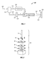
- FIG. 1 shows a schematic of one configuration of a system 100 that may be used to cold spray a ferromagnetic powder 130 onto a surface or substrate 151 of a tool component or a sheet metal component 150 to form a smart susceptor 145.
- a source of gas 105 such as nitrogen or helium, is connected to a gas control module 110 that controls the flow of the gas 105 through a first line 115 connected to a nozzle 135 and through a second line 120 connected to a powder chamber 131 and then to the nozzle 135.
- the gas flowing through the lines 115 and 120 causes ferromagnetic powder 130 located within the powder chamber 131 to be sprayed from the nozzle 135 as a particle stream 140.
- the particle stream 140 travels at a high velocity from the nozzle 135, which may be a supersonic nozzle, and is deposited on a surface or substrate 151 of a sheet metal component or a tool component 150 (hereinafter referred to as a tool) to form a smart susceptor 145.
- the particle stream 140 is sprayed at a temperature that is well below the melting point of the ferromagnetic powder 130.
- the particle stream 140 could be sprayed directly onto a surface of a die to form the smart susceptor 145 on the surface of a die instead of on the surface of a tool 150.
- the particle stream 140 is sprayed in a supersonic gas jet onto the surface or substrate 151 of the tool 150. On impact on the surface 151, the particles of the particle stream 140 undergo plastic deformation due to the high velocity of the particle stream 140 and bond to each other to form the smart susceptor 145.
- the system 100 may include a heater 125 used to heat the gas 105 to a requisite temperature prior to entrance of the gas 105 into the nozzle 135.
- the gas 105 may be heated to between 400 degrees and 900 degrees Celsius prior to entering the nozzle 135 to spray the powder 130 into a particle stream 140.
- the heater 125 is used to accelerate the speed of the particle stream 140, but the heat from the heated gas 105 is not transferred to the metallurgical bonding of the particles of the particle stream 140.
- the ferromagnetic powder 130 used in the cold spray process may be configured to produce a smart susceptor 145 having a desired Curie temperature, as would be recognized by one of ordinary skill in the art having the benefit of this disclosure.
- the cold spraying of the powder 130 as opposed to thermal spraying, may permit the use of a larger number of ferromagnetic powders 130 to produce a smart susceptor 145.
- the ferromagnetic powder 130 may be a mixture of ferromagnetic materials, such as ferromagnetic powders, to produce a smart susceptor 145 having a desired Curie temperature.
- the ferromagnetic powder may be a mixture of nickel, cobalt, and iron powders or other ferromagnetic powders, to achieve a desired Curie temperature.
- the use of a cold spray helps to limit dimension distortion of the smart susceptor due to thermal issues.
- the cold spray of ferromagnetic powder 130 onto a previously shaped surface permits the rapid creation of a smart susceptor 145 having a desired geometric shape. Incremental sheet forming permits the detailed formatting of a surface having tight dimensional tolerances.
- the ferromagnetic powder 130 may be cold sprayed to produce a smart susceptor 145 having a desired thickness, such as between approximately .04 and .125 inches.
- the cold spraying of the smart susceptor 145 as opposed to thermal spraying may permit the smart susceptor 145 to be comprised of a material that is not durable at high temperatures and/or is susceptible to oxidation at high temperatures.
- the use of a susceptor 145 on a surface 151 of a tool 150 may aid in the durability at high temperatures as materials used to form a susceptor, in general, may not be durable and may be susceptible to oxidation at high temperatures.
- the surface 151 of the tool 150 may be shaped by a process, such as incremental sheet forming, into a desired shape, such as a complex geometric shape.
- the cold sprayed smart susceptor 145 may be formed into the same shape as the surface 151 of the tool 150. Incremental sheet forming permits the rapid formation of a tool surface 151 having requisite tolerances.
- FIG. 2 shows components that may be used in system 30 to perform incremental sheet forming.
- a forming tool 31 is used to create small incremental deformations in a workpiece or tool 34 until the tool 34 is formed into the desired geometrical shape.
- the forming tool 31 is connected to a machine (not shown) to perform the deformations.
- the machine may be a computer controlled machine that controls the repeated indentations by the forming tool 31 until the tool 34 is formed to the desired geometrical shape.
- the tool 34 may be held in a rigid fashion between a blankholder 33 and a modular die 35 which may be secured together by fasteners 32.
- a die support 36 may provide sufficient rigidity to the modular die 35.
- Incremental sheet forming permits the rapid, inexpensive, and accurate forming of a tool 34 upon which ferromagnetic powder 130 may be cold sprayed on to form the smart susceptor 145 having a specified geometry.
- Incremental sheet forming may be used on a sheet of metal having a thickness of approximately 0.01 inches to 0.03 inches. Incremental sheet forming may also be used to form a sheet of polymer or a sheet of composite material into a desired geometrical shape.
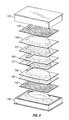
- FIG. 3 shows a workcell 10 in which a cold sprayed smart susceptor 145 (shown in FIG. 4 ) may be placed to heat up a part or component 160 (shown in FIG. 4 ).
- the workcell 10 includes an upper die 11 mounted within an upper strongback 13 and a lower die 12 mounted within a lower strongback 14.
- the strongbacks 13 and 14 are each threaded onto four threaded column supports, or jackscrews 15 allowing adjustment of the relative positions of the dies 11 and 12 and strongbacks 13 and 14.
- the dies 11 and 12 define a die cavity that is shaped to hold a smart susceptor 145 that, in turn, surrounds a part 160.
- a ferromagnetic powder may be cold sprayed directly onto one of the dies 11 and 12 to form the smart susceptor 145 (shown in FIG. 4 ).
- a plurality of induction coils 26 are embedded in the dies 11 and 12, and surround the smart susceptor 145. When energized, the coils 26 generate an oscillating electromagnetic field that causes eddy currents in the smart susceptor 145, which heats up the smart susceptor 145, causing the smart susceptor 145 to generate heat so as to perform a step in manufacturing the part 160, such as forming a metal part, or consolidating a composite part.
- the smart susceptor 145 will continue to heat up until it reaches the Curie temperature of the ferromagnetic material of the smart susceptor 145.
- the Curie temperature of the smart susceptor 145 is determined by the properties of the ferromagnetic materials combined to form the smart susceptor 145. Upon reaching the Curie temperature, the ferromagnetic material of the smart susceptor 145 becomes substantially non-magnetic.
- the induction heating workcell 10 further includes a set of clamping bars 16 that hold the dies 11 and 12 in place against the strongbacks 13 and 14.
- the strongbacks 13 and 14 provide a rigid, flat backing surface for the upper and lower dies 11 and 12, which prevents the dies 11 and 12 from bending and cracking during the manufacturing operation. Additionally, the strongbacks 13 and 14 may serve as stiff plates that keep the dies 11 and 12 together and accurately positioned.
- the strongbacks 13 and 14 may be constructed of steel, aluminum, or any other material capable of handling the loads present during forming or consolidation. Preferably, nonmagnetic materials are used to prevent distortion of the oscillating electromagnetic field produced by the induction coil 26.
- the dies 11 and 12 themselves may be strong enough to withstand the loads present during forming or consolidation.
- Each of the dies 11 and 12 may include a rectangular block of ceramic material reinforced by a set of fiberglass rods 20 and a set of support plates.
- the support plates preferably comprise a set of phenolic boards arranged in the shape of a rectangular box framing each ceramic block.
- a set of nuts 21 are tightened on the threaded ends of the fiberglass rods 20 to apply a compressive load on the phenolic boards.
- the induction coils 26 are embedded into the ceramic blocks and are positioned between the fiberglass rods 20 and surround the die cavity. The coils 26 may also remove thermal energy by serving as a conduit for a coolant fluid.
- the coils 26 may include straight tubing sections 27 connected by flexible tubing sections 28.
- the flexible tubing sections 28 connect the straight tubing sections 27 and may allow the dies 11 and 12 to be separated.
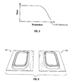
- FIG. 4 shows a pair of dies 155 that may be used to form a part 160 using a cold sprayed smart susceptor 145.
- the smart susceptor 145 is formed by cold spraying ferromagnetic powder 130 onto the surface 151 of a tool 150, or die, that has a desired geometrical shape so that the smart susceptor 145 also is formed with the desired geometrical shape.
- the smart susceptor 145 may then be removed from the tool 150 to form a part 160 in an induction heating system.
- the smart susceptor 145 along with the tool 150 may be inserted into a heat induction system to form a part 160.
- a spacer 156, a die insert 157, and/or a bladder 158 may also be inserted in between the smart susceptor 145 and the part 160 to be formed.
- the dies 155 are formed to create a cavity to hold the part 160 the cold sprayed smart susceptor(s) 145 as well as any additional processing components within an induction heating system.
- the cold sprayed smart susceptor(s) 145 are then heated to impart heat to the part 160 by the application of an oscillating electromagnetic field, as would be appreciated by one of ordinary skill in the art having the benefit of this disclosure.
- the ferromagnetic material 130 of the smart susceptor 145 becomes substantially non-magnetic when it reaches the Curie temperature.
- the magnetic permeability of the ferromagnetic material 130 suddenly decreases when the ferromagnetic material 130 reaches the Curie temperature.
- the sudden drop in magnetic permeability results in a distortion of the eddy currents generated by the induction coil.
- the ferromagnetic material 130 below the Curie temperature may continue to generate eddy currents.
- FIG. 6 shows a cold sprayed smart susceptor 145 that has been separated from a tool 150 used to form the smart susceptor 145 with a desired geometric shape.
- the smart susceptor 145 may be removed from the tool 150 by thermally shocking the smart susceptor 145 and the tool 150.
- the tool 150 and the smart susceptor 145 have different thermal expansion properties and thus, will permit the separation of the two components when thermally shocked.
- the smart susceptor 145 and tool 150 may be heated by various means to separate the smart susceptor 145 from the tool 150 due to their different thermal expansion properties.
- the smart susceptor 145 may be separated from the tool 150 by the application of an oscillating electromagnetic field to the smart susceptor 145 and the tool 150.
- the cold spraying of ferromagnetic powder 130 to form a smart susceptor 145 permits the formation of a smart susceptor 145 with a desired geometric shape that may be used alone in an induction heating system after removing the smart susceptor 145 from the formation tool 150.
- the formation tool 150 may aid in the durability of the smart susceptor 145 at high temperatures.
- FIG. 7 shows a method 200 of manufacturing a smart susceptor that includes the step 205 of forming a tooling component.
- the tooling component may be formed by incremental sheet forming, as discussed above. Incremental sheet forming may be used to form a tool out of sheet metal, a polymer sheet, or a composite sheet.
- the tooling component may be a ceramic die.
- the method 200 includes the step 210 of cold spraying a ferromagnetic material to a surface of the tooling component.
- the ferromagnetic material may be a ferromagnetic powder having a predetermined Curie temperature.
- the ferromagnetic powder may be a mixture of various powders, such as cobalt, nickel, chromium, Molybdenum, Manganese, iron, and/or other ferromagnetic materials having a predetermined Curie temperature based on the composition of the mixture of powders.
- the method 200 may optionally include a step 215 of applying an oscillating electromagnetic field to the ferromagnetic material to release the ferromagnetic material from the surface of the tooling component.
- the application of an oscillating electromagnetic field to the ferromagnetic material may add some vibrational forces that aid in the separation in addition to the difference in thermal expansion.
- the method 200 may optionally include a step 220 of thermally shocking the tooling component and the ferromagnetic material to release the ferromagnetic material from the surface of the tooling component.
- FIG. 8 shows a method 250 of manufacturing a part that includes the step 255 of incremental sheet forming a tool of a desired shape.
- the part may comprise a composite part.
- the method 250 includes the optional step 260 of heating a gas flowing to a nozzle used to spray ferromagnetic powder.
- the method 250 includes the step 265 of cold spraying a ferromagnetic powder onto a surface of the tool having the desired shape to form a smart susceptor.
- the method 250 includes the optional step 270 of releasing the smart susceptor from the surface of the tool.
- the method 250 includes the step 275 of positioning the smart susceptor adjacent to a part and the step 280 of applying an oscillating electromagnetic field to the smart susceptor to generate eddy currents to heat up the smart susceptor.
- the method 250 includes the step 285 of heating up the part with the heat generated from the smart susceptor.
- exemplary method 300 may include specification and design 304 of the aircraft 302 and material procurement 306.
- component and subassembly manufacturing 308 and system integration 310 of the aircraft 302 takes place.
- the aircraft 302 may go through certification and delivery 312 in order to be placed in service 314.
- routine maintenance and service 316 which may also include modification, reconfiguration, refurbishment, and so on).
- a system integrator may include without limitation any number of aircraft manufacturers and major-system subcontractors; a third party may include without limitation any number of vendors, subcontractors, and suppliers; and an operator may be an airline, leasing company, military entity, service organization, and so on.
- the aircraft 302 produced by exemplary method 300 may include an airframe 318 with a plurality of systems 320 and an interior 322.
- high-level systems 320 include one or more of a propulsion system 324, an electrical system 326, a hydraulic system 328, and an environmental system 330. Any number of other systems may be included.
- an aerospace example is shown, the principles of the disclosed embodiments may be applied to other industries, such as the automotive industry.
- Apparatus and methods embodied herein may be employed during any one or more of the stages of the production and service method 300.
- components or subassemblies corresponding to production process 308 may be fabricated or manufactured in a manner similar to components or subassemblies produced while the aircraft 302 is in service 314.
- one or more apparatus embodiments, method embodiments, or a combination thereof may be utilized during the production stages 308 and 310, for example, by substantially expediting assembly of or reducing the cost of an aircraft 302.
- one or more of apparatus embodiments, method embodiments, or a combination thereof may be utilized while the aircraft 302 is in service 314, for example and without limitation, to maintenance and service 316.
Landscapes
- Engineering & Computer Science (AREA)
- Mechanical Engineering (AREA)
- Chemical & Material Sciences (AREA)
- Electromagnetism (AREA)
- Physics & Mathematics (AREA)
- Chemical Kinetics & Catalysis (AREA)
- Materials Engineering (AREA)
- Metallurgy (AREA)
- Organic Chemistry (AREA)
- Manufacturing & Machinery (AREA)
- Coating By Spraying Or Casting (AREA)
- General Induction Heating (AREA)
- Other Surface Treatments For Metallic Materials (AREA)
- Application Of Or Painting With Fluid Materials (AREA)
Abstract
Description
- Induction heating systems have been used to provide heat for processes such as fabricating parts or components. Induction heating systems typically include a ferromagnetic material that responds to an oscillating electromagnetic field generated by an energized induction coil by generating heat within the ferromagnetic material. Heat is typically conducted from the ferromagnetic element directly to the parts or components. A smart susceptor that includes a ferromagnetic element or material may be heated in an induction heating system to provide a fairly stable temperature to heat the parts or components. The composition of a smart susceptor is typically configured so that the smart susceptor has a specific Curie temperature and thus, will provide a fairly stable temperature when used in an induction heating.
-
U.S. Patent No. 6,566,635 to Matsen el al., commonly assigned and incorporated herein by reference, discloses applying a magnetically permeable powder to a mesh structure using a hot spray gun to form a susceptor. Thermal or hot spraying of a magnetically permeable powder melts the sprayed material prior to contacting a target. The thermal application of magnetically permeable powder may limit the composition of powder that may be applied to form a susceptor. The thermal application of the magnetically permeable powder may also subject the sprayed susceptor to oxidation. The application of the magnetically permeable powder to a mesh structure may also limit the geometrical shape of the formed susceptor. The use of a mesh structure may limit the tolerances of the dimensions of the formed susceptor. - It may be beneficial to form an induction heating smart susceptor by cold spraying a ferromagnetic material cold on to a surface of a tool that may previously be formed into a desired shape by increment sheet forming.
- One configuration of an induction heating system for manufacturing a part comprises an induction coil capable of generating an oscillating electromagnetic field and a susceptor positioned in the oscillating electromagnetic field when said induction coil is energized. The susceptor comprises a sheet metal component and a ferromagnetic material cold sprayed onto the sheet metal component. The sheet metal component is formed to a desired shape by incremental sheet forming.
- The sheet metal component of the system may be approximately 0.01 to 0.03 inches thick. The sheet metal component of the system may be non-magnetic. The sheet metal component may have a Curie temperature below a Curie temperature of the ferromagnetic material. The ferromagnetic material may be cold sprayed onto the tooling component to a thickness of 0.04 to 0.125 inches thick.
- One configuration of a system for forming a cold sprayed smart susceptor comprises a gas control module in communication with a first line and a second line that controls the flow of gas in the first and second lines. The system comprises a nozzle connected to the gas control module by the first line and a heater positioned along the first line between the gas control module and the nozzle. The system comprises a powder feeder positioned along the second line between the gas control module and the nozzle. The flow of gas in the first and second line creates a particle stream of powder out of the nozzle that forms a smart susceptor as it contacts a surface of a tool. The surface of the tool may be formed to a desired shape by incremental sheet forming. The heater positioned along the first line may heat the gas in the first line to between approximately 400 degrees Celsius to 900 degrees Celsius.
- One configuration of a method of manufacturing a smart susceptor comprises forming a tooling component and cold spraying a ferromagnetic material on a surface of the tooling component. The ferromagnetic material has a predetermined Curie temperature based on a composition of the ferromagnetic material. Forming the tooling component may comprise forming a non-magnetic sheet of metal to a desired shape using incremental sheet forming. Forming the tooling component may comprise forming the tooling component from a ceramic die. Forming the tooling component may comprise forming the tooling component from a polymer sheet or a composite sheet. Forming the tooling component may comprise forming the tooling component from a sheet of metal having a Curie temperature below the Curie temperature of the ferromagnetic material. The method may comprise applying an oscillating electromagnetic field to the ferromagnetic material to release the ferromagnetic material from the surface of the tooling component. The method may comprise heating a gas flowing to a nozzle used to spray the ferromagnetic material. The method may comprise thermally shocking the tooling component and the ferromagnetic material to release the ferromagnetic material from the surface of the tooling component.
- One configuration of a method of manufacturing a part comprises positioning a smart susceptor adjacent to a part, applying an oscillating electromagnetic field to the smart susceptor to generate eddy currents to heat the smart susceptor, and heating the part with the smart susceptor. The smart susceptor is fabricated from cold sprayed ferromagnetic powder disposed on a surface of a tool that has been shaped by incremental sheet forming.
- Positioning the smart susceptor adjacent a part may further comprise positioning the smart susceptor into an induction heating system. The method may comprise releasing the smart susceptor from the tool. The smart susceptor may be positioned adjacent to the part after releasing the smart susceptor from the tool.
-
-
FIG. 1 shows a configuration of a system for cold spraying a ferromagnetic powder onto surface of a tool to form a smart susceptor; -
FIG. 2 shows a configuration of a system that may be used in incremental sheet forming a material into a desired shape; -
FIG. 3 shows a perspective view of one configuration of an induction heating workcell in which a cold sprayed smart susceptor may be placed to heat a part to be fabricated; -
FIG. 4 shows a configuration of a pair of dies and smart susceptors that may be used to form a component; -
FIG. 5 is a graph showing a decrease in magnetic permeability of the ferromagnetic material of a cold sprayed smart susceptor as the temperature of the ferromagnetic element increases; -
FIG. 6 is perspective view of a cold sprayed smart susceptor released from the surface of a tool used to form the shape of the cold sprayed smart susceptor; -
FIG. 7 is a flow chart of a process for forming a cold sprayed smart susceptor; -
FIG. 8 is a flow chart of a process for forming a composite part using a cold sprayed smart susceptor; -
FIG. 9 is an illustration of a flow diagram of an aircraft production and service methodology; and -
FIG. 10 is an illustration of a block diagram of an aircraft. - While the disclosure is susceptible to various modifications and alternative forms, specific configurations have been shown by way of example in the drawings and will be described in detail herein. However, it should be understood that the disclosure is not intended to be limited to the particular forms disclosed. Rather, the intention is to cover all modifications, equivalents and alternatives falling within the scope of the disclosure as defined by the appended claims.
- The configurations described herein relate to a smart susceptor that may be used in an induction heating system for manufacturing a part. The smart susceptor may be formed by cold spraying a material such as a ferromagnetic powder onto a surface of a tool or ceramic die. Cold spraying is defined herein as spraying a material at a temperature that is below the melting point of the material being sprayed. The tool may be formed into a desired shape by incremental sheet forming. The smart susceptor and tool assembly may be positioned within an induction heating system to heat a component by the application of an oscillating electromagnetic field. Alternatively, the smart susceptor may be removed from the surface of the tool and positioned alone within an induction heating system to heat a component by the application of an oscillating electromagnetic field.
-
FIG. 1 shows a schematic of one configuration of asystem 100 that may be used to cold spray aferromagnetic powder 130 onto a surface orsubstrate 151 of a tool component or asheet metal component 150 to form asmart susceptor 145. A source ofgas 105, such as nitrogen or helium, is connected to agas control module 110 that controls the flow of thegas 105 through afirst line 115 connected to anozzle 135 and through asecond line 120 connected to apowder chamber 131 and then to thenozzle 135. The gas flowing through thelines ferromagnetic powder 130 located within thepowder chamber 131 to be sprayed from thenozzle 135 as aparticle stream 140. Theparticle stream 140 travels at a high velocity from thenozzle 135, which may be a supersonic nozzle, and is deposited on a surface orsubstrate 151 of a sheet metal component or a tool component 150 (hereinafter referred to as a tool) to form asmart susceptor 145. Theparticle stream 140 is sprayed at a temperature that is well below the melting point of theferromagnetic powder 130. Theparticle stream 140 could be sprayed directly onto a surface of a die to form thesmart susceptor 145 on the surface of a die instead of on the surface of atool 150. Theparticle stream 140 is sprayed in a supersonic gas jet onto the surface orsubstrate 151 of thetool 150. On impact on thesurface 151, the particles of theparticle stream 140 undergo plastic deformation due to the high velocity of theparticle stream 140 and bond to each other to form thesmart susceptor 145. - The
system 100 may include aheater 125 used to heat thegas 105 to a requisite temperature prior to entrance of thegas 105 into thenozzle 135. For example, thegas 105 may be heated to between 400 degrees and 900 degrees Celsius prior to entering thenozzle 135 to spray thepowder 130 into aparticle stream 140. Theheater 125 is used to accelerate the speed of theparticle stream 140, but the heat from theheated gas 105 is not transferred to the metallurgical bonding of the particles of theparticle stream 140. - The
ferromagnetic powder 130 used in the cold spray process may be configured to produce asmart susceptor 145 having a desired Curie temperature, as would be recognized by one of ordinary skill in the art having the benefit of this disclosure. The cold spraying of thepowder 130, as opposed to thermal spraying, may permit the use of a larger number offerromagnetic powders 130 to produce asmart susceptor 145. Theferromagnetic powder 130 may be a mixture of ferromagnetic materials, such as ferromagnetic powders, to produce asmart susceptor 145 having a desired Curie temperature. For example, the ferromagnetic powder may be a mixture of nickel, cobalt, and iron powders or other ferromagnetic powders, to achieve a desired Curie temperature. - The use of a cold spray helps to limit dimension distortion of the smart susceptor due to thermal issues. The cold spray of
ferromagnetic powder 130 onto a previously shaped surface permits the rapid creation of asmart susceptor 145 having a desired geometric shape. Incremental sheet forming permits the detailed formatting of a surface having tight dimensional tolerances. Theferromagnetic powder 130 may be cold sprayed to produce asmart susceptor 145 having a desired thickness, such as between approximately .04 and .125 inches. The cold spraying of thesmart susceptor 145 as opposed to thermal spraying may permit thesmart susceptor 145 to be comprised of a material that is not durable at high temperatures and/or is susceptible to oxidation at high temperatures. The use of asusceptor 145 on asurface 151 of atool 150 may aid in the durability at high temperatures as materials used to form a susceptor, in general, may not be durable and may be susceptible to oxidation at high temperatures. - The
surface 151 of thetool 150 may be shaped by a process, such as incremental sheet forming, into a desired shape, such as a complex geometric shape. The cold sprayedsmart susceptor 145 may be formed into the same shape as thesurface 151 of thetool 150. Incremental sheet forming permits the rapid formation of atool surface 151 having requisite tolerances. -
FIG. 2 shows components that may be used insystem 30 to perform incremental sheet forming. In the illustratedsystem 30, a formingtool 31 is used to create small incremental deformations in a workpiece ortool 34 until thetool 34 is formed into the desired geometrical shape. The formingtool 31 is connected to a machine (not shown) to perform the deformations. The machine may be a computer controlled machine that controls the repeated indentations by the formingtool 31 until thetool 34 is formed to the desired geometrical shape. Thetool 34 may be held in a rigid fashion between ablankholder 33 and amodular die 35 which may be secured together byfasteners 32. Adie support 36 may provide sufficient rigidity to themodular die 35. The use of incremental sheet forming permits the rapid, inexpensive, and accurate forming of atool 34 upon whichferromagnetic powder 130 may be cold sprayed on to form thesmart susceptor 145 having a specified geometry. Incremental sheet forming may be used on a sheet of metal having a thickness of approximately 0.01 inches to 0.03 inches. Incremental sheet forming may also be used to form a sheet of polymer or a sheet of composite material into a desired geometrical shape. -
FIG. 3 shows aworkcell 10 in which a cold sprayed smart susceptor 145 (shown inFIG. 4 ) may be placed to heat up a part or component 160 (shown inFIG. 4 ). Theworkcell 10 includes anupper die 11 mounted within anupper strongback 13 and alower die 12 mounted within alower strongback 14. Thestrongbacks jackscrews 15 allowing adjustment of the relative positions of the dies 11 and 12 andstrongbacks smart susceptor 145 that, in turn, surrounds apart 160. - As discussed above, a ferromagnetic powder may be cold sprayed directly onto one of the dies 11 and 12 to form the smart susceptor 145 (shown in
FIG. 4 ). A plurality of induction coils 26 are embedded in the dies 11 and 12, and surround thesmart susceptor 145. When energized, thecoils 26 generate an oscillating electromagnetic field that causes eddy currents in thesmart susceptor 145, which heats up thesmart susceptor 145, causing thesmart susceptor 145 to generate heat so as to perform a step in manufacturing thepart 160, such as forming a metal part, or consolidating a composite part. Thesmart susceptor 145 will continue to heat up until it reaches the Curie temperature of the ferromagnetic material of thesmart susceptor 145. The Curie temperature of thesmart susceptor 145 is determined by the properties of the ferromagnetic materials combined to form thesmart susceptor 145. Upon reaching the Curie temperature, the ferromagnetic material of thesmart susceptor 145 becomes substantially non-magnetic. - The
induction heating workcell 10 further includes a set of clampingbars 16 that hold the dies 11 and 12 in place against thestrongbacks strongbacks strongbacks strongbacks induction coil 26. As an alternative to the use ofstrongbacks - Each of the dies 11 and 12 may include a rectangular block of ceramic material reinforced by a set of
fiberglass rods 20 and a set of support plates. The support plates preferably comprise a set of phenolic boards arranged in the shape of a rectangular box framing each ceramic block. A set ofnuts 21 are tightened on the threaded ends of thefiberglass rods 20 to apply a compressive load on the phenolic boards. The induction coils 26 are embedded into the ceramic blocks and are positioned between thefiberglass rods 20 and surround the die cavity. Thecoils 26 may also remove thermal energy by serving as a conduit for a coolant fluid. Thecoils 26 may includestraight tubing sections 27 connected byflexible tubing sections 28. Theflexible tubing sections 28 connect thestraight tubing sections 27 and may allow the dies 11 and 12 to be separated. -
FIG. 4 shows a pair of dies 155 that may be used to form apart 160 using a cold sprayedsmart susceptor 145. As discussed above, thesmart susceptor 145 is formed by cold sprayingferromagnetic powder 130 onto thesurface 151 of atool 150, or die, that has a desired geometrical shape so that thesmart susceptor 145 also is formed with the desired geometrical shape. Thesmart susceptor 145 may then be removed from thetool 150 to form apart 160 in an induction heating system. Alternatively, thesmart susceptor 145 along with thetool 150 may be inserted into a heat induction system to form apart 160. Aspacer 156, adie insert 157, and/or abladder 158 may also be inserted in between thesmart susceptor 145 and thepart 160 to be formed. The dies 155 are formed to create a cavity to hold thepart 160 the cold sprayed smart susceptor(s) 145 as well as any additional processing components within an induction heating system. The cold sprayed smart susceptor(s) 145 are then heated to impart heat to thepart 160 by the application of an oscillating electromagnetic field, as would be appreciated by one of ordinary skill in the art having the benefit of this disclosure. - As discussed above, the
ferromagnetic material 130 of thesmart susceptor 145 becomes substantially non-magnetic when it reaches the Curie temperature. As the shown inFIG. 5 , the magnetic permeability of theferromagnetic material 130 suddenly decreases when theferromagnetic material 130 reaches the Curie temperature. The sudden drop in magnetic permeability results in a distortion of the eddy currents generated by the induction coil. Theferromagnetic material 130 below the Curie temperature may continue to generate eddy currents. -
FIG. 6 shows a cold sprayedsmart susceptor 145 that has been separated from atool 150 used to form thesmart susceptor 145 with a desired geometric shape. After cold sprayingferromagnetic powder 130 onto thesurface 151 of thetool 150 to form thesmart susceptor 145, thesmart susceptor 145 may be removed from thetool 150 by thermally shocking thesmart susceptor 145 and thetool 150. Thetool 150 and thesmart susceptor 145 have different thermal expansion properties and thus, will permit the separation of the two components when thermally shocked. Thesmart susceptor 145 andtool 150 may be heated by various means to separate thesmart susceptor 145 from thetool 150 due to their different thermal expansion properties. For example, thesmart susceptor 145 may be separated from thetool 150 by the application of an oscillating electromagnetic field to thesmart susceptor 145 and thetool 150. The cold spraying offerromagnetic powder 130 to form asmart susceptor 145 permits the formation of asmart susceptor 145 with a desired geometric shape that may be used alone in an induction heating system after removing thesmart susceptor 145 from theformation tool 150. In some applications it may be preferred to use both thesmart susceptor 145 andformation tool 150 to heat apart 160. For example, theformation tool 150 may aid in the durability of thesmart susceptor 145 at high temperatures. -
FIG. 7 shows amethod 200 of manufacturing a smart susceptor that includes thestep 205 of forming a tooling component. The tooling component may be formed by incremental sheet forming, as discussed above. Incremental sheet forming may be used to form a tool out of sheet metal, a polymer sheet, or a composite sheet. The tooling component may be a ceramic die. Themethod 200 includes thestep 210 of cold spraying a ferromagnetic material to a surface of the tooling component. The ferromagnetic material may be a ferromagnetic powder having a predetermined Curie temperature. For example, the ferromagnetic powder may be a mixture of various powders, such as cobalt, nickel, chromium, Molybdenum, Manganese, iron, and/or other ferromagnetic materials having a predetermined Curie temperature based on the composition of the mixture of powders. Themethod 200 may optionally include astep 215 of applying an oscillating electromagnetic field to the ferromagnetic material to release the ferromagnetic material from the surface of the tooling component. The application of an oscillating electromagnetic field to the ferromagnetic material may add some vibrational forces that aid in the separation in addition to the difference in thermal expansion. Themethod 200 may optionally include astep 220 of thermally shocking the tooling component and the ferromagnetic material to release the ferromagnetic material from the surface of the tooling component. -
FIG. 8 shows amethod 250 of manufacturing a part that includes thestep 255 of incremental sheet forming a tool of a desired shape. The part may comprise a composite part. Themethod 250 includes theoptional step 260 of heating a gas flowing to a nozzle used to spray ferromagnetic powder. Themethod 250 includes thestep 265 of cold spraying a ferromagnetic powder onto a surface of the tool having the desired shape to form a smart susceptor. Themethod 250 includes theoptional step 270 of releasing the smart susceptor from the surface of the tool. Themethod 250 includes thestep 275 of positioning the smart susceptor adjacent to a part and thestep 280 of applying an oscillating electromagnetic field to the smart susceptor to generate eddy currents to heat up the smart susceptor. Themethod 250 includes thestep 285 of heating up the part with the heat generated from the smart susceptor. - Referring to
FIGS. 9-10 , embodiments of the disclosure may be described in the context of an aircraft manufacturing andservice method 300 as shown inFIG. 9 and anaircraft 302 as shown inFIG. 10 . During pre-production,exemplary method 300 may include specification anddesign 304 of theaircraft 302 andmaterial procurement 306. During production, component andsubassembly manufacturing 308 andsystem integration 310 of theaircraft 302 takes place. Thereafter, theaircraft 302 may go through certification anddelivery 312 in order to be placed inservice 314. While inservice 314 by a customer, theaircraft 302 is scheduled for routine maintenance and service 316 (which may also include modification, reconfiguration, refurbishment, and so on). - Each of the processes of
method 300 may be performed or carried out by a system integrator, a third party, and/or an operator (e.g., a customer). For the purposes of this description, a system integrator may include without limitation any number of aircraft manufacturers and major-system subcontractors; a third party may include without limitation any number of vendors, subcontractors, and suppliers; and an operator may be an airline, leasing company, military entity, service organization, and so on. - As shown in
FIG. 10 , theaircraft 302 produced byexemplary method 300 may include anairframe 318 with a plurality ofsystems 320 and an interior 322. Examples of high-level systems 320 include one or more of apropulsion system 324, anelectrical system 326, ahydraulic system 328, and anenvironmental system 330. Any number of other systems may be included. Although an aerospace example is shown, the principles of the disclosed embodiments may be applied to other industries, such as the automotive industry. - Apparatus and methods embodied herein may be employed during any one or more of the stages of the production and
service method 300. For example, components or subassemblies corresponding toproduction process 308 may be fabricated or manufactured in a manner similar to components or subassemblies produced while theaircraft 302 is inservice 314. Also, one or more apparatus embodiments, method embodiments, or a combination thereof may be utilized during the production stages 308 and 310, for example, by substantially expediting assembly of or reducing the cost of anaircraft 302. Similarly, one or more of apparatus embodiments, method embodiments, or a combination thereof may be utilized while theaircraft 302 is inservice 314, for example and without limitation, to maintenance andservice 316. - Illustrative, non-exclusive examples of inventive subject matter according to the present disclosure are described in the clauses A1-C19, below:
- A1. An induction heating system for part manufacturing, the induction heating system comprising: an
induction coil 26 capable of generating an oscillating electromagnetic field; and asusceptor 145 positioned to be in the oscillating electromagnetic field when saidinduction coil 26 is energized, thesusceptor 145 comprising: asheet metal component 150 formed to a desired shape by incremental sheet forming; and aferromagnetic material 130 cold sprayed onto thesheet metal component 150. - A2. The induction heating system of clause A1, wherein the
sheet metal component 150 is approximately .01 to .03 inches thick. - A3. The induction heating system of any of clauses A1-A2, wherein the
sheet metal component 150 is non-magnetic. - A4. The induction heating system of any of clauses A1-A3, wherein the
sheet metal component 150 has a Curie temperature below a Curie temperature of theferromagnetic material 130. - A5. The induction heating system of any of clauses A1-A4, wherein the
ferromagnetic material 130 cold sprayed onto thesheet metal component 150 is approximately .04 to .125 inches thick. - B6. A method of manufacturing a
smart susceptor 145, the method comprising: forming atooling component 150; and cold spraying aferromagnetic material 130 on asurface 151 of thetooling component 150, theferromagnetic material 130 having a predetermined Curie temperature based on a composition of theferromagnetic material 130. - B7. The method of clause B6, wherein forming the
tooling component 150 comprises forming a non-magnetic sheet of metal to a desired shape using incremental sheet forming. - B8. The method of clause B6, wherein forming the
tooling component 150 comprises forming thetooling component 150 from a ceramic die. - B9. The method of clause B6, wherein forming the
tooling component 150 comprises forming thetooling component 150 from a polymer sheet or a composite sheet. - B10. The method of clause B6, wherein forming the
tooling component 150 comprises forming thetooling component 150 from a sheet of metal having a Curie temperature below the Curie temperature of theferromagnetic material 130. - B11. The method of any of clauses B6-B10 further comprising applying an oscillating electromagnetic field to the
ferromagnetic material 130 to release theferromagnetic material 130 from thesurface 151 of thetooling component 150. -
B 12. The method of any of clauses B6-B11 further comprising heating a gas flowing to anozzle 135 used to spray theferromagnetic material 130. -
B 13. The method of any of clauses B6-B12 further comprising thermally shocking thetooling component 150 and theferromagnetic material 130 to release theferromagnetic material 130 from thesurface 151 of thetooling component 150. - C14. A method of manufacturing a
part 160, the method comprising: positioning asmart susceptor 145 adjacent to thepart 160, thesmart susceptor 145 fabricated from cold sprayedferromagnetic powder 130 disposed on asurface 151 of atool 150 that has been shaped by incremental sheet forming; applying an oscillating electromagnetic field to thesmart susceptor 145 to generate eddy currents to heat thesmart susceptor 145; and heating thepart 160 with thesmart susceptor 145. - C15. The method of clause C14, wherein positioning the
smart susceptor 145 adjacent apart 160 further comprises positioning thesmart susceptor 145 into an induction tooling system. - C16. The method of any of clauses C14-C15, further comprising releasing the
smart susceptor 145 from thetool 150. - C17. The method of clause C16, positioning the
smart susceptor 145 adjacent to thepart 160 after releasing thesmart susceptor 145 from thetool 150. - C18. The method of any of clauses C16-C17, wherein releasing the
smart susceptor 145 from thetool 150 comprises applying an oscillating electromagnetic field to thesmart susceptor 145 to release thesmart susceptor 145 from thetool 150. - C19. The method of any of clauses C16-C17, wherein releasing the
smart susceptor 145 from thetool 150 comprises thermally shocking thesmart susceptor 145 and thetool 150 to release thesmart susceptor 145 from thetool 150. - Although this disclosure has been described in terms of certain preferred configurations, other configurations that are apparent to those of ordinary skill in the art, including configurations that do not provide all of the features and advantages set forth herein, are also within the scope of this disclosure. Accordingly, the scope of the present disclosure is defined only by reference to the appended claims and equivalents thereof.
Claims (11)
- An induction heating system for part manufacturing, the induction heating system comprising:an induction coil (26) capable of generating an oscillating electromagnetic field; anda susceptor (145) positioned to be in the oscillating electromagnetic field when said induction coil (26) is energized, the susceptor (145) comprising:a sheet metal component (150) formed to a desired shape by incremental sheet forming; anda ferromagnetic material (130) cold sprayed onto the sheet metal component (150).
- The induction heating system of claim 1, wherein the sheet metal component (150) is approximately .01 to .03 inches thick.
- The induction heating system of any of claims 1-2, wherein the sheet metal component (150) is non-magnetic.
- The induction heating system of any of claims 1-3, wherein the sheet metal component (150) has a Curie temperature below a Curie temperature of the ferromagnetic material (130).
- The induction heating system of any of claims 1-4, wherein the ferromagnetic material (130) cold sprayed onto the sheet metal component (150) is approximately .04 to .125 inches thick.
- A method of manufacturing a part (160), the method comprising:positioning a smart susceptor (145) adjacent to the part (160), the smart susceptor (145) fabricated from cold sprayed ferromagnetic powder (130) disposed on a surface (151) of a tool (150) that has been shaped by incremental sheet forming;applying an oscillating electromagnetic field to the smart susceptor (145) to generate eddy currents to heat the smart susceptor (145); andheating the part (160) with the smart susceptor (145).
- The method of claim 6, wherein positioning the smart susceptor (145) adjacent a part (160) further comprises positioning the smart susceptor (145) into an induction tooling system.
- The method of any of claims 6-7, further comprising releasing the smart susceptor (145) from the tool (150).
- The method of claim 8, positioning the smart susceptor (145) adjacent to the part (160) after releasing the smart susceptor (145) from the tool (150).
- The method of any of claims 8-9, wherein releasing the smart susceptor (145) from the tool (150) comprises applying an oscillating electromagnetic field to the smart susceptor (145) to release the smart susceptor (145) from the tool (150).
- The method of any of claims 8-9, wherein releasing the smart susceptor (145) from the tool (150) comprises thermally shocking the smart susceptor (145) and the tool (150) to release the smart susceptor (145) from the tool (150).
Applications Claiming Priority (1)
| Application Number | Priority Date | Filing Date | Title |
|---|---|---|---|
| US13/887,756 US9635714B2 (en) | 2013-05-06 | 2013-05-06 | Incremental sheet forming for fabrication of cold sprayed smart susceptor |
Publications (2)
| Publication Number | Publication Date |
|---|---|
| EP2806711A1 true EP2806711A1 (en) | 2014-11-26 |
| EP2806711B1 EP2806711B1 (en) | 2016-09-07 |
Family
ID=50478181
Family Applications (1)
| Application Number | Title | Priority Date | Filing Date |
|---|---|---|---|
| EP14161463.6A Active EP2806711B1 (en) | 2013-05-06 | 2014-03-25 | Incremental sheet forming for fabrication of cold sprayed smart susceptor |
Country Status (3)
| Country | Link |
|---|---|
| US (1) | US9635714B2 (en) |
| EP (1) | EP2806711B1 (en) |
| JP (1) | JP6215766B2 (en) |
Cited By (10)
| Publication number | Priority date | Publication date | Assignee | Title |
|---|---|---|---|---|
| EP3169139A1 (en) * | 2015-11-10 | 2017-05-17 | The Boeing Company | Woven smart susceptor heat blankets |
| EP3339467A1 (en) * | 2016-12-22 | 2018-06-27 | United Technologies Corporation | Deposited structure with integral cooling enhancement features |
| EP3434385A1 (en) * | 2017-07-26 | 2019-01-30 | Ford Global Technologies, LLC | Method to reduce tool marks in incremental forming |
| CN110373666A (en) * | 2019-07-08 | 2019-10-25 | 武汉理工大学 | A kind of synchronous cladding apparatus of the electromagnetism auxiliary laser that is remanufactured for metal parts and method |
| US10519552B2 (en) | 2016-12-22 | 2019-12-31 | United Technologies Corporation | Deposited material structure with integrated component |
| US10563310B2 (en) | 2016-12-22 | 2020-02-18 | United Technologies Corporation | Multi-wall deposited thin sheet structure |
| US10648084B2 (en) | 2016-12-22 | 2020-05-12 | United Technologies Corporation | Material deposition to form a sheet structure |
| EP3677702A1 (en) * | 2019-01-07 | 2020-07-08 | Rolls-Royce plc | Method of spray coating |
| EP3761758A1 (en) * | 2019-07-01 | 2021-01-06 | The Boeing Company | Charge heating method and systems for induction molding |
| US10907256B2 (en) | 2016-12-22 | 2021-02-02 | Raytheon Technologies Corporation | Reinforcement of a deposited structure forming a metal matrix composite |
Families Citing this family (10)
| Publication number | Priority date | Publication date | Assignee | Title |
|---|---|---|---|---|
| US9457404B2 (en) | 2013-02-04 | 2016-10-04 | The Boeing Company | Method of consolidating/molding near net-shaped components made from powders |
| US9719150B2 (en) * | 2015-01-05 | 2017-08-01 | The Boeing Company | Methods of forming a workpiece made of a naturally aging alloy |
| US9993946B2 (en) | 2015-08-05 | 2018-06-12 | The Boeing Company | Method and apparatus for forming tooling and associated materials therefrom |
| US20170336431A1 (en) * | 2016-05-19 | 2017-11-23 | Purdue Research Foundation | System and method for measuring exhaust flow velocity of supersonic nozzles |
| US10792842B2 (en) * | 2017-10-24 | 2020-10-06 | The Boeing Company | Induction molding for parts having thermoplastic portions |
| CN108635027A (en) * | 2018-05-18 | 2018-10-12 | 上海交通大学 | The hot auxiliary flexible forming devices of high molecular material polyether-ether-ketone body implant |
| US10981300B2 (en) | 2018-12-12 | 2021-04-20 | The Boeing Company | Induction heating system for molding a thermoplastic article and method for molding a thermoplastic article |
| US11999116B2 (en) | 2021-08-30 | 2024-06-04 | The Boeing Company | Composite forming apparatus, system and method |
| US11897209B2 (en) | 2021-08-30 | 2024-02-13 | The Boeing Company | Composite forming apparatus, system and method |
| US12103249B2 (en) | 2021-08-30 | 2024-10-01 | The Boeing Company | Composite forming apparatus, methods, and systems |
Citations (4)
| Publication number | Priority date | Publication date | Assignee | Title |
|---|---|---|---|---|
| US6566635B1 (en) | 2002-03-08 | 2003-05-20 | The Boeing Company | Smart susceptor having a geometrically complex molding surface |
| EP1462190A1 (en) * | 2003-03-28 | 2004-09-29 | Hitachi, Ltd. | Method and apparatus for incremental forming |
| US20050035115A1 (en) * | 2003-08-13 | 2005-02-17 | The Boeing Company | Forming apparatus and method |
| US20090250834A1 (en) * | 2008-04-04 | 2009-10-08 | Huskamp Christopher S | Formed sheet metal composite tooling |
Family Cites Families (5)
| Publication number | Priority date | Publication date | Assignee | Title |
|---|---|---|---|---|
| US6592935B2 (en) * | 2001-05-30 | 2003-07-15 | Ford Motor Company | Method of manufacturing electromagnetic devices using kinetic spray |
| US6897419B1 (en) * | 2004-04-02 | 2005-05-24 | The Boeing Company | Susceptor connection system and associated apparatus and method |
| US8372327B2 (en) * | 2007-09-13 | 2013-02-12 | The Boeing Company | Method for resin transfer molding composite parts |
| US7905128B2 (en) * | 2008-07-24 | 2011-03-15 | The Boeing Company | Forming method and apparatus and an associated preform having a hydrostatic pressing medium |
| JP5519474B2 (en) * | 2010-11-11 | 2014-06-11 | 本田技研工業株式会社 | Method of applying magnetic material to workpiece |
-
2013
- 2013-05-06 US US13/887,756 patent/US9635714B2/en active Active
-
2014
- 2014-03-25 EP EP14161463.6A patent/EP2806711B1/en active Active
- 2014-05-02 JP JP2014094986A patent/JP6215766B2/en active Active
Patent Citations (4)
| Publication number | Priority date | Publication date | Assignee | Title |
|---|---|---|---|---|
| US6566635B1 (en) | 2002-03-08 | 2003-05-20 | The Boeing Company | Smart susceptor having a geometrically complex molding surface |
| EP1462190A1 (en) * | 2003-03-28 | 2004-09-29 | Hitachi, Ltd. | Method and apparatus for incremental forming |
| US20050035115A1 (en) * | 2003-08-13 | 2005-02-17 | The Boeing Company | Forming apparatus and method |
| US20090250834A1 (en) * | 2008-04-04 | 2009-10-08 | Huskamp Christopher S | Formed sheet metal composite tooling |
Cited By (20)
| Publication number | Priority date | Publication date | Assignee | Title |
|---|---|---|---|---|
| EP3169139A1 (en) * | 2015-11-10 | 2017-05-17 | The Boeing Company | Woven smart susceptor heat blankets |
| CN106676747A (en) * | 2015-11-10 | 2017-05-17 | 波音公司 | Woven smart susceptor heat blankets |
| US11051368B2 (en) | 2015-11-10 | 2021-06-29 | The Boeing Company | Woven smart susceptor heat blankets |
| US11584996B2 (en) | 2016-12-22 | 2023-02-21 | Raytheon Technologies Corporation | Reinforcement of a deposited structure forming a metal matrix composite |
| US10363634B2 (en) | 2016-12-22 | 2019-07-30 | United Technologies Corporation | Deposited structure with integral cooling enhancement features |
| US11840753B2 (en) | 2016-12-22 | 2023-12-12 | Rtx Corporation | Reinforcement of a deposited structure forming a metal matrix composite |
| US10519552B2 (en) | 2016-12-22 | 2019-12-31 | United Technologies Corporation | Deposited material structure with integrated component |
| US10563310B2 (en) | 2016-12-22 | 2020-02-18 | United Technologies Corporation | Multi-wall deposited thin sheet structure |
| US10648084B2 (en) | 2016-12-22 | 2020-05-12 | United Technologies Corporation | Material deposition to form a sheet structure |
| US11441227B2 (en) | 2016-12-22 | 2022-09-13 | Raytheon Technologies Corporation | Multi-wall deposited thin sheet structure |
| US11479861B2 (en) | 2016-12-22 | 2022-10-25 | Raytheon Technologies Corporation | Deposited material structure with integrated component |
| US10907256B2 (en) | 2016-12-22 | 2021-02-02 | Raytheon Technologies Corporation | Reinforcement of a deposited structure forming a metal matrix composite |
| EP3339467A1 (en) * | 2016-12-22 | 2018-06-27 | United Technologies Corporation | Deposited structure with integral cooling enhancement features |
| EP3434385A1 (en) * | 2017-07-26 | 2019-01-30 | Ford Global Technologies, LLC | Method to reduce tool marks in incremental forming |
| US11090706B2 (en) | 2017-07-26 | 2021-08-17 | Ford Global Technologies, Llc | Method to reduce tool marks in incremental forming |
| EP3677702A1 (en) * | 2019-01-07 | 2020-07-08 | Rolls-Royce plc | Method of spray coating |
| EP3761758A1 (en) * | 2019-07-01 | 2021-01-06 | The Boeing Company | Charge heating method and systems for induction molding |
| US11758622B2 (en) | 2019-07-01 | 2023-09-12 | The Boeing Company | Charge heating method and systems for induction molding |
| CN110373666B (en) * | 2019-07-08 | 2020-06-09 | 武汉理工大学 | Electromagnetic auxiliary laser synchronous cladding device and method for metal part remanufacturing |
| CN110373666A (en) * | 2019-07-08 | 2019-10-25 | 武汉理工大学 | A kind of synchronous cladding apparatus of the electromagnetism auxiliary laser that is remanufactured for metal parts and method |
Also Published As
| Publication number | Publication date |
|---|---|
| EP2806711B1 (en) | 2016-09-07 |
| JP6215766B2 (en) | 2017-10-18 |
| JP2015007281A (en) | 2015-01-15 |
| US9635714B2 (en) | 2017-04-25 |
| US20140326717A1 (en) | 2014-11-06 |
Similar Documents
| Publication | Publication Date | Title |
|---|---|---|
| EP2806711B1 (en) | Incremental sheet forming for fabrication of cold sprayed smart susceptor | |
| EP2709825B1 (en) | Thermoplastic induction welding apparatus and method | |
| US8017059B2 (en) | Composite fabrication apparatus and method | |
| CA2847856C (en) | Shim manufacturing system | |
| US10000026B2 (en) | Composite induction consolidation apparatus and method | |
| US9314975B1 (en) | High rate fabrication of compression molded components | |
| US10703027B2 (en) | Induction heating cells including pressure bladders | |
| US20150020975A1 (en) | Apparatus for curing a composite part layup | |
| US8375758B1 (en) | Induction forming of metal components with slotted susceptors | |
| JP6767199B2 (en) | Equipment and methods for forming three panels | |
| US10994450B2 (en) | Induction heating cells with cauls over mandrels methods of using thereof | |
| GB2569431A (en) | Induction heating cells with controllable thermal expansion of bladders and methods of using thereof | |
| EP3668273B1 (en) | Induction heating system for molding a thermoplastic article and method for molding a thermoplastic article |
Legal Events
| Date | Code | Title | Description |
|---|---|---|---|
| PUAI | Public reference made under article 153(3) epc to a published international application that has entered the european phase |
Free format text: ORIGINAL CODE: 0009012 |
|
| 17P | Request for examination filed |
Effective date: 20140325 |
|
| AK | Designated contracting states |
Kind code of ref document: A1 Designated state(s): AL AT BE BG CH CY CZ DE DK EE ES FI FR GB GR HR HU IE IS IT LI LT LU LV MC MK MT NL NO PL PT RO RS SE SI SK SM TR |
|
| AX | Request for extension of the european patent |
Extension state: BA ME |
|
| GRAP | Despatch of communication of intention to grant a patent |
Free format text: ORIGINAL CODE: EPIDOSNIGR1 |
|
| INTG | Intention to grant announced |
Effective date: 20151019 |
|
| INTG | Intention to grant announced |
Effective date: 20160108 |
|
| GRAP | Despatch of communication of intention to grant a patent |
Free format text: ORIGINAL CODE: EPIDOSNIGR1 |
|
| INTG | Intention to grant announced |
Effective date: 20160614 |
|
| GRAS | Grant fee paid |
Free format text: ORIGINAL CODE: EPIDOSNIGR3 |
|
| GRAA | (expected) grant |
Free format text: ORIGINAL CODE: 0009210 |
|
| AK | Designated contracting states |
Kind code of ref document: B1 Designated state(s): AL AT BE BG CH CY CZ DE DK EE ES FI FR GB GR HR HU IE IS IT LI LT LU LV MC MK MT NL NO PL PT RO RS SE SI SK SM TR |
|
| REG | Reference to a national code |
Ref country code: GB Ref legal event code: FG4D |
|
| REG | Reference to a national code |
Ref country code: CH Ref legal event code: EP |
|
| REG | Reference to a national code |
Ref country code: IE Ref legal event code: FG4D |
|
| REG | Reference to a national code |
Ref country code: AT Ref legal event code: REF Ref document number: 827832 Country of ref document: AT Kind code of ref document: T Effective date: 20161015 |
|
| REG | Reference to a national code |
Ref country code: DE Ref legal event code: R096 Ref document number: 602014003453 Country of ref document: DE |
|
| REG | Reference to a national code |
Ref country code: LT Ref legal event code: MG4D |
|
| REG | Reference to a national code |
Ref country code: NL Ref legal event code: MP Effective date: 20160907 |
|
| PG25 | Lapsed in a contracting state [announced via postgrant information from national office to epo] |
Ref country code: NO Free format text: LAPSE BECAUSE OF FAILURE TO SUBMIT A TRANSLATION OF THE DESCRIPTION OR TO PAY THE FEE WITHIN THE PRESCRIBED TIME-LIMIT Effective date: 20161207 Ref country code: RS Free format text: LAPSE BECAUSE OF FAILURE TO SUBMIT A TRANSLATION OF THE DESCRIPTION OR TO PAY THE FEE WITHIN THE PRESCRIBED TIME-LIMIT Effective date: 20160907 Ref country code: FI Free format text: LAPSE BECAUSE OF FAILURE TO SUBMIT A TRANSLATION OF THE DESCRIPTION OR TO PAY THE FEE WITHIN THE PRESCRIBED TIME-LIMIT Effective date: 20160907 Ref country code: HR Free format text: LAPSE BECAUSE OF FAILURE TO SUBMIT A TRANSLATION OF THE DESCRIPTION OR TO PAY THE FEE WITHIN THE PRESCRIBED TIME-LIMIT Effective date: 20160907 Ref country code: LT Free format text: LAPSE BECAUSE OF FAILURE TO SUBMIT A TRANSLATION OF THE DESCRIPTION OR TO PAY THE FEE WITHIN THE PRESCRIBED TIME-LIMIT Effective date: 20160907 |
|
| REG | Reference to a national code |
Ref country code: AT Ref legal event code: MK05 Ref document number: 827832 Country of ref document: AT Kind code of ref document: T Effective date: 20160907 |
|
| PG25 | Lapsed in a contracting state [announced via postgrant information from national office to epo] |
Ref country code: ES Free format text: LAPSE BECAUSE OF FAILURE TO SUBMIT A TRANSLATION OF THE DESCRIPTION OR TO PAY THE FEE WITHIN THE PRESCRIBED TIME-LIMIT Effective date: 20160907 Ref country code: SE Free format text: LAPSE BECAUSE OF FAILURE TO SUBMIT A TRANSLATION OF THE DESCRIPTION OR TO PAY THE FEE WITHIN THE PRESCRIBED TIME-LIMIT Effective date: 20160907 Ref country code: NL Free format text: LAPSE BECAUSE OF FAILURE TO SUBMIT A TRANSLATION OF THE DESCRIPTION OR TO PAY THE FEE WITHIN THE PRESCRIBED TIME-LIMIT Effective date: 20160907 Ref country code: LV Free format text: LAPSE BECAUSE OF FAILURE TO SUBMIT A TRANSLATION OF THE DESCRIPTION OR TO PAY THE FEE WITHIN THE PRESCRIBED TIME-LIMIT Effective date: 20160907 Ref country code: GR Free format text: LAPSE BECAUSE OF FAILURE TO SUBMIT A TRANSLATION OF THE DESCRIPTION OR TO PAY THE FEE WITHIN THE PRESCRIBED TIME-LIMIT Effective date: 20161208 |
|
| REG | Reference to a national code |
Ref country code: FR Ref legal event code: PLFP Year of fee payment: 4 |
|
| PG25 | Lapsed in a contracting state [announced via postgrant information from national office to epo] |
Ref country code: EE Free format text: LAPSE BECAUSE OF FAILURE TO SUBMIT A TRANSLATION OF THE DESCRIPTION OR TO PAY THE FEE WITHIN THE PRESCRIBED TIME-LIMIT Effective date: 20160907 Ref country code: RO Free format text: LAPSE BECAUSE OF FAILURE TO SUBMIT A TRANSLATION OF THE DESCRIPTION OR TO PAY THE FEE WITHIN THE PRESCRIBED TIME-LIMIT Effective date: 20160907 |
|
| PG25 | Lapsed in a contracting state [announced via postgrant information from national office to epo] |
Ref country code: CZ Free format text: LAPSE BECAUSE OF FAILURE TO SUBMIT A TRANSLATION OF THE DESCRIPTION OR TO PAY THE FEE WITHIN THE PRESCRIBED TIME-LIMIT Effective date: 20160907 Ref country code: PL Free format text: LAPSE BECAUSE OF FAILURE TO SUBMIT A TRANSLATION OF THE DESCRIPTION OR TO PAY THE FEE WITHIN THE PRESCRIBED TIME-LIMIT Effective date: 20160907 Ref country code: SK Free format text: LAPSE BECAUSE OF FAILURE TO SUBMIT A TRANSLATION OF THE DESCRIPTION OR TO PAY THE FEE WITHIN THE PRESCRIBED TIME-LIMIT Effective date: 20160907 Ref country code: IS Free format text: LAPSE BECAUSE OF FAILURE TO SUBMIT A TRANSLATION OF THE DESCRIPTION OR TO PAY THE FEE WITHIN THE PRESCRIBED TIME-LIMIT Effective date: 20170107 Ref country code: AT Free format text: LAPSE BECAUSE OF FAILURE TO SUBMIT A TRANSLATION OF THE DESCRIPTION OR TO PAY THE FEE WITHIN THE PRESCRIBED TIME-LIMIT Effective date: 20160907 Ref country code: BE Free format text: LAPSE BECAUSE OF FAILURE TO SUBMIT A TRANSLATION OF THE DESCRIPTION OR TO PAY THE FEE WITHIN THE PRESCRIBED TIME-LIMIT Effective date: 20160907 Ref country code: BG Free format text: LAPSE BECAUSE OF FAILURE TO SUBMIT A TRANSLATION OF THE DESCRIPTION OR TO PAY THE FEE WITHIN THE PRESCRIBED TIME-LIMIT Effective date: 20161207 Ref country code: SM Free format text: LAPSE BECAUSE OF FAILURE TO SUBMIT A TRANSLATION OF THE DESCRIPTION OR TO PAY THE FEE WITHIN THE PRESCRIBED TIME-LIMIT Effective date: 20160907 Ref country code: PT Free format text: LAPSE BECAUSE OF FAILURE TO SUBMIT A TRANSLATION OF THE DESCRIPTION OR TO PAY THE FEE WITHIN THE PRESCRIBED TIME-LIMIT Effective date: 20170109 |
|
| REG | Reference to a national code |
Ref country code: DE Ref legal event code: R097 Ref document number: 602014003453 Country of ref document: DE |
|
| PG25 | Lapsed in a contracting state [announced via postgrant information from national office to epo] |
Ref country code: IT Free format text: LAPSE BECAUSE OF FAILURE TO SUBMIT A TRANSLATION OF THE DESCRIPTION OR TO PAY THE FEE WITHIN THE PRESCRIBED TIME-LIMIT Effective date: 20160907 |
|
| PLBE | No opposition filed within time limit |
Free format text: ORIGINAL CODE: 0009261 |
|
| STAA | Information on the status of an ep patent application or granted ep patent |
Free format text: STATUS: NO OPPOSITION FILED WITHIN TIME LIMIT |
|
| PG25 | Lapsed in a contracting state [announced via postgrant information from national office to epo] |
Ref country code: DK Free format text: LAPSE BECAUSE OF FAILURE TO SUBMIT A TRANSLATION OF THE DESCRIPTION OR TO PAY THE FEE WITHIN THE PRESCRIBED TIME-LIMIT Effective date: 20160907 |
|
| 26N | No opposition filed |
Effective date: 20170608 |
|
| PG25 | Lapsed in a contracting state [announced via postgrant information from national office to epo] |
Ref country code: SI Free format text: LAPSE BECAUSE OF FAILURE TO SUBMIT A TRANSLATION OF THE DESCRIPTION OR TO PAY THE FEE WITHIN THE PRESCRIBED TIME-LIMIT Effective date: 20160907 |
|
| REG | Reference to a national code |
Ref country code: CH Ref legal event code: PL |
|
| PG25 | Lapsed in a contracting state [announced via postgrant information from national office to epo] |
Ref country code: MC Free format text: LAPSE BECAUSE OF FAILURE TO SUBMIT A TRANSLATION OF THE DESCRIPTION OR TO PAY THE FEE WITHIN THE PRESCRIBED TIME-LIMIT Effective date: 20160907 |
|
| REG | Reference to a national code |
Ref country code: IE Ref legal event code: MM4A |
|
| PG25 | Lapsed in a contracting state [announced via postgrant information from national office to epo] |
Ref country code: LU Free format text: LAPSE BECAUSE OF NON-PAYMENT OF DUE FEES Effective date: 20170325 |
|
| PG25 | Lapsed in a contracting state [announced via postgrant information from national office to epo] |
Ref country code: IE Free format text: LAPSE BECAUSE OF NON-PAYMENT OF DUE FEES Effective date: 20170325 Ref country code: LI Free format text: LAPSE BECAUSE OF NON-PAYMENT OF DUE FEES Effective date: 20170331 Ref country code: CH Free format text: LAPSE BECAUSE OF NON-PAYMENT OF DUE FEES Effective date: 20170331 |
|
| REG | Reference to a national code |
Ref country code: FR Ref legal event code: PLFP Year of fee payment: 5 |
|
| PG25 | Lapsed in a contracting state [announced via postgrant information from national office to epo] |
Ref country code: MT Free format text: LAPSE BECAUSE OF NON-PAYMENT OF DUE FEES Effective date: 20170325 |
|
| PG25 | Lapsed in a contracting state [announced via postgrant information from national office to epo] |
Ref country code: AL Free format text: LAPSE BECAUSE OF FAILURE TO SUBMIT A TRANSLATION OF THE DESCRIPTION OR TO PAY THE FEE WITHIN THE PRESCRIBED TIME-LIMIT Effective date: 20160907 |
|
| PG25 | Lapsed in a contracting state [announced via postgrant information from national office to epo] |
Ref country code: HU Free format text: LAPSE BECAUSE OF FAILURE TO SUBMIT A TRANSLATION OF THE DESCRIPTION OR TO PAY THE FEE WITHIN THE PRESCRIBED TIME-LIMIT; INVALID AB INITIO Effective date: 20140325 |
|
| PG25 | Lapsed in a contracting state [announced via postgrant information from national office to epo] |
Ref country code: CY Free format text: LAPSE BECAUSE OF FAILURE TO SUBMIT A TRANSLATION OF THE DESCRIPTION OR TO PAY THE FEE WITHIN THE PRESCRIBED TIME-LIMIT Effective date: 20160907 |
|
| PG25 | Lapsed in a contracting state [announced via postgrant information from national office to epo] |
Ref country code: MK Free format text: LAPSE BECAUSE OF FAILURE TO SUBMIT A TRANSLATION OF THE DESCRIPTION OR TO PAY THE FEE WITHIN THE PRESCRIBED TIME-LIMIT Effective date: 20160907 |
|
| REG | Reference to a national code |
Ref country code: DE Ref legal event code: R082 Ref document number: 602014003453 Country of ref document: DE Representative=s name: MAIER, LL.M., MICHAEL C., DE Ref country code: DE Ref legal event code: R082 Ref document number: 602014003453 Country of ref document: DE Representative=s name: BOULT WADE TENNANT LLP, DE |
|
| REG | Reference to a national code |
Ref country code: DE Ref legal event code: R082 Ref document number: 602014003453 Country of ref document: DE Representative=s name: BOULT WADE TENNANT LLP, DE |
|
| PG25 | Lapsed in a contracting state [announced via postgrant information from national office to epo] |
Ref country code: TR Free format text: LAPSE BECAUSE OF FAILURE TO SUBMIT A TRANSLATION OF THE DESCRIPTION OR TO PAY THE FEE WITHIN THE PRESCRIBED TIME-LIMIT Effective date: 20160907 |
|
| P01 | Opt-out of the competence of the unified patent court (upc) registered |
Effective date: 20230516 |
|
| PGFP | Annual fee paid to national office [announced via postgrant information from national office to epo] |
Ref country code: DE Payment date: 20240327 Year of fee payment: 11 Ref country code: GB Payment date: 20240327 Year of fee payment: 11 |
|
| PGFP | Annual fee paid to national office [announced via postgrant information from national office to epo] |
Ref country code: FR Payment date: 20240325 Year of fee payment: 11 |