EP2806624B1 - Image reading device and image forming apparatus including the same - Google Patents
Image reading device and image forming apparatus including the same Download PDFInfo
- Publication number
- EP2806624B1 EP2806624B1 EP14169197.2A EP14169197A EP2806624B1 EP 2806624 B1 EP2806624 B1 EP 2806624B1 EP 14169197 A EP14169197 A EP 14169197A EP 2806624 B1 EP2806624 B1 EP 2806624B1
- Authority
- EP
- European Patent Office
- Prior art keywords
- document
- discharging mode
- sheet discharging
- transport path
- sheet
- Prior art date
- Legal status (The legal status is an assumption and is not a legal conclusion. Google has not performed a legal analysis and makes no representation as to the accuracy of the status listed.)
- Not-in-force
Links
Images


Classifications
-
- H—ELECTRICITY
- H04—ELECTRIC COMMUNICATION TECHNIQUE
- H04N—PICTORIAL COMMUNICATION, e.g. TELEVISION
- H04N1/00—Scanning, transmission or reproduction of documents or the like, e.g. facsimile transmission; Details thereof
- H04N1/00567—Handling of original or reproduction media, e.g. cutting, separating, stacking
- H04N1/00631—Ejecting or stacking
- H04N1/00633—Ejecting or stacking selectively to one of a plurality of output trays
-
- G—PHYSICS
- G06—COMPUTING; CALCULATING OR COUNTING
- G06K—GRAPHICAL DATA READING; PRESENTATION OF DATA; RECORD CARRIERS; HANDLING RECORD CARRIERS
- G06K15/00—Arrangements for producing a permanent visual presentation of the output data, e.g. computer output printers
- G06K15/02—Arrangements for producing a permanent visual presentation of the output data, e.g. computer output printers using printers
- G06K15/16—Means for paper feeding or form feeding
-
- B—PERFORMING OPERATIONS; TRANSPORTING
- B65—CONVEYING; PACKING; STORING; HANDLING THIN OR FILAMENTARY MATERIAL
- B65H—HANDLING THIN OR FILAMENTARY MATERIAL, e.g. SHEETS, WEBS, CABLES
- B65H5/00—Feeding articles separated from piles; Feeding articles to machines
- B65H5/26—Duplicate, alternate, selective, or coacting feeds
-
- B—PERFORMING OPERATIONS; TRANSPORTING
- B65—CONVEYING; PACKING; STORING; HANDLING THIN OR FILAMENTARY MATERIAL
- B65H—HANDLING THIN OR FILAMENTARY MATERIAL, e.g. SHEETS, WEBS, CABLES
- B65H85/00—Recirculating articles, i.e. feeding each article to, and delivering it from, the same machine work-station more than once
-
- H—ELECTRICITY
- H04—ELECTRIC COMMUNICATION TECHNIQUE
- H04N—PICTORIAL COMMUNICATION, e.g. TELEVISION
- H04N1/00—Scanning, transmission or reproduction of documents or the like, e.g. facsimile transmission; Details thereof
- H04N1/00567—Handling of original or reproduction media, e.g. cutting, separating, stacking
- H04N1/0057—Conveying sheets before or after scanning
-
- B—PERFORMING OPERATIONS; TRANSPORTING
- B65—CONVEYING; PACKING; STORING; HANDLING THIN OR FILAMENTARY MATERIAL
- B65H—HANDLING THIN OR FILAMENTARY MATERIAL, e.g. SHEETS, WEBS, CABLES
- B65H2301/00—Handling processes for sheets or webs
- B65H2301/30—Orientation, displacement, position of the handled material
- B65H2301/33—Modifying, selecting, changing orientation
- B65H2301/332—Turning, overturning
-
- B—PERFORMING OPERATIONS; TRANSPORTING
- B65—CONVEYING; PACKING; STORING; HANDLING THIN OR FILAMENTARY MATERIAL
- B65H—HANDLING THIN OR FILAMENTARY MATERIAL, e.g. SHEETS, WEBS, CABLES
- B65H2301/00—Handling processes for sheets or webs
- B65H2301/30—Orientation, displacement, position of the handled material
- B65H2301/33—Modifying, selecting, changing orientation
- B65H2301/333—Inverting
- B65H2301/3331—Involving forward reverse transporting means
-
- B—PERFORMING OPERATIONS; TRANSPORTING
- B65—CONVEYING; PACKING; STORING; HANDLING THIN OR FILAMENTARY MATERIAL
- B65H—HANDLING THIN OR FILAMENTARY MATERIAL, e.g. SHEETS, WEBS, CABLES
- B65H2801/00—Application field
- B65H2801/39—Scanning
Definitions
- the present disclosure relates to an image reading device and an image forming apparatus including the same.
- an image reading device capable of performing double-sided reading job in which both sides of a document can be read alternately in a single read position by turning over the document.
- this image reading device capable of performing the double-sided reading job When this image reading device capable of performing the double-sided reading job receives an instruction to perform the double-sided reading job, it first transports the document set on a document setting tray to a read position, and hence one side of the document (facing upward when the document is set) is read in the read position. After this, the document whose one side has been read is turned over, and the turned-over document (document whose one side is read) is transported back to a position on an upstream side of the read position in the document transport direction. Then, the turned-over document (document whose one side is read) is transported to the read position again. In this case, because the document has been turned over, the opposite side to the one side of the document can be read in the read position. Then, after reading both sides of the document, the document whose both sides have been read is discharged onto a document discharge tray.
- the plurality of sheets of the document are transported one by one to be read sequentially.
- the turned-over sheet of the document (whose both sides are read) is discharged as it is onto the document discharge tray
- the one side of the sheet of the document faces upward (in the same manner as when the document is set)
- the sheets of the document are stacked on the document discharge tray in order from the first read sheet of the document (uppermost sheet of the document when the document is set). Therefore, pages of the plurality of sheets of the document stacked on the document discharge tray are not in order. Therefore, when the user wants to sort the plurality of sheets of the document discharged onto the document discharge tray in correct order, the user must manually sort the plurality of sheets of the document though it is tiresome, and usability is not good.
- Document JP-A-2001 350 298 relates to an image reading device with multiple operation modes.
- the normal ejection mode corresponds essential to first sheet discharging mode and the high speed mode of JP-A-2001 350 298 corresponds essentially to the second sheet discharging mode of the present application.
- An image reading device according to a first aspect of the present disclosure is defined in claim 1.
- An image forming apparatus includes the image reading device described above.
- An image forming apparatus including an image reading device of this embodiment is described with an example of a multifunction peripheral having a plurality of functions including a scan function, a print function, a copy function, and the like.
- an image forming apparatus 100 includes an image reading device 200 attached to an upper part of a main body. Note that a structure of the image reading device 200 is described later in detail.
- the image forming apparatus 100 is equipped with an engine portion 7 including a paper sheet feeder 3, a sheet transporting portion 4, an image forming portion 5 and a fixing portion 6. Further, the engine portion 7 prints an image based on image data (for example, image data obtained by reading a document D by the image reading device 200) on a paper sheet P and outputs the paper sheet P.
- image data for example, image data obtained by reading a document D by the image reading device 200
- the paper sheet feeder 3 includes a pickup roller 32 and a sheet feed roller pair 33, so as to feed the paper sheet P housed in a cassette 31 to a sheet transport path CP.
- the image forming portion 5 includes a photoreceptor drum 51, a charging device 52, an exposing device 53, a developing device 54, a transfer roller 55, and a cleaning roller 56. Further, the image forming portion 5 forms a toner image based on the image data and transfers the toner image onto the paper sheet P.
- the fixing portion 6 includes a heating roller 61 and a pressing roller 62, so as to heat and press the toner image transferred onto the paper sheet P so that the toner image is fixed.
- the image reading device 200 includes a contact glass 20a for transport reading and a contact glass 20b for place reading. Further, the image reading device 200 is configured to be capable of executing the transport reading in which the document D transported onto the contact glass 20a is read, and the place reading in which the document D placed on the contact glass 20b is read. Specifically, the image reading device 200 includes a document transport unit 1 for transporting the document D and an image reading unit 2 for reading the document D. Note that in the following description, the read position (on the contact glass 20a) in the transport reading is referred to as a read position RP.
- the document transport unit 1 includes a document setting tray 11 on which the document D is set and a document discharge tray 12 to which the read document D is discharged.
- the document transport unit 1 has a main transport path CP1 as a document transport path for transporting the document D to the read position RP.
- the main transport path CP1 extends from the document setting tray 11 via the read position RP to the document discharge tray 12.
- the document D transported along the main transport path CP1 passes the read position RP.
- one side of the document D (the side facing upward when the document D is set on the document setting tray 11) faces the contact glass 20a so that the one side of the document D is read in the read position RP.
- the document D whose one side has been read in the read position RP is then transported along the main transport path CP1 and is discharged onto the document discharge tray 12.
- the document transport unit 1 also includes a reversing transport path CP2 as a document transport path for reversing front and rear of the document D in the document transport direction (for turning over the document D).
- This reversing transport path CP2 branches from the main transport path CP1 on a downstream side in the document transport direction of the read position RP and joins the main transport path CP1 on an upstream side in the document transport direction of the read position RP.
- the document D whose one side has been read in the read position RP is not discharged to the document discharge tray 12 but is sent from the main transport path CP1 to the reversing transport path CP2.
- the document D sent to the reversing transport path CP2 (document D whose one side has been read) is reversed in its front and rear in the document transport direction, and is returned to a position on the upstream side in the document transport direction of the read position RP in the main transport path CP1.
- the document D is turned over.
- the document D returned from the reversing transport path CP2 to the main transport path CP1 is transported along the main transport path CP1 so as to pass the read position RP again.
- the other side of the document D (unread side) faces the contact glass 20a. Therefore, the other side of the document D is read in the read position RP. In this way, in the double-sided reading job, the document D is turned over so that both sides of the document D are alternately read in the single read position RP.
- the document transport unit 1 includes a document sheet feeder 10A for transporting the document D from the document setting tray 11 to the main transport path CP1.
- the document sheet feeder 10A is disposed on the upstream side in the document transport direction of the main transport path CP1, and draws out the document D set in the document setting tray 11 so as to feed the document D to the main transport path CP1.
- the document sheet feeder 10A includes a pickup roller 13, a sheet feed roller pair 14 (a drive roller 14a and a separation roller 14b), a document stopper 15, and the like.
- the pickup roller 13 is attached in a swingable manner about a rotation axis of the drive roller 14a of the sheet feed roller pair 14, and stands by at an above position before starting document feeding (see FIG. 2 ). Further, when starting document feeding, the pickup roller 13 swings down so as to press the document D set on the document setting tray 11 (see FIG. 3 ). Thus, when the pickup roller 13 rotates, the document D set on the document setting tray 11 is drawn out. In addition, when the document setting tray 11 becomes empty after starting document feeding, the pickup roller 13 swings upward so as to return to the state before starting document feeding.
- the sheet feed roller pair 14 is constituted of the drive roller 14a and the separation roller 14b, which are disposed to be opposed to each other.
- Drive force is transmitted from a motor (not shown) to the drive roller 14a so that the drive roller 14a rotates.
- the separation roller 14b rotates to follow rotation of the drive roller 14a.
- the sheet feed roller pair 14 is disposed on the downstream side in the document transport direction of the pickup roller 13. In this way, when the document D is drawn out from the document setting tray 11, the document D enters a document feed nip of the sheet feed roller pair 14 (between the drive roller 14a and the separation roller 14b) and is transported in a rotation direction of the sheet feed roller pair 14 so as to be fed to the main transport path CP1.
- a torque limiter (not shown) is connected to the separation roller 14b.
- the separation roller 14b rotates following the document D fed in the document transport direction.
- the separation roller 14b does not rotate to follow. Therefore, only the uppermost sheet of the document D contacting with the drive roller 14a is fed in the document transport direction. In other words, occurrence of multiple feed is suppressed.
- a friction pad 16 is also disposed between the pickup roller 13 and the sheet feed roller pair 14 (just before the document feed nip).
- the document stopper 15 is attached between the pickup roller 13 and the sheet feed roller pair 14 in a movable manner in an up and down direction. Before starting document feeding, the document stopper 15 is in a lower position so as to block the document transport path (see FIG. 2 ). In this case, front ends of sheets of the document D set on the document setting tray 11 abut the document stopper 15. In other words, the front ends of sheets of the document D are aligned by the document stopper 15. Then, when starting document feeding, the document stopper 15 moves upward so as to open the document transport path between the pickup roller 13 and the sheet feed roller pair 14 (see FIG. 3 ). In addition, when the document setting tray 11 becomes empty after starting document feeding, the document stopper 15 moves downward so as to return to the state before starting document feeding.
- the document transport unit 1 is equipped with a document transport portion 10B.
- the document transport portion 10B transports the document D fed to the main transport path CP1 to the read position RP. Further, when performing double-sided reading job, the document transport portion 10B sends the document D whose one side has been read in the read position RP from the main transport path CP1 to the reversing transport path CP2 so that the document D returns to a position on the upstream side in the document transport direction of the read position RP in the main transport path CP1 and is transported to the read position RP again (transports the turned-over document D to the read position RP).
- This document transport portion 10B includes a transport roller pair 17, a switching claw 18, and a reverse roller pair 19.
- a plurality of the transport roller pairs 17 are disposed along the main transport path CP1. Further, when the document D is fed to the main transport path CP1, the transport roller pairs 17 transport the document D along the main transport path CP1. Thus, the document D fed to the main transport path CP1 passes the read position RP.
- the switching claw 18 is attached in a swingable manner at a branch point of the main transport path CP1 and the reversing transport path CP2 on the downstream side in the document transport direction of the read position RP. Further, when the document D after passing the read position RP is discharged onto the document discharge tray 12, the switching claw 18 swings to block the document transport path between the main transport path CP1 and the reversing transport path CP2 (see FIG. 2 ). In this way, the document D after passing the read position RP (document D transported by the transport roller pair 17) is not sent to the reversing transport path CP2 but is transported along the main transport path CP1 as it is so as to be discharged onto the document discharge tray 12.
- the switching claw 18 swings to open the document transport path between the main transport path CP1 and the reversing transport path CP2 (see FIG. 3 ). In this way, the document D after passing the read position RP (document D transported by the transport roller pair 17) is sent to the reversing transport path CP2 and is not discharged onto the document discharge tray 12.
- the reverse roller pair 19 is a roller pair for reversing front and rear in the document transport direction of the document D sent to the reversing transport path CP2 and can be switched between forward and reverse directions of rotation.
- the reverse roller pair 19 rotates in a forward direction so as to send the document D to the discharge tray 12 side from the front end thereof.
- the reverse roller pair 19 rotates in a reverse direction before the rear end of the document D passes by. Then, the switching claw 18 swings to block the document transport path between the main transport path CP1 and the reversing transport path CP2.
- the document D sent to the reversing transport path CP2 is transported along the reversing transport path CP2 in the state where the front and rear thereof in the document transport direction is reversed, and is returned to a position on the upstream side in the document transport direction of the read position RP in the main transport path CP1. Further, when the document D is returned from the reversing transport path CP2 to the main transport path CP1, the document D is turned over.
- the document transport unit 1 includes a document set sensor SS for detecting presence or absence of the document D on the document setting tray 11.
- the document set sensor SS is a reflective optical sensor including a light emitting portion and a light receiving portion.
- this document set sensor SS when there is the document D on the document setting tray 11, light from the light emitting portion is reflected by the document D, and the light receiving portion receives the light reflected by the document D.
- the light from the light emitting portion is not reflected by the document D so that the light receiving portion cannot receive light.
- the document set sensor SS changes the output between the case where there is the document D on the document setting tray 11 and the case where there is no document D on the document setting tray 11.
- an optical sensor with an actuator as the document set sensor SS, in which an optical path between the light emitting portion and the light receiving portion is blocked (or opened) when there is the document D on the document setting tray 11, while the optical path between the light emitting portion and the light receiving portion is opened (or blocked) when there is no document D on the document setting tray 11.
- the document transport unit 1 includes a plurality of document transport sensors FS for detecting presence or absence of the document D (arrival and pass of the document D) at a plurality of positions in the document transport path (the main transport path CP1 and the reversing transport path CP2).
- the plurality of document transport sensors FS are optical sensors, each of which changes the output based on whether or not there is the document D at a corresponding detection position.
- one of the plurality of document transport sensors FS is used for detecting presence or absence of the document D at a position between the sheet feed roller pair 14 and the transport roller pair 17 closest to the sheet feed roller pair 14 (hereinafter referred to as a detection position DP).
- FIG. 2 illustrates only the document transport sensor FS for detecting presence or absence of the document D at the detection position DP in order to facilitate viewing the diagram.
- the image reading unit 2 is equipped with an image reader 20 including a lamp 21, mirrors 22, a lens 23, an image sensor 24, and the like.
- the lamp 21 includes a plurality of LED elements generating light for irradiating the document D.
- the plurality of LED element are linearly arranged in main scanning direction as a reading line direction (perpendicular to a paper plane of FIG. 2 ) though it is not shown.
- a cold cathode fluorescent lamp or the like may be used as the lamp 21.
- the lamp 21 when reading the document D transported onto the contact glass 20a, the lamp 21 emits light to the contact glass 20a (light after passing through the contact glass 20a irradiates the document D).
- the lamp 21 when reading the document D placed on the contact glass 20b, the lamp 21 emits light to the contact glass 20b (light after passing through the contact glass 20b irradiates the document D). Reflection light reflected by the document D is reflected by the mirrors 22 and is led to the lens 23.
- the lens 23 focuses the reflection light.
- the image sensor 24 receives the reflection light reflected by the document D (light focused by the lens 23) so as to read the document D by line unit.
- This image sensor 24 is constituted of a CCD including a plurality of photoelectric conversion elements arranged linearly in the main scanning direction.
- the image sensor 24 performs photoelectric conversion for each pixel by line unit so as to accumulate charge. Then, the image sensor 24 outputs an analog signal corresponding to the accumulated charge. In other words, an analog output of each pixel of the image sensor 24 varies in accordance with amount of the reflection light.
- the lamp 21 and the mirrors 22 are held by a moving frame 25 capable of moving in sub scanning direction perpendicular to the main scanning direction.
- the moving frame 25 is connected to an end of a wire 26.
- the other end of the wire 26 is connected to a winding drum 27 that rotates to wind the wire 26.
- the moving frame 25 moves in the sub scanning direction so that the lamp 21 and the mirrors 22 moves together with the moving frame 25 in the sub scanning direction.
- a plurality of the wires 26 are connected to the moving frame 25 so that the plurality of wires 26 are stretched.
- the moving frame 25 moves to a position below the contact glass 20a.
- the document transport unit 1 transports the document D onto the contact glass 20a.
- the lamp 21 emits light to the document D passing on the contact glass 20a, and the image sensor 24 continuously repeats photoelectric conversion of the reflection light reflected by the document D. In this way, the document D is read by line unit.
- the moving frame 25 moves in the sub scanning direction (from left to right viewed from the front). Then, during the period while the moving frame 25 is moving in the sub scanning direction, the lamp 21 emits light to the document D placed on the contact glass 20b, and the image sensor 24 continuously repeats photoelectric conversion of the reflection light reflected by the document D. In this way, the document D is read by line unit.
- the image forming apparatus 100 (image reading device 200) is equipped with an operation panel 8.
- the operation panel 8 includes an LCD display portion 81 with a touch panel. This LCD display portion 81 displays software keys for accepting various settings and the like made by a user and messages. Further, the operation panel 8 also includes hardware keys such as a ten-key 82 and a start key 83.
- the image forming apparatus 100 includes a main controller 110.
- the main controller 110 includes a main CPU 111, an image processor 112, and a storage portion 113.
- the image processor 112 is constituted of an ASIC dedicated for image processing, or the like.
- the image processor 112 performs image processing (enlargement/reduction, density conversion, data format conversion, and the like) on the image data.
- the storage portion 113 is constituted of a ROM, a RAM, and the like, so as to store programs and data. Further, the main controller 110 performs general control of the image forming apparatus 100 based on the program and the data stored in the storage portion 113.
- the image forming apparatus 100 includes a document transport controller 120 and an image read controller 130.
- the document transport controller 120 includes a CPU 121 and a storage portion 122.
- the document transport controller 120 receives an instruction from the main controller 110 so as to control sheet feed operation by the document sheet feeder 10A and document transport operation by the document transport portion 10B.
- the image read controller 130 includes a CPU 131 and a storage portion 132.
- the image read controller 130 receives an instruction from the main controller 110 so as to control an image read operation by the image reader 20.
- the document transport controller 120 is connected to the document set sensor SS and detects presence or absence of the document D on the document setting tray 11 based on the document set sensor SS.
- the document setting tray SS connected to the document transport controller 120 corresponds to a "document set detector" of the present disclosure.
- the document transport controller 120 is connected to the plurality of document transport sensors FS and detects presence or absence of the document D at the plurality of positions in the document transport path (the main transport path CP1 and the reversing transport path CP2) based on outputs of the plurality of document transport sensors FS. For instance, the document transport controller 120 detects presence or absence of the document D at the detection position DP so as to measure sheet feed timing or to count the number of fed sheets.
- the image read controller 130 is connected to an analog processor 201, a correction portion 202, and an image memory 203, so as to process an output of the image reader 20 (analog output of the image sensor 24).
- the analog processor 201 includes an amplifier circuit, an A/D conversion circuit, and the like. Further, the analog processor 201 amplifies the analog output of the image sensor 24 and converts into digital image data so as to outputs the result.
- the correction portion 202 performs correction such as shading correction.
- the image memory 203 accumulates image data and transmits them to the main controller 110 (image processor 112).
- the main controller 110 is connected to the operation panel 8 so as to control display operation of the operation panel 8 and to detect an operation performed by the user with the operation panel 8. For instance, when the user presses the start key 83, the operation panel 8 accepts the pressing operation as an instruction to execute the reading job (single-sided reading job or double-sided reading job). Then, when the operation panel 8 accepts the executing instruction of the reading job, the main controller 110 instructs individual portions of the document transport controller 120 and the image read controller 130 so as to control the document transport unit 1 and the image reading unit 2 to execute the reading job.
- the operation panel 8 also accepts setting about the reading job. For instance, the operation panel 8 accepts setting of the sheet discharging mode for discharging the document D after reading the both sides.
- the operation panel 8 corresponds to the "operation portion" of the present disclosure. Note that the sheet discharging mode will be described later.
- the image reading device 200 discharges the document D to the document discharge tray 12 in one of the first sheet discharging mode and the second sheet discharging mode.
- the first sheet discharging mode after reading both sides of the document D in the read position RP, the document D is turned over again and then is discharged to the document discharge tray 12.
- the second sheet discharging mode after reading both sides of the document D in the read position RP, the document D is discharged to the document discharge tray 12 without being turned over again.
- the operation panel 8 accepts an instruction to select one of the first sheet discharging mode and the second sheet discharging mode for discharging the document D. For instance, when accepting the instruction to select the sheet discharging mode, the operation panel 8 displays an acceptance screen SS1 as illustrated in FIG. 6 . Note that a touch operation of a software key K1 indicating "YES" on the acceptance screen SS1 is the operation for selecting the first sheet discharging mode, and a touch operation of a software key K2 indicating "NO" is the operation for selecting the second sheet discharging mode.
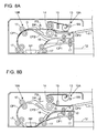
- the document transport controller 120 controls the document sheet feeder 10A to perform the sheet feed operation and controls the document transport portion 10B to perform the document transport operation. Specifically, as illustrated in FIG. 7A , the document sheet feeder 10A swings the pickup roller 13 downward to contact with the document D and moves the document stopper 15 upward to open the document transport path. In this state, the document sheet feeder 10A rotates the pickup roller 13 and the sheet feed roller pair 14 so as to feed the document D set on the document setting tray 11 to the main transport path CP1.
- the document transport portion 10B rotates the transport roller pair 17 so as to transport the document D fed to the main transport path CP1 along the main transport path CP1. In this way, because the document D is transported to the read position RP and passes the read position RP, one side of the document D (the side facing upward when being set on the document setting tray 11) is read in the read position RP.
- the document transport portion 10B swings the switching claw 18 so that the document transport path between the main transport path CP1 and the reversing transport path CP2 is opened before the front end of the document D reaches the branch point of the main transport path CP1 and the reversing transport path CP2. In this way, as illustrated in FIG. 7B , the document D after passing the read position RP is sent to the reversing transport path CP2.
- the document transport portion 10B performs document reversing operation for turning over the document D. Specifically, the document transport portion 10B rotates the reverse roller pair 19 in the forward direction so as to send the document D to the discharge tray 12 side from the front end thereof. Further, when the rear end of the document D enters the reversing transport path CP2, the document transport portion 10B rotates the reverse roller pair 19 in the reverse direction before the rear end of the document D passes by the reverse roller pair 19, so as to reverse the front and rear of the document D in the document transport direction. In this case, the document transport portion 10B swings the switching claw 18 so that the document transport path between the main transport path CP1 and the reversing transport path CP2 is blocked.
- the document D whose front and rear is reversed in the document transport direction is transported along the reversing transport path CP2 and returns to a position on the upstream side in the document transport direction of the read position RP in the main transport path CP1. Then, the document D after returning from the reversing transport path CP2 to the main transport path CP1 is turned over.
- the document transport portion 10B transports the turned-over document D (whose front and rear in the document transport direction is reversed) along the main transport path CP1. In this way, the document D is transport to the read position RP and passes the read position RP again. In this case, because the document D is turned over, the other side (unread side) of the document D is read in the read position RP.
- the document transport portion 10B swing the switching claw 18 so that the document transport path between the main transport path CP1 and the reversing transport path CP2 is opened before the front end of the document D whose both sides have been read reaches the branch point of the main transport path CP1 and the reversing transport path CP2. Therefore, as illustrated in FIG. 7D , the document D after passing the read position RP (the document D whose both sides have been read) is sent to the reversing transport path CP2. After this, the document transport portion 10B performs the document reversing operation again.
- the document D whose front and rear ends in the document transport direction are reversed again returns to a position on the upstream side in the document transport direction of the read position RP in the main transport path CP1.
- the document transport portion 10B transports the document D that is again turned over (document D whose both sides have been read) along the main transport path CP1 and discharges the document D to the document discharge tray 12.
- the document transport portion 10B swings the switching claw 18 so that the document transport path between the main transport path CP1 and the reversing transport path CP2 is blocked. Note that also for the second and subsequent sheets of the document D, both sides are read similarly to the first sheet of the document D, and the sheet is turned over again and then is discharged onto the document discharge tray 12.
- the operations illustrated in FIGS. 7D and 7E are omitted, and the operation illustrated in FIG. 7F is performed.
- the document transport path between the main transport path CP1 and the reversing transport path CP2 is blocked by the switching claw 18 so that the document D whose both sides have been read (the turned-over document D) is not sent to the reversing transport path CP2.
- the document D whose both sides have been read is not sent to the reversing transport path CP2 but is transported along the main transport path CP1 as it is, so as to be discharged onto the document discharge tray 12.
- the document D whose both sides have been read is not turned over and discharged onto the document discharge tray 12.
- both sides are read similarly to the first sheet of the document D, and the sheet is discharged onto the document discharge tray 12 without being turned over again.
- the document D discharged onto the document discharge tray 12 is turned over again. Therefore, one side of the document D (facing upward when the document is set) is caused to face the document discharge tray 12 side (to face downward). In this state, the sheets of the document D are stacked on the document discharge tray 12 in order from the first read sheet (uppermost sheet when the document D is set). In this way, pages of the plurality of sheets of the document D stacked on the document discharge tray 12 are sorted in order.
- this embodiment is configured to accept an instruction to select one of the first sheet discharging mode and the second sheet discharging mode for discharging the document D.
- the first sheet discharging mode can be selected in order to sort pages of the plurality of sheets of the document D discharged and stacked on the document discharge tray 12 to be in order
- the second sheet discharging mode can be selected in order to promptly finish the double-sided reading job.
- the document D when only one sheet of the document D is set on the document setting tray 11, the document D is discharged in the second sheet discharging mode regardless of the selected sheet discharging mode out of the first sheet discharging mode and the second sheet discharging mode.
- FIGS. 8A to 8D discharging operation of the document D when only one sheet of the document D is set on the document setting tray 11 is described.
- the document transport controller 120 controls the document sheet feeder 10A to perform the sheet feed operation and controls the document transport portion 10B to perform the document transport operation.
- the document sheet feeder 10A feeds the document D set on the document setting tray 11 to the main transport path CP1.
- the document transport portion 10B transports the document D fed to the main transport path CP1 to the read position RP. In this way, when the document D passes the read position RP, one side of the document D is read in the read position RP.
- the document transport portion 10B swings the switching claw 18 so that the document transport path between the main transport path CP1 and the reversing transport path CP2 is opened before the front end of the document D reaches the branch point of the main transport path CP1 and the reversing transport path CP2. In this way, as illustrated in FIG, 8B , the document D after passing the read position RP is sent to the reversing transport path CP2.
- the document transport controller 120 detects whether or not the document D exists at the document setting tray 11 based on an output of the document set sensor SS. In other words, when the first sheet of the document D is fed to the main transport path CP1, presence or absence of the document D on the document setting tray 11 is detected. In this case, when there is no document D at the document setting tray 11, it means that only one sheet of the document D was set on the document setting tray 11 (only the sheet of the document D that is currently being transported).
- the document transport controller 120 sets so that the document D is discharged in the second sheet discharging mode regardless of the selected sheet discharging mode out of the first sheet discharging mode and the second sheet discharging mode.
- the document transport portion 10B performs the document reversing operation and transports the turned-over document D along the main transport path CP1. In this way, the document D is transported to the read position RP and passes the read position RP again. In this case, because the document D is turned over, the other side (unread side) of the document D is read in the read position RP.
- the document transport portion 10B maintains the switching claw 18 to block the document transport path between the main transport path CP1 and the reversing transport path CP2. In this way, as illustrated in FIG, 8D , the document D whose both sides have been read is not sent to the reversing transport path CP2 but is transported along the main transport path CP1 as it is, so as to be discharged onto the document discharge tray 12.
- the document transport portion 10B discharges the document D onto the document discharge tray 12 without turning over again the document D whose both sides have been read (discharges the document D in the second sheet discharging mode).
- one of the first sheet discharging mode and the second sheet discharging mode is selected when the flowchart of FIG. 9 starts. Further, when the instruction to execute the double-sided reading job is accepted in a state where one or more sheets of document D are set on the document setting tray 11, the flowchart of FIG. 9 starts.
- Step S1 the document transport controller 120 controls the document sheet feeder 10A to start the sheet feed operation. In addition, the document transport controller 120 controls the document transport portion 10B to start the document transport operation. Then, in Step S2, the document transport controller 120 determines whether or not the rear end of the document D has passed the detection position DP (whether or not the first sheet of the document D has been fed to the main transport path CP1) based on the output of the document transport sensor FS. As a result, when the rear end of the document D has passed the detection position DP, the process proceeds to Step S3. When the rear end of the document D has not yet passed the detection position DP, the determination of Step S2 is repeated.
- Step S3 the document transport controller 120 determines whether or not there is the document D on the document setting tray 11 based on the output of the document set sensor SS. As a result, when there is the document D on the document setting tray 11, the process proceeds to Step S4. Note that when there is the document D on the document setting tray 11 at this time point, it means that a plurality of sheets of the document D was set on the document setting tray 11.
- Step S4 the document transport controller 120 sets so that the document D is discharged in the selected sheet discharging mode out of the first sheet discharging mode and the second sheet discharging mode.
- Step S3 when there is no document D on the document setting tray 11 in Step S3, the process proceeds to Step S5. Note that when there is no document D on the document setting tray 11 at this time point, it means that only one sheet of the document D was set on the document setting tray 11.
- Step S5 the document transport controller 120 sets so that the document D is discharged in the second sheet discharging mode.
- the image forming apparatus 100 (image reading device 200) of this embodiment includes the document setting tray 11 on which the document D is set, the image reader 20 configured to read the document D in the read position RP, the document discharge tray 12 onto which the document D after reading is discharged, the main transport path CP1 from the document setting tray 11 via the read position RP to the document discharge tray 12, the reversing transport path CP2 that branches from the main transport path CP1 on a downstream side of the read position RP and joins the main transport path CP1 on an upstream side of the read position RP of the main transport path CP1, the document transport controller 120 for controlling to transport the document D along the main transport path CP1, and controlling to transport the document D whose one side has been read in the read position RP along the reversing transport path CP2 so as to turn over the document D and to transport the turned-over document D to the read position RP when performing the double-sided reading job, and the operation panel 8 (operation portion) configured to accept the setting instruction concerning the double-sided reading job.
- the document transport controller 120 controls to discharge the document D in one of the two sheet discharging modes including the first sheet discharging mode in which the document D is turned over again after both sides of the document D have been read in the read position RP and then is discharged onto the document discharge tray 12, and the second sheet discharging mode in which the document D is discharged onto the document discharge tray 12 without being turned over again.
- the operation panel 8 accepts the instruction to select one of the first sheet discharging mode and the second sheet discharging mode to discharge the document D.
- the user when performing the double-sided reading job, the user can select a desired sheet discharging mode from the first sheet discharging mode and the second sheet discharging mode.
- a desired sheet discharging mode from the first sheet discharging mode and the second sheet discharging mode.
- the image reading device 200 and the image forming apparatus 100 including the image reading device 200 in which the double-sided reading job can be executed for alternately reading both sides of the document D in the single read position RP by turning over the document D, and hence usability for the user who performs the double-sided reading job can be improved.
- the document transport controller 120 detects that there is no document D on the document setting tray 11
- the document D is discharged in the second sheet discharging mode regardless of the selected sheet discharging mode out of the first sheet discharging mode and the second sheet discharging mode.
- the document D is discharged automatically in the second sheet discharging mode.
- the operation panel 8 accepts whether or not to discharge the document D in the first sheet discharging mode regardless of the number of sheets of the document D set on the document setting tray 11 when the first sheet discharging mode is selected. For instance, when the software key K1 is touched on the acceptance screen SS1 (see FIG. 6 ), the operation panel 8 displays an acceptance screen SS2 as illustrated in FIG. 10 and accepts whether or not to discharge the document D in the first sheet discharging mode regardless of the number of sheets of the document D set on the document setting tray 11.
- a software key K12 indicating "NO" is touched on the acceptance screen SS2 illustrated in FIG. 10 , it is set so that the sheet discharging mode is switched in accordance with the number of sheets of the document D set on the document setting tray 11. Specifically, when a bunch of document (a plurality of stacked sheets of the document D) is set on the document setting tray 11, the document D is discharged in the first sheet discharging mode. When only one sheet of the document D is set on the document setting tray 11, the document D is discharged in the second sheet discharging mode.
- the operation panel 8 accepts the number of sheets of the document D to be discharged in the second sheet discharging mode when the second sheet discharging mode is selected. For instance, when the software key K2 is touched on the acceptance screen SS1 (see FIG. 6 ), the operation panel 8 displays an acceptance screen SS3 as illustrated in FIG. 11 and accepts the number of sheets of the document D to be discharged in the second sheet discharging mode.
- the number of sheets of the document D corresponding to the numeric value are discharged in the second sheet discharging mode. For instance, when a numeric value "5" is input in the input box C, the first to fifth sheets of the document D are discharged in the second sheet discharging mode. In this case, when six or more sheets of document D are set on the document setting tray 11, the first to fifth sheets of the document D are discharged in the second sheet discharging mode, but the sixth and subsequent sheets of the document D are discharged in the first sheet discharging mode.
- the document transport portion 10B discharges the sheets of the document D corresponding to the numeric value accepted by the operation panel 8 in the second sheet discharging mode, and then discharges remaining sheets of the document D in the first sheet discharging mode when there are remaining sheets of the document D on the document setting tray 11.
- the number of sheets of the document D to be discharged in the second sheet discharging mode can be set to an arbitrary number, and hence usability for the user is good.
Description
- The present disclosure relates to an image reading device and an image forming apparatus including the same.
- Conventionally, there is known an image reading device capable of performing double-sided reading job in which both sides of a document can be read alternately in a single read position by turning over the document.
- When this image reading device capable of performing the double-sided reading job receives an instruction to perform the double-sided reading job, it first transports the document set on a document setting tray to a read position, and hence one side of the document (facing upward when the document is set) is read in the read position. After this, the document whose one side has been read is turned over, and the turned-over document (document whose one side is read) is transported back to a position on an upstream side of the read position in the document transport direction. Then, the turned-over document (document whose one side is read) is transported to the read position again. In this case, because the document has been turned over, the opposite side to the one side of the document can be read in the read position. Then, after reading both sides of the document, the document whose both sides have been read is discharged onto a document discharge tray.
- For instance, when a plurality of sheets of the document are set on the document setting tray and an instruction to perform the double-sided reading job is issued, the plurality of sheets of the document are transported one by one to be read sequentially. In this case, when the turned-over sheet of the document (whose both sides are read) is discharged as it is onto the document discharge tray, the one side of the sheet of the document (the side facing upward when the document is set) faces upward (in the same manner as when the document is set), and in this state the sheets of the document are stacked on the document discharge tray in order from the first read sheet of the document (uppermost sheet of the document when the document is set). Therefore, pages of the plurality of sheets of the document stacked on the document discharge tray are not in order. Therefore, when the user wants to sort the plurality of sheets of the document discharged onto the document discharge tray in correct order, the user must manually sort the plurality of sheets of the document though it is tiresome, and usability is not good.
- Therefore, it may be considered to configure to turn over the sheet of the document again after reading both sides before discharging the sheet of the document onto the document discharge tray. However, with this structure, because the additional operation of turning over the sheet of the document is necessary, time from start to finish of the double-sided reading job is increased. Therefore, usability is degraded for user who wants to promptly finish the double-sided reading job.
- Document
JP-A-2001 350 298 JP-A-2001 350 298 - An image reading device according to a first aspect of the present disclosure is defined in
claim 1. - An image forming apparatus according to a second aspect of the present disclosure includes the image reading device described above.
-
-
FIG. 1 is a schematic diagram of an image forming apparatus (image reading device) according to an embodiment of the present disclosure. -
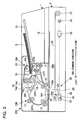
FIG. 2 is a detail diagram of the image reading device illustrated inFIG. 1 . -
FIG. 3 is a detail diagram of the image reading device illustrated inFIG. 1 . -
FIG. 4 is a block diagram for explaining a hardware structure of the image forming apparatus (image reading device) illustrated inFIG. 1 . -
FIG. 5 is a block diagram for explaining a hardware structure of the image reading device illustrated inFIG. 1 . -
FIG. 6 is a diagram of an acceptance screen displayed when accepting an instruction to select a sheet discharging mode in the image reading device illustrated inFIG. 1 . -
FIG. 7A is a diagram for explaining an operation of transporting the document when a plurality of sheets of the document are set on the document setting tray in the image reading device illustrated inFIG. 1 . -
FIG. 7B is a diagram for explaining the operation of transporting the document when a plurality of sheets of the document are set on the document setting tray in the image reading device illustrated inFIG. 1 . -
FIG. 7C is a diagram for explaining the operation of transporting the document when a plurality of sheets of the document are set on the document setting tray in the image reading device illustrated inFIG. 1 . -
FIG. 7D is a diagram for explaining the operation of transporting the document when a plurality of sheets of the document are set on the document setting tray in the image reading device illustrated inFIG. 1 . -
FIG. 7E is a diagram for explaining the operation of transporting the document when a plurality of sheets of the document are set on the document setting tray in the image reading device illustrated inFIG. 1 . -
FIG. 7F is a diagram for explaining the operation of transporting the document when a plurality of sheets of the document are set on the document setting tray in the image reading device illustrated inFIG. 1 . -
FIG. 8A is a diagram for explaining the operation of transporting the document when only one sheet of the document is set on the document setting tray in the image reading device illustrated inFIG. 1 . -
FIG. 8B is a diagram for explaining the operation of transporting the document when only one sheet of the document is set on the document setting tray in the image reading device illustrated inFIG. 1 . -
FIG. 8C is a diagram for explaining the operation of transporting the document when only one sheet of the document is set on the document setting tray in the image reading device illustrated inFIG. 1 . -
FIG. 8D is a diagram for explaining the operation of transporting the document when only one sheet of the document is set on the document setting tray in the image reading device illustrated inFIG. 1 . -
FIG. 9 is a flowchart for explaining a control flow when setting the sheet discharging mode in the image reading device illustrated inFIG. 1 . -
FIG. 10 is a diagram of an acceptance screen displayed when accepting detail setting of the sheet discharging mode in the image reading device illustrated inFIG. 1 . -
FIG. 11 is a diagram of the acceptance screen displayed when accepting the detail setting of the sheet discharging mode in the image reading device illustrated inFIG. 1 . - An image forming apparatus including an image reading device of this embodiment is described with an example of a multifunction peripheral having a plurality of functions including a scan function, a print function, a copy function, and the like.
- As illustrated in
FIG. 1 , animage forming apparatus 100 includes animage reading device 200 attached to an upper part of a main body. Note that a structure of theimage reading device 200 is described later in detail. - In addition, the
image forming apparatus 100 is equipped with anengine portion 7 including apaper sheet feeder 3, asheet transporting portion 4, animage forming portion 5 and a fixing portion 6. Further, theengine portion 7 prints an image based on image data (for example, image data obtained by reading a document D by the image reading device 200) on a paper sheet P and outputs the paper sheet P. - The
paper sheet feeder 3 includes a pickup roller 32 and a sheet feed roller pair 33, so as to feed the paper sheet P housed in acassette 31 to a sheet transport path CP. Thesheet transporting portion 4, which includes a plurality oftransport roller pairs 42, transports the paper sheet P along the sheet transport path CP, and discharges the paper sheet P after printing to adischarge tray 41. - The
image forming portion 5 includes aphotoreceptor drum 51, acharging device 52, anexposing device 53, a developingdevice 54, atransfer roller 55, and acleaning roller 56. Further, theimage forming portion 5 forms a toner image based on the image data and transfers the toner image onto the paper sheet P. The fixing portion 6 includes aheating roller 61 and apressing roller 62, so as to heat and press the toner image transferred onto the paper sheet P so that the toner image is fixed. - In addition, as illustrated in
FIG. 2 , theimage reading device 200 includes acontact glass 20a for transport reading and acontact glass 20b for place reading. Further, theimage reading device 200 is configured to be capable of executing the transport reading in which the document D transported onto thecontact glass 20a is read, and the place reading in which the document D placed on thecontact glass 20b is read. Specifically, theimage reading device 200 includes adocument transport unit 1 for transporting the document D and animage reading unit 2 for reading the document D. Note that in the following description, the read position (on thecontact glass 20a) in the transport reading is referred to as a read position RP. - The
document transport unit 1 includes adocument setting tray 11 on which the document D is set and adocument discharge tray 12 to which the read document D is discharged. In addition, thedocument transport unit 1 has a main transport path CP1 as a document transport path for transporting the document D to the read position RP. - The main transport path CP1 extends from the
document setting tray 11 via the read position RP to thedocument discharge tray 12. Thus, when the document D is transported from thedocument setting tray 11 to the main transport path CP1 and is transported along the main transport path CP1, the document D transported along the main transport path CP1 passes the read position RP. Then, one side of the document D (the side facing upward when the document D is set on the document setting tray 11) faces thecontact glass 20a so that the one side of the document D is read in the read position RP. Then, in a single-sided reading job in which only one side of the document D is read, the document D whose one side has been read in the read position RP is then transported along the main transport path CP1 and is discharged onto thedocument discharge tray 12. - The
document transport unit 1 also includes a reversing transport path CP2 as a document transport path for reversing front and rear of the document D in the document transport direction (for turning over the document D). This reversing transport path CP2 branches from the main transport path CP1 on a downstream side in the document transport direction of the read position RP and joins the main transport path CP1 on an upstream side in the document transport direction of the read position RP. Further, in the double-sided reading job for reading both the one side and the other side (opposite to the one side) of the document D, the document D whose one side has been read in the read position RP is not discharged to thedocument discharge tray 12 but is sent from the main transport path CP1 to the reversing transport path CP2. - The document D sent to the reversing transport path CP2 (document D whose one side has been read) is reversed in its front and rear in the document transport direction, and is returned to a position on the upstream side in the document transport direction of the read position RP in the main transport path CP1. Thus, the document D is turned over. The document D returned from the reversing transport path CP2 to the main transport path CP1 is transported along the main transport path CP1 so as to pass the read position RP again. In this case, because the document D is turned over, the other side of the document D (unread side) faces the
contact glass 20a. Therefore, the other side of the document D is read in the read position RP. In this way, in the double-sided reading job, the document D is turned over so that both sides of the document D are alternately read in the single read position RP. - In addition, the
document transport unit 1 includes adocument sheet feeder 10A for transporting the document D from thedocument setting tray 11 to the main transport path CP1. Thedocument sheet feeder 10A is disposed on the upstream side in the document transport direction of the main transport path CP1, and draws out the document D set in thedocument setting tray 11 so as to feed the document D to the main transport path CP1. Specifically, thedocument sheet feeder 10A includes apickup roller 13, a sheet feed roller pair 14 (adrive roller 14a and aseparation roller 14b), adocument stopper 15, and the like. - The
pickup roller 13 is attached in a swingable manner about a rotation axis of thedrive roller 14a of the sheetfeed roller pair 14, and stands by at an above position before starting document feeding (seeFIG. 2 ). Further, when starting document feeding, thepickup roller 13 swings down so as to press the document D set on the document setting tray 11 (seeFIG. 3 ). Thus, when thepickup roller 13 rotates, the document D set on thedocument setting tray 11 is drawn out. In addition, when thedocument setting tray 11 becomes empty after starting document feeding, thepickup roller 13 swings upward so as to return to the state before starting document feeding. - The sheet
feed roller pair 14 is constituted of thedrive roller 14a and theseparation roller 14b, which are disposed to be opposed to each other. Drive force is transmitted from a motor (not shown) to thedrive roller 14a so that thedrive roller 14a rotates. Theseparation roller 14b rotates to follow rotation of thedrive roller 14a. Then, the sheetfeed roller pair 14 is disposed on the downstream side in the document transport direction of thepickup roller 13. In this way, when the document D is drawn out from thedocument setting tray 11, the document D enters a document feed nip of the sheet feed roller pair 14 (between thedrive roller 14a and theseparation roller 14b) and is transported in a rotation direction of the sheetfeed roller pair 14 so as to be fed to the main transport path CP1. - Note that a torque limiter (not shown) is connected to the
separation roller 14b. In this way, when one sheet of the document D enters the document feed nip, theseparation roller 14b rotates following the document D fed in the document transport direction. On the other hand, when a plurality of sheets of the document D are overlapped and enter the document feed nip, theseparation roller 14b does not rotate to follow. Therefore, only the uppermost sheet of the document D contacting with thedrive roller 14a is fed in the document transport direction. In other words, occurrence of multiple feed is suppressed. In addition, in order to securely suppress the occurrence of multiple feed, afriction pad 16 is also disposed between thepickup roller 13 and the sheet feed roller pair 14 (just before the document feed nip). - The
document stopper 15 is attached between thepickup roller 13 and the sheetfeed roller pair 14 in a movable manner in an up and down direction. Before starting document feeding, thedocument stopper 15 is in a lower position so as to block the document transport path (seeFIG. 2 ). In this case, front ends of sheets of the document D set on thedocument setting tray 11 abut thedocument stopper 15. In other words, the front ends of sheets of the document D are aligned by thedocument stopper 15. Then, when starting document feeding, thedocument stopper 15 moves upward so as to open the document transport path between thepickup roller 13 and the sheet feed roller pair 14 (seeFIG. 3 ). In addition, when thedocument setting tray 11 becomes empty after starting document feeding, thedocument stopper 15 moves downward so as to return to the state before starting document feeding. - In addition, the
document transport unit 1 is equipped with adocument transport portion 10B. Thedocument transport portion 10B transports the document D fed to the main transport path CP1 to the read position RP. Further, when performing double-sided reading job, thedocument transport portion 10B sends the document D whose one side has been read in the read position RP from the main transport path CP1 to the reversing transport path CP2 so that the document D returns to a position on the upstream side in the document transport direction of the read position RP in the main transport path CP1 and is transported to the read position RP again (transports the turned-over document D to the read position RP). Thisdocument transport portion 10B includes atransport roller pair 17, a switchingclaw 18, and areverse roller pair 19. - A plurality of the transport roller pairs 17 are disposed along the main transport path CP1. Further, when the document D is fed to the main transport path CP1, the transport roller pairs 17 transport the document D along the main transport path CP1. Thus, the document D fed to the main transport path CP1 passes the read position RP.
- The switching
claw 18 is attached in a swingable manner at a branch point of the main transport path CP1 and the reversing transport path CP2 on the downstream side in the document transport direction of the read position RP. Further, when the document D after passing the read position RP is discharged onto thedocument discharge tray 12, the switchingclaw 18 swings to block the document transport path between the main transport path CP1 and the reversing transport path CP2 (seeFIG. 2 ). In this way, the document D after passing the read position RP (document D transported by the transport roller pair 17) is not sent to the reversing transport path CP2 but is transported along the main transport path CP1 as it is so as to be discharged onto thedocument discharge tray 12. - In addition, when the document D after passing the read position RP is sent to the reversing transport path CP2, the switching
claw 18 swings to open the document transport path between the main transport path CP1 and the reversing transport path CP2 (seeFIG. 3 ). In this way, the document D after passing the read position RP (document D transported by the transport roller pair 17) is sent to the reversing transport path CP2 and is not discharged onto thedocument discharge tray 12. - The
reverse roller pair 19 is a roller pair for reversing front and rear in the document transport direction of the document D sent to the reversing transport path CP2 and can be switched between forward and reverse directions of rotation. When the document D is sent to the reversing transport path CP2, thereverse roller pair 19 rotates in a forward direction so as to send the document D to thedischarge tray 12 side from the front end thereof. Further, when the rear end of the document D enters the reversing transport path CP2, thereverse roller pair 19 rotates in a reverse direction before the rear end of the document D passes by. Then, the switchingclaw 18 swings to block the document transport path between the main transport path CP1 and the reversing transport path CP2. In this way, the document D sent to the reversing transport path CP2 is transported along the reversing transport path CP2 in the state where the front and rear thereof in the document transport direction is reversed, and is returned to a position on the upstream side in the document transport direction of the read position RP in the main transport path CP1. Further, when the document D is returned from the reversing transport path CP2 to the main transport path CP1, the document D is turned over. - In addition, the
document transport unit 1 includes a document set sensor SS for detecting presence or absence of the document D on thedocument setting tray 11. The document set sensor SS is a reflective optical sensor including a light emitting portion and a light receiving portion. As to this document set sensor SS, when there is the document D on thedocument setting tray 11, light from the light emitting portion is reflected by the document D, and the light receiving portion receives the light reflected by the document D. On the other hand, when there is no document D on thedocument setting tray 11, the light from the light emitting portion is not reflected by the document D so that the light receiving portion cannot receive light. In this way, the document set sensor SS changes the output between the case where there is the document D on thedocument setting tray 11 and the case where there is no document D on thedocument setting tray 11. Alternatively, it is possible to use an optical sensor with an actuator as the document set sensor SS, in which an optical path between the light emitting portion and the light receiving portion is blocked (or opened) when there is the document D on thedocument setting tray 11, while the optical path between the light emitting portion and the light receiving portion is opened (or blocked) when there is no document D on thedocument setting tray 11. - Further, the
document transport unit 1 includes a plurality of document transport sensors FS for detecting presence or absence of the document D (arrival and pass of the document D) at a plurality of positions in the document transport path (the main transport path CP1 and the reversing transport path CP2). The plurality of document transport sensors FS are optical sensors, each of which changes the output based on whether or not there is the document D at a corresponding detection position. For instance, one of the plurality of document transport sensors FS is used for detecting presence or absence of the document D at a position between the sheetfeed roller pair 14 and thetransport roller pair 17 closest to the sheet feed roller pair 14 (hereinafter referred to as a detection position DP). Note thatFIG. 2 illustrates only the document transport sensor FS for detecting presence or absence of the document D at the detection position DP in order to facilitate viewing the diagram. - The
image reading unit 2 is equipped with animage reader 20 including alamp 21, mirrors 22, alens 23, animage sensor 24, and the like. - The
lamp 21 includes a plurality of LED elements generating light for irradiating the document D. The plurality of LED element are linearly arranged in main scanning direction as a reading line direction (perpendicular to a paper plane ofFIG. 2 ) though it is not shown. Note that a cold cathode fluorescent lamp or the like may be used as thelamp 21. Further, when reading the document D transported onto thecontact glass 20a, thelamp 21 emits light to thecontact glass 20a (light after passing through thecontact glass 20a irradiates the document D). On the other hand, when reading the document D placed on thecontact glass 20b, thelamp 21 emits light to thecontact glass 20b (light after passing through thecontact glass 20b irradiates the document D). Reflection light reflected by the document D is reflected by themirrors 22 and is led to thelens 23. Thelens 23 focuses the reflection light. - The
image sensor 24 receives the reflection light reflected by the document D (light focused by the lens 23) so as to read the document D by line unit. Thisimage sensor 24 is constituted of a CCD including a plurality of photoelectric conversion elements arranged linearly in the main scanning direction. When receiving the reflection light, theimage sensor 24 performs photoelectric conversion for each pixel by line unit so as to accumulate charge. Then, theimage sensor 24 outputs an analog signal corresponding to the accumulated charge. In other words, an analog output of each pixel of theimage sensor 24 varies in accordance with amount of the reflection light. - In addition, the
lamp 21 and themirrors 22 are held by a movingframe 25 capable of moving in sub scanning direction perpendicular to the main scanning direction. The movingframe 25 is connected to an end of awire 26. The other end of thewire 26 is connected to a windingdrum 27 that rotates to wind thewire 26. In this way, when the windingdrum 27 rotates, the movingframe 25 moves in the sub scanning direction so that thelamp 21 and themirrors 22 moves together with the movingframe 25 in the sub scanning direction. Note that a plurality of thewires 26 are connected to the movingframe 25 so that the plurality ofwires 26 are stretched. - When reading the document D transported onto the
contact glass 20a, the movingframe 25 moves to a position below thecontact glass 20a. After that, thedocument transport unit 1 transports the document D onto thecontact glass 20a. Then, thelamp 21 emits light to the document D passing on thecontact glass 20a, and theimage sensor 24 continuously repeats photoelectric conversion of the reflection light reflected by the document D. In this way, the document D is read by line unit. - On the other hand, when reading the document D placed on the
contact glass 20b, the movingframe 25 moves in the sub scanning direction (from left to right viewed from the front). Then, during the period while the movingframe 25 is moving in the sub scanning direction, thelamp 21 emits light to the document D placed on thecontact glass 20b, and theimage sensor 24 continuously repeats photoelectric conversion of the reflection light reflected by the document D. In this way, the document D is read by line unit. - In addition, with reference to
FIG. 1 again, the image forming apparatus 100 (image reading device 200) is equipped with anoperation panel 8. Theoperation panel 8 includes anLCD display portion 81 with a touch panel. ThisLCD display portion 81 displays software keys for accepting various settings and the like made by a user and messages. Further, theoperation panel 8 also includes hardware keys such as a ten-key 82 and astart key 83. - As illustrated in
FIG. 4 , the image forming apparatus 100 (image reading device 200) includes amain controller 110. Themain controller 110 includes amain CPU 111, animage processor 112, and astorage portion 113. Theimage processor 112 is constituted of an ASIC dedicated for image processing, or the like. Theimage processor 112 performs image processing (enlargement/reduction, density conversion, data format conversion, and the like) on the image data. Thestorage portion 113 is constituted of a ROM, a RAM, and the like, so as to store programs and data. Further, themain controller 110 performs general control of theimage forming apparatus 100 based on the program and the data stored in thestorage portion 113. - In addition, as illustrated in
FIG. 5 , the image forming apparatus 100 (image reading device 200) includes adocument transport controller 120 and animage read controller 130. Thedocument transport controller 120 includes aCPU 121 and astorage portion 122. Thedocument transport controller 120 receives an instruction from themain controller 110 so as to control sheet feed operation by thedocument sheet feeder 10A and document transport operation by thedocument transport portion 10B. The image readcontroller 130 includes aCPU 131 and astorage portion 132. The image readcontroller 130 receives an instruction from themain controller 110 so as to control an image read operation by theimage reader 20. - The
document transport controller 120 is connected to the document set sensor SS and detects presence or absence of the document D on thedocument setting tray 11 based on the document set sensor SS. In this structure, the document setting tray SS connected to thedocument transport controller 120 corresponds to a "document set detector" of the present disclosure. - Further, the
document transport controller 120 is connected to the plurality of document transport sensors FS and detects presence or absence of the document D at the plurality of positions in the document transport path (the main transport path CP1 and the reversing transport path CP2) based on outputs of the plurality of document transport sensors FS. For instance, thedocument transport controller 120 detects presence or absence of the document D at the detection position DP so as to measure sheet feed timing or to count the number of fed sheets. - The image read
controller 130 is connected to ananalog processor 201, acorrection portion 202, and animage memory 203, so as to process an output of the image reader 20 (analog output of the image sensor 24). Theanalog processor 201 includes an amplifier circuit, an A/D conversion circuit, and the like. Further, theanalog processor 201 amplifies the analog output of theimage sensor 24 and converts into digital image data so as to outputs the result. Thecorrection portion 202 performs correction such as shading correction. Theimage memory 203 accumulates image data and transmits them to the main controller 110 (image processor 112). - In addition, the
main controller 110 is connected to theoperation panel 8 so as to control display operation of theoperation panel 8 and to detect an operation performed by the user with theoperation panel 8. For instance, when the user presses thestart key 83, theoperation panel 8 accepts the pressing operation as an instruction to execute the reading job (single-sided reading job or double-sided reading job). Then, when theoperation panel 8 accepts the executing instruction of the reading job, themain controller 110 instructs individual portions of thedocument transport controller 120 and the image readcontroller 130 so as to control thedocument transport unit 1 and theimage reading unit 2 to execute the reading job. - The
operation panel 8 also accepts setting about the reading job. For instance, theoperation panel 8 accepts setting of the sheet discharging mode for discharging the document D after reading the both sides. In this structure, theoperation panel 8 corresponds to the "operation portion" of the present disclosure. Note that the sheet discharging mode will be described later. - When performing the double-sided reading job, after both sides of the document D have been read in the read position RP, the
image reading device 200 discharges the document D to thedocument discharge tray 12 in one of the first sheet discharging mode and the second sheet discharging mode. In the first sheet discharging mode, after reading both sides of the document D in the read position RP, the document D is turned over again and then is discharged to thedocument discharge tray 12. In the second sheet discharging mode, after reading both sides of the document D in the read position RP, the document D is discharged to thedocument discharge tray 12 without being turned over again. - The
operation panel 8 accepts an instruction to select one of the first sheet discharging mode and the second sheet discharging mode for discharging the document D. For instance, when accepting the instruction to select the sheet discharging mode, theoperation panel 8 displays an acceptance screen SS1 as illustrated inFIG. 6 . Note that a touch operation of a software key K1 indicating "YES" on the acceptance screen SS1 is the operation for selecting the first sheet discharging mode, and a touch operation of a software key K2 indicating "NO" is the operation for selecting the second sheet discharging mode. - Hereinafter, with reference to
FIGS. 7A to 7F , an operation of discharging the document D in the first sheet discharging mode is specifically described. Note that in the following description, it is supposed that a bunch of the document (a plurality of stacked sheets of the document D) is set on thedocument setting tray 11. - First, when accepting an instruction to perform the double-sided reading job, the
document transport controller 120 controls thedocument sheet feeder 10A to perform the sheet feed operation and controls thedocument transport portion 10B to perform the document transport operation. Specifically, as illustrated inFIG. 7A , thedocument sheet feeder 10A swings thepickup roller 13 downward to contact with the document D and moves thedocument stopper 15 upward to open the document transport path. In this state, thedocument sheet feeder 10A rotates thepickup roller 13 and the sheetfeed roller pair 14 so as to feed the document D set on thedocument setting tray 11 to the main transport path CP1. - The
document transport portion 10B rotates thetransport roller pair 17 so as to transport the document D fed to the main transport path CP1 along the main transport path CP1. In this way, because the document D is transported to the read position RP and passes the read position RP, one side of the document D (the side facing upward when being set on the document setting tray 11) is read in the read position RP. - In addition, the
document transport portion 10B swings the switchingclaw 18 so that the document transport path between the main transport path CP1 and the reversing transport path CP2 is opened before the front end of the document D reaches the branch point of the main transport path CP1 and the reversing transport path CP2. In this way, as illustrated inFIG. 7B , the document D after passing the read position RP is sent to the reversing transport path CP2. - After that, the
document transport portion 10B performs document reversing operation for turning over the document D. Specifically, thedocument transport portion 10B rotates thereverse roller pair 19 in the forward direction so as to send the document D to thedischarge tray 12 side from the front end thereof. Further, when the rear end of the document D enters the reversing transport path CP2, thedocument transport portion 10B rotates thereverse roller pair 19 in the reverse direction before the rear end of the document D passes by thereverse roller pair 19, so as to reverse the front and rear of the document D in the document transport direction. In this case, thedocument transport portion 10B swings the switchingclaw 18 so that the document transport path between the main transport path CP1 and the reversing transport path CP2 is blocked. In this way, the document D whose front and rear is reversed in the document transport direction is transported along the reversing transport path CP2 and returns to a position on the upstream side in the document transport direction of the read position RP in the main transport path CP1. Then, the document D after returning from the reversing transport path CP2 to the main transport path CP1 is turned over. - Next, as illustrated in
FIG. 7C , thedocument transport portion 10B transports the turned-over document D (whose front and rear in the document transport direction is reversed) along the main transport path CP1. In this way, the document D is transport to the read position RP and passes the read position RP again. In this case, because the document D is turned over, the other side (unread side) of the document D is read in the read position RP. - In addition, the
document transport portion 10B swing the switchingclaw 18 so that the document transport path between the main transport path CP1 and the reversing transport path CP2 is opened before the front end of the document D whose both sides have been read reaches the branch point of the main transport path CP1 and the reversing transport path CP2. Therefore, as illustrated inFIG. 7D , the document D after passing the read position RP (the document D whose both sides have been read) is sent to the reversing transport path CP2. After this, thedocument transport portion 10B performs the document reversing operation again. In this way, as illustrated inFIG, 7E , the document D whose front and rear ends in the document transport direction are reversed again (the document D whose both sides have been read) returns to a position on the upstream side in the document transport direction of the read position RP in the main transport path CP1. - Further, as illustrated in
FIG, 7F , thedocument transport portion 10B transports the document D that is again turned over (document D whose both sides have been read) along the main transport path CP1 and discharges the document D to thedocument discharge tray 12. In other words, in this case, thedocument transport portion 10B swings the switchingclaw 18 so that the document transport path between the main transport path CP1 and the reversing transport path CP2 is blocked. Note that also for the second and subsequent sheets of the document D, both sides are read similarly to the first sheet of the document D, and the sheet is turned over again and then is discharged onto thedocument discharge tray 12. - Next, an operation of discharging the document D in the second sheet discharging mode is described. Note that in the following description, it is supposed that a bunch of the document (a plurality of stacked sheets of the document D) is set on the
document setting tray 11. - First, when an instruction to execute the double-sided reading job is accepted, an operation similar to that illustrated in
FIGS. 7A to 7C is performed. In other words, the document D is turned over so that both sides of the document D are alternately read in a single read position RP. - Here, in the second sheet discharging mode, unlike the first sheet discharging mode, the operations illustrated in
FIGS. 7D and7E are omitted, and the operation illustrated inFIG. 7F is performed. Specifically, the document transport path between the main transport path CP1 and the reversing transport path CP2 is blocked by the switchingclaw 18 so that the document D whose both sides have been read (the turned-over document D) is not sent to the reversing transport path CP2. In this way, the document D whose both sides have been read is not sent to the reversing transport path CP2 but is transported along the main transport path CP1 as it is, so as to be discharged onto thedocument discharge tray 12. In other words, the document D whose both sides have been read is not turned over and discharged onto thedocument discharge tray 12. Note that also for the second and subsequent sheets of the document D, both sides are read similarly to the first sheet of the document D, and the sheet is discharged onto thedocument discharge tray 12 without being turned over again. - In this way, in the first sheet discharging mode, the document D discharged onto the
document discharge tray 12 is turned over again. Therefore, one side of the document D (facing upward when the document is set) is caused to face thedocument discharge tray 12 side (to face downward). In this state, the sheets of the document D are stacked on thedocument discharge tray 12 in order from the first read sheet (uppermost sheet when the document D is set). In this way, pages of the plurality of sheets of the document D stacked on thedocument discharge tray 12 are sorted in order. For instance, it is supposed that two sheets of the document D are set on thedocument setting tray 11, one side of the first sheet of the document D that is the uppermost side when the document is set is the first page, the other side of the first sheet is the second page, one side of the second sheet of the document D is the third page, and the other side of the second sheet is the fourth page. In this case, when the two sheets of the document D are turned over again and are stacked in order on thedischarge tray 12, the one side of the first sheet of the document D (the first page) faces downward, and the one side of the second sheet of the document D (the third page) also faces downward. Therefore, pages of the two sheets of the document D are sorted in order. However, in the first sheet discharging mode, because the sheets of the document D are turned over again, time from start to end of the double-sided reading job is elongated. - On the other hand, in the second sheet discharging mode, sheets of the document D are not turned over again before being discharged onto the
document discharge tray 12. Therefore, the time from start to end of the double-sided reading job is shortened because the sheets of the document D are not turned over. However, in the second sheet discharging mode, the one side of the sheet of the document D (facing upward when the document is set) faces upward (the same direction as when the document is set). In this state, the sheets of the document D are stacked in order from the first read sheet (the uppermost sheet when the document is set) on thedocument discharge tray 12. Therefore, pages of the plurality of sheets of the document D stacked on thedocument discharge tray 12 are not sorted in order. - Therefore, this embodiment is configured to accept an instruction to select one of the first sheet discharging mode and the second sheet discharging mode for discharging the document D. In this way, the first sheet discharging mode can be selected in order to sort pages of the plurality of sheets of the document D discharged and stacked on the
document discharge tray 12 to be in order, while the second sheet discharging mode can be selected in order to promptly finish the double-sided reading job. - However, in this embodiment, when only one sheet of the document D is set on the
document setting tray 11, the document D is discharged in the second sheet discharging mode regardless of the selected sheet discharging mode out of the first sheet discharging mode and the second sheet discharging mode. Hereinafter, with reference toFIGS. 8A to 8D , discharging operation of the document D when only one sheet of the document D is set on thedocument setting tray 11 is described. - First, when the instruction to execute the double-sided reading job is accepted, the
document transport controller 120 controls thedocument sheet feeder 10A to perform the sheet feed operation and controls thedocument transport portion 10B to perform the document transport operation. In other words, as illustrated inFIG, 8A , thedocument sheet feeder 10A feeds the document D set on thedocument setting tray 11 to the main transport path CP1. Further, thedocument transport portion 10B transports the document D fed to the main transport path CP1 to the read position RP. In this way, when the document D passes the read position RP, one side of the document D is read in the read position RP. - In addition, the
document transport portion 10B swings the switchingclaw 18 so that the document transport path between the main transport path CP1 and the reversing transport path CP2 is opened before the front end of the document D reaches the branch point of the main transport path CP1 and the reversing transport path CP2. In this way, as illustrated inFIG, 8B , the document D after passing the read position RP is sent to the reversing transport path CP2. - Here, when detecting that the rear end of the document D passes the detection position DP (detecting that the rear end of the document D is released from the
document sheet feeder 10A) based on an output of the document transport sensor FS, thedocument transport controller 120 detects whether or not the document D exists at thedocument setting tray 11 based on an output of the document set sensor SS. In other words, when the first sheet of the document D is fed to the main transport path CP1, presence or absence of the document D on thedocument setting tray 11 is detected. In this case, when there is no document D at thedocument setting tray 11, it means that only one sheet of the document D was set on the document setting tray 11 (only the sheet of the document D that is currently being transported). Therefore, when it is detected that there is no document D at thedocument setting tray 11, thedocument transport controller 120 sets so that the document D is discharged in the second sheet discharging mode regardless of the selected sheet discharging mode out of the first sheet discharging mode and the second sheet discharging mode. - After that, as illustrated in
FIG, 8C , thedocument transport portion 10B performs the document reversing operation and transports the turned-over document D along the main transport path CP1. In this way, the document D is transported to the read position RP and passes the read position RP again. In this case, because the document D is turned over, the other side (unread side) of the document D is read in the read position RP. - In addition, because it is set to discharge the document D in the second sheet discharging mode in this case, the
document transport portion 10B maintains the switchingclaw 18 to block the document transport path between the main transport path CP1 and the reversing transport path CP2. In this way, as illustrated inFIG, 8D , the document D whose both sides have been read is not sent to the reversing transport path CP2 but is transported along the main transport path CP1 as it is, so as to be discharged onto thedocument discharge tray 12. In other words, regardless of the selected sheet discharging mode out of the first sheet discharging mode and the second sheet discharging mode, thedocument transport portion 10B discharges the document D onto thedocument discharge tray 12 without turning over again the document D whose both sides have been read (discharges the document D in the second sheet discharging mode). - Hereinafter, with reference to the flowchart illustrated in
FIG. 9 , a control flow when the sheet discharging mode is set is described. - It is supposed that one of the first sheet discharging mode and the second sheet discharging mode is selected when the flowchart of
FIG. 9 starts. Further, when the instruction to execute the double-sided reading job is accepted in a state where one or more sheets of document D are set on thedocument setting tray 11, the flowchart ofFIG. 9 starts. - In Step S1, the
document transport controller 120 controls thedocument sheet feeder 10A to start the sheet feed operation. In addition, thedocument transport controller 120 controls thedocument transport portion 10B to start the document transport operation. Then, in Step S2, thedocument transport controller 120 determines whether or not the rear end of the document D has passed the detection position DP (whether or not the first sheet of the document D has been fed to the main transport path CP1) based on the output of the document transport sensor FS. As a result, when the rear end of the document D has passed the detection position DP, the process proceeds to Step S3. When the rear end of the document D has not yet passed the detection position DP, the determination of Step S2 is repeated. - When the process proceeds to Step S3, the
document transport controller 120 determines whether or not there is the document D on thedocument setting tray 11 based on the output of the document set sensor SS. As a result, when there is the document D on thedocument setting tray 11, the process proceeds to Step S4. Note that when there is the document D on thedocument setting tray 11 at this time point, it means that a plurality of sheets of the document D was set on thedocument setting tray 11. - When the process proceeds to Step S4, the
document transport controller 120 sets so that the document D is discharged in the selected sheet discharging mode out of the first sheet discharging mode and the second sheet discharging mode. - On the other hand, when there is no document D on the
document setting tray 11 in Step S3, the process proceeds to Step S5. Note that when there is no document D on thedocument setting tray 11 at this time point, it means that only one sheet of the document D was set on thedocument setting tray 11. - When the process proceeds to Step S5, the
document transport controller 120 sets so that the document D is discharged in the second sheet discharging mode. - The image forming apparatus 100 (image reading device 200) of this embodiment includes the
document setting tray 11 on which the document D is set, theimage reader 20 configured to read the document D in the read position RP, thedocument discharge tray 12 onto which the document D after reading is discharged, the main transport path CP1 from thedocument setting tray 11 via the read position RP to thedocument discharge tray 12, the reversing transport path CP2 that branches from the main transport path CP1 on a downstream side of the read position RP and joins the main transport path CP1 on an upstream side of the read position RP of the main transport path CP1, thedocument transport controller 120 for controlling to transport the document D along the main transport path CP1, and controlling to transport the document D whose one side has been read in the read position RP along the reversing transport path CP2 so as to turn over the document D and to transport the turned-over document D to the read position RP when performing the double-sided reading job, and the operation panel 8 (operation portion) configured to accept the setting instruction concerning the double-sided reading job. Further, thedocument transport controller 120 controls to discharge the document D in one of the two sheet discharging modes including the first sheet discharging mode in which the document D is turned over again after both sides of the document D have been read in the read position RP and then is discharged onto thedocument discharge tray 12, and the second sheet discharging mode in which the document D is discharged onto thedocument discharge tray 12 without being turned over again. Theoperation panel 8 accepts the instruction to select one of the first sheet discharging mode and the second sheet discharging mode to discharge the document D. - In this embodiment, when performing the double-sided reading job, the user can select a desired sheet discharging mode from the first sheet discharging mode and the second sheet discharging mode. In other words, when it is desired to sort pages of the plurality of sheets of the document D discharged onto the
document discharge tray 12, it is possible to turn over the sheets of the document D again before the document D are discharged onto thedocument discharge tray 12. Further, when it is desired to promptly finish the double-sided reading job, it is possible to discharge the document D onto thedocument discharge tray 12 without turning over the document D again (to omit the operation to turn over the document D). Therefore, it is possible to improve usability for both the user who wants to sort pages of the plurality of sheets of the document D discharged onto thedocument discharge tray 12 and the user who wants to promptly finish the double-sided reading job. - For instance, when the plurality of sheets of the document D are read to generate electronic data to be stored, and the plurality of sheets of the document D after reading are discarded, it is not necessary that pages of the plurality of sheets of the document D discharged onto the
document discharge tray 12 are sorted in order. In this case, when it is set that the document D is discharged only in the first sheet discharging mode, the operation of turning over the document D is executed despite the operation is not necessary, which is burdensome for the user. However, when the second sheet discharging mode is selectable as the sheet discharging mode, the unnecessary operation (of turning over the document D) can be omitted so that the double-sided reading job is promptly finished, and hence usability for the user is improved. - In this way, in this embodiment, it is possible to provide the
image reading device 200 and theimage forming apparatus 100 including theimage reading device 200, in which the double-sided reading job can be executed for alternately reading both sides of the document D in the single read position RP by turning over the document D, and hence usability for the user who performs the double-sided reading job can be improved. - In addition, in this embodiment, as described above, when the first sheet of the document D is fed to the main transport path CP1, and when the document transport controller 120 (document set detector) detects that there is no document D on the
document setting tray 11, the document D is discharged in the second sheet discharging mode regardless of the selected sheet discharging mode out of the first sheet discharging mode and the second sheet discharging mode. In other words, when only one sheet of the document D was set on thedocument setting tray 11, the document D is discharged automatically in the second sheet discharging mode. Here, when only one sheet of the document D was set on thedocument setting tray 11, even if the sheet of the document D is discharged onto thedocument discharge tray 12 without being turned over again, usability for the user is not degraded. Therefore, when only one sheet of the document D was set on thedocument setting tray 11, it is preferred to promptly finish the double-sided reading job by discharging the document D in the second sheet discharging mode. - Note that in the structure described above, it is possible to configure that the
operation panel 8 accepts whether or not to discharge the document D in the first sheet discharging mode regardless of the number of sheets of the document D set on thedocument setting tray 11 when the first sheet discharging mode is selected. For instance, when the software key K1 is touched on the acceptance screen SS1 (seeFIG. 6 ), theoperation panel 8 displays an acceptance screen SS2 as illustrated inFIG. 10 and accepts whether or not to discharge the document D in the first sheet discharging mode regardless of the number of sheets of the document D set on thedocument setting tray 11. - When a software key K11 indicating "YES" is touched on the acceptance screen SS2 illustrated in
FIG. 10 , it is set so that the document D is discharged in the first sheet discharging mode regardless of the number of sheets of the document D set on thedocument setting tray 11. In this case, even if thedocument transport controller 120 detects that there is no document D on the document setting tray 11 (even if only one sheet of the document D was set on the document setting tray 11) when feeding of the first sheet of the document D to the main transport path CP1 is completed, thedocument transport controller 120 controls to discharge the document D not in the second sheet discharging mode but in the first sheet discharging mode. - On the other hand, when a software key K12 indicating "NO" is touched on the acceptance screen SS2 illustrated in
FIG. 10 , it is set so that the sheet discharging mode is switched in accordance with the number of sheets of the document D set on thedocument setting tray 11. Specifically, when a bunch of document (a plurality of stacked sheets of the document D) is set on thedocument setting tray 11, the document D is discharged in the first sheet discharging mode. When only one sheet of the document D is set on thedocument setting tray 11, the document D is discharged in the second sheet discharging mode. - With this structure, even if only one sheet of the document D is set on the setting
tray 11, the document D can be discharged in the first sheet discharging mode, and hence usability for the user is good. - In addition, in the structure described above, it is possible to configure that the
operation panel 8 accepts the number of sheets of the document D to be discharged in the second sheet discharging mode when the second sheet discharging mode is selected. For instance, when the software key K2 is touched on the acceptance screen SS1 (seeFIG. 6 ), theoperation panel 8 displays an acceptance screen SS3 as illustrated inFIG. 11 and accepts the number of sheets of the document D to be discharged in the second sheet discharging mode. - When a numeric value is input in an input box C on the acceptance screen SS3 illustrated in
FIG. 11 , the number of sheets of the document D corresponding to the numeric value are discharged in the second sheet discharging mode. For instance, when a numeric value "5" is input in the input box C, the first to fifth sheets of the document D are discharged in the second sheet discharging mode. In this case, when six or more sheets of document D are set on thedocument setting tray 11, the first to fifth sheets of the document D are discharged in the second sheet discharging mode, but the sixth and subsequent sheets of the document D are discharged in the first sheet discharging mode. In other words, thedocument transport portion 10B discharges the sheets of the document D corresponding to the numeric value accepted by theoperation panel 8 in the second sheet discharging mode, and then discharges remaining sheets of the document D in the first sheet discharging mode when there are remaining sheets of the document D on thedocument setting tray 11. - With this structure, the number of sheets of the document D to be discharged in the second sheet discharging mode can be set to an arbitrary number, and hence usability for the user is good.
- The above embodiments of the invention as well as the appended claims and figures show multiple characterizing features of the invention in specific combinations. The skilled person will easily be able to consider further combinations or sub-combinations of these features in order to adapt the invention as defined in the claims to his specific needs.
Claims (5)
- An image reading device (200) capable of performing double-sided reading job which reads both sides of a document (D) alternately at a single read position (RP) by turning over the document (D), comprising:a document setting tray (11) on which the document (D) is set;an image reader (20) configured to read the document (D) in the read position (RP);a document discharge tray (12) onto which the document (D) after reading is discharged;a main transport path (CP1) from the document setting tray (11) via the read position (RP) to the document discharge tray (12);the reversing transport path (CP2) branching from the main transport path (CP1) on a downstream side of the read position (RP) and joining the main transport path (CP1) on an upstream side of the read position (RP) of the main transport path (CP1);a document transport controller (120) for controlling to transport the document (D) along the main transport path (CP1), and controlling to transport the document (D) whose one side has been read in the read position (RP) along the reversing transport path (CP2) so as to turn over the document (D) and to transport the turned-over document (D) to the read position (RP) when performing the double-sided reading job; andan operation portion (8) configured to accept a setting instruction concerning the double-sided reading job, whereinthe document transport controller (120) controls to discharge the document (D) in one of two sheet discharging modes including a first sheet discharging mode in which the document (D) is turned over again after both sides of the document (D) have been read in the read position (RP) and then is discharged onto the document discharge tray (12), and a second sheet discharging mode in which the document (D) is discharged onto the document discharge tray (12) without being turned over again,the operation portion (8) accepts an instruction to select one of the first sheet discharging mode and the second sheet discharging mode to discharge the document (D), and when the second sheet discharging mode is selected, the operation portion (8) accepts the number of sheets of the document (D) to be discharged in the second sheet discharging mode among the sheets of the document (D) set on the document setting tray (11), and the document transport controller (120) controls to discharge the sheets of the document (D) corresponding to the number of sheets accepted by the operation portion (8) in the second sheet discharging mode.
- The image reading device (200) according to claim 1, further comprising a document set detector (SS) which detects presence or absence of the document (D) on the document setting tray (11), wherein
when the document set detector (SS) detects that there is no document (D) when feeding of a first sheet of the document (D) to the main transport path (CP1) is completed, the document transport controller (120) controls to discharge the document (D) in the second sheet discharging mode regardless of the selected sheet discharging mode out of the first sheet discharging mode and the second sheet discharging mode. - The image reading device (200) according to claim 1 or 2, further comprising a document set detector (SS) for detecting presence or absence of the document (D) on the document setting tray (11), wherein
when the first sheet discharging mode is selected, the operation portion (8) can accept the first sheet discharging mode regardless of the number of sheets of the document (D) set on the document setting tray (11), and
when the operation portion (8) accepts the first sheet discharging mode, the document transport controller (120) discharges the document (D) in the first sheet discharging mode even if the document set detector (120) detects there is no document (D) when feeding of the first sheet of the document (D) to the main transport path (CP1) is finished. - The image reading device (200) according to any one of claim 1 to 3, wherein the document transport controller (120) discharges the sheets of the document (D) corresponding to the number of sheets accepted by the operation portion (8) in the second sheet discharging mode, and then discharges remaining sheets of the document (D) in the first sheet discharging mode when there are remaining sheets of the document (D) on the document setting tray (11).
- An image forming apparatus (100) comprising the image reading device (200) according to any one of claims 1 to 4.
Applications Claiming Priority (1)
| Application Number | Priority Date | Filing Date | Title |
|---|---|---|---|
| JP2013109733A JP5881642B2 (en) | 2013-05-24 | 2013-05-24 | Image reading apparatus and image forming apparatus having the same |
Publications (2)
| Publication Number | Publication Date |
|---|---|
| EP2806624A1 EP2806624A1 (en) | 2014-11-26 |
| EP2806624B1 true EP2806624B1 (en) | 2015-12-23 |
Family
ID=50972433
Family Applications (1)
| Application Number | Title | Priority Date | Filing Date |
|---|---|---|---|
| EP14169197.2A Not-in-force EP2806624B1 (en) | 2013-05-24 | 2014-05-21 | Image reading device and image forming apparatus including the same |
Country Status (4)
| Country | Link |
|---|---|
| US (1) | US8994964B2 (en) |
| EP (1) | EP2806624B1 (en) |
| JP (1) | JP5881642B2 (en) |
| CN (1) | CN104184917B (en) |
Families Citing this family (3)
| Publication number | Priority date | Publication date | Assignee | Title |
|---|---|---|---|---|
| JP6361620B2 (en) * | 2015-09-28 | 2018-07-25 | 京セラドキュメントソリューションズ株式会社 | Reading apparatus and image forming apparatus provided with the same |
| KR20170056452A (en) * | 2015-11-13 | 2017-05-23 | 스미또모 가가꾸 가부시키가이샤 | Porous layer for nonaqueous electrolyte secondary battery separator, and nonaqueous electrolyte secondary battery laminated separator |
| JP7456505B2 (en) | 2020-07-21 | 2024-03-27 | 京セラドキュメントソリューションズ株式会社 | Image reading device |
Family Cites Families (11)
| Publication number | Priority date | Publication date | Assignee | Title |
|---|---|---|---|---|
| US5883660A (en) * | 1991-06-22 | 1999-03-16 | Minolta Camera Kabushiki Kaishi | Digital copier for two-sided reading using various writing modes |
| US5430536A (en) * | 1993-10-12 | 1995-07-04 | Xerox Corporation | Automatic duplex and simplex document handler for electronic input |
| US5634187A (en) * | 1996-02-29 | 1997-05-27 | Xerox Corporation | Automatic simplex and duplex copying system |
| JP3889188B2 (en) * | 1998-09-11 | 2007-03-07 | 株式会社リコー | Automatic document feeder |
| JP4296459B2 (en) * | 2000-06-08 | 2009-07-15 | 村田機械株式会社 | Double-sided document reader |
| KR100739793B1 (en) * | 2006-02-06 | 2007-07-13 | 삼성전자주식회사 | Image reading apparatus including a automatic document feeder |
| JP4450052B2 (en) * | 2007-11-13 | 2010-04-14 | コニカミノルタビジネステクノロジーズ株式会社 | Double-sided image reading apparatus and image forming apparatus |
| JP4745405B2 (en) | 2009-01-26 | 2011-08-10 | シャープ株式会社 | Printing device |
| JP2010183144A (en) * | 2009-02-03 | 2010-08-19 | Kyocera Mita Corp | Automatic original feeding device and image reader |
| JP5634139B2 (en) * | 2010-06-22 | 2014-12-03 | キヤノン株式会社 | Image reading method and image reading apparatus |
| JP2012222448A (en) * | 2011-04-05 | 2012-11-12 | Canon Inc | Image reading device, control method therefor, and program |
-
2013
- 2013-05-24 JP JP2013109733A patent/JP5881642B2/en active Active
-
2014
- 2014-05-20 US US14/283,128 patent/US8994964B2/en not_active Expired - Fee Related
- 2014-05-21 EP EP14169197.2A patent/EP2806624B1/en not_active Not-in-force
- 2014-05-21 CN CN201410215876.8A patent/CN104184917B/en not_active Expired - Fee Related
Also Published As
| Publication number | Publication date |
|---|---|
| JP5881642B2 (en) | 2016-03-09 |
| US20140347683A1 (en) | 2014-11-27 |
| CN104184917A (en) | 2014-12-03 |
| US8994964B2 (en) | 2015-03-31 |
| JP2014230189A (en) | 2014-12-08 |
| CN104184917B (en) | 2017-11-24 |
| EP2806624A1 (en) | 2014-11-26 |
Similar Documents
| Publication | Publication Date | Title |
|---|---|---|
| US8882107B2 (en) | Sheet conveyance device, document feeder, image forming apparatus, and multi feed detection method | |
| US8400690B2 (en) | Apparatus and method for detecting and compensating for multi-fed document scanning errors | |
| JP6904699B2 (en) | Image reader, image reading method | |
| JP5874203B2 (en) | Sheet transport device | |
| US9866708B2 (en) | Original reading apparatus, method for controlling the same, and storage medium | |
| JP5984309B2 (en) | Sheet conveying apparatus, document conveying apparatus, and image forming apparatus | |
| US11388306B2 (en) | Image reading apparatus | |
| JP7229723B2 (en) | IMAGE PROCESSING DEVICE, CONTROL METHOD THEREOF, AND PROGRAM | |
| EP2806624B1 (en) | Image reading device and image forming apparatus including the same | |
| JP2007228184A (en) | Original reading device and image forming device | |
| JP4687350B2 (en) | Document transport device, image reading device | |
| EP2667257B1 (en) | Display input device and image forming apparatus | |
| JP4990732B2 (en) | Image reading apparatus and image forming apparatus | |
| JP5383296B2 (en) | Image reading apparatus and method, and program | |
| JP2021103817A (en) | Image forming apparatus | |
| JP4853681B2 (en) | Image processing device | |
| JP2011102853A (en) | Automatic document feeding apparatus, image reading apparatus, and image forming apparatus | |
| JP6941216B2 (en) | Image reader and its control method | |
| US11218610B2 (en) | Reading apparatus and multi feed detection method | |
| JP6028484B2 (en) | Image forming apparatus | |
| JP6055739B2 (en) | Image reading apparatus and image forming apparatus | |
| US20160080596A1 (en) | Image-reading device, communication device, and image-forming device | |
| JP5935403B2 (en) | Automatic document conveying device, image reading device, image forming apparatus, document conveying method, and document conveying control program | |
| JP2004104187A (en) | Digital copying machine | |
| JP2007079391A (en) | Image forming apparatus, control method for image forming apparatus, and control program for image forming apparatus |
Legal Events
| Date | Code | Title | Description |
|---|---|---|---|
| PUAI | Public reference made under article 153(3) epc to a published international application that has entered the european phase |
Free format text: ORIGINAL CODE: 0009012 |
|
| 17P | Request for examination filed |
Effective date: 20140521 |
|
| AK | Designated contracting states |
Kind code of ref document: A1 Designated state(s): AL AT BE BG CH CY CZ DE DK EE ES FI FR GB GR HR HU IE IS IT LI LT LU LV MC MK MT NL NO PL PT RO RS SE SI SK SM TR |
|
| AX | Request for extension of the european patent |
Extension state: BA ME |
|
| GRAP | Despatch of communication of intention to grant a patent |
Free format text: ORIGINAL CODE: EPIDOSNIGR1 |
|
| R17P | Request for examination filed (corrected) |
Effective date: 20150526 |
|
| RBV | Designated contracting states (corrected) |
Designated state(s): AL AT BE BG CH CY CZ DE DK EE ES FI FR GB GR HR HU IE IS IT LI LT LU LV MC MK MT NL NO PL PT RO RS SE SI SK SM TR |
|
| INTG | Intention to grant announced |
Effective date: 20150626 |
|
| GRAS | Grant fee paid |
Free format text: ORIGINAL CODE: EPIDOSNIGR3 |
|
| GRAA | (expected) grant |
Free format text: ORIGINAL CODE: 0009210 |
|
| AK | Designated contracting states |
Kind code of ref document: B1 Designated state(s): AL AT BE BG CH CY CZ DE DK EE ES FI FR GB GR HR HU IE IS IT LI LT LU LV MC MK MT NL NO PL PT RO RS SE SI SK SM TR |
|
| REG | Reference to a national code |
Ref country code: GB Ref legal event code: FG4D |
|
| REG | Reference to a national code |
Ref country code: CH Ref legal event code: EP |
|
| REG | Reference to a national code |
Ref country code: IE Ref legal event code: FG4D |
|
| REG | Reference to a national code |
Ref country code: AT Ref legal event code: REF Ref document number: 766982 Country of ref document: AT Kind code of ref document: T Effective date: 20160115 |
|
| REG | Reference to a national code |
Ref country code: DE Ref legal event code: R096 Ref document number: 602014000600 Country of ref document: DE |
|
| REG | Reference to a national code |
Ref country code: FR Ref legal event code: PLFP Year of fee payment: 3 |
|
| REG | Reference to a national code |
Ref country code: LT Ref legal event code: MG4D |
|
| REG | Reference to a national code |
Ref country code: NL Ref legal event code: MP Effective date: 20151223 |
|
| PG25 | Lapsed in a contracting state [announced via postgrant information from national office to epo] |
Ref country code: LT Free format text: LAPSE BECAUSE OF FAILURE TO SUBMIT A TRANSLATION OF THE DESCRIPTION OR TO PAY THE FEE WITHIN THE PRESCRIBED TIME-LIMIT Effective date: 20151223 Ref country code: NO Free format text: LAPSE BECAUSE OF FAILURE TO SUBMIT A TRANSLATION OF THE DESCRIPTION OR TO PAY THE FEE WITHIN THE PRESCRIBED TIME-LIMIT Effective date: 20160323 Ref country code: HR Free format text: LAPSE BECAUSE OF FAILURE TO SUBMIT A TRANSLATION OF THE DESCRIPTION OR TO PAY THE FEE WITHIN THE PRESCRIBED TIME-LIMIT Effective date: 20151223 |
|
| REG | Reference to a national code |
Ref country code: AT Ref legal event code: MK05 Ref document number: 766982 Country of ref document: AT Kind code of ref document: T Effective date: 20151223 |
|
| PG25 | Lapsed in a contracting state [announced via postgrant information from national office to epo] |
Ref country code: FI Free format text: LAPSE BECAUSE OF FAILURE TO SUBMIT A TRANSLATION OF THE DESCRIPTION OR TO PAY THE FEE WITHIN THE PRESCRIBED TIME-LIMIT Effective date: 20151223 Ref country code: NL Free format text: LAPSE BECAUSE OF FAILURE TO SUBMIT A TRANSLATION OF THE DESCRIPTION OR TO PAY THE FEE WITHIN THE PRESCRIBED TIME-LIMIT Effective date: 20151223 Ref country code: GR Free format text: LAPSE BECAUSE OF FAILURE TO SUBMIT A TRANSLATION OF THE DESCRIPTION OR TO PAY THE FEE WITHIN THE PRESCRIBED TIME-LIMIT Effective date: 20160324 Ref country code: RS Free format text: LAPSE BECAUSE OF FAILURE TO SUBMIT A TRANSLATION OF THE DESCRIPTION OR TO PAY THE FEE WITHIN THE PRESCRIBED TIME-LIMIT Effective date: 20151223 Ref country code: SE Free format text: LAPSE BECAUSE OF FAILURE TO SUBMIT A TRANSLATION OF THE DESCRIPTION OR TO PAY THE FEE WITHIN THE PRESCRIBED TIME-LIMIT Effective date: 20151223 Ref country code: LV Free format text: LAPSE BECAUSE OF FAILURE TO SUBMIT A TRANSLATION OF THE DESCRIPTION OR TO PAY THE FEE WITHIN THE PRESCRIBED TIME-LIMIT Effective date: 20151223 |
|
| PG25 | Lapsed in a contracting state [announced via postgrant information from national office to epo] |
Ref country code: ES Free format text: LAPSE BECAUSE OF FAILURE TO SUBMIT A TRANSLATION OF THE DESCRIPTION OR TO PAY THE FEE WITHIN THE PRESCRIBED TIME-LIMIT Effective date: 20151223 Ref country code: IT Free format text: LAPSE BECAUSE OF FAILURE TO SUBMIT A TRANSLATION OF THE DESCRIPTION OR TO PAY THE FEE WITHIN THE PRESCRIBED TIME-LIMIT Effective date: 20151223 Ref country code: CZ Free format text: LAPSE BECAUSE OF FAILURE TO SUBMIT A TRANSLATION OF THE DESCRIPTION OR TO PAY THE FEE WITHIN THE PRESCRIBED TIME-LIMIT Effective date: 20151223 |
|
| PG25 | Lapsed in a contracting state [announced via postgrant information from national office to epo] |
Ref country code: RO Free format text: LAPSE BECAUSE OF FAILURE TO SUBMIT A TRANSLATION OF THE DESCRIPTION OR TO PAY THE FEE WITHIN THE PRESCRIBED TIME-LIMIT Effective date: 20151223 Ref country code: AT Free format text: LAPSE BECAUSE OF FAILURE TO SUBMIT A TRANSLATION OF THE DESCRIPTION OR TO PAY THE FEE WITHIN THE PRESCRIBED TIME-LIMIT Effective date: 20151223 Ref country code: PL Free format text: LAPSE BECAUSE OF FAILURE TO SUBMIT A TRANSLATION OF THE DESCRIPTION OR TO PAY THE FEE WITHIN THE PRESCRIBED TIME-LIMIT Effective date: 20151223 Ref country code: PT Free format text: LAPSE BECAUSE OF FAILURE TO SUBMIT A TRANSLATION OF THE DESCRIPTION OR TO PAY THE FEE WITHIN THE PRESCRIBED TIME-LIMIT Effective date: 20160426 Ref country code: EE Free format text: LAPSE BECAUSE OF FAILURE TO SUBMIT A TRANSLATION OF THE DESCRIPTION OR TO PAY THE FEE WITHIN THE PRESCRIBED TIME-LIMIT Effective date: 20151223 Ref country code: SK Free format text: LAPSE BECAUSE OF FAILURE TO SUBMIT A TRANSLATION OF THE DESCRIPTION OR TO PAY THE FEE WITHIN THE PRESCRIBED TIME-LIMIT Effective date: 20151223 Ref country code: SM Free format text: LAPSE BECAUSE OF FAILURE TO SUBMIT A TRANSLATION OF THE DESCRIPTION OR TO PAY THE FEE WITHIN THE PRESCRIBED TIME-LIMIT Effective date: 20151223 Ref country code: IS Free format text: LAPSE BECAUSE OF FAILURE TO SUBMIT A TRANSLATION OF THE DESCRIPTION OR TO PAY THE FEE WITHIN THE PRESCRIBED TIME-LIMIT Effective date: 20160423 Ref country code: BE Free format text: LAPSE BECAUSE OF NON-PAYMENT OF DUE FEES Effective date: 20160531 |
|
| REG | Reference to a national code |
Ref country code: DE Ref legal event code: R097 Ref document number: 602014000600 Country of ref document: DE |
|
| PLBE | No opposition filed within time limit |
Free format text: ORIGINAL CODE: 0009261 |
|
| STAA | Information on the status of an ep patent application or granted ep patent |
Free format text: STATUS: NO OPPOSITION FILED WITHIN TIME LIMIT |
|
| PG25 | Lapsed in a contracting state [announced via postgrant information from national office to epo] |
Ref country code: DK Free format text: LAPSE BECAUSE OF FAILURE TO SUBMIT A TRANSLATION OF THE DESCRIPTION OR TO PAY THE FEE WITHIN THE PRESCRIBED TIME-LIMIT Effective date: 20151223 |
|
| 26N | No opposition filed |
Effective date: 20160926 |
|
| PG25 | Lapsed in a contracting state [announced via postgrant information from national office to epo] |
Ref country code: BE Free format text: LAPSE BECAUSE OF FAILURE TO SUBMIT A TRANSLATION OF THE DESCRIPTION OR TO PAY THE FEE WITHIN THE PRESCRIBED TIME-LIMIT Effective date: 20151223 Ref country code: LU Free format text: LAPSE BECAUSE OF FAILURE TO SUBMIT A TRANSLATION OF THE DESCRIPTION OR TO PAY THE FEE WITHIN THE PRESCRIBED TIME-LIMIT Effective date: 20160521 |
|
| REG | Reference to a national code |
Ref country code: IE Ref legal event code: MM4A |
|
| PG25 | Lapsed in a contracting state [announced via postgrant information from national office to epo] |
Ref country code: SI Free format text: LAPSE BECAUSE OF FAILURE TO SUBMIT A TRANSLATION OF THE DESCRIPTION OR TO PAY THE FEE WITHIN THE PRESCRIBED TIME-LIMIT Effective date: 20151223 |
|
| REG | Reference to a national code |
Ref country code: FR Ref legal event code: PLFP Year of fee payment: 4 |
|
| PG25 | Lapsed in a contracting state [announced via postgrant information from national office to epo] |
Ref country code: IE Free format text: LAPSE BECAUSE OF NON-PAYMENT OF DUE FEES Effective date: 20160521 |
|
| REG | Reference to a national code |
Ref country code: CH Ref legal event code: PL |
|
| PG25 | Lapsed in a contracting state [announced via postgrant information from national office to epo] |
Ref country code: CH Free format text: LAPSE BECAUSE OF NON-PAYMENT OF DUE FEES Effective date: 20170531 Ref country code: LI Free format text: LAPSE BECAUSE OF NON-PAYMENT OF DUE FEES Effective date: 20170531 |
|
| REG | Reference to a national code |
Ref country code: FR Ref legal event code: PLFP Year of fee payment: 5 |
|
| PG25 | Lapsed in a contracting state [announced via postgrant information from national office to epo] |
Ref country code: HU Free format text: LAPSE BECAUSE OF FAILURE TO SUBMIT A TRANSLATION OF THE DESCRIPTION OR TO PAY THE FEE WITHIN THE PRESCRIBED TIME-LIMIT; INVALID AB INITIO Effective date: 20140521 |
|
| PG25 | Lapsed in a contracting state [announced via postgrant information from national office to epo] |
Ref country code: MC Free format text: LAPSE BECAUSE OF FAILURE TO SUBMIT A TRANSLATION OF THE DESCRIPTION OR TO PAY THE FEE WITHIN THE PRESCRIBED TIME-LIMIT Effective date: 20151223 Ref country code: CY Free format text: LAPSE BECAUSE OF FAILURE TO SUBMIT A TRANSLATION OF THE DESCRIPTION OR TO PAY THE FEE WITHIN THE PRESCRIBED TIME-LIMIT Effective date: 20151223 Ref country code: MT Free format text: LAPSE BECAUSE OF NON-PAYMENT OF DUE FEES Effective date: 20160531 Ref country code: MK Free format text: LAPSE BECAUSE OF FAILURE TO SUBMIT A TRANSLATION OF THE DESCRIPTION OR TO PAY THE FEE WITHIN THE PRESCRIBED TIME-LIMIT Effective date: 20151223 |
|
| PG25 | Lapsed in a contracting state [announced via postgrant information from national office to epo] |
Ref country code: BG Free format text: LAPSE BECAUSE OF FAILURE TO SUBMIT A TRANSLATION OF THE DESCRIPTION OR TO PAY THE FEE WITHIN THE PRESCRIBED TIME-LIMIT Effective date: 20151223 |
|
| PG25 | Lapsed in a contracting state [announced via postgrant information from national office to epo] |
Ref country code: TR Free format text: LAPSE BECAUSE OF FAILURE TO SUBMIT A TRANSLATION OF THE DESCRIPTION OR TO PAY THE FEE WITHIN THE PRESCRIBED TIME-LIMIT Effective date: 20151223 Ref country code: AL Free format text: LAPSE BECAUSE OF FAILURE TO SUBMIT A TRANSLATION OF THE DESCRIPTION OR TO PAY THE FEE WITHIN THE PRESCRIBED TIME-LIMIT Effective date: 20151223 |
|
| PGFP | Annual fee paid to national office [announced via postgrant information from national office to epo] |
Ref country code: DE Payment date: 20200506 Year of fee payment: 7 Ref country code: FR Payment date: 20200414 Year of fee payment: 7 |
|
| PGFP | Annual fee paid to national office [announced via postgrant information from national office to epo] |
Ref country code: GB Payment date: 20200513 Year of fee payment: 7 |
|
| REG | Reference to a national code |
Ref country code: DE Ref legal event code: R119 Ref document number: 602014000600 Country of ref document: DE |
|
| GBPC | Gb: european patent ceased through non-payment of renewal fee |
Effective date: 20210521 |
|
| PG25 | Lapsed in a contracting state [announced via postgrant information from national office to epo] |
Ref country code: GB Free format text: LAPSE BECAUSE OF NON-PAYMENT OF DUE FEES Effective date: 20210521 Ref country code: DE Free format text: LAPSE BECAUSE OF NON-PAYMENT OF DUE FEES Effective date: 20211201 |
|
| PG25 | Lapsed in a contracting state [announced via postgrant information from national office to epo] |
Ref country code: FR Free format text: LAPSE BECAUSE OF NON-PAYMENT OF DUE FEES Effective date: 20210531 |