EP2806594A1 - Method and device for evaluating the stability of a telecommunication line - Google Patents
Method and device for evaluating the stability of a telecommunication line Download PDFInfo
- Publication number
- EP2806594A1 EP2806594A1 EP13305678.8A EP13305678A EP2806594A1 EP 2806594 A1 EP2806594 A1 EP 2806594A1 EP 13305678 A EP13305678 A EP 13305678A EP 2806594 A1 EP2806594 A1 EP 2806594A1
- Authority
- EP
- European Patent Office
- Prior art keywords
- line
- stability
- quality information
- physical
- service quality
- Prior art date
- Legal status (The legal status is an assumption and is not a legal conclusion. Google has not performed a legal analysis and makes no representation as to the accuracy of the status listed.)
- Granted
Links
Images


Classifications
-
- H—ELECTRICITY
- H04—ELECTRIC COMMUNICATION TECHNIQUE
- H04L—TRANSMISSION OF DIGITAL INFORMATION, e.g. TELEGRAPHIC COMMUNICATION
- H04L1/00—Arrangements for detecting or preventing errors in the information received
- H04L1/20—Arrangements for detecting or preventing errors in the information received using signal quality detector
-
- H—ELECTRICITY
- H04—ELECTRIC COMMUNICATION TECHNIQUE
- H04L—TRANSMISSION OF DIGITAL INFORMATION, e.g. TELEGRAPHIC COMMUNICATION
- H04L1/00—Arrangements for detecting or preventing errors in the information received
- H04L1/24—Testing correct operation
-
- H—ELECTRICITY
- H04—ELECTRIC COMMUNICATION TECHNIQUE
- H04L—TRANSMISSION OF DIGITAL INFORMATION, e.g. TELEGRAPHIC COMMUNICATION
- H04L41/00—Arrangements for maintenance, administration or management of data switching networks, e.g. of packet switching networks
- H04L41/50—Network service management, e.g. ensuring proper service fulfilment according to agreements
- H04L41/5003—Managing SLA; Interaction between SLA and QoS
- H04L41/5009—Determining service level performance parameters or violations of service level contracts, e.g. violations of agreed response time or mean time between failures [MTBF]
- H04L41/5012—Determining service level performance parameters or violations of service level contracts, e.g. violations of agreed response time or mean time between failures [MTBF] determining service availability, e.g. which services are available at a certain point in time
- H04L41/5016—Determining service level performance parameters or violations of service level contracts, e.g. violations of agreed response time or mean time between failures [MTBF] determining service availability, e.g. which services are available at a certain point in time based on statistics of service availability, e.g. in percentage or over a given time
-
- H—ELECTRICITY
- H04—ELECTRIC COMMUNICATION TECHNIQUE
- H04L—TRANSMISSION OF DIGITAL INFORMATION, e.g. TELEGRAPHIC COMMUNICATION
- H04L41/00—Arrangements for maintenance, administration or management of data switching networks, e.g. of packet switching networks
- H04L41/50—Network service management, e.g. ensuring proper service fulfilment according to agreements
- H04L41/5061—Network service management, e.g. ensuring proper service fulfilment according to agreements characterised by the interaction between service providers and their network customers, e.g. customer relationship management
- H04L41/5067—Customer-centric QoS measurements
-
- H—ELECTRICITY
- H04—ELECTRIC COMMUNICATION TECHNIQUE
- H04M—TELEPHONIC COMMUNICATION
- H04M3/00—Automatic or semi-automatic exchanges
- H04M3/22—Arrangements for supervision, monitoring or testing
- H04M3/26—Arrangements for supervision, monitoring or testing with means for applying test signals or for measuring
- H04M3/28—Automatic routine testing ; Fault testing; Installation testing; Test methods, test equipment or test arrangements therefor
- H04M3/30—Automatic routine testing ; Fault testing; Installation testing; Test methods, test equipment or test arrangements therefor for subscriber's lines, for the local loop
- H04M3/305—Automatic routine testing ; Fault testing; Installation testing; Test methods, test equipment or test arrangements therefor for subscriber's lines, for the local loop testing of physical copper line parameters, e.g. capacitance or resistance
- H04M3/306—Automatic routine testing ; Fault testing; Installation testing; Test methods, test equipment or test arrangements therefor for subscriber's lines, for the local loop testing of physical copper line parameters, e.g. capacitance or resistance for frequencies above the voice frequency, e.g. xDSL line qualification
-
- H—ELECTRICITY
- H04—ELECTRIC COMMUNICATION TECHNIQUE
- H04L—TRANSMISSION OF DIGITAL INFORMATION, e.g. TELEGRAPHIC COMMUNICATION
- H04L41/00—Arrangements for maintenance, administration or management of data switching networks, e.g. of packet switching networks
- H04L41/50—Network service management, e.g. ensuring proper service fulfilment according to agreements
- H04L41/5003—Managing SLA; Interaction between SLA and QoS
- H04L41/5019—Ensuring fulfilment of SLA
- H04L41/5025—Ensuring fulfilment of SLA by proactively reacting to service quality change, e.g. by reconfiguration after service quality degradation or upgrade
Definitions
- the present invention refers to a method and device evaluating the stability of communication over a telecommunication line. Furthermore, the present invention refers to a monitoring station comprising such a device and a computer program product arranged for carrying out such a method.
- DLM digital subscriber lines
- ADSLx technology use frequencies up to about 1.1 MHz.
- VDSL2 technology can be applied with bandwidths up to 17 MHz or even 30 MHz.
- additional measures have been implemented in order to increase the bit rate of digital subscriber lines. As a consequence, digital subscriber lines have become more sensible to disturbances and impairments and more advanced solutions for dynamic line management are needed.
- dynamic line management monitors at least one parameter describing a physical characteristic of one or more digital subscriber lines and thereby dynamically accesses and monitors the stability of the line.
- a line is considered stable if transmission at a certain bit rate can be maintained during a sufficiently long time interval. Otherwise, the line is considered as unstable. Unstable lines typically have an unacceptable high rate of resynchronisations or an unacceptable high rate of coding violations or other transmission errors. If dynamic line management detects that a certain line is unstable, the maximum bit rate of that line may be reduced in order to stabilize that line.
- the quality of service e. g. the bit rate under the stability assumption
- dynamic line management should not operate too conservatively and classify a line as unstable although the user does not feel any practical impacts on the quality of service, because a stabilisation action would typically reduce the bit rate or the latency of the line.
- MTBE Mean Time Between Errors
- MTBR Mean Time Between Resynchronisations
- a disadvantage of the known dynamic line management approach based on empirical rules lies in the inaccuracy of the empirical rules. Using the inaccurate empirical rules leads to suboptimal dynamic line management decisions. In particular, a bit rate of a line could be reduced by a stabilisation action although the reduction of the bit rate is actually not needed. In other words, the empirical rules may lead to a too conservative dynamic line management in terms of stability resulting in a comparatively low bit rate on the digital subscriber lines. By contrast, trying to increase the overall bit rate by simply implementing less conservative but still inaccurate empirical rules could harm to the overall stability of the lines and therefore could lead to the DLM not be seen as working well anymore.
- the object of the present invention is to provide a method and device for evaluating and/or estimating the stability of communication over a telecommunication line that allows for assessing the stability of the line more accurately and being more in concordance with the end-user quality of experience, thereby improving the performance (e. g. bit rate or latency) of the line without degrading its stability.
- a method for evaluating the stability of communication over a telecommunication line comprising ascertaining physical line data characterizing a physical characteristic of each line of a fist set of subscriber lines; collecting service quality information describing a quality of a service provided over each line of a second set of subscriber lines; associating the service quality information related to at least one particular line with the physical line data related to the same particular line; and determining a decision criterion from the physical line data with associated service quality information, said decision criterion being determined for deciding to which stability class of a plurality of stability classes the digital subscriber line belongs.
- the first set and the second set of subscriber lines are identical.
- the first set and the second set differ from each other; preferably, the first and the second set have at least some lines in common, i.e. are not disjoint.
- Ascertaining the physical line data may comprise retrieving the physical line data from at least one network element where the physical line data are created. Typically this network element is a node that is directly connected to the subscriber line, such as an access node or a DSL modem. In some embodiments, the physical line data are collected from multiple network elements (e.g. multiple access nodes) of an access network.
- an accurate decision criterion based on a sound statistical analysis is established.
- the decision criterion being based on correlating the physical line data with the service quality information, is more accurate than the empirical rules known from the prior art. As a consequence, a less conservative dynamic line management approach can be used without the risk of stability problems.
- the service quality information describes the quality of the services (e.g. IP television, video on demand, Internet access, Voice over IP, etc) consumed by the individual users.
- the service quality information therefore refers to the service quality experienced by the users.
- the physical line data includes physical parameters that are determined by a node connected to the line (e.g. an access node like a DSLAM or customer side termination node like a DSL modem) by measurement or logging and/or counting of events related to transmission errors.
- the method comprises calculating at least one threshold for a stability metric of the line, the at least one threshold depending on the physical line data with associated service quality information.
- the at least one threshold constitutes the decision criterion.
- the at least one threshold can be compared with the stability metric in order to decide to which stability class the digital subscriber line belongs.
- the present invention is not limited to a threshold-based decision criterion.
- the method may generate decision rules that can be processed in order to find the stability class.
- the plurality of stability classes corresponds to three classes: a class of stable lines, a class of risky lines and a class of unstable lines.
- the plurality of classes consists of only two classes, e.g. the class of stable lines and the class of unstable lines.
- the method comprises calculating at least one pair of thresholds.
- the deciding to which stability class the line belongs may comprises comparing the stability metric with each threshold of the pair of thresholds.
- the method does not include said comparing but only generates the threshold to be used by a different method or device.
- the service quality information comprises an indication on whether or not the quality of service provided by the respective line is satisfactory. This information may be associated with the physical line data, e.g. by tagging the physical line data with the indication.
- the service quality information is based on customer feedback.
- the customer feedback may be retrieved from a call centre or contact centre that has asked the customers if they consider the quality of the services provided over their digital subscriber lines as satisfactory or not.
- any other suitable approach for collecting the service quality information may be applied, e.g. electronic customer feedback forms may be used.
- the stability metric depends on multiple physical characteristics of the line.
- the physical characteristics may include a number CV of coding violations within a certain time interval (e.g. one day), a number of errored seconds ES or several errored seconds SES within the time interval, a number Resync of resynchronizations of the two modem circuitries connected to opposite ends of a line within the time interval and/or a number of failed initialisations FI of the line within the time interval.
- the stability metric is a Mean Time Between Errors (MTBE) or a Mean Time Between Resynchronisations (MTBR)
- the method comprises adapting a calculation rule, e.g. an algorithm or an equation, for calculating the stability metric such that a discriminant measure related to the service quality information is optimized. Any type of discriminant measure may be applied.
- the discriminant measure characterizes an overlapping between a first distribution and a second distribution of the stability metric, with the first distribution being determined from pieces of the physical line data associated with service quality information indicating a satisfactory service quality and the second distribution being determined from pieces of the physical line data associated with service quality information indicating an unsatisfactory service quality.
- the calculation rule includes a linear combination of the multiple physical characteristics and said adapting the calculation rule includes computing weight coefficients of the linear combination.
- the method comprises calculating the at least one weight coefficient depending on the physical line data with associated quality information.
- the weight coefficients are calculated by optimizing (maximizing or minimizing) the discriminant measure.
- the weight coefficient may be determined by a discriminant analysis.
- a device for evaluating the stability of communication over a telecommunication line being operable, preferably arranged, for determining physical line data characterizing a physical characteristic of each line of a fist set of subscriber lines; collecting service quality information describing a quality of a service provided over each line of a second set of subscriber lines; associating the service quality information related to at least one particular line with the physical line data related to the same particular line; and determining a decision criterion from the physical line data with associated service quality information, said decision criterion being determined for deciding to which stability class of a plurality of stability classes the digital subscriber line belongs.
- a device is operable, preferably programmed, for executing a method for evaluating the stability of communication over a telecommunication line described herein.
- a monitoring station for evaluating the stability of communication over a telecommunication line comprising a device for evaluating the stability of communication over a telecommunication line described herein.
- a computer program product preferably a computer readable storage medium
- the computer program product comprising a computer program that is programmed for executing a method for evaluating the stability of communication over a telecommunication line described herein.
- the storage medium may include magnetic memory (e.g. hard disc drives or tapes), optical memory (e.g. optical discs) or semiconductor memory (e.g. Flash memory, ROM, RAM).
- the computer program product may be provided by a server for download over a communication network like the Internet.
- Figure 1 shows a communication network 11 comprising telecommunication lines 13, at least one telecommunication line 13 having a pair of electrical conductors.
- a first end 16 of the line 13 is connected to a network side termination node of the network 11, further referred to as access node 17, and a second end 18 of the line 13 is connected to a terminal side termination node 19 of the network 11.
- the terminal side termination node 19 may be part of customer premises equipment (CPE 21) of the network 11.
- CPE 21 customer premises equipment
- the telecommunication line 13 is a Digital Subscriber Line (DSL), such as VDSL2, ADSLx or the like. Consequently, the access node 17 may be a DSL Access Multiplexer (DSLAM) or another type of DSL access node.
- the terminal side termination node 19 may be a DSL modem or include a DSL modem.
- the access node 17 has first modem circuitry 23 to which the first end 16 of the lines 13 is connected.
- the access node 17 has a first controller 25 adapted for controlling the operation of the access node 17.
- the first controller 25 is a programmable computer comprising a processor 27, e. g. a microprocessor, and a storage element 29, e.g. semiconductor memory.
- the terminal side termination node 19 includes second modem circuitry 33 to which the second end 18 of the line 13 is connected. Furthermore, the terminal side termination node 19 comprises a second controller 31.
- the second controller 31 may have the same basic configuration as the first controller 25, i.e. the second controller 31 may be a programmable computer and comprise a processor 27 and/or a storage element 29.
- At least some lines 13 are part of a binder 35 and extend in parallel to each other.
- the binder 35 may comprise an electrically conductive, preferably metallic, shielding 38 that may be grounded as depicted in Figure 1 . Because at least some lines extend in parallel to each other in the binder 35, crosstalk between the lines 13 may occur.
- the network 11 may comprise an optional monitoring station 39 connected e. g. via an interconnection network 41 to at least one of the nodes 17, 19 such that the station 39 can communicate with at least one of the nodes 17, 19, preferably the access node 17.
- the station 39 comprises a third controller 43.
- the third controller 43 may have the same basic configuration as the first controller 25, i.e. the third controller 43 may be a programmable computer and comprise a processor 27 and/or a storage element 29.
- the station 39 may be a server computer, a personal computer, a handheld computer such as a PDA or cell phone, etc.
- Figure 2 shows a block diagram of a method 45 for evaluating the stability of communication of at least one telecommunication line 13.
- the method 45 may be executed on the monitoring station 39.
- a computer program may be stored in the storage element 29 of the third controller 43.
- the computer program is programmed for executing the method 45 when run by the processor 27 of the third controller 43.
- the method 45 may also be executed on a different network element of the network 11, e. g. on the access node 17 and the program may be stored on the storage element 29 of the second controller 25.
- the method 45 comprises ascertaining physical line data 47.
- the physical line data 47 may comprise any value describing a physical characteristic of the line such as rate of coding violations CV , a number of error seconds ES within a certain time interval, a number of several errored seconds SES, the total show time showtime during the time interval, a number Resync of spontaneous resynchronisations within the certain time interval and/or a number of failed initialisations FI of a certain line within the time interval.
- the physical line data 47 may be retrieved from a network element - such as an access node 17 or the customer side termination node 19 - that is connected directly to a line 13.
- the method 45 comprises collecting the physical line data CV, ES, SES, showtime, Resync, FI from multiple network elements 17, 19 of the network 11.
- the method 45 includes collecting service quality information 49 describing a quality of service provided by each line 13 considered by the method 45.
- the service quality information 49 describes a quality of service perceived by the individual end users of the telecommunication lines 13.
- the service quality information 49 is determined by a call centre or contact centre.
- any suitable means for collecting information about the quality of service may be applied.
- the service quality information 49 may also be collected by using web-based forms that can be completed by the users.
- the method 45 may acquire operator data 51 describing the type of the service, (e. g. internet access, video-on-demand, Internet Protocol TV (IPTV), Voice over IP (VoIP), etc.) used on the individual lines 13.
- the operator data 51 may also include information specific to a service of a certain type such as type of video and/or audio codec, bit rate requirements or the amount of data to be transferred over the line 13.
- step 53 of the method 45 associates the service quality information 49 related to at least one particular line 13 with the physical line data 47 related to the same particular line 13.
- step 53 is a tagging step that tags the pieces of physical line data 47 with the service quality information 49 related to the same line. Consequently, step 53 combines the physical line data 47 that may have been generated by means of measurements at least at a termination node 17, 19 with the service quality information 49 generated from customer feedback collected e. g. via a call centre.
- the tagging step 53 also associates the operator data 51 related to the same particular line 13 with the physical line data 47. However, using the operator data 51 is optional. In another embodiment, the method 45 does not use the operator data 51.
- the service quality information 49 related to a particular line 13 is aggregated information that describes whether or not the customer is satisfied with the service or not. That is, the service quality information may comprise a binary value related to the individual lines 13 that describes the service quality.
- a result of step 53 consists in tagged data 57 including the physical line data 47 associated with the service quality information 49 and optionally with the operator data 51.
- the tagging 53 is implemented by physically adding the service quality information 49 and optionally the operator data 51 as a tag to the individual pieces of physical line data 47.
- any other suitable technical means for associating the physical line data 47, the service quality information 49 and optionally the operator data 51 related to this same line 13 with each other can be used.
- the data 47, 49, 51 may be entered in a common database (not shown) and said associating may be implemented by relations and/or references stored in the database.
- the method 45 comprises a filtering block 61 for filtering the tagged data 57 to be used for a certain optimisation process 63, 65.
- the filtering block 61 may select only those tagged data 57 that include a certain physical characteristic and/or that are tagged with certain operator data 51.
- the filtering block 61 may select tagged data 57 related to a certain type of service. Block 61 may even be more selective and restricting the selected data to a certain characteristic of the service such as the bit rate or type of codec, etc.
- the shown exemplary method 45 includes two exemplary optimisation processes 63, 65 related to different stability metrics.
- a stability metric is a value calculated from one or more physical line characteristics that describe the level of stability of the line 13. Examples of stability metric are the Mean Time Between Errors (MTBE) and the Mean Time Between Resynchronisations (MTBR).
- a first optimisation process 63 determines thresholds ⁇ u , ⁇ s .
- the thresholds ⁇ u , ⁇ s constitute decision criterion for classifying the individual lines 13 according to their stability.
- the thresholds ⁇ u , ⁇ s are related to MTBE.
- the present invention is not limited to the two exemplary optimisation processes 63, 65 and the related decision criterion.
- any other type of decision criterion can be derived from the physical line data 47 with the associated quality information 49.
- rules or algorithms may be automatically derived from the physical line data with the associated quality information.
- the present invention is not limited to the stability metrics MTBE and MTBR. Any other stability metric can be applied.
- any other metric depending on the physical line data may be used.
- An optional pre-processing block 67 processes the filtered tagged data 57.
- the processing by the pre-processing block 67 may include grouping the tagged data 57 belonging to the same time interval T, e. g. one day, or to filter over a minimum acceptable time interval T, to improve the reliability of the estimations.
- a feature extraction block 69 determines the weights W opt as well as values of the stability metric MTBE associated with the service quality information 49 and optionally the operator data 51. In the shown embodiment, block 69 generates tagged values of the stability metric MTBE with the tag including pieces of the service quality information 49 and/or the operator data 51.
- T 1 day.
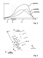
- Figure 3 shows a distribution d1 (MTBE) of all lines 13 of a set of lines 13 in consideration. Furthermore, in the diagram of Figure 3 , a distribution du(MTBE) of the stability metric MTBE of all lines having unsatisfactory service quality is shown.
- Figure 3 shows the distribution ds(MTBE) of the stability metric MTBE of all lines of the set of lines that offer satisfactory service quality.
- Subdividing the individual values of MTBE and the related lines 13 into satisfactory service quality and unsatisfactory service quality is accomplished by analysing the service quality information 49.
- this service quality information includes for each line of the set of lines the information on whether or not the line has satisfactory service quality.
- the individual pieces of physical line data 47 are tagged either with "unsatisfactory service quality" or "satisfactory service quality” so that the distributions du(MTBE) and ds(MTBE) can be calculated easily.
- two exemplary values of a threshold ⁇ u , ⁇ s are depicted.
- a decision can be made to which stability class of a plurality of stability classes a certain digital subscriber line 13 belongs.
- three different stability classes are considered, i.e. unstable U, risky R, and stable S.
- another number of different stability classes may be used.
- the method 45 comprises only two different stability classes, e. g. unstable U and stable S. In another embodiment, more than three different stability classes are considered.
- both distribution du(MTBE) and ds(MTBE) include infinite values of MTBE (no errors during the monitoring period).
- the stability classes U, R, S cannot be assigned accurately enough to individual values of the stability metric MTBE.
- the feature extraction block comprises a discriminant analysis, preferably a linear discriminant analysis.
- the principle of the discriminant analysis is illustrated in Figure 4.
- Figure 4 shows individual pieces of physical line data in a three-dimensional coordinate system. Pieces of physical line data tagged with "unsatisfactory” represented as hatched-points (some of them labelled with "u") and the pieces of physical line data tagged with "satisfactory” are drawn as solid black points (some of them labelled with "s”).
- the discriminant analysis comprises a coordinate transformation that maximises a discriminant measure.
- the transformed coordinate system (d1, d2, d3) is shown with solid line whereas the original coordinate system (CV, ES, SES) is shown with dashed lines.
- the feature extraction process 69 conceptually corresponds to a change of basis from the first basis or coordinate system (CV, ES, SES) to a second basis or coordinate system (d1, d2, d3).
- the change of basis or coordinate transformation corresponds to the optimum selection of the weight vector W opt by means of the discriminant analysis
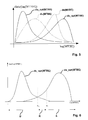
- Figure 5 shows the distributions of the stability metric MTBE when using the optimum weight vector line w opt .
- the distribution du_opt (MTBE) corresponds to the data tagged with "unsatisfactory”.
- the distribution ds_opt (MTBE) corresponds to the data tagged with "satisfactory”.
- the distributions du(MTBE) and ds(MTBE) related to the suboptimal choice of the weight vector w opt are shown with dotted line in Figure 5 .
- the diagram of Figure 5 is in logarithmic scale.
- determining the optimum weight vector w opt and the distribution of the stability metric MTBE according to the optimum weight vector w opt corresponds to a dimension transformation or reduction according to discriminant analysis, in particular linear discriminant analysis.
- Discriminant analysis is a well-known statistical method. Any suitable variant of discriminant analysis may be applied in block 69.
- the optimum weight vector w opt may be determined by minimizing the overlapping between the two distributions du(MTBE) and ds(MTBE).
- the difference of the two integrals in the above equation (3) characterizes the overlapping.
- the distributions f s and f u are determined for the stability metric MTBE s related to physical line data CV, ES, SES tagged with "satisfied” and for the stability metric MTBE u related to physical line data CV, ES, SES tagged with "unsatisfied", respectively.
- a fast implementation of such optimization process can be performed by a linear discriminant analysis directly with the CV/showtime, ES/showtime and SES/showtime values as input features by making use of the class-tagging for discrimination, as there is a monotonically relation between them and the term log (MTBE), as seen in equation (3).
- MTBE log
- any other suitable mathematical or statistical approach like quadratic discriminant analysis may be applied.
- a decision block 71 of the first optimisation process 63 determines the thresholds ⁇ u , ⁇ s .
- the other threshold ⁇ s could be chosen to guarantee for instance, that 95 % of the unsatisfactory lines are reported as not stable. Instead of 95 %, any other percentile can be applied.
- this second stability metric MTBR may also involved in the evaluation of the line stability and has an impact on the quality of the end user experience, i.e. the quality of service perceived by the end user.
- the second optimization process 65 has the same structure as the first optimization process 63.
- the stability metric MTBR is calculated from the number of resynchronisations Resync and/or the number of failed initialisations FI. Consequently, the filtering block 61 selects those pieces of physical line data 47 that include information about the number of resynchronisations and/or the number of failed initialisation for the second optimization process 65. In addition, the filtering block 61 selects those pieces of physical line data 47 containing information about the number of coding violations, the number of error seconds or the number of several error seconds for usage by the first optimization process 63.
- the second optimization process having the same structure as the first optimization process 63 includes a pre-processing block 67, a feature extraction block 69 and a decision block 71.
- the feature extraction block 69 of the second optimization process 65 applies the same approach as the feature extraction block 69 of the first optimization process 63 but different parameters Resync, FI are used as the physical line data 47 and a different stability metric MTBR is used. However the same algorithms, e.g.
- the linear or nonlinear discriminant analysis may be applied in the same manner as in the feature extraction block of the first optimization process.
- the stability metric MTBR may be calculated using the further weight vector s opt calculated in the feature extraction block 69 of the second optimization process 65:
- MTBE multiple stability metrics
- MTBR multiple stability metrics
- a decision criterion related to these multiple stability metrics can be determined.
- These threshold-based decision criterion may be expressed as follows: STABLE : MTBE T > ⁇ s and MTBR T > ⁇ s RISKY : ⁇ s > MTBE T > ⁇ u or ⁇ s > MTBR T > ⁇ u UNTABLE : MTBE T ⁇ ⁇ u or MTBR T > ⁇ u
- one decision criteria may be selected based on additional information.
- the addition information may be provided by the customer.
- the additional information may include a reason for a customer's complaint. That is, not only the classification provided by the end user of the line (relying on either "satisfactory” or "unsatisfactory") but also a reason of the end user feedback may be used by the method 45. Accordingly, a division of the problematic lines 13 according to this reason can be performed. For example, when the customer complains mainly about the repetitive amount of resynchronisation but is satisfied by the bit rate or quality of service, when the service is available, then the method 41 may apply the first optimization process 61 based on the MTBE metric.
- the method 45 may apply the second optimization process 65 based on the MTBR stability metric. Selecting the stability metric MTBE, MTBR and the respective optimization process 63, 65 based on the additional information further improves the accuracy of the method 45.
- the processes 63, 65 may be selected according to the type of service offered to the end user or actually used by the end user.
- the filtering block 61 may filter on either the high speed internet end users only or end users that use IPTV, as the quality of service constraints for these different types of services are fundamentally different. A more advanced distinction could even make use of the upper-protocol information, if such information is available.
- the present invention has been explained by embodiments related to exemplary parameters such as the stability metrics MTBE, MTBR and the physical line characteristics show time, CV, ES, SES, Resync, and FI.
- the present invention is not limited to these parameters or stability metrics.
- the embodiments described herein use these parameters because they are currently available in existing dynamic line management approaches. However, if in future implementations of dynamic line managements, new parameters presenting a potential relation with a quality of experience, get available, they may take part of the above-described equations and optimization approaches.
- the approach described above in connection with the stability metrics MTBE or MTBR may be applied accordingly to a further stability metric by replacing in the above equations or description the respective stability metric MTBE; MTBR and the respective physical line parameters CV, ES, SES; Resync, FI with the further stability metric and the physical line parameters on which the further stability metric depends.
- a further optimization process related to the further stability metric may be added to the method 45.
- the further optimization process is used instead of the first optimization process 63 and/or the second optimization process 65.
- the method 45 described herein uses feedback information about the quality of service perceived by the end users in order to derive at least one decision criterion for deciding on whether a telecommunication line is stable or unstable.
- the method 45 optimizes the computing of the stability metrics, e.g. by determining weight vectors w opt , s opt .
- the method 45 may provide a decision criterion in the form of at least one threshold ⁇ u , ⁇ s , ⁇ u, ⁇ s related to at least one stability metric MTBR, MTBE which constitute at least one decision criterion for determining whether or not the line is stable.
- Using these at least one decision criterion allows for more accurate assessment of the stability of the individual telecommunication lines 13 and therefore allows to improve the efficiency and the throughput of the access network 11.
Landscapes
- Engineering & Computer Science (AREA)
- Signal Processing (AREA)
- Computer Networks & Wireless Communication (AREA)
- Business, Economics & Management (AREA)
- General Business, Economics & Management (AREA)
- Physics & Mathematics (AREA)
- Probability & Statistics with Applications (AREA)
- Quality & Reliability (AREA)
- Telephonic Communication Services (AREA)
- Monitoring And Testing Of Exchanges (AREA)
- Data Exchanges In Wide-Area Networks (AREA)
Abstract
Description
- The present invention refers to a method and device evaluating the stability of communication over a telecommunication line. Furthermore, the present invention refers to a monitoring station comprising such a device and a computer program product arranged for carrying out such a method.
- With the increasing deployment of IPTV solutions, video-on-demand offers or triple-play services, both the system performance and the customer support becomes more and more exigent, particularly on digital subscriber lines (DSL). Disturbances or impairments on a digital subscriber line may heavily impact the bit rate on a physical access link provided by the digital subscriber line. A decrease of the bit rate would adversely impact the quality of service of the above-mentioned high bit rate services. Hence, it is of prime importance to be able to remotely diagnose reasons of the disturbances and impairments and take actions to improve the performance of the link, in particular to increase the bit rate. Automatic evaluating the performance of digital subscriber lines and taking action to resolve problems on the physical links provided by these lines is also referred to as Dynamic Line Management (DLM). Applying dynamic line management on a wire line access network helps the operators of the network to gain in service quality as well as to save money and time by not involving human inventions for all and every type of request that may occur in case of disturbances and impairments in the wire line access network.
- Moreover, recent technology evolutions in wire line access networks tend to push the bandwidth of the signal used on the digital subscriber lines higher. Major ADSLx technology use frequencies up to about 1.1 MHz. However, the current VDSL2 technology can be applied with bandwidths up to 17 MHz or even 30 MHz. Besides increasing the signal bandwidth, additional measures have been implemented in order to increase the bit rate of digital subscriber lines. As a consequence, digital subscriber lines have become more sensible to disturbances and impairments and more advanced solutions for dynamic line management are needed.
- Basically, dynamic line management monitors at least one parameter describing a physical characteristic of one or more digital subscriber lines and thereby dynamically accesses and monitors the stability of the line. A line is considered stable if transmission at a certain bit rate can be maintained during a sufficiently long time interval. Otherwise, the line is considered as unstable. Unstable lines typically have an unacceptable high rate of resynchronisations or an unacceptable high rate of coding violations or other transmission errors. If dynamic line management detects that a certain line is unstable, the maximum bit rate of that line may be reduced in order to stabilize that line. When monitoring and assessing the stability of a line, the quality of service (e. g. the bit rate under the stability assumption) should be improved and any unneeded decrease of the quality of service seen by the end user should be avoided. In particular, dynamic line management should not operate too conservatively and classify a line as unstable although the user does not feel any practical impacts on the quality of service, because a stabilisation action would typically reduce the bit rate or the latency of the line.
- It is known to assess the stability of a line, i.e. to establish if a line is stable or not, by defining stability metrics and thresholds related to these metrics using empirical rules. An exemplary known stability metric is the Mean Time Between Errors (MTBE) or the Mean Time Between Resynchronisations (MTBR). The MTBE describes a mean time during which a line has to wait before the transmission on that line is degraded by corrupted symbols, i.e. by physical layer symbols containing errors that may be caused by impulse noise or other disturbances. The MTBR describes a mean time before the modems of the customer premises equipment (CPE) and an access node of the network (e.g. a DSLAM) resynchronise spontaneously because of a weak quality of the link.
- A disadvantage of the known dynamic line management approach based on empirical rules lies in the inaccuracy of the empirical rules. Using the inaccurate empirical rules leads to suboptimal dynamic line management decisions. In particular, a bit rate of a line could be reduced by a stabilisation action although the reduction of the bit rate is actually not needed. In other words, the empirical rules may lead to a too conservative dynamic line management in terms of stability resulting in a comparatively low bit rate on the digital subscriber lines. By contrast, trying to increase the overall bit rate by simply implementing less conservative but still inaccurate empirical rules could harm to the overall stability of the lines and therefore could lead to the DLM not be seen as working well anymore.
- Thus, the object of the present invention is to provide a method and device for evaluating and/or estimating the stability of communication over a telecommunication line that allows for assessing the stability of the line more accurately and being more in concordance with the end-user quality of experience, thereby improving the performance (e. g. bit rate or latency) of the line without degrading its stability.
- According to an embodiment of the present invention, a method for evaluating the stability of communication over a telecommunication line is provided, the method comprising ascertaining physical line data characterizing a physical characteristic of each line of a fist set of subscriber lines; collecting service quality information describing a quality of a service provided over each line of a second set of subscriber lines; associating the service quality information related to at least one particular line with the physical line data related to the same particular line; and determining a decision criterion from the physical line data with associated service quality information, said decision criterion being determined for deciding to which stability class of a plurality of stability classes the digital subscriber line belongs. In an embodiment the first set and the second set of subscriber lines are identical. In another embodiment, the first set and the second set differ from each other; preferably, the first and the second set have at least some lines in common, i.e. are not disjoint. Ascertaining the physical line data may comprise retrieving the physical line data from at least one network element where the physical line data are created. Typically this network element is a node that is directly connected to the subscriber line, such as an access node or a DSL modem. In some embodiments, the physical line data are collected from multiple network elements (e.g. multiple access nodes) of an access network.
- By not only determining the physical line data but also associating the service quality information related to the line with the physical line and data and determining the decision criterion from both the physical line data and the quality information, an accurate decision criterion based on a sound statistical analysis is established. The decision criterion being based on correlating the physical line data with the service quality information, is more accurate than the empirical rules known from the prior art. As a consequence, a less conservative dynamic line management approach can be used without the risk of stability problems.
- Note that the service quality information describes the quality of the services (e.g. IP television, video on demand, Internet access, Voice over IP, etc) consumed by the individual users. The service quality information therefore refers to the service quality experienced by the users. In contrast to the service quality information, the physical line data includes physical parameters that are determined by a node connected to the line (e.g. an access node like a DSLAM or customer side termination node like a DSL modem) by measurement or logging and/or counting of events related to transmission errors.
- In an embodiment, the method comprises calculating at least one threshold for a stability metric of the line, the at least one threshold depending on the physical line data with associated service quality information. In this, embodiment, the at least one threshold constitutes the decision criterion. The at least one threshold can be compared with the stability metric in order to decide to which stability class the digital subscriber line belongs. However, the present invention is not limited to a threshold-based decision criterion. In another embodiment, the method may generate decision rules that can be processed in order to find the stability class.
- In a preferred embodiment, the plurality of stability classes corresponds to three classes: a class of stable lines, a class of risky lines and a class of unstable lines. In another embodiment, the plurality of classes consists of only two classes, e.g. the class of stable lines and the class of unstable lines.
- In an embodiment, the method comprises calculating at least one pair of thresholds. In this embodiment, the deciding to which stability class the line belongs may comprises comparing the stability metric with each threshold of the pair of thresholds. However, in another embodiment, the method does not include said comparing but only generates the threshold to be used by a different method or device.
- In an embodiment, the service quality information comprises an indication on whether or not the quality of service provided by the respective line is satisfactory. This information may be associated with the physical line data, e.g. by tagging the physical line data with the indication.
- In an embodiment, the service quality information is based on customer feedback. The customer feedback may be retrieved from a call centre or contact centre that has asked the customers if they consider the quality of the services provided over their digital subscriber lines as satisfactory or not. However any other suitable approach for collecting the service quality information may be applied, e.g. electronic customer feedback forms may be used.
- In an embodiment, the stability metric depends on multiple physical characteristics of the line. The physical characteristics may include a number CV of coding violations within a certain time interval (e.g. one day), a number of errored seconds ES or several errored seconds SES within the time interval, a number Resync of resynchronizations of the two modem circuitries connected to opposite ends of a line within the time interval and/or a number of failed initialisations FI of the line within the time interval. In a preferred embodiment, the stability metric is a Mean Time Between Errors (MTBE) or a Mean Time Between Resynchronisations (MTBR)
- In an embodiment, the method comprises adapting a calculation rule, e.g. an algorithm or an equation, for calculating the stability metric such that a discriminant measure related to the service quality information is optimized. Any type of discriminant measure may be applied. In a preferred embodiment, the discriminant measure characterizes an overlapping between a first distribution and a second distribution of the stability metric, with the first distribution being determined from pieces of the physical line data associated with service quality information indicating a satisfactory service quality and the second distribution being determined from pieces of the physical line data associated with service quality information indicating an unsatisfactory service quality.
- In an embodiment, the calculation rule includes a linear combination of the multiple physical characteristics and said adapting the calculation rule includes computing weight coefficients of the linear combination. Preferably, the method comprises calculating the at least one weight coefficient depending on the physical line data with associated quality information. In this embodiment, the weight coefficients are calculated by optimizing (maximizing or minimizing) the discriminant measure. In other words, the weight coefficient may be determined by a discriminant analysis.
- According to another embodiment of the present invention, a device for evaluating the stability of communication over a telecommunication line, is provided, the device being operable, preferably arranged, for determining physical line data characterizing a physical characteristic of each line of a fist set of subscriber lines; collecting service quality information describing a quality of a service provided over each line of a second set of subscriber lines; associating the service quality information related to at least one particular line with the physical line data related to the same particular line; and determining a decision criterion from the physical line data with associated service quality information, said decision criterion being determined for deciding to which stability class of a plurality of stability classes the digital subscriber line belongs.
- A device according to a preferred embodiment is operable, preferably programmed, for executing a method for evaluating the stability of communication over a telecommunication line described herein.
- According to yet another embodiment of the invention, a monitoring station for evaluating the stability of communication over a telecommunication line is provided, wherein the monitoring station comprises a device for evaluating the stability of communication over a telecommunication line described herein.
- According to still another embodiment, a computer program product, preferably a computer readable storage medium is provided, the computer program product comprising a computer program that is programmed for executing a method for evaluating the stability of communication over a telecommunication line described herein. The storage medium may include magnetic memory (e.g. hard disc drives or tapes), optical memory (e.g. optical discs) or semiconductor memory (e.g. Flash memory, ROM, RAM). Moreover, the computer program product may be provided by a server for download over a communication network like the Internet.
- Exemplary embodiments and further advantages of the present invention are shown in the Figures and described in detail hereinafter.
- Figure 1
- shows a communication network;
- Figure 2
- shows a block diagram of a method for evaluating the stability of the communication over telecommunication lines of the network shown in
Figure 1 ; - Figure 3
- shows diagrams of statistical distributions of stability metrics;
- Figure 4
- shows a coordinate transformation;
- Figure 5
- shows diagrams of statistical distributions of
Figure 3 and of statistical distributions with the coordination transformation applied; and - Figure 6
- shows diagrams of
Figure 5 and thresholds for the stability metrics. - The description and drawings merely illustrate the principles of the invention. It will thus be appreciated that those skilled in the art will be able to devise various arrangements that, although not explicitly described or shown herein, embody the principles of the invention and are included within its spirit and scope. Furthermore, all examples recited herein are principally intended expressly to be only for pedagogical purposes to aid the reader in understanding the principles of the invention and the concepts contributed by the inventors to furthering the art, and are to be construed as being without limitation to such specifically recited examples and conditions. Moreover, all statements herein reciting principles, aspects, and embodiments of the invention, as well as specific examples thereof, are intended to encompass equivalents thereof.
-
Figure 1 shows acommunication network 11 comprisingtelecommunication lines 13, at least onetelecommunication line 13 having a pair of electrical conductors. Afirst end 16 of theline 13 is connected to a network side termination node of thenetwork 11, further referred to asaccess node 17, and asecond end 18 of theline 13 is connected to a terminalside termination node 19 of thenetwork 11. The terminalside termination node 19 may be part of customer premises equipment (CPE 21) of thenetwork 11. - In the shown embodiment, the
telecommunication line 13 is a Digital Subscriber Line (DSL), such as VDSL2, ADSLx or the like. Consequently, theaccess node 17 may be a DSL Access Multiplexer (DSLAM) or another type of DSL access node. The terminalside termination node 19 may be a DSL modem or include a DSL modem. - The
access node 17 hasfirst modem circuitry 23 to which thefirst end 16 of thelines 13 is connected. In addition, theaccess node 17 has afirst controller 25 adapted for controlling the operation of theaccess node 17. In an embodiment, thefirst controller 25 is a programmable computer comprising aprocessor 27, e. g. a microprocessor, and astorage element 29, e.g. semiconductor memory. - The terminal
side termination node 19 includes second modem circuitry 33 to which thesecond end 18 of theline 13 is connected. Furthermore, the terminalside termination node 19 comprises asecond controller 31. Thesecond controller 31 may have the same basic configuration as thefirst controller 25, i.e. thesecond controller 31 may be a programmable computer and comprise aprocessor 27 and/or astorage element 29. - In the shown embodiment, at least some
lines 13 are part of abinder 35 and extend in parallel to each other. Thebinder 35 may comprise an electrically conductive, preferably metallic, shielding 38 that may be grounded as depicted inFigure 1 . Because at least some lines extend in parallel to each other in thebinder 35, crosstalk between thelines 13 may occur. - Furthermore, the
network 11 may comprise anoptional monitoring station 39 connected e. g. via aninterconnection network 41 to at least one of thenodes station 39 can communicate with at least one of thenodes access node 17. Thestation 39 comprises athird controller 43. Thethird controller 43 may have the same basic configuration as thefirst controller 25, i.e. thethird controller 43 may be a programmable computer and comprise aprocessor 27 and/or astorage element 29. In an exemplary embodiment, thestation 39 may be a server computer, a personal computer, a handheld computer such as a PDA or cell phone, etc. -
Figure 2 shows a block diagram of amethod 45 for evaluating the stability of communication of at least onetelecommunication line 13. Themethod 45 may be executed on themonitoring station 39. To this end, a computer program may be stored in thestorage element 29 of thethird controller 43. The computer program is programmed for executing themethod 45 when run by theprocessor 27 of thethird controller 43. However, themethod 45 may also be executed on a different network element of thenetwork 11, e. g. on theaccess node 17 and the program may be stored on thestorage element 29 of thesecond controller 25. - The
method 45 comprises ascertainingphysical line data 47. Thephysical line data 47 may comprise any value describing a physical characteristic of the line such as rate of coding violations CV, a number of error seconds ES within a certain time interval, a number of several errored seconds SES, the total show time showtime during the time interval, a number Resync of spontaneous resynchronisations within the certain time interval and/or a number of failed initialisations FI of a certain line within the time interval. Thephysical line data 47 may be retrieved from a network element - such as anaccess node 17 or the customer side termination node 19 - that is connected directly to aline 13. Preferably, themethod 45 comprises collecting the physical line data CV, ES, SES, showtime, Resync, FI frommultiple network elements network 11. - Furthermore, the
method 45 includes collectingservice quality information 49 describing a quality of service provided by eachline 13 considered by themethod 45. Theservice quality information 49 describes a quality of service perceived by the individual end users of the telecommunication lines 13. In the shown embodiment, theservice quality information 49 is determined by a call centre or contact centre. However, any suitable means for collecting information about the quality of service may be applied. For example, theservice quality information 49 may also be collected by using web-based forms that can be completed by the users. - Moreover, the
method 45 may acquireoperator data 51 describing the type of the service, (e. g. internet access, video-on-demand, Internet Protocol TV (IPTV), Voice over IP (VoIP), etc.) used on theindividual lines 13. Theoperator data 51 may also include information specific to a service of a certain type such as type of video and/or audio codec, bit rate requirements or the amount of data to be transferred over theline 13. - The
step 53 of themethod 45 associates theservice quality information 49 related to at least oneparticular line 13 with thephysical line data 47 related to the sameparticular line 13. In the shown embodiment,step 53 is a tagging step that tags the pieces ofphysical line data 47 with theservice quality information 49 related to the same line. Consequently, step 53 combines thephysical line data 47 that may have been generated by means of measurements at least at atermination node service quality information 49 generated from customer feedback collected e. g. via a call centre. In an embodiment, the taggingstep 53 also associates theoperator data 51 related to the sameparticular line 13 with thephysical line data 47. However, using theoperator data 51 is optional. In another embodiment, themethod 45 does not use theoperator data 51. - In the shown embodiment, the
service quality information 49 related to aparticular line 13 is aggregated information that describes whether or not the customer is satisfied with the service or not. That is, the service quality information may comprise a binary value related to theindividual lines 13 that describes the service quality. - A result of
step 53 consists in taggeddata 57 including thephysical line data 47 associated with theservice quality information 49 and optionally with theoperator data 51. In the shown embodiment, the tagging 53 is implemented by physically adding theservice quality information 49 and optionally theoperator data 51 as a tag to the individual pieces ofphysical line data 47. However, in other embodiments any other suitable technical means for associating thephysical line data 47, theservice quality information 49 and optionally theoperator data 51 related to thissame line 13 with each other can be used. For example, thedata - In an embodiment, the
method 45 comprises afiltering block 61 for filtering the taggeddata 57 to be used for acertain optimisation process filtering block 61 may select only those taggeddata 57 that include a certain physical characteristic and/or that are tagged withcertain operator data 51. For example, thefiltering block 61 may select taggeddata 57 related to a certain type of service.Block 61 may even be more selective and restricting the selected data to a certain characteristic of the service such as the bit rate or type of codec, etc. - The shown
exemplary method 45 includes two exemplary optimisation processes 63, 65 related to different stability metrics. Generally, a stability metric is a value calculated from one or more physical line characteristics that describe the level of stability of theline 13. Examples of stability metric are the Mean Time Between Errors (MTBE) and the Mean Time Between Resynchronisations (MTBR). Afirst optimisation process 63 determines thresholds Θu, Θs. The thresholds Θu, Θs constitute decision criterion for classifying theindividual lines 13 according to their stability. The thresholds Θu, Θs are related to MTBE. In addition, thefirst optimisation process 63 calculates weights Wopt=[w1, w2, w3] to be used to calculate the performance metric MTBE. Both the thresholds Θu, Θs as well as Wopt are calculated depending on thephysical line data 47, theservice quality information 49 and optionally theoperator data 51 rather than relying than empirical rules. In the shown embodiment, the first optimisation process uses the taggeddata 57 that may optionally be filtered by thefiltering block 61. - A
second optimisation process 65 of themethod 41 determines a further decision criterion related to another stability metric, i.e. the mean time between resynchronisations MTBR. Further thresholds Γu, Γs constitute the further decision criterion related to the MTBR. In addition, thesecond optimisation process 65 determines further weights Sopt = [s1, s2] to be used for calculating the stability metric MTBR. - Note that the present invention is not limited to the two exemplary optimisation processes 63, 65 and the related decision criterion. Instead of thresholds or in addition to the thresholds, any other type of decision criterion can be derived from the
physical line data 47 with the associatedquality information 49. For example, rules or algorithms may be automatically derived from the physical line data with the associated quality information. Moreover, the present invention is not limited to the stability metrics MTBE and MTBR. Any other stability metric can be applied. Furthermore, any other metric depending on the physical line data may be used. - In the following, the
first optimisation process 63 is explained in more detail. Anoptional pre-processing block 67 processes the filtered taggeddata 57. The processing by thepre-processing block 67 may include grouping the taggeddata 57 belonging to the same time interval T, e. g. one day, or to filter over a minimum acceptable time interval T, to improve the reliability of the estimations. - A
feature extraction block 69 determines the weights Wopt as well as values of the stability metric MTBE associated with theservice quality information 49 and optionally theoperator data 51. In the shown embodiment, block 69 generates tagged values of the stability metric MTBE with the tag including pieces of theservice quality information 49 and/or theoperator data 51. - The stability metric MTBE may be calculated according to the following equation

- The first
feature extraction block 69 selects the weights Wopt = [W1, W2, W3] such that the stability metric MTBE allows making the most suitable distinction between stability classes. - In order to illustrate the effect of the selection of the weights Wopt to the possibility to make a good distinction between the classes, a simple but suboptimal choice of the weights that might have been the result of empirical considerations, shall be considered. When using e.g. a weight vector Wopt =[1,0, 0] then the MTBE is calculated as follows

- Where the considered time interval is T = 1 day.
-
Figure 3 shows a distribution d1 (MTBE) of alllines 13 of a set oflines 13 in consideration. Furthermore, in the diagram ofFigure 3 , a distribution du(MTBE) of the stability metric MTBE of all lines having unsatisfactory service quality is shown. - Finally,
Figure 3 shows the distribution ds(MTBE) of the stability metric MTBE of all lines of the set of lines that offer satisfactory service quality. Subdividing the individual values of MTBE and therelated lines 13 into satisfactory service quality and unsatisfactory service quality is accomplished by analysing theservice quality information 49. In the shown embodiment, this service quality information includes for each line of the set of lines the information on whether or not the line has satisfactory service quality. As a consequence, the individual pieces ofphysical line data 47 are tagged either with "unsatisfactory service quality" or "satisfactory service quality" so that the distributions du(MTBE) and ds(MTBE) can be calculated easily. InFigure 3 , two exemplary values of a threshold θu, θs are depicted. By comparing a value of the stability metric MTBE with the thresholds θu, θs, a decision can be made to which stability class of a plurality of stability classes a certaindigital subscriber line 13 belongs. In all embodiments described herein in detail, three different stability classes are considered, i.e. unstable U, risky R, and stable S. However, in other embodiments another number of different stability classes may be used. In one embodiment, themethod 45 comprises only two different stability classes, e. g. unstable U and stable S. In another embodiment, more than three different stability classes are considered. - As can be seen in
Figure 3 , when choosing the weights wopt as described above, there is a big overlap between the two distributions du(MTBE) and ds(MTBE). In particular, both distribution du(MTBE) and ds(MTBE) include infinite values of MTBE (no errors during the monitoring period). As a consequence, the stability classes U, R, S cannot be assigned accurately enough to individual values of the stability metric MTBE. In order to allow for more reliable and accurate assignment of the stability classes U, R, S to the individual lines or values of MTBE, the firstfeature extraction block 69 of themethod 45 determines an optimum combination of physical line characteristics CV, ES, SES by appropriately determining the weight vector w opt = [w 1, w 2, w 3] so that the most suitable distinction between the stability classes can be carried out. - In order to determine the optimum weight vector, the feature extraction block comprises a discriminant analysis, preferably a linear discriminant analysis. The principle of the discriminant analysis is illustrated in
Figure 4. Figure 4 shows individual pieces of physical line data in a three-dimensional coordinate system. Pieces of physical line data tagged with "unsatisfactory" represented as hatched-points (some of them labelled with "u") and the pieces of physical line data tagged with "satisfactory" are drawn as solid black points (some of them labelled with "s"). The discriminant analysis comprises a coordinate transformation that maximises a discriminant measure. The transformed coordinate system (d1, d2, d3) is shown with solid line whereas the original coordinate system (CV, ES, SES) is shown with dashed lines. Thus, thefeature extraction process 69 conceptually corresponds to a change of basis from the first basis or coordinate system (CV, ES, SES) to a second basis or coordinate system (d1, d2, d3). The change of basis or coordinate transformation corresponds to the optimum selection of the weight vector Wopt by means of the discriminant analysis -
Figure 5 shows the distributions of the stability metric MTBE when using the optimum weight vector line wopt. The distribution du_opt (MTBE) corresponds to the data tagged with "unsatisfactory". The distribution ds_opt (MTBE) corresponds to the data tagged with "satisfactory". The distributions du(MTBE) and ds(MTBE) related to the suboptimal choice of the weight vector wopt are shown with dotted line inFigure 5 . The diagram ofFigure 5 is in logarithmic scale. - Basically, determining the optimum weight vector wopt and the distribution of the stability metric MTBE according to the optimum weight vector wopt corresponds to a dimension transformation or reduction according to discriminant analysis, in particular linear discriminant analysis. Discriminant analysis is a well-known statistical method. Any suitable variant of discriminant analysis may be applied in
block 69. - In an embodiment, the optimum weight vector wopt may be determined by minimizing the overlapping between the two distributions du(MTBE) and ds(MTBE). The overlapping is a discriminant measure used in the exemplary embodiment described herein. Consequently, the following optimization problem has to be solved:

- The difference of the two integrals in the above equation (3) characterizes the overlapping. The distributions fs and fu are determined for the stability metric MTBEs related to physical line data CV, ES, SES tagged with "satisfied" and for the stability metric MTBEu related to physical line data CV, ES, SES tagged with "unsatisfied", respectively.
- In an embodiment, a fast implementation of such optimization process can be performed by a linear discriminant analysis directly with the CV/showtime, ES/showtime and SES/showtime values as input features by making use of the class-tagging for discrimination, as there is a monotonically relation between them and the term log (MTBE), as seen in equation (3). In another embodiment, any other suitable mathematical or statistical approach like quadratic discriminant analysis may be applied.
- Based on the optimum weight wopt and the distributions du_opt(MTBE) and ds_opt(MTBE), a
decision block 71 of thefirst optimisation process 63 determines the thresholds θu, θs. In the shown embodiment, the threshold θu is defined as being the MTBE-value where the two distributions du_opt(MTBE) and ds_opt(MTBE) intersect. Accordingly, the θu is shown inFigure 6 at a value for MTBE where du, opt (MTBE) = ds, opt (MTBE). The other threshold θs could be chosen to guarantee for instance, that 95 % of the unsatisfactory lines are reported as not stable. Instead of 95 %, any other percentile can be applied. Mathematically, this is expressed e.g. as follows:
- As can be seen on
Figure 2 , the generic concept explained above in connection with the stability metric MTBE which thefirst optimization process 63 is based, can also applied to the stability metric MTBR in thesecond optimisation process 65 accordingly. In other words, this second stability metric MTBR may also involved in the evaluation of the line stability and has an impact on the quality of the end user experience, i.e. the quality of service perceived by the end user. - The
second optimization process 65 has the same structure as thefirst optimization process 63. In the shown embodiment, the stability metric MTBR is calculated from the number of resynchronisations Resync and/or the number of failed initialisations FI. Consequently, thefiltering block 61 selects those pieces ofphysical line data 47 that include information about the number of resynchronisations and/or the number of failed initialisation for thesecond optimization process 65. In addition, thefiltering block 61 selects those pieces ofphysical line data 47 containing information about the number of coding violations, the number of error seconds or the number of several error seconds for usage by thefirst optimization process 63. - The second optimization process having the same structure as the
first optimization process 63 includes apre-processing block 67, afeature extraction block 69 and adecision block 71. Thesecond optimization process 65 differs from thefirst optimization process 63 in that different physical line data Resync, FI are used and the further thresholds Γu, Γs as well as the further weights sopt = [s1, s2] are calculated. Thefeature extraction block 69 of thesecond optimization process 65 applies the same approach as thefeature extraction block 69 of thefirst optimization process 63 but different parameters Resync, FI are used as thephysical line data 47 and a different stability metric MTBR is used. However the same algorithms, e.g. the linear or nonlinear discriminant analysis may be applied in the same manner as in the feature extraction block of the first optimization process. The stability metric MTBR may be calculated using the further weight vector sopt calculated in thefeature extraction block 69 of the second optimization process 65:
- When using multiple stability metrics MTBE, MTBR, a decision criterion related to these multiple stability metrics can be determined. These threshold-based decision criterion may be expressed as follows:

- Instead of using multiple decision criteria simultaneously, as in equation (6), in another embodiment, one decision criteria may be selected based on additional information. The addition information may be provided by the customer. For example, the additional information may include a reason for a customer's complaint. That is, not only the classification provided by the end user of the line (relying on either "satisfactory" or "unsatisfactory") but also a reason of the end user feedback may be used by the
method 45. Accordingly, a division of theproblematic lines 13 according to this reason can be performed. For example, when the customer complains mainly about the repetitive amount of resynchronisation but is satisfied by the bit rate or quality of service, when the service is available, then themethod 41 may apply thefirst optimization process 61 based on the MTBE metric. By contrast, when the end-user complains about e. g. the presence of artefacts in the IPTV service or about low throughputs when downloading data, but is not annoyed by repetitive resynchronisations, themethod 45 may apply thesecond optimization process 65 based on the MTBR stability metric. Selecting the stability metric MTBE, MTBR and therespective optimization process method 45. - In order to further improve the
optimization process processes filtering block 61 may filter on either the high speed internet end users only or end users that use IPTV, as the quality of service constraints for these different types of services are fundamentally different. A more advanced distinction could even make use of the upper-protocol information, if such information is available. - The present invention has been explained by embodiments related to exemplary parameters such as the stability metrics MTBE, MTBR and the physical line characteristics show time, CV, ES, SES, Resync, and FI. However, the present invention is not limited to these parameters or stability metrics. The embodiments described herein use these parameters because they are currently available in existing dynamic line management approaches. However, if in future implementations of dynamic line managements, new parameters presenting a potential relation with a quality of experience, get available, they may take part of the above-described equations and optimization approaches. In particular, the approach described above in connection with the stability metrics MTBE or MTBR may be applied accordingly to a further stability metric by replacing in the above equations or description the respective stability metric MTBE; MTBR and the respective physical line parameters CV, ES, SES; Resync, FI with the further stability metric and the physical line parameters on which the further stability metric depends. Thus, a further optimization process related to the further stability metric may be added to the
method 45. In an embodiment the further optimization process is used instead of thefirst optimization process 63 and/or thesecond optimization process 65. - To sum up, the
method 45 described herein uses feedback information about the quality of service perceived by the end users in order to derive at least one decision criterion for deciding on whether a telecommunication line is stable or unstable. Preferably, themethod 45 optimizes the computing of the stability metrics, e.g. by determining weight vectors wopt, sopt. Furthermore, themethod 45 may provide a decision criterion in the form of at least one threshold θu, θs, Γu, Γs related to at least one stability metric MTBR, MTBE which constitute at least one decision criterion for determining whether or not the line is stable. Using these at least one decision criterion allows for more accurate assessment of the stability of theindividual telecommunication lines 13 and therefore allows to improve the efficiency and the throughput of theaccess network 11.
Claims (14)
- Method (45) for evaluating the stability of communication over a telecommunication line (13), the method (45) comprising- ascertaining physical line data (47) characterizing a physical characteristic (CV, ES, SES; Resync, FI) of each line (13) of a fist set of subscriber lines;- collecting service quality information (49) describing a quality of a service provided over each line (13) of a second set of subscriber lines;- associating (53) the service quality information (47) related to at least one particular line (13) with the physical line data related to the same particular line (13); and- determining (63, 65) a decision criterion (Θu, Θs, Γu, Γs) from the physical line data (47) with associated service quality information (49), said decision criterion (Θu, Θs, Γu, Γs) being determined for deciding to which stability class (S, R, U) of a plurality of stability classes (S, R, U) the digital subscriber line (13) belongs.
- Method (45) according to claim 1, wherein the method (45) comprises calculating at least one threshold (Θu, Θs, Γu, Γs) for a stability metric (MTBE, MTBR) of the line (13), the at least one threshold depending on the physical line data (47) with associated service quality information (49).
- Method (45) according to claim 1 or 2, wherein the plurality of stability classes corresponds to three classes: a class of stable lines (S), a class of risky lines (R) and a class of unstable lines (U).
- Method (45) according to claim 3, wherein the method (45) comprises calculating (71) at least one pair (Θu, Θs; Γu, Γs) of thresholds and/or wherein the deciding to which stability class (S, R, U) the line (13) belongs comprises comparing the stability metric (MTBE, MTBR) with each threshold (Θu, Θs; Γu, Γs) of the pair of thresholds.
- Method (45) according to one of the precedent claims, wherein the service quality information (49) comprises an indication on whether or not the quality of service provided by the respective line (13) is satisfactory.
- Method (45) according to one of the precedent claims, wherein the service quality information (49) is based on customer feedback.
- Method (45) according to one of claims 2 to 6, wherein the stability metric (MTBE, MTBR) depends on multiple physical characteristics (CV, ES, SES; Resync, FI) of the line (13).
- Method (45) according to one of claims 2 to 7, wherein the method comprises adapting a calculation rule (wopt, sopt) for calculating the stability metric (MTBE, MTBR) such that a discriminant measure related to the service quality information (49) is optimized.
- Method (45) according to claim 8, wherein the calculation rule includes a linear combination of the multiple physical characteristics (CV, ES, SES; Resync, FI) and said adapting the calculation rule includes computing weight coefficients (wopt, sopt) of the linear combination.
- Method (45) according to claim 9, wherein the method (45) comprises calculating the at least one weight coefficient (wopt, sopt) depending on the physical line data (47) with associated quality information.
- Device (25, 31, 43) for monitoring the stability of communication over a telecommunication line (13), device (25, 31, 43) being operable for- ascertaining physical line data (47) characterizing a physical characteristic (CV, ES, SES; Resync, FI) of each line (13) of a fist set of subscriber lines;- collecting service quality information (49) describing a quality of a service provided over each line (13) of a second set of subscriber lines;- associating (53) the service quality information (47) related to at least one particular line (13) with the physical line data related to the same particular line (13); and- determining (63, 65) a decision criterion (Θu, Θs, Γu, Γs) from the physical line data (47) with associated service quality information (49), said decision criterion (Θu, Θs, Γu, Γs) being determined for deciding to which stability class (S, R, U) of a plurality of stability classes (S, R, U) the digital subscriber line (13) belongs.
- Device (25, 31, 43) according to claim 11, wherein the device (25, 31, 43) is operable, preferably programmed, for executing a method (45) according to one of claims 1 to 10.
- Monitoring station (39) for monitoring the stability of communication over a telecommunication line, wherein the monitoring station comprises a device (43) according to claim 11 or 12
- Computer program product, preferably a computer readable storage medium (29), comprising a computer program that is programmed for executing a method (45) according to one of claims 1 to 10 when run on a computer.
Priority Applications (2)
| Application Number | Priority Date | Filing Date | Title |
|---|---|---|---|
| EP13305678.8A EP2806594B1 (en) | 2013-05-24 | 2013-05-24 | Method and device for evaluating the stability of a telecommunication line |
| PCT/EP2014/057070 WO2014187609A1 (en) | 2013-05-24 | 2014-04-08 | Method and device for evaluating the stability of a telecommunication line |
Applications Claiming Priority (1)
| Application Number | Priority Date | Filing Date | Title |
|---|---|---|---|
| EP13305678.8A EP2806594B1 (en) | 2013-05-24 | 2013-05-24 | Method and device for evaluating the stability of a telecommunication line |
Publications (2)
| Publication Number | Publication Date |
|---|---|
| EP2806594A1 true EP2806594A1 (en) | 2014-11-26 |
| EP2806594B1 EP2806594B1 (en) | 2016-08-10 |
Family
ID=48577662
Family Applications (1)
| Application Number | Title | Priority Date | Filing Date |
|---|---|---|---|
| EP13305678.8A Not-in-force EP2806594B1 (en) | 2013-05-24 | 2013-05-24 | Method and device for evaluating the stability of a telecommunication line |
Country Status (2)
| Country | Link |
|---|---|
| EP (1) | EP2806594B1 (en) |
| WO (1) | WO2014187609A1 (en) |
Cited By (28)
| Publication number | Priority date | Publication date | Assignee | Title |
|---|---|---|---|---|
| EP3091724A1 (en) * | 2015-05-05 | 2016-11-09 | Alcatel Lucent | Method and device for determining the stability of a digital subscriber line |
| CN106325856A (en) * | 2016-08-10 | 2017-01-11 | 杭州玳数科技有限公司 | Method and system for realizing visualized editing and data presentation of Elasticsearch Dsl rule |
| EP3163784A1 (en) * | 2015-10-29 | 2017-05-03 | Alcatel Lucent | Method and device for controlling a digital subscriber line |
| EP3331198A1 (en) * | 2016-12-02 | 2018-06-06 | Alcatel Lucent | Method and device for monitoring a dsl network |
| USD825655S1 (en) | 2016-10-31 | 2018-08-14 | Ward Kraft, Inc. | Combination wristband and label form |
| US10249221B2 (en) | 2015-10-29 | 2019-04-02 | Ward Kraft, Inc. | Combination wristband and label form |
| US10325525B1 (en) | 2015-06-12 | 2019-06-18 | Ward Kraft, Inc. | Combination wristband and label form |
| USD853481S1 (en) | 2016-10-31 | 2019-07-09 | Ward Kraft, Inc. | Combination wristband and label form |
| USD853483S1 (en) | 2018-11-02 | 2019-07-09 | Ward Kraft, Inc. | Combination wristband and label form |
| GB2572381A (en) * | 2018-03-28 | 2019-10-02 | British Telecomm | DSL line fault identification |
| USD910113S1 (en) | 2018-11-02 | 2021-02-09 | Ward-Kraft, Inc. | Combination wristband and label form |
| US10997874B1 (en) | 2015-10-29 | 2021-05-04 | Ward-Kraft, Inc. | Combination wristband and label form |
| EP3829110A1 (en) * | 2019-11-28 | 2021-06-02 | Zhilabs S.L. | Self-managing a network for maximizing quality of experience |
| USD923706S1 (en) | 2019-08-01 | 2021-06-29 | Ward-Kraft, Inc. | Combination wristband and label form |
| USD930742S1 (en) | 2020-02-18 | 2021-09-14 | Ward-Kraft, Inc. | Combination windowed wristband label form with extender |
| US11232719B1 (en) | 2019-09-04 | 2022-01-25 | Ward-Kraft, Inc. | Single ply wristband with printable coating |
| USD941917S1 (en) | 2020-02-18 | 2022-01-25 | Ward-Kraft, Inc. | Combination wristband label form with extender |
| US11238759B1 (en) | 2015-10-29 | 2022-02-01 | Ward-Kraft, Inc. | Single ply wristband with printable coating |
| USD961675S1 (en) | 2020-02-18 | 2022-08-23 | Ward-Kraft, Inc. | Combination wristband label form with tags |
| USD967253S1 (en) | 2020-02-26 | 2022-10-18 | Ward-Kraft, Inc. | Wristband form with extender |
| USD967254S1 (en) | 2020-03-06 | 2022-10-18 | Ward-Kraft, Inc. | Wristband form with extender |
| USD970611S1 (en) | 2021-04-13 | 2022-11-22 | Ward-Kraft, Inc. | Combination wristband with slots and label form |
| USD970610S1 (en) | 2021-04-13 | 2022-11-22 | Ward-Kraft, Inc. | Business form having a wristband with slots |
| USD970609S1 (en) | 2021-04-13 | 2022-11-22 | Ward-Kraft, Inc. | Combination wristband with slots and label form |
| US11557228B1 (en) | 2015-10-29 | 2023-01-17 | Ward-Kraft, Inc. | Wristband and label form |
| US11587470B1 (en) | 2015-06-12 | 2023-02-21 | Rekon, Llc | Business form and methods of making and using same |
| USD988404S1 (en) | 2020-02-14 | 2023-06-06 | Rekon, Llc | Wristband label form with single strap wristbands |
| US11715394B1 (en) | 2015-10-29 | 2023-08-01 | Rekon, Llc | Wristband label form with uneven lamination panels |
Citations (1)
| Publication number | Priority date | Publication date | Assignee | Title |
|---|---|---|---|---|
| US20060221849A1 (en) * | 2005-03-31 | 2006-10-05 | Sbc Knowledge Ventures, L.P. | Method of selecting a profile of a broadband communication line |
-
2013
- 2013-05-24 EP EP13305678.8A patent/EP2806594B1/en not_active Not-in-force
-
2014
- 2014-04-08 WO PCT/EP2014/057070 patent/WO2014187609A1/en not_active Ceased
Patent Citations (1)
| Publication number | Priority date | Publication date | Assignee | Title |
|---|---|---|---|---|
| US20060221849A1 (en) * | 2005-03-31 | 2006-10-05 | Sbc Knowledge Ventures, L.P. | Method of selecting a profile of a broadband communication line |
Non-Patent Citations (4)
| Title |
|---|
| F. FESSANT ET AL: "A Complete Data Mining process to Manage the QoS of ADSL Services", WAITS 2012, 28 August 2012 (2012-08-28), XP055085359, Retrieved from the Internet <URL:http://www.engpaper.com/data-mining-research-papers-2012-section-3.htm> [retrieved on 20131025] * |
| JOCHEN MAES ET AL: "Autonomous dynamic optimization for digital subscriber line networks", BELL LABS TECHNICAL JOURNAL, WILEY, CA, US, vol. 15, no. 3, 1 December 2010 (2010-12-01), pages 119 - 129, XP001558908, ISSN: 1089-7089, DOI: 10.1002/BLTJ.20460 * |
| JOCHEN MAES ET AL: "Maximizing Digital Subscriber Line Performance", BELL LABS TECHNICAL JOURNAL, WILEY, CA, US, vol. 13, no. 1, 1 March 2008 (2008-03-01), pages 105 - 116, XP002591690, ISSN: 1089-7089, [retrieved on 20080515], DOI: 10.1002/BLTJ.20285 * |
| V. LEMAIRE ET AL: "Gestion de la QoS des services ADSL à l'aide d'un processus de data mining", 11 CONFÉRENCE INTERNATIONALE FRANCOPHONE SUR L'EXTRACTION ET LA GESTION DES CONNAISSANCES, 25 January 2011 (2011-01-25), XP055085365, Retrieved from the Internet <URL:http://www2.lirmm.fr/ecai2012/images/stories/ecai_doc/pdf/workshop/W38_WAITS2012_Proceedings.pdf#page=7> [retrieved on 20131025] * |
Cited By (36)
| Publication number | Priority date | Publication date | Assignee | Title |
|---|---|---|---|---|
| EP3091724A1 (en) * | 2015-05-05 | 2016-11-09 | Alcatel Lucent | Method and device for determining the stability of a digital subscriber line |
| US10325525B1 (en) | 2015-06-12 | 2019-06-18 | Ward Kraft, Inc. | Combination wristband and label form |
| US11587470B1 (en) | 2015-06-12 | 2023-02-21 | Rekon, Llc | Business form and methods of making and using same |
| US12387626B1 (en) | 2015-06-12 | 2025-08-12 | Rekon, Llc | Business form and methods of making and using same |
| US12170033B1 (en) | 2015-10-29 | 2024-12-17 | Rekon, Llc | Single ply wristband with printable coating |
| US11557228B1 (en) | 2015-10-29 | 2023-01-17 | Ward-Kraft, Inc. | Wristband and label form |
| US10297170B2 (en) | 2015-10-29 | 2019-05-21 | Ward Kraft, Inc. | Combination wristband and label form |
| US11694580B2 (en) | 2015-10-29 | 2023-07-04 | Rekon, Llc | Single ply wristband with printable coating |
| US11715394B1 (en) | 2015-10-29 | 2023-08-01 | Rekon, Llc | Wristband label form with uneven lamination panels |
| US10249221B2 (en) | 2015-10-29 | 2019-04-02 | Ward Kraft, Inc. | Combination wristband and label form |
| US12142166B1 (en) | 2015-10-29 | 2024-11-12 | Rekon, Llc | Wristband label form with uneven lamination panels |
| US11651708B1 (en) | 2015-10-29 | 2023-05-16 | Rekon, Llc | Combination wristband and label form |
| EP3163784A1 (en) * | 2015-10-29 | 2017-05-03 | Alcatel Lucent | Method and device for controlling a digital subscriber line |
| US11238759B1 (en) | 2015-10-29 | 2022-02-01 | Ward-Kraft, Inc. | Single ply wristband with printable coating |
| US10997874B1 (en) | 2015-10-29 | 2021-05-04 | Ward-Kraft, Inc. | Combination wristband and label form |
| CN106325856A (en) * | 2016-08-10 | 2017-01-11 | 杭州玳数科技有限公司 | Method and system for realizing visualized editing and data presentation of Elasticsearch Dsl rule |
| CN106325856B (en) * | 2016-08-10 | 2019-08-20 | 杭州玳数科技有限公司 | A kind of method and system for realizing Elasticsearch Dsl rule visual edit and data exhibiting |
| USD853481S1 (en) | 2016-10-31 | 2019-07-09 | Ward Kraft, Inc. | Combination wristband and label form |
| USD825655S1 (en) | 2016-10-31 | 2018-08-14 | Ward Kraft, Inc. | Combination wristband and label form |
| EP3331198A1 (en) * | 2016-12-02 | 2018-06-06 | Alcatel Lucent | Method and device for monitoring a dsl network |
| GB2572381B (en) * | 2018-03-28 | 2021-04-14 | British Telecomm | DSL line fault identification |
| GB2572381A (en) * | 2018-03-28 | 2019-10-02 | British Telecomm | DSL line fault identification |
| USD853483S1 (en) | 2018-11-02 | 2019-07-09 | Ward Kraft, Inc. | Combination wristband and label form |
| USD910113S1 (en) | 2018-11-02 | 2021-02-09 | Ward-Kraft, Inc. | Combination wristband and label form |
| USD923706S1 (en) | 2019-08-01 | 2021-06-29 | Ward-Kraft, Inc. | Combination wristband and label form |
| US11232719B1 (en) | 2019-09-04 | 2022-01-25 | Ward-Kraft, Inc. | Single ply wristband with printable coating |
| EP3829110A1 (en) * | 2019-11-28 | 2021-06-02 | Zhilabs S.L. | Self-managing a network for maximizing quality of experience |
| USD988404S1 (en) | 2020-02-14 | 2023-06-06 | Rekon, Llc | Wristband label form with single strap wristbands |
| USD930742S1 (en) | 2020-02-18 | 2021-09-14 | Ward-Kraft, Inc. | Combination windowed wristband label form with extender |
| USD941917S1 (en) | 2020-02-18 | 2022-01-25 | Ward-Kraft, Inc. | Combination wristband label form with extender |
| USD961675S1 (en) | 2020-02-18 | 2022-08-23 | Ward-Kraft, Inc. | Combination wristband label form with tags |
| USD967253S1 (en) | 2020-02-26 | 2022-10-18 | Ward-Kraft, Inc. | Wristband form with extender |
| USD967254S1 (en) | 2020-03-06 | 2022-10-18 | Ward-Kraft, Inc. | Wristband form with extender |
| USD970609S1 (en) | 2021-04-13 | 2022-11-22 | Ward-Kraft, Inc. | Combination wristband with slots and label form |
| USD970610S1 (en) | 2021-04-13 | 2022-11-22 | Ward-Kraft, Inc. | Business form having a wristband with slots |
| USD970611S1 (en) | 2021-04-13 | 2022-11-22 | Ward-Kraft, Inc. | Combination wristband with slots and label form |
Also Published As
| Publication number | Publication date |
|---|---|
| WO2014187609A1 (en) | 2014-11-27 |
| EP2806594B1 (en) | 2016-08-10 |
Similar Documents
| Publication | Publication Date | Title |
|---|---|---|
| EP2806594B1 (en) | Method and device for evaluating the stability of a telecommunication line | |
| EP2633644B1 (en) | Service performance in communications network | |
| Jin et al. | Nevermind, the problem is already fixed: proactively detecting and troubleshooting customer dsl problems | |
| JP5555488B2 (en) | Method and apparatus for characterizing a communication system by combining data from multiple sources | |
| CN101133632B (en) | DSL system estimation including known DSL line scanning and bad splice detection capability | |
| WO2021072890A1 (en) | Traffic abnormality monitoring method and apparatus based on model, and device and storage medium | |
| EP3694149B1 (en) | Network quality determining method and apparatus | |
| CN112291107B (en) | Network analysis program, network analysis device, and network analysis method | |
| US12294888B2 (en) | Method and system for managing mobile network congestion | |
| US20120203788A1 (en) | Network management system and method for identifying and accessing quality of service issues within a communications network | |
| EP3454506A1 (en) | Method and device for monitoring a telecommunication network | |
| CN115843061A (en) | User perception evaluation method, device, storage medium and electronic device | |
| CN113517990B (en) | A method and device for predicting network net promoter score NPS | |
| EP3024176A1 (en) | Method for assessing a quality of service of a data communication over a data communications line, a related system and devices | |
| EP3391295B1 (en) | Autonomic method for managing a computing system | |
| CN111582628A (en) | Quality evaluation method and device | |
| US9473376B2 (en) | Method and server for determining home network quality | |
| EP2999202A1 (en) | A device and the related method for estimating the stability of a digital subscriber line | |
| KR100812946B1 (en) | Service Quality Management System and Method in Mobile Communication Network | |
| EP4578165B1 (en) | Unified service quality model for mobile networks | |
| JP4668851B2 (en) | Quality class determination apparatus, quality class determination method, and program | |
| CN105144596A (en) | Identifying line faults using regression analysis on near and far end errors | |
| US10938981B2 (en) | Method and apparatus for determining a bridged tap length | |
| US20240422081A1 (en) | Network Analytics System with Data Loss Detection | |
| CN121486286A (en) | A method, apparatus, equipment, and medium for optimizing data transmission in power grid communication networks. |
Legal Events
| Date | Code | Title | Description |
|---|---|---|---|
| PUAI | Public reference made under article 153(3) epc to a published international application that has entered the european phase |
Free format text: ORIGINAL CODE: 0009012 |
|
| 17P | Request for examination filed |
Effective date: 20140121 |
|
| AK | Designated contracting states |
Kind code of ref document: A1 Designated state(s): AL AT BE BG CH CY CZ DE DK EE ES FI FR GB GR HR HU IE IS IT LI LT LU LV MC MK MT NL NO PL PT RO RS SE SI SK SM TR |
|
| AX | Request for extension of the european patent |
Extension state: BA ME |
|
| RBV | Designated contracting states (corrected) |
Designated state(s): AL AT BE BG CH CY CZ DE DK EE ES FI FR GB GR HR HU IE IS IT LI LT LU LV MC MK MT NL NO PL PT RO RS SE SI SK SM TR |
|
| GRAP | Despatch of communication of intention to grant a patent |
Free format text: ORIGINAL CODE: EPIDOSNIGR1 |
|
| INTG | Intention to grant announced |
Effective date: 20160401 |
|
| GRAS | Grant fee paid |
Free format text: ORIGINAL CODE: EPIDOSNIGR3 |
|
| GRAA | (expected) grant |
Free format text: ORIGINAL CODE: 0009210 |
|
| AK | Designated contracting states |
Kind code of ref document: B1 Designated state(s): AL AT BE BG CH CY CZ DE DK EE ES FI FR GB GR HR HU IE IS IT LI LT LU LV MC MK MT NL NO PL PT RO RS SE SI SK SM TR |
|
| REG | Reference to a national code |
Ref country code: GB Ref legal event code: FG4D |
|
| RIN1 | Information on inventor provided before grant (corrected) |
Inventor name: DUPUIS, NICOLAS Inventor name: DROOGHAAG, BENOIT |
|
| REG | Reference to a national code |
Ref country code: CH Ref legal event code: EP Ref country code: AT Ref legal event code: REF Ref document number: 819897 Country of ref document: AT Kind code of ref document: T Effective date: 20160815 |
|
| REG | Reference to a national code |
Ref country code: IE Ref legal event code: FG4D |
|
| REG | Reference to a national code |
Ref country code: DE Ref legal event code: R096 Ref document number: 602013010257 Country of ref document: DE |
|
| REG | Reference to a national code |
Ref country code: LT Ref legal event code: MG4D |
|
| REG | Reference to a national code |
Ref country code: NL Ref legal event code: MP Effective date: 20160810 |
|
| REG | Reference to a national code |
Ref country code: AT Ref legal event code: MK05 Ref document number: 819897 Country of ref document: AT Kind code of ref document: T Effective date: 20160810 |
|
| PG25 | Lapsed in a contracting state [announced via postgrant information from national office to epo] |
Ref country code: IT Free format text: LAPSE BECAUSE OF FAILURE TO SUBMIT A TRANSLATION OF THE DESCRIPTION OR TO PAY THE FEE WITHIN THE PRESCRIBED TIME-LIMIT Effective date: 20160810 Ref country code: RS Free format text: LAPSE BECAUSE OF FAILURE TO SUBMIT A TRANSLATION OF THE DESCRIPTION OR TO PAY THE FEE WITHIN THE PRESCRIBED TIME-LIMIT Effective date: 20160810 Ref country code: NO Free format text: LAPSE BECAUSE OF FAILURE TO SUBMIT A TRANSLATION OF THE DESCRIPTION OR TO PAY THE FEE WITHIN THE PRESCRIBED TIME-LIMIT Effective date: 20161110 Ref country code: FI Free format text: LAPSE BECAUSE OF FAILURE TO SUBMIT A TRANSLATION OF THE DESCRIPTION OR TO PAY THE FEE WITHIN THE PRESCRIBED TIME-LIMIT Effective date: 20160810 Ref country code: NL Free format text: LAPSE BECAUSE OF FAILURE TO SUBMIT A TRANSLATION OF THE DESCRIPTION OR TO PAY THE FEE WITHIN THE PRESCRIBED TIME-LIMIT Effective date: 20160810 Ref country code: IS Free format text: LAPSE BECAUSE OF FAILURE TO SUBMIT A TRANSLATION OF THE DESCRIPTION OR TO PAY THE FEE WITHIN THE PRESCRIBED TIME-LIMIT Effective date: 20161210 Ref country code: HR Free format text: LAPSE BECAUSE OF FAILURE TO SUBMIT A TRANSLATION OF THE DESCRIPTION OR TO PAY THE FEE WITHIN THE PRESCRIBED TIME-LIMIT Effective date: 20160810 Ref country code: LT Free format text: LAPSE BECAUSE OF FAILURE TO SUBMIT A TRANSLATION OF THE DESCRIPTION OR TO PAY THE FEE WITHIN THE PRESCRIBED TIME-LIMIT Effective date: 20160810 |
|
| PG25 | Lapsed in a contracting state [announced via postgrant information from national office to epo] |
Ref country code: GR Free format text: LAPSE BECAUSE OF FAILURE TO SUBMIT A TRANSLATION OF THE DESCRIPTION OR TO PAY THE FEE WITHIN THE PRESCRIBED TIME-LIMIT Effective date: 20161111 Ref country code: ES Free format text: LAPSE BECAUSE OF FAILURE TO SUBMIT A TRANSLATION OF THE DESCRIPTION OR TO PAY THE FEE WITHIN THE PRESCRIBED TIME-LIMIT Effective date: 20160810 Ref country code: PL Free format text: LAPSE BECAUSE OF FAILURE TO SUBMIT A TRANSLATION OF THE DESCRIPTION OR TO PAY THE FEE WITHIN THE PRESCRIBED TIME-LIMIT Effective date: 20160810 Ref country code: LV Free format text: LAPSE BECAUSE OF FAILURE TO SUBMIT A TRANSLATION OF THE DESCRIPTION OR TO PAY THE FEE WITHIN THE PRESCRIBED TIME-LIMIT Effective date: 20160810 Ref country code: AT Free format text: LAPSE BECAUSE OF FAILURE TO SUBMIT A TRANSLATION OF THE DESCRIPTION OR TO PAY THE FEE WITHIN THE PRESCRIBED TIME-LIMIT Effective date: 20160810 Ref country code: PT Free format text: LAPSE BECAUSE OF FAILURE TO SUBMIT A TRANSLATION OF THE DESCRIPTION OR TO PAY THE FEE WITHIN THE PRESCRIBED TIME-LIMIT Effective date: 20161212 Ref country code: SE Free format text: LAPSE BECAUSE OF FAILURE TO SUBMIT A TRANSLATION OF THE DESCRIPTION OR TO PAY THE FEE WITHIN THE PRESCRIBED TIME-LIMIT Effective date: 20160810 |
|
| PG25 | Lapsed in a contracting state [announced via postgrant information from national office to epo] |
Ref country code: EE Free format text: LAPSE BECAUSE OF FAILURE TO SUBMIT A TRANSLATION OF THE DESCRIPTION OR TO PAY THE FEE WITHIN THE PRESCRIBED TIME-LIMIT Effective date: 20160810 Ref country code: RO Free format text: LAPSE BECAUSE OF FAILURE TO SUBMIT A TRANSLATION OF THE DESCRIPTION OR TO PAY THE FEE WITHIN THE PRESCRIBED TIME-LIMIT Effective date: 20160810 |
|
| REG | Reference to a national code |
Ref country code: DE Ref legal event code: R097 Ref document number: 602013010257 Country of ref document: DE |
|
| REG | Reference to a national code |
Ref country code: FR Ref legal event code: PLFP Year of fee payment: 5 |
|
| PG25 | Lapsed in a contracting state [announced via postgrant information from national office to epo] |
Ref country code: SM Free format text: LAPSE BECAUSE OF FAILURE TO SUBMIT A TRANSLATION OF THE DESCRIPTION OR TO PAY THE FEE WITHIN THE PRESCRIBED TIME-LIMIT Effective date: 20160810 Ref country code: BG Free format text: LAPSE BECAUSE OF FAILURE TO SUBMIT A TRANSLATION OF THE DESCRIPTION OR TO PAY THE FEE WITHIN THE PRESCRIBED TIME-LIMIT Effective date: 20161110 Ref country code: SK Free format text: LAPSE BECAUSE OF FAILURE TO SUBMIT A TRANSLATION OF THE DESCRIPTION OR TO PAY THE FEE WITHIN THE PRESCRIBED TIME-LIMIT Effective date: 20160810 Ref country code: BE Free format text: LAPSE BECAUSE OF FAILURE TO SUBMIT A TRANSLATION OF THE DESCRIPTION OR TO PAY THE FEE WITHIN THE PRESCRIBED TIME-LIMIT Effective date: 20160810 Ref country code: CZ Free format text: LAPSE BECAUSE OF FAILURE TO SUBMIT A TRANSLATION OF THE DESCRIPTION OR TO PAY THE FEE WITHIN THE PRESCRIBED TIME-LIMIT Effective date: 20160810 Ref country code: DK Free format text: LAPSE BECAUSE OF FAILURE TO SUBMIT A TRANSLATION OF THE DESCRIPTION OR TO PAY THE FEE WITHIN THE PRESCRIBED TIME-LIMIT Effective date: 20160810 |
|
| PLBE | No opposition filed within time limit |
Free format text: ORIGINAL CODE: 0009261 |
|
| STAA | Information on the status of an ep patent application or granted ep patent |
Free format text: STATUS: NO OPPOSITION FILED WITHIN TIME LIMIT |
|
| 26N | No opposition filed |
Effective date: 20170511 |
|
| PGFP | Annual fee paid to national office [announced via postgrant information from national office to epo] |
Ref country code: DE Payment date: 20170523 Year of fee payment: 5 Ref country code: GB Payment date: 20170519 Year of fee payment: 5 Ref country code: FR Payment date: 20170523 Year of fee payment: 5 |
|
| PG25 | Lapsed in a contracting state [announced via postgrant information from national office to epo] |
Ref country code: SI Free format text: LAPSE BECAUSE OF FAILURE TO SUBMIT A TRANSLATION OF THE DESCRIPTION OR TO PAY THE FEE WITHIN THE PRESCRIBED TIME-LIMIT Effective date: 20160810 Ref country code: LU Free format text: LAPSE BECAUSE OF NON-PAYMENT OF DUE FEES Effective date: 20170531 |
|
| REG | Reference to a national code |
Ref country code: CH Ref legal event code: PL |
|
| PG25 | Lapsed in a contracting state [announced via postgrant information from national office to epo] |
Ref country code: MC Free format text: LAPSE BECAUSE OF FAILURE TO SUBMIT A TRANSLATION OF THE DESCRIPTION OR TO PAY THE FEE WITHIN THE PRESCRIBED TIME-LIMIT Effective date: 20160810 |
|
| REG | Reference to a national code |
Ref country code: IE Ref legal event code: MM4A |
|
| PG25 | Lapsed in a contracting state [announced via postgrant information from national office to epo] |
Ref country code: CH Free format text: LAPSE BECAUSE OF NON-PAYMENT OF DUE FEES Effective date: 20170531 Ref country code: LI Free format text: LAPSE BECAUSE OF NON-PAYMENT OF DUE FEES Effective date: 20170531 |
|
| PG25 | Lapsed in a contracting state [announced via postgrant information from national office to epo] |
Ref country code: LU Free format text: LAPSE BECAUSE OF NON-PAYMENT OF DUE FEES Effective date: 20170524 |
|
| PG25 | Lapsed in a contracting state [announced via postgrant information from national office to epo] |
Ref country code: IE Free format text: LAPSE BECAUSE OF NON-PAYMENT OF DUE FEES Effective date: 20170524 |
|
| PG25 | Lapsed in a contracting state [announced via postgrant information from national office to epo] |
Ref country code: MT Free format text: LAPSE BECAUSE OF NON-PAYMENT OF DUE FEES Effective date: 20170524 |
|
| PG25 | Lapsed in a contracting state [announced via postgrant information from national office to epo] |
Ref country code: AL Free format text: LAPSE BECAUSE OF FAILURE TO SUBMIT A TRANSLATION OF THE DESCRIPTION OR TO PAY THE FEE WITHIN THE PRESCRIBED TIME-LIMIT Effective date: 20160810 |
|
| REG | Reference to a national code |
Ref country code: DE Ref legal event code: R119 Ref document number: 602013010257 Country of ref document: DE |
|
| GBPC | Gb: european patent ceased through non-payment of renewal fee |
Effective date: 20180524 |
|
| PG25 | Lapsed in a contracting state [announced via postgrant information from national office to epo] |
Ref country code: DE Free format text: LAPSE BECAUSE OF NON-PAYMENT OF DUE FEES Effective date: 20181201 Ref country code: GB Free format text: LAPSE BECAUSE OF NON-PAYMENT OF DUE FEES Effective date: 20180524 Ref country code: FR Free format text: LAPSE BECAUSE OF NON-PAYMENT OF DUE FEES Effective date: 20180531 |
|
| PG25 | Lapsed in a contracting state [announced via postgrant information from national office to epo] |
Ref country code: HU Free format text: LAPSE BECAUSE OF FAILURE TO SUBMIT A TRANSLATION OF THE DESCRIPTION OR TO PAY THE FEE WITHIN THE PRESCRIBED TIME-LIMIT; INVALID AB INITIO Effective date: 20130524 |
|
| PG25 | Lapsed in a contracting state [announced via postgrant information from national office to epo] |
Ref country code: CY Free format text: LAPSE BECAUSE OF FAILURE TO SUBMIT A TRANSLATION OF THE DESCRIPTION OR TO PAY THE FEE WITHIN THE PRESCRIBED TIME-LIMIT Effective date: 20160810 |
|
| PG25 | Lapsed in a contracting state [announced via postgrant information from national office to epo] |
Ref country code: MK Free format text: LAPSE BECAUSE OF FAILURE TO SUBMIT A TRANSLATION OF THE DESCRIPTION OR TO PAY THE FEE WITHIN THE PRESCRIBED TIME-LIMIT Effective date: 20160810 |
|
| PG25 | Lapsed in a contracting state [announced via postgrant information from national office to epo] |
Ref country code: TR Free format text: LAPSE BECAUSE OF FAILURE TO SUBMIT A TRANSLATION OF THE DESCRIPTION OR TO PAY THE FEE WITHIN THE PRESCRIBED TIME-LIMIT Effective date: 20160810 |