EP2806497A1 - Fahrzeugantenne - Google Patents
Fahrzeugantenne Download PDFInfo
- Publication number
- EP2806497A1 EP2806497A1 EP20130168948 EP13168948A EP2806497A1 EP 2806497 A1 EP2806497 A1 EP 2806497A1 EP 20130168948 EP20130168948 EP 20130168948 EP 13168948 A EP13168948 A EP 13168948A EP 2806497 A1 EP2806497 A1 EP 2806497A1
- Authority
- EP
- European Patent Office
- Prior art keywords
- antenna
- conductor area
- arms
- slot
- conductor
- Prior art date
- Legal status (The legal status is an assumption and is not a legal conclusion. Google has not performed a legal analysis and makes no representation as to the accuracy of the status listed.)
- Granted
Links
Images




Classifications
-
- H—ELECTRICITY
- H01—ELECTRIC ELEMENTS
- H01Q—ANTENNAS, i.e. RADIO AERIALS
- H01Q13/00—Waveguide horns or mouths; Slot antennas; Leaky-waveguide antennas; Equivalent structures causing radiation along the transmission path of a guided wave
- H01Q13/10—Resonant slot antennas
- H01Q13/106—Microstrip slot antennas
-
- H—ELECTRICITY
- H01—ELECTRIC ELEMENTS
- H01Q—ANTENNAS, i.e. RADIO AERIALS
- H01Q1/00—Details of, or arrangements associated with, antennas
- H01Q1/27—Adaptation for use in or on movable bodies
- H01Q1/32—Adaptation for use in or on road or rail vehicles
- H01Q1/325—Adaptation for use in or on road or rail vehicles characterised by the location of the antenna on the vehicle
- H01Q1/3275—Adaptation for use in or on road or rail vehicles characterised by the location of the antenna on the vehicle mounted on a horizontal surface of the vehicle, e.g. on roof, hood, trunk
-
- H—ELECTRICITY
- H01—ELECTRIC ELEMENTS
- H01Q—ANTENNAS, i.e. RADIO AERIALS
- H01Q1/00—Details of, or arrangements associated with, antennas
- H01Q1/36—Structural form of radiating elements, e.g. cone, spiral, umbrella; Particular materials used therewith
- H01Q1/38—Structural form of radiating elements, e.g. cone, spiral, umbrella; Particular materials used therewith formed by a conductive layer on an insulating support
-
- H—ELECTRICITY
- H01—ELECTRIC ELEMENTS
- H01Q—ANTENNAS, i.e. RADIO AERIALS
- H01Q25/00—Antennas or antenna systems providing at least two radiating patterns
-
- H—ELECTRICITY
- H01—ELECTRIC ELEMENTS
- H01Q—ANTENNAS, i.e. RADIO AERIALS
- H01Q9/00—Electrically-short antennas having dimensions not more than twice the operating wavelength and consisting of conductive active radiating elements
- H01Q9/04—Resonant antennas
- H01Q9/30—Resonant antennas with feed to end of elongated active element, e.g. unipole
- H01Q9/32—Vertical arrangement of element
Definitions
- This invention relates to vehicle antennas.
- the invention of particular interest for to car-to-car (C2C) and car-to-infrastructure (C21) communication.
- Car-to-car and car-to-infrastructure communications are believed to be a key technology in contributing to safe and intelligent mobility in the future.
- a car-to-car or car-to-infrastructure communication link is made up from various components of which the antenna is the subject of this invention.
- Today's vehicles are equipped with many wireless services to receive radio and television broadcasting and for communication like cellular phone and GPS for navigation. Even more communication systems will be implemented for "intelligent driving" such as dedicated short range communication (“DSRC"). As a result, the number of automotive antennas is increasing and the miniaturization requirements are becoming an important factor to reduce the cost price.
- DSRC dedicated short range communication
- known diversity systems in cars make use of two or more different antenna elements that are positioned far from each other to increase isolation between them.
- a diversity antenna can be found in the IEEE publication: Comparison of Diversity Gain Performance of Single Element Dual-Feed PIFAs with Assorted MIMO Antennas, S. J. Boyes, H. T. Chattha, and Y. Huang .
- ITS-G5A and ITS-G5B 5.855 - 5.925GHz
- ITS-G5C 5.470 - 5.725GHz (WLAN)
- the invention relates to an antenna, which in the preferred example can be provided within the shark fin arrangement.
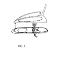
- Figure 1 shows an example of a standard shark fin antenna unit that is positioned at the backside of the rooftop of a vehicle.
- the antennas embedded in the shark fin are restricted in dimensions and should be designed to fit in the housing.
- the antenna unit also has stringent requirements for weather protection, shock resistance and temperature rise.
- Standard dimensions for the antenna unit are: Maximum height of 50 to 55mm (external housing height of 60mm), Length of 120mm (external housing length of 140mm), Width of 40mm (external housing width of 50mm).
- a resonant quarter wave monopole antenna L ⁇ 4 is a classical antenna that is used above a rooftop of a vehicle or above a ground plane.
- the inner dimensions have implications on the number of antennas that can be integrated. It is not always feasible to integrate multiple antenna elements for the same frequency band with sufficient distance between them.
- an antenna comprising:
- This arrangement combines two antenna feed into a single structure.
- the conductor areas face each other, and where they meet, parallel arms of one pass into a slot defined in the other, thereby defining an interleaved arrangement of arms and slots.
- two open slots are defined towards the outer edges and one closed slot is defined in the middle.
- the closed slot provides isolation between the feeds
- the invention provides an antenna suitable for Intelligent Transportation Systems (ITS) that enables successful car-to-car and car-to-infrastructure communication.
- ITS Intelligent Transportation Systems
- a diversity or MIMO (Multiple Input Multiple Output) functionality is provided in a single antenna element that can for example fit in an aftermarket shark fin together with other components such as a COTS GPS module and/or cellular antennas.
- the antenna provides the replacement of two physically separated antennas by a single antenna in one physical position.
- the antenna can be placed in other positions with restricted space, such as in the side mirrors.
- the antenna is of particular interest for diversity or MIMO functionality for car-to-car communication, ITS-G5A and ITS-G5B (5.855 - 5.925GHz) and ITS-G5C (5.470 - 5.725GHz).
- the antenna can be mounted in a compact area like for example in a mirror or shark fin where
- the compact and highly integrated diversity antenna consists of a single antenna structure (with two conductor areas) with two feeding ports that are sufficiently matched and isolated.
- the antenna can be implemented with and without a ground plane and for example provides 10dB diversity gain.
- the antenna preferably has a bottom edge and a top edge, which comprise the one end and the other end.
- the antenna can then be grounded at one end to a horizontal conducting plane.
- the feeds can be for a frequency band within the range 4.95-6.0GHz, for example it can be designed for an operational frequency of 5.9GHz.
- Each arm preferably has a length in the range 4mm to 7mm, for an operational frequency of 5.9GHz. This means that slots of corresponding length are formed, and this corresponding length represents a quarter electrical wavelength at the operational frequency.
- the first conductor area can comprise a rectangular part at the one end of the substrate from one edge of which the two first conductor area arms extend.
- the first conductor area can have an overall length of the rectangular part and the first conductor area arms, in the first direction, of 14 to 18mm. This corresponds to a half electrical wavelength at the operational frequency.
- the substrate preferably has a generally rectangular shape with width less than 15mm and length less than 30mm.
- the invention provides an antenna which has two feed ports and two conductor areas. Where the two areas face each other, there is a set of interdigitated arms and slots. These define a shape with two open slots (one on each side) extending from the two feed points, and a central closed slot.
- Figure 2 shows the diversity antenna 10.
- the antenna consists of a conducting surface that is connected in one example to a ground plane 12.
- the conducting surface can be planar.
- the antenna element can operate above a ground plane, like a roof top of a car or can also operate without a ground plane.
- the conducting surface is attached to a planar substrate 14.
- the substrate can be a printed circuit board material such as FR4 or any dielectric material that has sufficient performance for the frequency bands of operation.
- the choice of substrate can be kept low cost and the fabrication can be kept very low cost since existing technologies for printed circuit boards can be used.
- the conducting surface can be copper or another material that has sufficient performance for the frequency bands of operation.
- the conducting surface can be very thin, for example 35 ⁇ m.
- the conducting surface can be covered by a protecting layer to prevent oxidation and to reduce degradation due to temperature and as such to fulfill the stringent automotive requirements.
- the antenna 10 has a conducting surface on one side of the substrate making it a low cost concept in terms of manufacturing.
- the conducting surface is connected to the ground plane 12 at the bottom by a holder fixing the antenna element. In this way the conductive surface can be considered as an extension of the ground plane.
- the conducting surface contains two sub-surfaces 16 and 18. Each of these sub-surfaces comprises a main rectangular body 16a, 18a body and a slot arrangement 16b, 18b.
- a slot is defined as a non conductive area inside a conductive surface.
- the first sub-surface 16 has a single slot 16b set back into one face.
- the second sub-surface 18 has a projection 18c which extends into the single slot 16b.
- This projection 18c has a single slot 18b set back into the end face.
- the interface between the two sub-surfaces 16,18 thus comprises two outer limbs 16c of the first sub-surface 16. Between these limbs are two inner limbs 18d of the second sub-surface 18. Between these inner limbs 18d is a central slot. This forms an interdigitated parallel arm (or finger) arrangement, with two outer arms of the first sub-surface 16 and two inner arms of the second sub-surface 18. The arms can have the same length.
- Two feeding ports, F1 and F2 are connected between the two sub-surfaces, between the inner edge of the single slot 16b of the first sub-surface and the ends of the two inner arms 18d of the second sub-surface 18.
- the first sub-surface 16 contains an open slot S1 and an open slot S2. These are essentially the opposite lateral parts of the slot 16b.
- the second sub-surface SS2 contains a closed slot S3.
- the length of the first sub-surface 16 (including the main area and the arms) represents the half electrical wavelength of the operational frequency while the length of the open slots S1 and S2 is a quarter electrical wavelength of the operational frequency.
- the width of the first sub-surface 16 is not directly related to the wavelength and can be smaller than quarter of the wavelength.
- the width of the first sub-surface 16 does have an influence on the operational bandwidth of the antenna, a larger width results in a larger bandwidth.
- the length of the closed slot 18b (S3) in the second sub-surface 18 defines the frequency where the two feeding ports, F1 and F2, have largest isolation.
- the length of closed slot S3 is a quarter electrical wavelength of the frequency where the maximum isolation is found. This is because a quarter wavelength slot that is closed at the end presents a high input impedance at the input.
- the feeding ports F1 and F2 connected between the two sub-surfaces 16,18 generate a current around the slots S1 and S2. This current couples into first sub-surface 16, and more precisely spreads out across the length, that is half the resonant wavelength at the frequency of operation.
- slots S1 and S2 can be used to influence the input impedance of the feeding ports. This mechanism allows matching of both feeding ports.
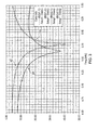
- Figure 3 shows the simulated reflection coefficients and isolation of both feeding ports (in dB) of the antenna of Figure 2 .
- Plot 30 shows the input reflection coefficient of feeding port F1 (
- Plot 32 shows the input reflection coefficient of feeding port F2 (
- Plot 34 shows the isolation between the two ports (both
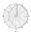
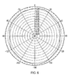
- Figures 4 to 6 show simulated radiation patterns (in dBi) of the antenna of Figure 2 in the horizontal plane at 6 GHz.
- the directivity of the radiation depends on which port is fed. For transmit diversity, both ports are fed with the same RF signal and an omnidirectional radiation pattern is established.
- Figure 7 shows the antenna structure without a ground plane. The same electrical parameters are found when analyzing this example.
- the closed slot is longer, because in the grounded situation, the slot is electrically enlarged by loading by the ground plane.
- Figure 8 shows the dimensions (in mm) of an example model of the antenna of Figure 2 that is suitable for operation in the frequency band 5.470 - 5.925GHz. This example has also been built and validated.
- the overall profile is 22mm by 10mm.
- Figure 9 shows the simulated envelope correlation coefficient of diversity antenna of Figure 2 .
- the correlation between signals received by the involved antennas at the same node of a wireless communication link is an important figure of merit of the whole system.
- the overall performance depends on the propagation behavior and antenna parameters.
- the envelope correlation coefficient is presented to evaluate the diversity capabilities of a multi-antenna system. This parameter should be preferably computed from 3D radiation patterns but this method is actually laborious and may suffer from errors if insufficient pattern cuts are taken into account in the computation.
- ⁇ 12 S 11 * ⁇ S 12 + S 12 * ⁇ S 12 2 1 - S 11 2 - S 21 2 ⁇ 1 - S 22 2 - S 12 2
- Diversity gain can be defined as the improvement in time-averaged signal-to-noise ratio (SNR) from combined signals from a diversity antenna system, relative to the SNR from one single antenna in the system, preferably the best one. This definition is conditioned by the probability that the SNR is above a reference level. The probability value is optional but usually set to 50% or 99% reliability.
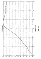
- Figure displays the simulated diversity gain of proposed diversity antenna of Figure 2 of 10dB. These results show that the antenna is very well suited for diversity or MIMO operation.
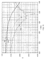
- Figure 11 displays the reflection coefficients measured at feeding port F1 and F2 (dB) on a practical model constructed according Figure 2 .
- Plot 110
- Plot 112
- Plots 114,116
- the Return Loss (S11) of the antenna meets the specification of minimum 9.5dB (VSWR 2) at the frequencies of interest and the Isolation (S21) between the integrated structures is more than 10dB at the frequencies of interest.
- signals are received at the two feeds independently, and combined during processing.
- the processing can be for example a proprietary algorithm or phase diversity which is mainstream in broadcast systems.
- both antennas can be driven by the same transmitter output signal to modify the covering range and increase radiated power.
- Another use case is when transmit diversity is used to generate multipath signals like in a MIMO application. The frequency of both signals is the same but there is a time difference between both signals. In this way the received signal strength can be increased. In another use case two different signals can be transmitted the same time and so increasing the data throughput.
Landscapes
- Engineering & Computer Science (AREA)
- Remote Sensing (AREA)
- Waveguide Aerials (AREA)
Priority Applications (3)
| Application Number | Priority Date | Filing Date | Title |
|---|---|---|---|
| EP13168948.1A EP2806497B1 (de) | 2013-05-23 | 2013-05-23 | Fahrzeugantenne |
| US14/266,470 US9570810B2 (en) | 2013-05-23 | 2014-04-30 | Vehicle antenna |
| CN201410216112.0A CN104183906B (zh) | 2013-05-23 | 2014-05-21 | 车载天线 |
Applications Claiming Priority (1)
| Application Number | Priority Date | Filing Date | Title |
|---|---|---|---|
| EP13168948.1A EP2806497B1 (de) | 2013-05-23 | 2013-05-23 | Fahrzeugantenne |
Publications (3)
| Publication Number | Publication Date |
|---|---|
| EP2806497A1 true EP2806497A1 (de) | 2014-11-26 |
| EP2806497A9 EP2806497A9 (de) | 2015-02-11 |
| EP2806497B1 EP2806497B1 (de) | 2015-12-30 |
Family
ID=48463858
Family Applications (1)
| Application Number | Title | Priority Date | Filing Date |
|---|---|---|---|
| EP13168948.1A Active EP2806497B1 (de) | 2013-05-23 | 2013-05-23 | Fahrzeugantenne |
Country Status (3)
| Country | Link |
|---|---|
| US (1) | US9570810B2 (de) |
| EP (1) | EP2806497B1 (de) |
| CN (1) | CN104183906B (de) |
Cited By (2)
| Publication number | Priority date | Publication date | Assignee | Title |
|---|---|---|---|---|
| WO2017211536A1 (de) * | 2016-06-07 | 2017-12-14 | Audi Ag | Kraftfahrzeug mit antennenanordnung |
| EP3364499A1 (de) * | 2017-02-15 | 2018-08-22 | Nxp B.V. | Antenne |
Families Citing this family (9)
| Publication number | Priority date | Publication date | Assignee | Title |
|---|---|---|---|---|
| EP3147997A1 (de) | 2015-09-25 | 2017-03-29 | Taoglas Group Holdings | Rippenartige antennenanordnungen |
| USD803196S1 (en) | 2015-09-25 | 2017-11-21 | Taoglas Group Holdings Limited | Dual fin antenna |
| USD794615S1 (en) | 2015-09-25 | 2017-08-15 | Taoglas Group Holdings | Single fin antenna |
| EP3147999A1 (de) | 2015-09-25 | 2017-03-29 | Taoglas Group Holdings | Rippenartige antennenanordnungen |
| US10374298B2 (en) | 2016-08-15 | 2019-08-06 | Ford Global Technologies, Llc | Antenna housing |
| JP6594390B2 (ja) * | 2017-10-02 | 2019-10-23 | 株式会社Subaru | アンテナ装置 |
| KR102711795B1 (ko) | 2019-02-01 | 2024-09-30 | 주식회사 케이엠더블유 | 무선 통신 장치 |
| USD912651S1 (en) * | 2019-05-24 | 2021-03-09 | Shenzhen Antop Technology Limited | Antenna base |
| JP6712001B1 (ja) * | 2019-10-18 | 2020-06-17 | 株式会社コムテック | アンテナ装置 |
Citations (4)
| Publication number | Priority date | Publication date | Assignee | Title |
|---|---|---|---|---|
| US6342868B1 (en) * | 2000-12-30 | 2002-01-29 | Hon Hai Precision Ind. Co,. Ltd. | Stripline PCB dipole antenna |
| WO2006061218A1 (en) * | 2004-12-09 | 2006-06-15 | A3 - Advanced Automotive Antennas | Miniature antenna for a motor vehicle |
| WO2008131157A1 (en) * | 2007-04-20 | 2008-10-30 | Skycross, Inc. | Multimode antenna structure |
| GB2450786A (en) * | 2007-07-03 | 2009-01-07 | Antenova Ltd | Antenna module with adjustable beam and polarization characterisitcs |
Family Cites Families (16)
| Publication number | Priority date | Publication date | Assignee | Title |
|---|---|---|---|---|
| US5734350A (en) * | 1996-04-08 | 1998-03-31 | Xertex Technologies, Inc. | Microstrip wide band antenna |
| DE19707535A1 (de) * | 1997-02-25 | 1998-08-27 | Rothe Lutz Dr Ing Habil | Folienstrahler |
| US6160515A (en) * | 1999-06-01 | 2000-12-12 | Motorola, Inc. | Dispersive surface antenna |
| US7129902B2 (en) * | 2004-03-12 | 2006-10-31 | Centurion Wireless Technologies, Inc. | Dual slot radiator single feedpoint printed circuit board antenna |
| US7119745B2 (en) * | 2004-06-30 | 2006-10-10 | International Business Machines Corporation | Apparatus and method for constructing and packaging printed antenna devices |
| US8115686B2 (en) * | 2005-07-21 | 2012-02-14 | Fractus, S.A. | Handheld device with two antennas, and method of enhancing the isolation between the antennas |
| US7688267B2 (en) * | 2006-11-06 | 2010-03-30 | Apple Inc. | Broadband antenna with coupled feed for handheld electronic devices |
| JP2009105503A (ja) * | 2007-10-19 | 2009-05-14 | Toshiba Corp | 円偏波アンテナ装置、半導体モジュール及び無線装置 |
| US8599088B2 (en) * | 2007-12-18 | 2013-12-03 | Apple Inc. | Dual-band antenna with angled slot for portable electronic devices |
| JP2010021856A (ja) * | 2008-07-11 | 2010-01-28 | Nippon Antenna Co Ltd | アンテナ装置 |
| TWI462395B (zh) * | 2008-10-09 | 2014-11-21 | Wistron Neweb Corp | 攜帶式電子裝置及其內嵌式超寬頻天線 |
| JP5306158B2 (ja) * | 2009-12-07 | 2013-10-02 | アルプス電気株式会社 | アンテナ装置 |
| JP5487938B2 (ja) * | 2009-12-16 | 2014-05-14 | 株式会社デンソー | 車両用複合アンテナ装置 |
| DE102010003646A1 (de) * | 2010-04-06 | 2011-10-06 | Robert Bosch Gmbh | Antennenanordnung für Fahrzeuge zum Senden und Empfangen |
| WO2011163141A1 (en) * | 2010-06-21 | 2011-12-29 | Rftelligent, Inc. | Small-size printed circuit board-printed meander line inverted-f antenna for radio frequency integrated circuits |
| US9203139B2 (en) * | 2012-05-04 | 2015-12-01 | Apple Inc. | Antenna structures having slot-based parasitic elements |
-
2013
- 2013-05-23 EP EP13168948.1A patent/EP2806497B1/de active Active
-
2014
- 2014-04-30 US US14/266,470 patent/US9570810B2/en active Active
- 2014-05-21 CN CN201410216112.0A patent/CN104183906B/zh active Active
Patent Citations (4)
| Publication number | Priority date | Publication date | Assignee | Title |
|---|---|---|---|---|
| US6342868B1 (en) * | 2000-12-30 | 2002-01-29 | Hon Hai Precision Ind. Co,. Ltd. | Stripline PCB dipole antenna |
| WO2006061218A1 (en) * | 2004-12-09 | 2006-06-15 | A3 - Advanced Automotive Antennas | Miniature antenna for a motor vehicle |
| WO2008131157A1 (en) * | 2007-04-20 | 2008-10-30 | Skycross, Inc. | Multimode antenna structure |
| GB2450786A (en) * | 2007-07-03 | 2009-01-07 | Antenova Ltd | Antenna module with adjustable beam and polarization characterisitcs |
Cited By (4)
| Publication number | Priority date | Publication date | Assignee | Title |
|---|---|---|---|---|
| WO2017211536A1 (de) * | 2016-06-07 | 2017-12-14 | Audi Ag | Kraftfahrzeug mit antennenanordnung |
| US10270178B2 (en) | 2016-06-07 | 2019-04-23 | Audi Ag | Motor vehicle having an antenna arrangement |
| EP3364499A1 (de) * | 2017-02-15 | 2018-08-22 | Nxp B.V. | Antenne |
| US10243269B2 (en) | 2017-02-15 | 2019-03-26 | Nxp B.V. | Antenna |
Also Published As
| Publication number | Publication date |
|---|---|
| US20140347231A1 (en) | 2014-11-27 |
| CN104183906A (zh) | 2014-12-03 |
| EP2806497B1 (de) | 2015-12-30 |
| CN104183906B (zh) | 2016-08-24 |
| US9570810B2 (en) | 2017-02-14 |
| EP2806497A9 (de) | 2015-02-11 |
Similar Documents
| Publication | Publication Date | Title |
|---|---|---|
| EP2806497B1 (de) | Fahrzeugantenne | |
| US6218992B1 (en) | Compact, broadband inverted-F antennas with conductive elements and wireless communicators incorporating same | |
| US6268831B1 (en) | Inverted-f antennas with multiple planar radiating elements and wireless communicators incorporating same | |
| US6982675B2 (en) | Internal multi-band antenna with multiple layers | |
| US6906669B2 (en) | Multifunction antenna | |
| US10333208B2 (en) | Antenna device | |
| EP2602865B1 (de) | Mehrbandantenne | |
| US6229487B1 (en) | Inverted-F antennas having non-linear conductive elements and wireless communicators incorporating the same | |
| US6225951B1 (en) | Antenna systems having capacitively coupled internal and retractable antennas and wireless communicators incorporating same | |
| US10615492B2 (en) | Multi-band, shark fin antenna for V2X communications | |
| CN102655268B (zh) | 多频带天线 | |
| WO2001052353A2 (en) | Low cost compact omni-directional printed antenna | |
| WO2013093466A1 (en) | Antenna element & antenna device comprising such elements | |
| EP1459410B1 (de) | Breitbandige mehrbandantenne | |
| CN102655266B (zh) | 多频带天线 | |
| JP2009246844A (ja) | 自動車用高周波ガラスアンテナ及び自動車用の窓ガラス板 | |
| US7148848B2 (en) | Dual band, bent monopole antenna | |
| US7050011B2 (en) | Low profile antenna for remote vehicle communication system | |
| JP7835228B2 (ja) | 平面アンテナ及び車両用窓ガラス | |
| US10243269B2 (en) | Antenna | |
| US20100321274A1 (en) | Multiple frequency antenna assembly | |
| KR20090067896A (ko) | 광대역 칩 내장형 안테나 |
Legal Events
| Date | Code | Title | Description |
|---|---|---|---|
| PUAI | Public reference made under article 153(3) epc to a published international application that has entered the european phase |
Free format text: ORIGINAL CODE: 0009012 |
|
| 17P | Request for examination filed |
Effective date: 20131031 |
|
| AK | Designated contracting states |
Kind code of ref document: A1 Designated state(s): AL AT BE BG CH CY CZ DE DK EE ES FI FR GB GR HR HU IE IS IT LI LT LU LV MC MK MT NL NO PL PT RO RS SE SI SK SM TR |
|
| AX | Request for extension of the european patent |
Extension state: BA ME |
|
| GRAP | Despatch of communication of intention to grant a patent |
Free format text: ORIGINAL CODE: EPIDOSNIGR1 |
|
| INTG | Intention to grant announced |
Effective date: 20150327 |
|
| RBV | Designated contracting states (corrected) |
Designated state(s): AL AT BE BG CH CY CZ DE DK EE ES FI FR GB GR HR HU IE IS IT LI LT LU LV MC MK MT NL NO PL PT RO RS SE SI SK SM TR |
|
| GRAP | Despatch of communication of intention to grant a patent |
Free format text: ORIGINAL CODE: EPIDOSNIGR1 |
|
| INTG | Intention to grant announced |
Effective date: 20150915 |
|
| RIN1 | Information on inventor provided before grant (corrected) |
Inventor name: KERSELAERS, ANTHONY Inventor name: GOMME, LIESBETH |
|
| GRAS | Grant fee paid |
Free format text: ORIGINAL CODE: EPIDOSNIGR3 |
|
| GRAA | (expected) grant |
Free format text: ORIGINAL CODE: 0009210 |
|
| AK | Designated contracting states |
Kind code of ref document: B1 Designated state(s): AL AT BE BG CH CY CZ DE DK EE ES FI FR GB GR HR HU IE IS IT LI LT LU LV MC MK MT NL NO PL PT RO RS SE SI SK SM TR |
|
| REG | Reference to a national code |
Ref country code: GB Ref legal event code: FG4D |
|
| REG | Reference to a national code |
Ref country code: CH Ref legal event code: EP |
|
| REG | Reference to a national code |
Ref country code: AT Ref legal event code: REF Ref document number: 767846 Country of ref document: AT Kind code of ref document: T Effective date: 20160115 |
|
| REG | Reference to a national code |
Ref country code: IE Ref legal event code: FG4D |
|
| REG | Reference to a national code |
Ref country code: DE Ref legal event code: R096 Ref document number: 602013004305 Country of ref document: DE |
|
| REG | Reference to a national code |
Ref country code: FR Ref legal event code: PLFP Year of fee payment: 4 |
|
| REG | Reference to a national code |
Ref country code: LT Ref legal event code: MG4D |
|
| PG25 | Lapsed in a contracting state [announced via postgrant information from national office to epo] |
Ref country code: NO Free format text: LAPSE BECAUSE OF FAILURE TO SUBMIT A TRANSLATION OF THE DESCRIPTION OR TO PAY THE FEE WITHIN THE PRESCRIBED TIME-LIMIT Effective date: 20160330 Ref country code: LT Free format text: LAPSE BECAUSE OF FAILURE TO SUBMIT A TRANSLATION OF THE DESCRIPTION OR TO PAY THE FEE WITHIN THE PRESCRIBED TIME-LIMIT Effective date: 20151230 Ref country code: HR Free format text: LAPSE BECAUSE OF FAILURE TO SUBMIT A TRANSLATION OF THE DESCRIPTION OR TO PAY THE FEE WITHIN THE PRESCRIBED TIME-LIMIT Effective date: 20151230 |
|
| REG | Reference to a national code |
Ref country code: NL Ref legal event code: MP Effective date: 20151230 |
|
| REG | Reference to a national code |
Ref country code: AT Ref legal event code: MK05 Ref document number: 767846 Country of ref document: AT Kind code of ref document: T Effective date: 20151230 |
|
| PG25 | Lapsed in a contracting state [announced via postgrant information from national office to epo] |
Ref country code: SE Free format text: LAPSE BECAUSE OF FAILURE TO SUBMIT A TRANSLATION OF THE DESCRIPTION OR TO PAY THE FEE WITHIN THE PRESCRIBED TIME-LIMIT Effective date: 20151230 Ref country code: GR Free format text: LAPSE BECAUSE OF FAILURE TO SUBMIT A TRANSLATION OF THE DESCRIPTION OR TO PAY THE FEE WITHIN THE PRESCRIBED TIME-LIMIT Effective date: 20160331 Ref country code: LV Free format text: LAPSE BECAUSE OF FAILURE TO SUBMIT A TRANSLATION OF THE DESCRIPTION OR TO PAY THE FEE WITHIN THE PRESCRIBED TIME-LIMIT Effective date: 20151230 Ref country code: RS Free format text: LAPSE BECAUSE OF FAILURE TO SUBMIT A TRANSLATION OF THE DESCRIPTION OR TO PAY THE FEE WITHIN THE PRESCRIBED TIME-LIMIT Effective date: 20151230 Ref country code: FI Free format text: LAPSE BECAUSE OF FAILURE TO SUBMIT A TRANSLATION OF THE DESCRIPTION OR TO PAY THE FEE WITHIN THE PRESCRIBED TIME-LIMIT Effective date: 20151230 |
|
| PG25 | Lapsed in a contracting state [announced via postgrant information from national office to epo] |
Ref country code: NL Free format text: LAPSE BECAUSE OF FAILURE TO SUBMIT A TRANSLATION OF THE DESCRIPTION OR TO PAY THE FEE WITHIN THE PRESCRIBED TIME-LIMIT Effective date: 20151230 |
|
| PG25 | Lapsed in a contracting state [announced via postgrant information from national office to epo] |
Ref country code: ES Free format text: LAPSE BECAUSE OF FAILURE TO SUBMIT A TRANSLATION OF THE DESCRIPTION OR TO PAY THE FEE WITHIN THE PRESCRIBED TIME-LIMIT Effective date: 20151230 Ref country code: CZ Free format text: LAPSE BECAUSE OF FAILURE TO SUBMIT A TRANSLATION OF THE DESCRIPTION OR TO PAY THE FEE WITHIN THE PRESCRIBED TIME-LIMIT Effective date: 20151230 Ref country code: IT Free format text: LAPSE BECAUSE OF FAILURE TO SUBMIT A TRANSLATION OF THE DESCRIPTION OR TO PAY THE FEE WITHIN THE PRESCRIBED TIME-LIMIT Effective date: 20151230 |
|
| PG25 | Lapsed in a contracting state [announced via postgrant information from national office to epo] |
Ref country code: RO Free format text: LAPSE BECAUSE OF FAILURE TO SUBMIT A TRANSLATION OF THE DESCRIPTION OR TO PAY THE FEE WITHIN THE PRESCRIBED TIME-LIMIT Effective date: 20151230 Ref country code: IS Free format text: LAPSE BECAUSE OF FAILURE TO SUBMIT A TRANSLATION OF THE DESCRIPTION OR TO PAY THE FEE WITHIN THE PRESCRIBED TIME-LIMIT Effective date: 20160430 Ref country code: PT Free format text: LAPSE BECAUSE OF FAILURE TO SUBMIT A TRANSLATION OF THE DESCRIPTION OR TO PAY THE FEE WITHIN THE PRESCRIBED TIME-LIMIT Effective date: 20160502 Ref country code: AT Free format text: LAPSE BECAUSE OF FAILURE TO SUBMIT A TRANSLATION OF THE DESCRIPTION OR TO PAY THE FEE WITHIN THE PRESCRIBED TIME-LIMIT Effective date: 20151230 Ref country code: EE Free format text: LAPSE BECAUSE OF FAILURE TO SUBMIT A TRANSLATION OF THE DESCRIPTION OR TO PAY THE FEE WITHIN THE PRESCRIBED TIME-LIMIT Effective date: 20151230 Ref country code: SM Free format text: LAPSE BECAUSE OF FAILURE TO SUBMIT A TRANSLATION OF THE DESCRIPTION OR TO PAY THE FEE WITHIN THE PRESCRIBED TIME-LIMIT Effective date: 20151230 Ref country code: PL Free format text: LAPSE BECAUSE OF FAILURE TO SUBMIT A TRANSLATION OF THE DESCRIPTION OR TO PAY THE FEE WITHIN THE PRESCRIBED TIME-LIMIT Effective date: 20151230 Ref country code: SK Free format text: LAPSE BECAUSE OF FAILURE TO SUBMIT A TRANSLATION OF THE DESCRIPTION OR TO PAY THE FEE WITHIN THE PRESCRIBED TIME-LIMIT Effective date: 20151230 Ref country code: BE Free format text: LAPSE BECAUSE OF NON-PAYMENT OF DUE FEES Effective date: 20160531 |
|
| REG | Reference to a national code |
Ref country code: DE Ref legal event code: R097 Ref document number: 602013004305 Country of ref document: DE |
|
| PG25 | Lapsed in a contracting state [announced via postgrant information from national office to epo] |
Ref country code: DK Free format text: LAPSE BECAUSE OF FAILURE TO SUBMIT A TRANSLATION OF THE DESCRIPTION OR TO PAY THE FEE WITHIN THE PRESCRIBED TIME-LIMIT Effective date: 20151230 |
|
| PLBE | No opposition filed within time limit |
Free format text: ORIGINAL CODE: 0009261 |
|
| STAA | Information on the status of an ep patent application or granted ep patent |
Free format text: STATUS: NO OPPOSITION FILED WITHIN TIME LIMIT |
|
| 26N | No opposition filed |
Effective date: 20161003 |
|
| PG25 | Lapsed in a contracting state [announced via postgrant information from national office to epo] |
Ref country code: BE Free format text: LAPSE BECAUSE OF FAILURE TO SUBMIT A TRANSLATION OF THE DESCRIPTION OR TO PAY THE FEE WITHIN THE PRESCRIBED TIME-LIMIT Effective date: 20151230 Ref country code: LU Free format text: LAPSE BECAUSE OF FAILURE TO SUBMIT A TRANSLATION OF THE DESCRIPTION OR TO PAY THE FEE WITHIN THE PRESCRIBED TIME-LIMIT Effective date: 20160523 |
|
| REG | Reference to a national code |
Ref country code: CH Ref legal event code: PL |
|
| PG25 | Lapsed in a contracting state [announced via postgrant information from national office to epo] |
Ref country code: LI Free format text: LAPSE BECAUSE OF NON-PAYMENT OF DUE FEES Effective date: 20160531 Ref country code: CH Free format text: LAPSE BECAUSE OF NON-PAYMENT OF DUE FEES Effective date: 20160531 |
|
| REG | Reference to a national code |
Ref country code: IE Ref legal event code: MM4A |
|
| PG25 | Lapsed in a contracting state [announced via postgrant information from national office to epo] |
Ref country code: SI Free format text: LAPSE BECAUSE OF FAILURE TO SUBMIT A TRANSLATION OF THE DESCRIPTION OR TO PAY THE FEE WITHIN THE PRESCRIBED TIME-LIMIT Effective date: 20151230 |
|
| REG | Reference to a national code |
Ref country code: FR Ref legal event code: PLFP Year of fee payment: 5 |
|
| PG25 | Lapsed in a contracting state [announced via postgrant information from national office to epo] |
Ref country code: IE Free format text: LAPSE BECAUSE OF NON-PAYMENT OF DUE FEES Effective date: 20160523 |
|
| REG | Reference to a national code |
Ref country code: FR Ref legal event code: PLFP Year of fee payment: 6 |
|
| PG25 | Lapsed in a contracting state [announced via postgrant information from national office to epo] |
Ref country code: HU Free format text: LAPSE BECAUSE OF FAILURE TO SUBMIT A TRANSLATION OF THE DESCRIPTION OR TO PAY THE FEE WITHIN THE PRESCRIBED TIME-LIMIT; INVALID AB INITIO Effective date: 20130523 |
|
| PG25 | Lapsed in a contracting state [announced via postgrant information from national office to epo] |
Ref country code: MC Free format text: LAPSE BECAUSE OF FAILURE TO SUBMIT A TRANSLATION OF THE DESCRIPTION OR TO PAY THE FEE WITHIN THE PRESCRIBED TIME-LIMIT Effective date: 20151230 Ref country code: MT Free format text: LAPSE BECAUSE OF NON-PAYMENT OF DUE FEES Effective date: 20160531 Ref country code: CY Free format text: LAPSE BECAUSE OF FAILURE TO SUBMIT A TRANSLATION OF THE DESCRIPTION OR TO PAY THE FEE WITHIN THE PRESCRIBED TIME-LIMIT Effective date: 20151230 Ref country code: MK Free format text: LAPSE BECAUSE OF FAILURE TO SUBMIT A TRANSLATION OF THE DESCRIPTION OR TO PAY THE FEE WITHIN THE PRESCRIBED TIME-LIMIT Effective date: 20151230 |
|
| PG25 | Lapsed in a contracting state [announced via postgrant information from national office to epo] |
Ref country code: BG Free format text: LAPSE BECAUSE OF FAILURE TO SUBMIT A TRANSLATION OF THE DESCRIPTION OR TO PAY THE FEE WITHIN THE PRESCRIBED TIME-LIMIT Effective date: 20151230 |
|
| PG25 | Lapsed in a contracting state [announced via postgrant information from national office to epo] |
Ref country code: AL Free format text: LAPSE BECAUSE OF FAILURE TO SUBMIT A TRANSLATION OF THE DESCRIPTION OR TO PAY THE FEE WITHIN THE PRESCRIBED TIME-LIMIT Effective date: 20151230 Ref country code: TR Free format text: LAPSE BECAUSE OF FAILURE TO SUBMIT A TRANSLATION OF THE DESCRIPTION OR TO PAY THE FEE WITHIN THE PRESCRIBED TIME-LIMIT Effective date: 20151230 |
|
| P01 | Opt-out of the competence of the unified patent court (upc) registered |
Effective date: 20230725 |
|
| PGFP | Annual fee paid to national office [announced via postgrant information from national office to epo] |
Ref country code: DE Payment date: 20250423 Year of fee payment: 13 |
|
| PGFP | Annual fee paid to national office [announced via postgrant information from national office to epo] |
Ref country code: GB Payment date: 20250423 Year of fee payment: 13 |
|
| PGFP | Annual fee paid to national office [announced via postgrant information from national office to epo] |
Ref country code: FR Payment date: 20250424 Year of fee payment: 13 |