EP2806490B1 - Temperaturregelung für Brennstoffzellen - Google Patents
Temperaturregelung für Brennstoffzellen Download PDFInfo
- Publication number
- EP2806490B1 EP2806490B1 EP13150929.1A EP13150929A EP2806490B1 EP 2806490 B1 EP2806490 B1 EP 2806490B1 EP 13150929 A EP13150929 A EP 13150929A EP 2806490 B1 EP2806490 B1 EP 2806490B1
- Authority
- EP
- European Patent Office
- Prior art keywords
- temperature
- stack
- air
- fuel cell
- process model
- Prior art date
- Legal status (The legal status is an assumption and is not a legal conclusion. Google has not performed a legal analysis and makes no representation as to the accuracy of the status listed.)
- Not-in-force
Links
- 239000000446 fuel Substances 0.000 title claims description 26
- 238000000034 method Methods 0.000 claims description 56
- 239000002737 fuel gas Substances 0.000 description 8
- 238000011161 development Methods 0.000 description 5
- 238000001816 cooling Methods 0.000 description 3
- 239000007789 gas Substances 0.000 description 3
- 238000005259 measurement Methods 0.000 description 3
- 230000001276 controlling effect Effects 0.000 description 2
- 238000010586 diagram Methods 0.000 description 2
- 230000000694 effects Effects 0.000 description 2
- 239000003792 electrolyte Substances 0.000 description 2
- 238000009434 installation Methods 0.000 description 2
- 238000012935 Averaging Methods 0.000 description 1
- 230000006978 adaptation Effects 0.000 description 1
- 238000009529 body temperature measurement Methods 0.000 description 1
- 230000015556 catabolic process Effects 0.000 description 1
- 238000006731 degradation reaction Methods 0.000 description 1
- 238000001514 detection method Methods 0.000 description 1
- 238000001035 drying Methods 0.000 description 1
- 230000005611 electricity Effects 0.000 description 1
- 238000005342 ion exchange Methods 0.000 description 1
- 230000007774 longterm Effects 0.000 description 1
- 230000000704 physical effect Effects 0.000 description 1
- 229920005597 polymer membrane Polymers 0.000 description 1
- 230000001105 regulatory effect Effects 0.000 description 1
- 238000004088 simulation Methods 0.000 description 1
- 230000001052 transient effect Effects 0.000 description 1
- 239000002918 waste heat Substances 0.000 description 1
Images

Classifications
-
- H—ELECTRICITY
- H01—ELECTRIC ELEMENTS
- H01M—PROCESSES OR MEANS, e.g. BATTERIES, FOR THE DIRECT CONVERSION OF CHEMICAL ENERGY INTO ELECTRICAL ENERGY
- H01M8/00—Fuel cells; Manufacture thereof
- H01M8/04—Auxiliary arrangements, e.g. for control of pressure or for circulation of fluids
- H01M8/04298—Processes for controlling fuel cells or fuel cell systems
- H01M8/04313—Processes for controlling fuel cells or fuel cell systems characterised by the detection or assessment of variables; characterised by the detection or assessment of failure or abnormal function
- H01M8/04537—Electric variables
- H01M8/04574—Current
- H01M8/04589—Current of fuel cell stacks
-
- H—ELECTRICITY
- H01—ELECTRIC ELEMENTS
- H01M—PROCESSES OR MEANS, e.g. BATTERIES, FOR THE DIRECT CONVERSION OF CHEMICAL ENERGY INTO ELECTRICAL ENERGY
- H01M8/00—Fuel cells; Manufacture thereof
- H01M8/04—Auxiliary arrangements, e.g. for control of pressure or for circulation of fluids
- H01M8/04298—Processes for controlling fuel cells or fuel cell systems
- H01M8/04313—Processes for controlling fuel cells or fuel cell systems characterised by the detection or assessment of variables; characterised by the detection or assessment of failure or abnormal function
- H01M8/0432—Temperature; Ambient temperature
- H01M8/04335—Temperature; Ambient temperature of cathode reactants at the inlet or inside the fuel cell
-
- H—ELECTRICITY
- H01—ELECTRIC ELEMENTS
- H01M—PROCESSES OR MEANS, e.g. BATTERIES, FOR THE DIRECT CONVERSION OF CHEMICAL ENERGY INTO ELECTRICAL ENERGY
- H01M8/00—Fuel cells; Manufacture thereof
- H01M8/04—Auxiliary arrangements, e.g. for control of pressure or for circulation of fluids
- H01M8/04298—Processes for controlling fuel cells or fuel cell systems
- H01M8/04313—Processes for controlling fuel cells or fuel cell systems characterised by the detection or assessment of variables; characterised by the detection or assessment of failure or abnormal function
- H01M8/0432—Temperature; Ambient temperature
- H01M8/0435—Temperature; Ambient temperature of cathode exhausts
-
- H—ELECTRICITY
- H01—ELECTRIC ELEMENTS
- H01M—PROCESSES OR MEANS, e.g. BATTERIES, FOR THE DIRECT CONVERSION OF CHEMICAL ENERGY INTO ELECTRICAL ENERGY
- H01M8/00—Fuel cells; Manufacture thereof
- H01M8/04—Auxiliary arrangements, e.g. for control of pressure or for circulation of fluids
- H01M8/04298—Processes for controlling fuel cells or fuel cell systems
- H01M8/04694—Processes for controlling fuel cells or fuel cell systems characterised by variables to be controlled
- H01M8/04701—Temperature
-
- H—ELECTRICITY
- H01—ELECTRIC ELEMENTS
- H01M—PROCESSES OR MEANS, e.g. BATTERIES, FOR THE DIRECT CONVERSION OF CHEMICAL ENERGY INTO ELECTRICAL ENERGY
- H01M8/00—Fuel cells; Manufacture thereof
- H01M8/04—Auxiliary arrangements, e.g. for control of pressure or for circulation of fluids
- H01M8/04298—Processes for controlling fuel cells or fuel cell systems
- H01M8/04694—Processes for controlling fuel cells or fuel cell systems characterised by variables to be controlled
- H01M8/04746—Pressure; Flow
- H01M8/04753—Pressure; Flow of fuel cell reactants
-
- H—ELECTRICITY
- H01—ELECTRIC ELEMENTS
- H01M—PROCESSES OR MEANS, e.g. BATTERIES, FOR THE DIRECT CONVERSION OF CHEMICAL ENERGY INTO ELECTRICAL ENERGY
- H01M8/00—Fuel cells; Manufacture thereof
- H01M8/04—Auxiliary arrangements, e.g. for control of pressure or for circulation of fluids
- H01M8/04298—Processes for controlling fuel cells or fuel cell systems
- H01M8/04694—Processes for controlling fuel cells or fuel cell systems characterised by variables to be controlled
- H01M8/04858—Electric variables
- H01M8/04895—Current
- H01M8/0491—Current of fuel cell stacks
-
- H—ELECTRICITY
- H01—ELECTRIC ELEMENTS
- H01M—PROCESSES OR MEANS, e.g. BATTERIES, FOR THE DIRECT CONVERSION OF CHEMICAL ENERGY INTO ELECTRICAL ENERGY
- H01M8/00—Fuel cells; Manufacture thereof
- H01M8/10—Fuel cells with solid electrolytes
- H01M8/12—Fuel cells with solid electrolytes operating at high temperature, e.g. with stabilised ZrO2 electrolyte
- H01M2008/1293—Fuel cells with solid oxide electrolytes
-
- Y—GENERAL TAGGING OF NEW TECHNOLOGICAL DEVELOPMENTS; GENERAL TAGGING OF CROSS-SECTIONAL TECHNOLOGIES SPANNING OVER SEVERAL SECTIONS OF THE IPC; TECHNICAL SUBJECTS COVERED BY FORMER USPC CROSS-REFERENCE ART COLLECTIONS [XRACs] AND DIGESTS
- Y02—TECHNOLOGIES OR APPLICATIONS FOR MITIGATION OR ADAPTATION AGAINST CLIMATE CHANGE
- Y02E—REDUCTION OF GREENHOUSE GAS [GHG] EMISSIONS, RELATED TO ENERGY GENERATION, TRANSMISSION OR DISTRIBUTION
- Y02E60/00—Enabling technologies; Technologies with a potential or indirect contribution to GHG emissions mitigation
- Y02E60/30—Hydrogen technology
- Y02E60/50—Fuel cells
Definitions
- the invention relates to a method for regulating the temperature of the stack of a fuel cell, preferably an SOFC fuel cell.
- a temperature on the exit side or in the stack core is used as the controlled variable.
- the use of the temperature at the exit side involves the problem that the temperature measured there reflects the temperature inside the stack only with a time delay.
- controllers for systems subject to dead time are known, instability can nevertheless occur in the control of the stack temperature since the dead time of the system depends on further parameters.
- thermocouples The direct measurement of the temperature in the stack involves the problem that in the case of SOFC stacks, access to the stack core is only possible via the gas chambers or optionally via special installations. If you choose the access through the gas chambers, you have little space available, so that you can use only very thin thermocouples with a very limited life. Furthermore, even very thin thermocouples can influence the flow conditions in the stack.
- special installations such as For example, intermediate plates are also difficult to implement and affect the stack by changing the thermal conductivity, additional interface, etc.
- a fuel cell system and a method for influencing the heat and temperature balance of a fuel cell stack in a fuel cell system will be described.
- the temperature of the cathode supply air and the cathode exhaust air in front of and behind the stack is measured with temperature sensors.
- Two control circuits are used.
- the first control circuit is based on the temperature measured by the temperature sensor for the cathode feed air and uses the setting of a volume flow divider as a manipulated variable.
- the second control circuit is based on the temperature measured by the temperature sensor for the cathode exhaust air and used as a manipulated variable, the speed of the cathode exhaust air blower.
- the object is achieved in that the direct measurement of the temperature inside the stack is replaced by a detection of the electric current and an estimate of how the temperature inside the stack due to the power loss with respect to the temperature of the stack at the air inlet and / or air outlet behaves.
- This is done on the basis of a process model.
- This makes it possible to regulate the temperature inside the stack indirectly by controlling a temperature characteristic calculated from weighted temperatures of the stack at the air inlet and / or outlet.
- the process model can be present, for example, in the form of a parameter equation or a table and represents the desired value of the temperature characteristic as a function of the current. Such a relationship is basically known from the patent specification US 3,595,699 and can be determined in advance by measurements or simulations.
- the main influencing factors here are the thermal conductivity of the stack and the division between convective and radiant cooling, etc.
- the temperature is determined which must prevail at the air inlet and outlet of the stack, so that the temperature inside the stack corresponds to the desired value.
- the amount of heat which is determined by the temperature of the supplied air and / or the air volume flow, then the temperature of the stack is adjusted accordingly. It is also taken into account in the process model that a higher air flow rate also dissipates a larger amount of heat from the stack.
- the amount of heat is influenced by the temperature of the air. This is preferably done by mixing two air streams with different temperature, such as fresh air and preheated by waste heat of the fuel cell air.
- this is done by the mass flow of the supplied air.
- the temperature characteristic value is calculated in a method variant from the first factor-weighted temperature of the stack at the air inlet and the second factor-weighted temperature of the stack at the air outlet.
- averaging is performed. If the first factor is greater than the second factor, the temperature of the stack at the air inlet is considered more.
- the temperature of the stack at the air outlet is not taken into account, this means that the temperature characteristic is formed only from the temperature of the stack at the air inlet.
- the supplied current of the fuel cell is adapted to the requested current only when the temperature at the air inlet of the stack is reached.
- the current is adapted directly to the respective power requirement.
- the regulation of the temperature takes place in parallel. This is particularly advantageous when the current is changed in ramps. When exceeding a certain temperature difference, however, a further change in current can be suspended.
- the dynamics of the temperature change are taken into account. Since the stack has a mass and a heat capacity, the temperature will increase gradually as the current increases. This fact is taken into account in the dynamic process model in the further development of the method.
- the temperature is additionally measured at the air outlet of the stack and compared with the expected temperature based on the process model. If it is determined that the temperature at the air outlet of the stack deviates, which indicates an error of the process model, the process model is corrected. This can be the case, for example, in the case of a degradation of the stack, in which the physical properties of the stack change and thus no longer match the process model.
- the first and the second factor, with which the temperature of the stack at the air inlet and the air outlet are weighted, and the process model are coordinated so that the amount of heat stored in the stack regardless of the current and so that it is constant regardless of the load condition. This is the case when both factors are equal. If they take the value 0.5, an average temperature is formed. This ensures that the temperature inside the stack is constant. If the first factor is chosen larger, this leads to a stronger weighting of the temperature on Air inlet of the stack. This development is advantageous in transient operating conditions.
- a fuel cell according to the invention on which the method is carried out, has a stack, a temperature sensor, a fan for supplying air and a regulator.
- the controller carries out the method steps described above.
- a temperature sensor is provided at the air outlet of the stack, with the aid of which the process model can be corrected in the controller and the temperature weighted with the temperature of the stack at the air inlet can be calculated to a temperature characteristic.
- FIG. 1 shows the stack of a fuel cell according to the invention.
- the stack consists of several stacked plates 2, which are separated by an intermediate layer 3.
- the intermediate layer 3 consists of an anode 4 facing the fuel gas, an electrolyte 5 and a cathode 6 facing the air. Due to this structure, an ion exchange takes place, whereby electric energy is generated.
- the air flows from the air supply 7 to the air discharge 8 and the fuel gas crosswise from the fuel gas supply 9 to the fuel gas discharge 10.
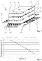
- FIG. 2 It is shown how the set point of the temperature characteristic, which is weighted from the temperature of the stack at the air inlet and outlet, depending on the current, so that a desired temperature is reached inside the stack.
- FIG. 3 shows the circuit diagram of a detail of a fuel cell according to the invention.
- Cold fresh air is mixed with preheated air from a mixer 23 via a supply for fresh air 22 and a supply for preheated air 21 and fed via the blower 15 to the air inlet 12 of the stack 1.
- the mixer 23 is arranged behind the blower 15, wherein the blower is provided in two or only in one of the supply lines 21, 22. In the case that in both supply lines 21, 22 a blower 15 is provided, the mixer 23 can be replaced by a corresponding control of the two fans.
- This current is controlled by a current regulator 17 according to a requested current.
- a temperature sensor 11 is provided at the air inlet 12 of the stack 1.
- a temperature sensor 14 is also provided at the air outlet 13 of the stack 1.
- the temperature sensors 11, 14 detect the stack temperature at the air inlet and air outlet.
- a computing element 19 weights the two measured temperatures of the sensors 11, 14 and provides a temperature characteristic value 20.
- This temperature characteristic value 20 is fed to a controller 16, which regulates the temperature characteristic value 20 to a predetermined desired value 24.
- This predetermined desired value 24 is determined on the basis of a process model 25 from the requested current of the stack, which is provided by the current regulator 17.
- the process model 25 may be in the form of a parameter equation, a table or in the form of a dynamic process model and establishes a relationship between the current and the setpoint of the temperature characteristic.
- the temperature controller 16 outputs a signal to the blower 15 and / or the mixer 23. Instead of the control of the fan 15, for example, air dampers or a throttle could be controlled.
- the temperature controller 16, the current controller 17, the computing element 19 and the process model 24 are combined in a controller 18.
- the current regulator 17 may be operated to either adjust the current continuously and in parallel with the regulation of the temperature by the temperature regulator 16. Alternatively, the current regulator 17 can be operated such that the requested current is not supplied by the stack 1 until the temperature characteristic value 20 has approached the desired value. It is also possible to use the aforementioned continuous adaptation of the current so that the requested current is not supplied by the stack 1 until the deviation of the temperature characteristic 20 from the target value is within a safe range. As a result, overloads can be avoided.
- the controller 18 can also monitor the process model continuously by comparing the measured value of the temperature sensor 14 with an expected measured value. This temperature correlates very well with the temperature inside the stack 1, but can not be used directly for a stable temperature control due to the time delay. The temperature measured by the temperature sensor 14 is compared with the temperature expected inside the stack. In the case of long-term deviations, the parameters of the process model stored in the temperature controller 16 are corrected.
- the method of control proceeds as follows. It is assumed that the fuel cell is in a stationary state. Upon a change in the requested current affecting the current regulator 17, the requested current is first passed to the process model 24. This determines the appropriate setpoint of the temperature parameter. The temperature is then measured by means of the temperature sensors 11 and 14 and added by the computing element 19 in a weighted manner.
- the weighting may, for example, be such that the value of the temperature sensor 11 is multiplied by a first factor 0.5 and the value of the temperature sensor 14 by a second factor 0.5. Subsequently, both products are added. Other weights such as 1.0 for the first factor and 0 for the second factor and other weights are also possible. Which weighting is advantageous depends on the dynamic properties of the stack and the quality of the control to be achieved.
- the formed temperature characteristic 20 is compared with the desired value.
- the effect on the fan 15 and / or the mixer 23 is that the air quantity is increased and / or the temperature of the air is reduced if the temperature characteristic value is too high.
- the temperature controller releases the requested current to the current controller 17, which now increases the current.
Landscapes
- Life Sciences & Earth Sciences (AREA)
- Engineering & Computer Science (AREA)
- Manufacturing & Machinery (AREA)
- Sustainable Development (AREA)
- Sustainable Energy (AREA)
- Chemical & Material Sciences (AREA)
- Chemical Kinetics & Catalysis (AREA)
- Electrochemistry (AREA)
- General Chemical & Material Sciences (AREA)
- Fuel Cell (AREA)
Description
- Die Erfindung betrifft ein Verfahren zur Regelung der Temperatur des Stacks einer Brennstoffzelle, bevorzugt einer SOFC-Brennstoffzelle.
- Zur gattungsgemäßen Stacktemperaturregelung wird eine Temperatur auf der Austrittsseite oder im Stackkern als Regelgröße herangezogen.
- Die Verwendung der Temperatur an der Austrittsseite bringt das Problem mit sich, dass die dort gemessene Temperatur die Temperatur im Inneren des Stacks nur mit einer Zeitverzögerung wiedergibt. Es sind zwar Regler für Totzeit behaftete Systeme bekannt, jedoch kann es bei der Regelung der Stacktemperatur dennoch zu Instabilitäten kommen, da die Totzeit des Systems von weiteren Parametern abhängig ist.
- Die direkte Messung der Temperatur im Stack bringt das Problem mit sich, dass bei SOFC-Stacks der Zugang zum Stackkern nur über die Gasräume oder gegebenenfalls über Sondereinbauten möglich ist. Wählt man den Zugang über die Gasräume, hat man nur wenig Bauraum zur Verfügung, so dass man nur sehr dünne Thermoelemente mit sehr begrenzter Lebensdauer verwenden kann. Weiterhin können selbst sehr dünne Thermoelemente die Strömungsverhältnisse im Stack beeinflussen. Die Verwendung von Sondereinbauten wie z.B. Zwischenplatten sind ebenfalls schwer realisierbar und beeinflussen den Stack durch eine veränderte Wärmeleitfähigkeit, zusätzliche Grenzfläche usw.
- In der Patenanmeldung
WO 2008/028441 A2 wird ein Brennstoffzellensystem sowie ein Verfahren zum Beeinflussen des Wärme-und Temperaturhaushalts eines Brennstoffzellenstapels in einem Brennstoffzellensystem beschrieben. Dazu wird mit Temperatursensoren die Temperatur der Katodenzuluft und der Kathodenabluft vor und hinter dem Stack gemessen. Dabei werden 2 Regelkreise eingesetzt. Der erste Regelkreis beruht auf der vom Temperatursensor für die Kathodenzuluft gemessenen Temperatur und verwendet als Stellgröße die Einstellung eines Volumenstromteilers. Der zweite Regelkreis beruht auf der vom Temperatursensor für die Kathodenabluft gemessenen Temperatur und verwendet als Stellgröße die Drehzahl des Kathodenabluft Gebläses. Alternativ wird vorgeschlagen, die Drehzahl des Kathodenabluft Gebläses in Abhängigkeit der Temperaturdifferenzen zwischen Katode zu Luft und Kathodenabluft zu regeln. Da die Temperaturmessung außerhalb des Stacks erfolgt, repräsentieren die Messwerte nicht die Stacktemperatur. - Das Patent
US 3,595,699 offenbart ein Regelungssystems für Brennstoffzellen, bei dem die Verlustwärme anhand der Brennstoffzellenbelastung vorher gesehen wird, so dass die Kühlung ohne zeitliche Verzögerung erfolgen kann. - Die Patentanmeldung
US 2002/0006537 A1 beschreibt die Gaszufuhr an einem Brennstoffzellensystem. - Die Patentanmeldung
US 2011/0311889 A1 offenbart ein Brennstoffzellensystem mit einer Kühlung, bei dem die Eintrocknung der Polymermembran überwacht wird. - Es ist daher Aufgabe der Erfindung, ein Verfahren zur Regelung der Temperatur im Inneren des Stacks sowie eine Vorrichtung zum Durchführen des Verfahrens bereitzustellen, das die vorgenannten Nachteile vermeidet.
- Diese Aufgabe wird gemäß den Merkmalen des Anspruchs 1 und des unabhängigen Vorrichtungsanspruchs 6 gelöst. Unteransprüche beschreiben vorteilhafte Varianten und Ausführungen.
- Erfindungsgemäß wird die Aufgabe dadurch gelöst, dass die direkte Messung der Temperatur im Inneren des Stacks ersetzt wird durch eine Erfassung des elektrischen Stroms sowie eine Abschätzung, wie sich die Temperatur im Inneren des Stacks aufgrund der Verlustleistung in Bezug auf die Temperatur des Stacks am Lufteingang und/oder Luftausgang verhält. Dies erfolgt auf der Basis eines Prozessmodells. Dadurch ist es möglich, die Temperatur im Inneren des Stacks indirekt über die Regelung eines Temperaturkennwerts, der aus gewichteteten Temperaturen des Stacks am Lufteingang und/oder Luftausgang berechnet wird, zu regeln. Das Prozessmodell kann beispielsweise in Form einer Parametergleichung oder einer Tabelle vorliegen und stellt den Sollwert des Temperaturkennwerts in Abhängigkeit vom Strom dar. Ein solcher Zusammenhang ist grundsätzlich bekannt aus der Patentschrift
US 3,595,699 und kann im Vorfeld durch Messungen oder Simulationen bestimmt werden. Wesentliche Einflussfaktoren sind dabei die Wärmeleitfähigkeit des Stacks sowie die Aufteilung zwischen konvektiver und Strahlungskühlung usw. Damit ergibt sich, dass der Temperaturkennwert, insbesondere die Temperatur am Lufteingang des Stacks umso niedriger sein muss, je höher die Strombelastung (Lastpunkt) und davon abhängig auch die Verlustleistung ist. Somit wird unter Verwendung des Prozessmodells zur jeweiligen Strombelastung die Temperatur ermittelt, die am Luftein- und -ausgang des Stacks herrschen muss, damit die Temperatur im Inneren des Stacks dem gewünschten Wert entspricht. Durch Änderung der Wärmemenge, die durch die Temperatur der zugeführten Luft und/oder des Luftvolumenstroms bestimmt wird, wird dann die Temperatur des Stacks entsprechend eingestellt. Dabei wird im Prozessmodell ebenfalls berücksichtigt, dass ein höherer Luftvolumenstrom auch eine größere Wärmemenge aus dem Stack abführt. - Bei einer Variante der Erfindung wird die Wärmemenge über die Temperatur der Luft beeinflusst. Bevorzugt erfolgt dies durch Mischen zweier Luftströme mit unterschiedlicher Temperatur, beispielsweise Frischluft und durch Abwärme der Brennstoffzelle vorgewärmt Luft.
- Alternativ oder zusätzlich erfolgt dies durch den Massenstrom der zugeführten Luft.
- Der Temperaturkennwert wird in einer Verfahrensvariante aus der mit einem ersten Faktor gewichteten Temperatur des Stacks am Lufteingang und der mit einem zweiten Faktor gewichteten Temperatur des Stacks am Luftausgang berechnet. Wenn der erste und der zweite Faktor gleich sind erfolgt eine Mittelwertbildung. Wenn der erste Faktor größer als der zweite Faktor ist, wird die Temperatur des Stacks am Lufteingang stärker berücksichtigt. Der grundsätzliche Vorteil der Berücksichtigung der Temperatur des Stacks am Luftausgang ist, dass dadurch dynamische Vorgänge besser abgebildet werden können, dass sich vorteilhaft bei Lastwechseln auswirkt.
- In einer alternativen Verfahrensvariante wird die Temperatur des Stacks am Luftausgang nicht berücksichtigt, dies bedeutet, dass der Temperaturkennwert nur aus der Temperatur des Stacks am Lufteingang gebildet wird.
- In einer Variante des Verfahrens wird der gelieferte Strom der Brennstoffzelle erst dann dem angeforderten Strom angepasst, wenn die Temperatur am Lufteingang des Stacks erreicht ist.
- In einer alternativen Variante des Verfahrens wird der Strom unmittelbar dem jeweiligen Strombedarf angepasst. Die Regelung der Temperatur erfolgt parallel. Dies ist insbesondere dann vorteilhaft, wenn der Strom in Rampen geändert wird. Bei einer Überschreitung einer bestimmten Temperaturdifferenz kann jedoch eine weitere Stromänderung ausgesetzt werden.
- In einer Weiterbildung des erfindungsgemäßen Verfahrens wird die Dynamik der Temperaturänderung berücksichtigt. Da der Stack eine Masse und eine Wärmekapazität aufweist, wird sich bei einer Erhöhung des Stroms die Temperatur allmählich erhöhen. Dieser Tatsache wird in dem dynamischen Prozessmodell bei der Weiterbildung des Verfahrens Rechnung getragen.
- In einer besonders bevorzugten Weiterbildung des erfindungsgemäßen Verfahrens wird zusätzlich am Luftausgang des Stacks die Temperatur gemessen und mit der erwarteten Temperatur anhand des Prozessmodells verglichen. Wird dabei festgestellt, dass die Temperatur am Luftausgang des Stacks abweicht, was auf einen Fehler des Prozessmodells hinweist, wird das Prozessmodell korrigiert. Dies kann zum Beispiel bei einer Degradation des Stacks der Fall sein, bei der sich die physikalischen Eigenschaften des Stacks ändern und damit nicht mehr zu dem Prozessmodell passen.
- Ebenfalls besonders bevorzugt eine Weiterbildung des erfindungsgemäßen Verfahrens, bei der der erste und der zweite Faktor, mit denen die Temperatur des Stacks am Lufteingang und am Luftausgang gewichtet werden, und das Prozessmodell so aufeinander abgestimmt sind, dass die im Stack gespeicherte Wärmemenge unabhängig vom Strom und damit unabhängig vom Lastzustand konstant ist. Das ist der Fall, wenn beide Faktoren gleich groß sind. Wenn sie den Wert 0,5 annehmen, wird eine Durchschnittstemperatur gebildet. Damit ist gewährleistet, dass auch die Temperatur im Inneren des Stacks konstant ist. Wenn der erste Faktor größer gewählt wird, führt dies zu einer stärkeren Gewichtung der Temperatur am Lufteingang des Stacks. Diese Weiterbildung ist vorteilhaft bei transienten Betriebszuständen.
- Eine erfindungsgemäße Brennstoffzelle, an der das Verfahren durchgeführt wird, weist einen Stack, einen Temperatursensor, ein Gebläse zum Zuführen von Luft sowie einen Regler auf. Der Regler führt die oben beschriebenen Verfahrensschritte aus.
- In einer Weiterbildung der erfindungsgemäßen Brennstoffzelle ist ein Temperatursensor am Luftausgang des Stacks vorgesehen, mit dessen Hilfe im Regler das Prozessmodell korrigiert werden kann sowie die Temperatur gewichtet mit der Temperatur des Stacks am Lufteingang zu einem Temperaturkennwert berechnet werden kann.
- Die Erfindung wird nun anhand der Figuren detailliert erläutert.
- Es stellen dar:
- Figur 1:
- den Stack einer erfindungsgemäßen Brennstoffzelle,
- Figur 2:
- den Verlauf des Sollwerts des Temperaturkennwerts in Abhängigkeit vom Strom,
- Figur 3:
- das Schaltbild eines Details einer erfindungsgemäßen Brennstoffzelle.
-
Figur 1 zeigt den Stack einer erfindungsgemäßen Brennstoffzelle. Der Stack besteht aus mehreren übereinander gestapelten Platten 2, die durch eine Zwischenlage 3 voneinander getrennt sind. In den Platten sind jeweils oberhalb und unterhalb der Zwischenlagen 3 Führungen für Luft und Brenngas eingearbeitet. Die Zwischenlage 3 besteht aus einer Anode 4, die dem Brenngas zugewendet ist, einem Elektrolyt 5 und einer Kathode 6, die der Luft zugewendet ist. Aufgrund dieses Aufbaus findet ein Ionenaustausch statt, wodurch elektrische Energie erzeugt wird. In dem hier dargestellten Beispiel strömt die Luft von der Luftzufuhr 7 zur Luftabfuhr 8 und das Brenngas über Kreuz von der Brenngaszufuhr 9 zur Brenngasabfuhr 10. Es sind auch andere Anordnungen der Strömungsrichtungen bekannt. - Im Betrieb der Brennstoffzelle entsteht aufgrund von Verlustleistung bei der Stromerzeugung Wärme im Stack 1. Da es wie eingangs erläutert sehr schwierig ist, die Temperatur innerhalb des Stacks zu messen bzw. die Regelgüte einer Temperaturregelung bei Messung der Temperatur am Luftausgang 13 des Stacks 1 nicht ausreichend ist, wird anhand eines Prozessmodells und des bekannten Stroms, der durch die Brennstoffzelle fließt, geschätzt, um wie viel sich die Temperatur zwischen dem Lufteingang des Stacks und dem Inneren des Stacks erhöht. Dazu ist in einem Prozessmodell dieser Zusammenhang hinterlegt.
- In
Figur 2 ist dargestellt, wie der Sollwert des Temperaturkennwerts, welcher gewichtet aus der Temperatur des Stacks am Lufteingang und -ausgang gebildet wird, in Abhängigkeit vom Strom verläuft, damit eine gewünschte Temperatur im Inneren des Stacks erreicht wird. Je höher die Strombelastung ist, desto niedriger muss der Temperaturkennwert Stacks sein, damit im Inneren des Stacks die gewünschte Temperatur erreicht wird. -
Figur 3 zeigt das Schaltbild eines Details einer erfindungsgemäßen Brennstoffzelle. Von einem Mischer 23 wird über eine Zufuhr für Frischluft 22 und eine Zufuhr für vorgewärmte Luft 21 kalte Frischluft mit vorgewärmter Luft gemischt und über das Gebläse 15 dem Lufteingang 12 des Stacks 1 zugeführt. Ebenfalls möglich ist es, dass der Mischer 23 hinter dem Gebläse 15 angeordnet ist, wobei das Gebläse in beiden oder nur in einem der Zufuhrleitungen 21, 22 vorgesehen ist. In dem Fall, dass in beiden Zufuhrleitungen 21, 22 ein Gebläse 15 vorgesehen ist, kann der Mischer 23 durch eine entsprechende Ansteuerung der beiden Gebläse ersetzt werden. - Die Luft durch strömt den Stack 1, interagiert mit dem Brenngas, dessen Führung hier nicht dargestellt ist, und wird am Luftaufgang 13 abgeführt. Dabei entsteht Strom, der über hier nicht dargestellte Leitungen abgeführt wird. Dieser Strom wird durch einen Stromregler 17 entsprechend eines angeforderten Stroms gesteuert. Am Lufteingang 12 des Stacks 1 ist ein Temperatursensor 11 vorgesehen. Am Luftausgang 13 des Stacks 1 ist ebenfalls ein Temperatursensor 14 vorgesehen. Die Temperatursensoren 11, 14 erfassen dabei die Stacktemperatur am Lufteingang und Luftausgang. Ein Rechenglied 19 gewichtet die beiden gemessenen Temperaturen der Sensoren 11, 14 und stellt einen Temperaturkennwert 20 bereit. Dieser Temperaturkennwert 20 wird einem Regler 16 zugeführt, welche den Temperaturkennwert 20 auf einen vorgegebenen Sollwert 24 regelt. Dieser vorgegebenen Sollwert 24 wird anhand eines Prozessmodells 25 aus dem angeforderten Strom des Stacks, der vom Stromregler 17 zur Verfügung gestellt wird, bestimmt. Das Prozessmodell 25 kann in Form einer Parametergleichung, einer Tabelle oder in Form eines dynamischen Prozessmodells vorliegen und stellt einen Zusammenhang zwischen dem Strom und dem Sollwert des Temperaturkennwerts her. Als Stellgröße gibt der Temperaturregler 16 ein Signal an das Gebläse 15 und/oder den Mischer 23 aus. Anstelle der Ansteuerung des Gebläses 15 könnten beispielsweise auch Luftklappen oder eine Drossel angesteuert werden. Der Temperaturregler 16, der Stromregler 17, das Rechenglied 19 und das Prozessmodell 24 sind in einem Regler 18 zusammengefasst.
- Der Stromregler 17 kann in der Weise betrieben werden, dass er entweder den Strom kontinuierlich und parallel zur Regelung der Temperatur durch den Temperaturregler 16 angepasst. Alternativ kann der Stromregler 17 so betrieben werden, dass der angeforderte Strom durch den Stack 1 erst dann geliefert wird, wenn der Temperaturkennwert 20 sich dem Sollwert angenähert hat. Ebenfalls ist es möglich, die vorgenannte kontinuierliche Anpassung des Stroms dahingehend zu erweitern, dass der angeforderte Strom durch den Stack 1 erst dann geliefert wird, wenn die Abweichung des Temperaturkennwerts 20 vom Sollwert innerhalb eines als sicher angesehenen Bereichs ist. Dadurch können Überlastungen vermieden werden.
- Darüber hinaus kann vom Regler 18 auch eine kontinuierliche Überwachung des Prozessmodells erfolgen, indem der Messwert des Temperatursensors 14 mit einem erwarteten Messwert verglichen wird. Diese Temperatur korreliert sehr gut mit der Temperatur im Inneren des Stacks 1, kann jedoch aufgrund der zeitlichen Verzögerung nicht direkt für eine stabile Temperaturregelung herangezogen werden. Die vom Temperatursensor 14 gemessene Temperatur wird mit der im Inneren des Stacks erwarteten Temperatur verglichen. Bei langfristigen Abweichungen werden die Parameter des im Temperaturregler 16 hinterlegten Prozessmodells korrigiert.
- Das Verfahren der Regelung läuft beispielsweise wie folgt ab. Es wird davon ausgegangen, dass die Brennstoffzelle in einem stationären Zustand befindet. Bei einer Änderung des Angefordertenstroms, die auf den Stromregler 17 einwirkt, wird der angeforderte Strom zunächst an das Prozessmodell 24 übergeben. Dieses ermittelt den dazu passenden Sollwert des Temperaturparameters. Nun erfolgt eine Temperaturregelung des Temperaturparameters 20. Dazu wird die Temperatur mittels der Temperatursensoren 11 und 14 gemessen und vom Rechenglied 19 gewichtet addiert. Die Gewichtung kann beispielsweise so erfolgen, dass der Wert des Temperatursensors 11 mit einem ersten Faktor 0,5 und der Wert des Temperatursensors 14 mit einem zweiten Faktor 0,5 multipliziert wird. Anschließend werden beide Produkte addiert. Es sind auch andere Gewichtungen wie 1,0 für den ersten Faktor und 0 für den zweiten Faktor sowie andere Gewichtungen möglich. Welche Gewichtung vorteilhaft ist, hängt von den dynamischen Eigenschaften des Stacks und der zu erreichenden Regelgüte ab.
- Anschließend wird der gebildete Temperaturkennwert 20 mit dem Sollwert verglichen. Bei einer Regelabweichung wird in der Weise auf das Gebläse 15 und/oder den Mischer 23 eingewirkt, dass bei einem zu hohen Temperaturkennwert die Luftmenge erhöht wird und/oder die Temperatur der Luft verringert wird. Sobald der Temperaturkennwert am Lufteingang 12 dem Sollwert erreicht hat, gibt der Temperaturregler den angeforderten Strom an den Stromregler 17 frei, der nun den Strom erhöht.
-
- 1
- Stack
- 2
- Platte
- 3
- Zwischenlage
- 4
- Anode
- 5
- Elektrolyt
- 6
- Kathode
- 7
- Luftzufuhr
- 8
- Luftabfuhr
- 9
- Brenngaszufuhr
- 10
- Brenngasabfuhr
- 11
- Temperatursensor
- 12
- Lufteingang
- 13
- Luftausgang
- 14
- Temperatursensor
- 15
- Gebläse
- 16
- Temperaturregler
- 17
- Stromregler
- 18
- Regler
- 19
- Rechenglied
- 20
- Temperaturkennwert
- 21
- Zufuhr für vorgewärmte Luft
- 22
- Zufuhr für Frischluft
- 23
- Mischer
- 24
- Sollwert
- 25
- Prozessmodell
Claims (14)
- Verfahren zur Regelung der Temperatur im Inneren des Stacks (1) einer Brennstoffzelle, insbesondere einer SOFC-Brennstoffzelle, gekennzeichnet durch die Schritte- Ermitteln des angeforderten Stroms- Bestimmen eines Sollwerts für einen Temperaturkennwert (20), der gewichtet aus der Temperatur des Stacks_(1) am Lufteingang (12) und der Temperatur des Stacks_(1) am Luftausgang (13) gebildet wird in Abhängigkeit vom angeforderten Strom auf der Basis eines Prozessmodells,- Regeln des Temperaturkennwerts (20), wobei die Stellgröße die über die Luft zugeführte Wärmemenge ist.- Einstellen des angeforderten Stroms
- Verfahren nach Anspruch 1, dadurch gekennzeichnet, dass die über die Luft zugeführte Wärmemenge durch die Temperatur der Luft beeinflusst wird.
- Verfahren nach Anspruch 2, dadurch gekennzeichnet, dass die Temperatur der Luft durch Mischen zweier Luftströme mit unterschiedlicher Temperatur beeinflusst wird.
- Verfahren nach einem der Ansprüche 1 bis 3, dadurch gekennzeichnet, dass die über die Luft zugeführte Wärmemenge durch den Massenstrom der Luft beeinflusst wird.
- Verfahren nach einem der Ansprüche 1 bis 4, dadurch gekennzeichnet, dass der Temperaturkennwert (20) aus der mit einem ersten Faktor gewichteten Temperatur des Stacks (1) am Lufteingang (12) und der mit einem zweiten Faktor gewichteten Temperatur des Stacks (1) am Luftausgang (13) gebildet wird und dass der erste Faktor größer als oder gleich ist wie der zweite Faktor.
- Verfahren nach einem der Ansprüche 1 bis 4, dadurch gekennzeichnet, dass die Gewichtung in der Weise erfolgt, dass der Temperaturkennwert (20) nur aus der Temperatur des Stacks(1) am Lufteingang (12) gebildet wird.
- Verfahren nach einem der Ansprüche 1 bis 6, dadurch gekennzeichnet, dass das Einstellen des angeforderten Stroms erst erfolgt, nachdem die Temperatur des Stacks (1) am Lufteingang (12) den Sollwert erreicht hat.
- Verfahren nach einem der Ansprüche 1 bis 6, dadurch gekennzeichnet, dass das Einstellen des angeforderten Stroms parallel zum Regeln der Temperatur des Stacks (1) am Lufteingang (12) erfolgt.
- Verfahren nach Anspruch 8, dadurch gekennzeichnet, dass bei einer Überschreitung der Abweichung des Istwertes des Temperaturkennwerts (20) vom Sollwert um einen vorgebbaren Schwellenwert eine Änderung des Stroms unterbunden wird.
- Verfahren nach einem der vorhergehenden Ansprüche, dadurch gekennzeichnet, dass das Prozessmodell ein dynamisches Prozessmodell ist, welches anhand der Wärmekapazität des Stacks den zeitlichen Verlauf der Temperatur abbildet.
- Verfahren nach einem der vorhergehenden Ansprüche, gekennzeichnet durch die zusätzlichen Schritte- Messen der Temperatur des Stacks (1) oder der Luft am Luftausgang (13)- Ermitteln der Abweichung der gemessenen Temperatur des Stacks (1) oder der Luft am Luftausgang (13) von einer aufgrund des Prozessmodells erwarteten Temperatur- Korrektur des Prozessmodells
- Verfahren nach einem der vorhergehenden Ansprüche, dadurch gekennzeichnet, dass
der erste und der zweite Faktor und das Prozessmodell so aufeinander abgestimmt sind, dass die im Stack gespeicherte Wärmemenge unabhängig vom Strom konstant ist. - Brennstoffzelle, insbesondere SOFC-Brennstoffzelle, mit einem Stack (1), mit einem Temperatursensor (11), mit einem Gebläse zum Zuführen von Luft zum Stack (1) und mit einem Regler (18) zum Regeln der Temperatur im Inneren des Stacks, dadurch gekennzeichnet, dass der Temperatursensor (11) am Lufteingang (12) des Stacks (1) vorgesehen ist und dass der Regler (18) gemäß dem Verfahren nach einem der Ansprüche 1 bis 12 arbeitet.
- Brennstoffzelle nach Anspruch 13, dadurch gekennzeichnet, dass die Brennstoffzelle zusätzlich einen Temperatursensor (14) am Luftausgang (13) des Stacks (1) umfasst, welcher mit dem Regler (18) verbunden ist.
Applications Claiming Priority (1)
| Application Number | Priority Date | Filing Date | Title |
|---|---|---|---|
| DE102012001857A DE102012001857A1 (de) | 2012-02-01 | 2012-02-01 | Temperaturregelung für Brennstoffzellen |
Publications (2)
| Publication Number | Publication Date |
|---|---|
| EP2806490A1 EP2806490A1 (de) | 2014-11-26 |
| EP2806490B1 true EP2806490B1 (de) | 2016-09-14 |
Family
ID=47603275
Family Applications (1)
| Application Number | Title | Priority Date | Filing Date |
|---|---|---|---|
| EP13150929.1A Not-in-force EP2806490B1 (de) | 2012-02-01 | 2013-01-11 | Temperaturregelung für Brennstoffzellen |
Country Status (2)
| Country | Link |
|---|---|
| EP (1) | EP2806490B1 (de) |
| DE (1) | DE102012001857A1 (de) |
Families Citing this family (2)
| Publication number | Priority date | Publication date | Assignee | Title |
|---|---|---|---|---|
| CN115483418B (zh) * | 2022-10-12 | 2025-09-26 | 广东能源集团科学技术研究院有限公司 | 燃料电池的瞬时温度控制方法、系统、设备和存储介质 |
| DE102023209737A1 (de) | 2023-10-05 | 2025-04-10 | Robert Bosch Gesellschaft mit beschränkter Haftung | Verfahren zum Betreiben einer Brennstoffzelleneinheit |
Family Cites Families (10)
| Publication number | Priority date | Publication date | Assignee | Title |
|---|---|---|---|---|
| US3595699A (en) | 1969-02-13 | 1971-07-27 | Allis Chalmers Mfg Co | Fuel cell temperature control |
| JP4575551B2 (ja) * | 2000-05-30 | 2010-11-04 | 本田技研工業株式会社 | 燃料電池用ガス供給装置 |
| GB0213561D0 (en) * | 2002-06-13 | 2002-07-24 | Alstom | Fuel cells |
| US7374834B2 (en) * | 2004-09-07 | 2008-05-20 | Gas Technology Institute | Gas flow panels integrated with solid oxide fuel cell stacks |
| US20070065695A1 (en) * | 2005-09-22 | 2007-03-22 | Oliver Maier | Coolant flow estimation for the thermal loop of a fuel cell system using stack loss power |
| DE102006042108A1 (de) * | 2006-09-07 | 2008-03-27 | Enerday Gmbh | Brennstoffzellensystem und Verfahren zum Beeinflussen des Wärme- und Temperaturhaushaltes eines Brennstoffzellenstapels |
| GB0621784D0 (en) * | 2006-11-01 | 2006-12-13 | Ceres Power Ltd | Fuel cell heat exchange systems and methods |
| EA018452B1 (ru) * | 2008-08-21 | 2013-08-30 | Серес Интеллекчуал Проперти Компани Лимитед | Узел пакета топливных элементов и способ работы узла пакета топливных элементов с улучшенным распределением газового потока |
| US8790840B2 (en) * | 2010-03-10 | 2014-07-29 | Dcns Sa | Systems and methods for fuel cell thermal management |
| JP5156797B2 (ja) * | 2010-06-17 | 2013-03-06 | 本田技研工業株式会社 | 燃料電池システム |
-
2012
- 2012-02-01 DE DE102012001857A patent/DE102012001857A1/de not_active Withdrawn
-
2013
- 2013-01-11 EP EP13150929.1A patent/EP2806490B1/de not_active Not-in-force
Also Published As
| Publication number | Publication date |
|---|---|
| EP2806490A1 (de) | 2014-11-26 |
| DE102012001857A1 (de) | 2013-08-01 |
Similar Documents
| Publication | Publication Date | Title |
|---|---|---|
| DE102013001413B4 (de) | Temperaturregelung für eine Brennstoffzelle | |
| DE102015118844B4 (de) | Brennstoffzellensystem und Brennstoffzellensteuerverfahren | |
| EP2549187A2 (de) | Verfahren zur Luftzahlregelung eines Brenners | |
| EP2806490B1 (de) | Temperaturregelung für Brennstoffzellen | |
| WO2013113692A1 (de) | Regeleinrichtung für die regelung eines kühlkreislaufs zum temperieren eines batteriesystems mit mehr als einem heiz- und/oder kühlelement | |
| EP3824225B1 (de) | Zusatzsteuergerät, lüftungsanordnung, lüftungssystem, betriebsverfahren für ein zusatzsteuergerät, computerprogramm-produkt | |
| EP2844786A1 (de) | Temperaturregelsystem für eine hochtemperatur-batterie bzw. einen hochtemperatur-elektrolyseur | |
| AT512485B1 (de) | Temperaturregelung für brennstoffzellen | |
| DE102008043869A1 (de) | Regelungssystem für eine Regelstrecke | |
| DE102013204270A1 (de) | Verfahren zum Regeln einer Feuchte eines Kathodengases einer Brennstoffzelle sowie Brennstoffzellenanordnung | |
| EP2843214B1 (de) | Verfahren, Sensor und Regelvorrichtung zur Regelung gasbetriebener Energiewandleranlagen | |
| EP2824743B1 (de) | Verfahren zur Regelung einer Brennstoffzelle | |
| WO2008028439A1 (de) | Brennstoffzellensystem und verfahren zum beeinflussen des wärme- und temperaturhaushaltes eines brennstoffzellenstapels | |
| EP2301100B1 (de) | Verfahren zur temperaturregelung in einer brennstoffzellenanlage und brennstoffzellenanlage | |
| EP2226500B1 (de) | Windparkregler | |
| AT526937B1 (de) | Verfahren, Vorrichtung und System für eine Kontrolle eines Aufheizvorgangs eines Brennstoffzellensystems | |
| DE102013218470A1 (de) | Brennstoffzellenanordnung sowie Verfahren zum Betreiben einer Brennstoffzellenanordnung | |
| AT520522B1 (de) | Regelung einer Regelgröße einer Konditioniereinheit eines Reaktanden einer Brennstoffzelle mit Ermittlung eines Istwertes der Regelgröße | |
| DE102007014616A1 (de) | Brennstoffzellensystem und Verfahren zur Regelung eines Brennstoffzellensystems | |
| EP2130260B1 (de) | Brennstoffzellensystem und verfahren zur regelung eines brennstoffzellensystems | |
| AT527736B1 (de) | Bestimmungsverfahren zur Bestimmung einer Temperaturabweichung in einem Kathodenzufuhrgas | |
| DE102021200450A1 (de) | Kontrollverfahren und Kennlinienstelleinheit zur Kontrolle eines Dosierventils eines Brennstoffzellensystems | |
| WO2024061928A2 (de) | System und verfahren zum steuern/regeln einer thermisch mit einem kühlsystem gekoppelten elektrischen vorrichtung zur verbesserung eines deratings | |
| EP3289206A1 (de) | Verfahren zur regelung eines kraftstofffördersystems | |
| EP4459204A1 (de) | Verfahren, recheneinheit und computerprogramm zum betreiben eines temperiersystems |
Legal Events
| Date | Code | Title | Description |
|---|---|---|---|
| PUAI | Public reference made under article 153(3) epc to a published international application that has entered the european phase |
Free format text: ORIGINAL CODE: 0009012 |
|
| 17P | Request for examination filed |
Effective date: 20130111 |
|
| AK | Designated contracting states |
Kind code of ref document: A1 Designated state(s): AL AT BE BG CH CY CZ DE DK EE ES FI FR GB GR HR HU IE IS IT LI LT LU LV MC MK MT NL NO PL PT RO RS SE SI SK SM TR |
|
| AX | Request for extension of the european patent |
Extension state: BA ME |
|
| R17P | Request for examination filed (corrected) |
Effective date: 20150522 |
|
| RBV | Designated contracting states (corrected) |
Designated state(s): AL AT BE BG CH CY CZ DE DK EE ES FI FR GB GR HR HU IE IS IT LI LT LU LV MC MK MT NL NO PL PT RO RS SE SI SK SM TR |
|
| RIC1 | Information provided on ipc code assigned before grant |
Ipc: H01M 8/12 20060101ALN20160120BHEP Ipc: H01M 8/04 20060101AFI20160120BHEP |
|
| RIC1 | Information provided on ipc code assigned before grant |
Ipc: H01M 8/12 20060101ALN20160125BHEP Ipc: H01M 8/04 20060101AFI20160125BHEP |
|
| RIN1 | Information on inventor provided before grant (corrected) |
Inventor name: REINERT, ANDREAS |
|
| GRAP | Despatch of communication of intention to grant a patent |
Free format text: ORIGINAL CODE: EPIDOSNIGR1 |
|
| INTG | Intention to grant announced |
Effective date: 20160421 |
|
| RIC1 | Information provided on ipc code assigned before grant |
Ipc: H01M 8/12 20060101ALN20160411BHEP Ipc: H01M 8/04 20060101AFI20160411BHEP |
|
| GRAS | Grant fee paid |
Free format text: ORIGINAL CODE: EPIDOSNIGR3 |
|
| GRAA | (expected) grant |
Free format text: ORIGINAL CODE: 0009210 |
|
| AK | Designated contracting states |
Kind code of ref document: B1 Designated state(s): AL AT BE BG CH CY CZ DE DK EE ES FI FR GB GR HR HU IE IS IT LI LT LU LV MC MK MT NL NO PL PT RO RS SE SI SK SM TR |
|
| REG | Reference to a national code |
Ref country code: GB Ref legal event code: FG4D Free format text: NOT ENGLISH |
|
| REG | Reference to a national code |
Ref country code: CH Ref legal event code: EP |
|
| REG | Reference to a national code |
Ref country code: IE Ref legal event code: FG4D Free format text: LANGUAGE OF EP DOCUMENT: GERMAN |
|
| REG | Reference to a national code |
Ref country code: AT Ref legal event code: REF Ref document number: 829867 Country of ref document: AT Kind code of ref document: T Effective date: 20161015 |
|
| REG | Reference to a national code |
Ref country code: DE Ref legal event code: R096 Ref document number: 502013004442 Country of ref document: DE |
|
| REG | Reference to a national code |
Ref country code: LT Ref legal event code: MG4D |
|
| REG | Reference to a national code |
Ref country code: NL Ref legal event code: MP Effective date: 20160914 |
|
| PG25 | Lapsed in a contracting state [announced via postgrant information from national office to epo] |
Ref country code: FI Free format text: LAPSE BECAUSE OF FAILURE TO SUBMIT A TRANSLATION OF THE DESCRIPTION OR TO PAY THE FEE WITHIN THE PRESCRIBED TIME-LIMIT Effective date: 20160914 Ref country code: HR Free format text: LAPSE BECAUSE OF FAILURE TO SUBMIT A TRANSLATION OF THE DESCRIPTION OR TO PAY THE FEE WITHIN THE PRESCRIBED TIME-LIMIT Effective date: 20160914 Ref country code: LT Free format text: LAPSE BECAUSE OF FAILURE TO SUBMIT A TRANSLATION OF THE DESCRIPTION OR TO PAY THE FEE WITHIN THE PRESCRIBED TIME-LIMIT Effective date: 20160914 Ref country code: NO Free format text: LAPSE BECAUSE OF FAILURE TO SUBMIT A TRANSLATION OF THE DESCRIPTION OR TO PAY THE FEE WITHIN THE PRESCRIBED TIME-LIMIT Effective date: 20161214 Ref country code: RS Free format text: LAPSE BECAUSE OF FAILURE TO SUBMIT A TRANSLATION OF THE DESCRIPTION OR TO PAY THE FEE WITHIN THE PRESCRIBED TIME-LIMIT Effective date: 20160914 |
|
| PG25 | Lapsed in a contracting state [announced via postgrant information from national office to epo] |
Ref country code: GR Free format text: LAPSE BECAUSE OF FAILURE TO SUBMIT A TRANSLATION OF THE DESCRIPTION OR TO PAY THE FEE WITHIN THE PRESCRIBED TIME-LIMIT Effective date: 20161215 Ref country code: SE Free format text: LAPSE BECAUSE OF FAILURE TO SUBMIT A TRANSLATION OF THE DESCRIPTION OR TO PAY THE FEE WITHIN THE PRESCRIBED TIME-LIMIT Effective date: 20160914 Ref country code: LV Free format text: LAPSE BECAUSE OF FAILURE TO SUBMIT A TRANSLATION OF THE DESCRIPTION OR TO PAY THE FEE WITHIN THE PRESCRIBED TIME-LIMIT Effective date: 20160914 Ref country code: NL Free format text: LAPSE BECAUSE OF FAILURE TO SUBMIT A TRANSLATION OF THE DESCRIPTION OR TO PAY THE FEE WITHIN THE PRESCRIBED TIME-LIMIT Effective date: 20160914 |
|
| PG25 | Lapsed in a contracting state [announced via postgrant information from national office to epo] |
Ref country code: RO Free format text: LAPSE BECAUSE OF FAILURE TO SUBMIT A TRANSLATION OF THE DESCRIPTION OR TO PAY THE FEE WITHIN THE PRESCRIBED TIME-LIMIT Effective date: 20160914 Ref country code: EE Free format text: LAPSE BECAUSE OF FAILURE TO SUBMIT A TRANSLATION OF THE DESCRIPTION OR TO PAY THE FEE WITHIN THE PRESCRIBED TIME-LIMIT Effective date: 20160914 |
|
| PG25 | Lapsed in a contracting state [announced via postgrant information from national office to epo] |
Ref country code: PL Free format text: LAPSE BECAUSE OF FAILURE TO SUBMIT A TRANSLATION OF THE DESCRIPTION OR TO PAY THE FEE WITHIN THE PRESCRIBED TIME-LIMIT Effective date: 20160914 Ref country code: ES Free format text: LAPSE BECAUSE OF FAILURE TO SUBMIT A TRANSLATION OF THE DESCRIPTION OR TO PAY THE FEE WITHIN THE PRESCRIBED TIME-LIMIT Effective date: 20160914 Ref country code: SM Free format text: LAPSE BECAUSE OF FAILURE TO SUBMIT A TRANSLATION OF THE DESCRIPTION OR TO PAY THE FEE WITHIN THE PRESCRIBED TIME-LIMIT Effective date: 20160914 Ref country code: CZ Free format text: LAPSE BECAUSE OF FAILURE TO SUBMIT A TRANSLATION OF THE DESCRIPTION OR TO PAY THE FEE WITHIN THE PRESCRIBED TIME-LIMIT Effective date: 20160914 Ref country code: IS Free format text: LAPSE BECAUSE OF FAILURE TO SUBMIT A TRANSLATION OF THE DESCRIPTION OR TO PAY THE FEE WITHIN THE PRESCRIBED TIME-LIMIT Effective date: 20170114 Ref country code: BG Free format text: LAPSE BECAUSE OF FAILURE TO SUBMIT A TRANSLATION OF THE DESCRIPTION OR TO PAY THE FEE WITHIN THE PRESCRIBED TIME-LIMIT Effective date: 20161214 Ref country code: SK Free format text: LAPSE BECAUSE OF FAILURE TO SUBMIT A TRANSLATION OF THE DESCRIPTION OR TO PAY THE FEE WITHIN THE PRESCRIBED TIME-LIMIT Effective date: 20160914 Ref country code: PT Free format text: LAPSE BECAUSE OF FAILURE TO SUBMIT A TRANSLATION OF THE DESCRIPTION OR TO PAY THE FEE WITHIN THE PRESCRIBED TIME-LIMIT Effective date: 20170116 Ref country code: BE Free format text: LAPSE BECAUSE OF NON-PAYMENT OF DUE FEES Effective date: 20170131 |
|
| REG | Reference to a national code |
Ref country code: DE Ref legal event code: R097 Ref document number: 502013004442 Country of ref document: DE |
|
| PLBE | No opposition filed within time limit |
Free format text: ORIGINAL CODE: 0009261 |
|
| STAA | Information on the status of an ep patent application or granted ep patent |
Free format text: STATUS: NO OPPOSITION FILED WITHIN TIME LIMIT |
|
| PG25 | Lapsed in a contracting state [announced via postgrant information from national office to epo] |
Ref country code: DK Free format text: LAPSE BECAUSE OF FAILURE TO SUBMIT A TRANSLATION OF THE DESCRIPTION OR TO PAY THE FEE WITHIN THE PRESCRIBED TIME-LIMIT Effective date: 20160914 |
|
| 26N | No opposition filed |
Effective date: 20170615 |
|
| PG25 | Lapsed in a contracting state [announced via postgrant information from national office to epo] |
Ref country code: MC Free format text: LAPSE BECAUSE OF FAILURE TO SUBMIT A TRANSLATION OF THE DESCRIPTION OR TO PAY THE FEE WITHIN THE PRESCRIBED TIME-LIMIT Effective date: 20160914 |
|
| REG | Reference to a national code |
Ref country code: FR Ref legal event code: ST Effective date: 20170929 |
|
| PG25 | Lapsed in a contracting state [announced via postgrant information from national office to epo] |
Ref country code: FR Free format text: LAPSE BECAUSE OF NON-PAYMENT OF DUE FEES Effective date: 20170131 |
|
| REG | Reference to a national code |
Ref country code: IE Ref legal event code: MM4A |
|
| PG25 | Lapsed in a contracting state [announced via postgrant information from national office to epo] |
Ref country code: SI Free format text: LAPSE BECAUSE OF FAILURE TO SUBMIT A TRANSLATION OF THE DESCRIPTION OR TO PAY THE FEE WITHIN THE PRESCRIBED TIME-LIMIT Effective date: 20160914 Ref country code: LU Free format text: LAPSE BECAUSE OF NON-PAYMENT OF DUE FEES Effective date: 20170111 |
|
| REG | Reference to a national code |
Ref country code: BE Ref legal event code: MM Effective date: 20170131 |
|
| PG25 | Lapsed in a contracting state [announced via postgrant information from national office to epo] |
Ref country code: IE Free format text: LAPSE BECAUSE OF NON-PAYMENT OF DUE FEES Effective date: 20170111 |
|
| PG25 | Lapsed in a contracting state [announced via postgrant information from national office to epo] |
Ref country code: MT Free format text: LAPSE BECAUSE OF FAILURE TO SUBMIT A TRANSLATION OF THE DESCRIPTION OR TO PAY THE FEE WITHIN THE PRESCRIBED TIME-LIMIT Effective date: 20160914 |
|
| PG25 | Lapsed in a contracting state [announced via postgrant information from national office to epo] |
Ref country code: AL Free format text: LAPSE BECAUSE OF FAILURE TO SUBMIT A TRANSLATION OF THE DESCRIPTION OR TO PAY THE FEE WITHIN THE PRESCRIBED TIME-LIMIT Effective date: 20160914 |
|
| PG25 | Lapsed in a contracting state [announced via postgrant information from national office to epo] |
Ref country code: HU Free format text: LAPSE BECAUSE OF FAILURE TO SUBMIT A TRANSLATION OF THE DESCRIPTION OR TO PAY THE FEE WITHIN THE PRESCRIBED TIME-LIMIT; INVALID AB INITIO Effective date: 20130111 |
|
| PG25 | Lapsed in a contracting state [announced via postgrant information from national office to epo] |
Ref country code: CY Free format text: LAPSE BECAUSE OF FAILURE TO SUBMIT A TRANSLATION OF THE DESCRIPTION OR TO PAY THE FEE WITHIN THE PRESCRIBED TIME-LIMIT Effective date: 20160914 |
|
| PG25 | Lapsed in a contracting state [announced via postgrant information from national office to epo] |
Ref country code: MK Free format text: LAPSE BECAUSE OF FAILURE TO SUBMIT A TRANSLATION OF THE DESCRIPTION OR TO PAY THE FEE WITHIN THE PRESCRIBED TIME-LIMIT Effective date: 20160914 |
|
| PG25 | Lapsed in a contracting state [announced via postgrant information from national office to epo] |
Ref country code: TR Free format text: LAPSE BECAUSE OF FAILURE TO SUBMIT A TRANSLATION OF THE DESCRIPTION OR TO PAY THE FEE WITHIN THE PRESCRIBED TIME-LIMIT Effective date: 20160914 |
|
| PGFP | Annual fee paid to national office [announced via postgrant information from national office to epo] |
Ref country code: CH Payment date: 20201228 Year of fee payment: 9 Ref country code: GB Payment date: 20201222 Year of fee payment: 9 |
|
| PGFP | Annual fee paid to national office [announced via postgrant information from national office to epo] |
Ref country code: IT Payment date: 20210129 Year of fee payment: 9 |
|
| PGFP | Annual fee paid to national office [announced via postgrant information from national office to epo] |
Ref country code: AT Payment date: 20201223 Year of fee payment: 9 Ref country code: DE Payment date: 20201222 Year of fee payment: 9 |
|
| REG | Reference to a national code |
Ref country code: DE Ref legal event code: R119 Ref document number: 502013004442 Country of ref document: DE |
|
| REG | Reference to a national code |
Ref country code: CH Ref legal event code: PL |
|
| REG | Reference to a national code |
Ref country code: AT Ref legal event code: MM01 Ref document number: 829867 Country of ref document: AT Kind code of ref document: T Effective date: 20220111 |
|
| GBPC | Gb: european patent ceased through non-payment of renewal fee |
Effective date: 20220111 |
|
| PG25 | Lapsed in a contracting state [announced via postgrant information from national office to epo] |
Ref country code: GB Free format text: LAPSE BECAUSE OF NON-PAYMENT OF DUE FEES Effective date: 20220111 Ref country code: DE Free format text: LAPSE BECAUSE OF NON-PAYMENT OF DUE FEES Effective date: 20220802 Ref country code: AT Free format text: LAPSE BECAUSE OF NON-PAYMENT OF DUE FEES Effective date: 20220111 |
|
| PG25 | Lapsed in a contracting state [announced via postgrant information from national office to epo] |
Ref country code: LI Free format text: LAPSE BECAUSE OF NON-PAYMENT OF DUE FEES Effective date: 20220131 Ref country code: CH Free format text: LAPSE BECAUSE OF NON-PAYMENT OF DUE FEES Effective date: 20220131 |
|
| PG25 | Lapsed in a contracting state [announced via postgrant information from national office to epo] |
Ref country code: IT Free format text: LAPSE BECAUSE OF NON-PAYMENT OF DUE FEES Effective date: 20220111 |