EP2806483A1 - Secondary battery separation membrane including double porous coating layers of inorganic particles having different surface properties, secondary battery including same, and method for manufacturing separation membrane - Google Patents
Secondary battery separation membrane including double porous coating layers of inorganic particles having different surface properties, secondary battery including same, and method for manufacturing separation membrane Download PDFInfo
- Publication number
- EP2806483A1 EP2806483A1 EP13857836.4A EP13857836A EP2806483A1 EP 2806483 A1 EP2806483 A1 EP 2806483A1 EP 13857836 A EP13857836 A EP 13857836A EP 2806483 A1 EP2806483 A1 EP 2806483A1
- Authority
- EP
- European Patent Office
- Prior art keywords
- inorganic particles
- coating layer
- secondary battery
- separator
- porous coating
- Prior art date
- Legal status (The legal status is an assumption and is not a legal conclusion. Google has not performed a legal analysis and makes no representation as to the accuracy of the status listed.)
- Granted
Links
Images


Classifications
-
- H—ELECTRICITY
- H01—ELECTRIC ELEMENTS
- H01M—PROCESSES OR MEANS, e.g. BATTERIES, FOR THE DIRECT CONVERSION OF CHEMICAL ENERGY INTO ELECTRICAL ENERGY
- H01M50/00—Constructional details or processes of manufacture of the non-active parts of electrochemical cells other than fuel cells, e.g. hybrid cells
- H01M50/40—Separators; Membranes; Diaphragms; Spacing elements inside cells
- H01M50/489—Separators, membranes, diaphragms or spacing elements inside the cells, characterised by their physical properties, e.g. swelling degree, hydrophilicity or shut down properties
- H01M50/491—Porosity
-
- H—ELECTRICITY
- H01—ELECTRIC ELEMENTS
- H01M—PROCESSES OR MEANS, e.g. BATTERIES, FOR THE DIRECT CONVERSION OF CHEMICAL ENERGY INTO ELECTRICAL ENERGY
- H01M50/00—Constructional details or processes of manufacture of the non-active parts of electrochemical cells other than fuel cells, e.g. hybrid cells
- H01M50/40—Separators; Membranes; Diaphragms; Spacing elements inside cells
- H01M50/409—Separators, membranes or diaphragms characterised by the material
- H01M50/446—Composite material consisting of a mixture of organic and inorganic materials
-
- H—ELECTRICITY
- H01—ELECTRIC ELEMENTS
- H01M—PROCESSES OR MEANS, e.g. BATTERIES, FOR THE DIRECT CONVERSION OF CHEMICAL ENERGY INTO ELECTRICAL ENERGY
- H01M10/00—Secondary cells; Manufacture thereof
- H01M10/05—Accumulators with non-aqueous electrolyte
- H01M10/052—Li-accumulators
-
- H—ELECTRICITY
- H01—ELECTRIC ELEMENTS
- H01M—PROCESSES OR MEANS, e.g. BATTERIES, FOR THE DIRECT CONVERSION OF CHEMICAL ENERGY INTO ELECTRICAL ENERGY
- H01M50/00—Constructional details or processes of manufacture of the non-active parts of electrochemical cells other than fuel cells, e.g. hybrid cells
- H01M50/40—Separators; Membranes; Diaphragms; Spacing elements inside cells
- H01M50/403—Manufacturing processes of separators, membranes or diaphragms
-
- H—ELECTRICITY
- H01—ELECTRIC ELEMENTS
- H01M—PROCESSES OR MEANS, e.g. BATTERIES, FOR THE DIRECT CONVERSION OF CHEMICAL ENERGY INTO ELECTRICAL ENERGY
- H01M50/00—Constructional details or processes of manufacture of the non-active parts of electrochemical cells other than fuel cells, e.g. hybrid cells
- H01M50/40—Separators; Membranes; Diaphragms; Spacing elements inside cells
- H01M50/409—Separators, membranes or diaphragms characterised by the material
- H01M50/411—Organic material
- H01M50/414—Synthetic resins, e.g. thermoplastics or thermosetting resins
-
- H—ELECTRICITY
- H01—ELECTRIC ELEMENTS
- H01M—PROCESSES OR MEANS, e.g. BATTERIES, FOR THE DIRECT CONVERSION OF CHEMICAL ENERGY INTO ELECTRICAL ENERGY
- H01M50/00—Constructional details or processes of manufacture of the non-active parts of electrochemical cells other than fuel cells, e.g. hybrid cells
- H01M50/40—Separators; Membranes; Diaphragms; Spacing elements inside cells
- H01M50/409—Separators, membranes or diaphragms characterised by the material
- H01M50/443—Particulate material
-
- H—ELECTRICITY
- H01—ELECTRIC ELEMENTS
- H01M—PROCESSES OR MEANS, e.g. BATTERIES, FOR THE DIRECT CONVERSION OF CHEMICAL ENERGY INTO ELECTRICAL ENERGY
- H01M50/00—Constructional details or processes of manufacture of the non-active parts of electrochemical cells other than fuel cells, e.g. hybrid cells
- H01M50/40—Separators; Membranes; Diaphragms; Spacing elements inside cells
- H01M50/409—Separators, membranes or diaphragms characterised by the material
- H01M50/449—Separators, membranes or diaphragms characterised by the material having a layered structure
- H01M50/457—Separators, membranes or diaphragms characterised by the material having a layered structure comprising three or more layers
-
- H—ELECTRICITY
- H01—ELECTRIC ELEMENTS
- H01M—PROCESSES OR MEANS, e.g. BATTERIES, FOR THE DIRECT CONVERSION OF CHEMICAL ENERGY INTO ELECTRICAL ENERGY
- H01M10/00—Secondary cells; Manufacture thereof
- H01M10/05—Accumulators with non-aqueous electrolyte
- H01M10/052—Li-accumulators
- H01M10/0525—Rocking-chair batteries, i.e. batteries with lithium insertion or intercalation in both electrodes; Lithium-ion batteries
-
- H—ELECTRICITY
- H01—ELECTRIC ELEMENTS
- H01M—PROCESSES OR MEANS, e.g. BATTERIES, FOR THE DIRECT CONVERSION OF CHEMICAL ENERGY INTO ELECTRICAL ENERGY
- H01M2220/00—Batteries for particular applications
- H01M2220/20—Batteries in motive systems, e.g. vehicle, ship, plane
-
- H—ELECTRICITY
- H01—ELECTRIC ELEMENTS
- H01M—PROCESSES OR MEANS, e.g. BATTERIES, FOR THE DIRECT CONVERSION OF CHEMICAL ENERGY INTO ELECTRICAL ENERGY
- H01M2220/00—Batteries for particular applications
- H01M2220/30—Batteries in portable systems, e.g. mobile phone, laptop
-
- Y—GENERAL TAGGING OF NEW TECHNOLOGICAL DEVELOPMENTS; GENERAL TAGGING OF CROSS-SECTIONAL TECHNOLOGIES SPANNING OVER SEVERAL SECTIONS OF THE IPC; TECHNICAL SUBJECTS COVERED BY FORMER USPC CROSS-REFERENCE ART COLLECTIONS [XRACs] AND DIGESTS
- Y02—TECHNOLOGIES OR APPLICATIONS FOR MITIGATION OR ADAPTATION AGAINST CLIMATE CHANGE
- Y02E—REDUCTION OF GREENHOUSE GAS [GHG] EMISSIONS, RELATED TO ENERGY GENERATION, TRANSMISSION OR DISTRIBUTION
- Y02E60/00—Enabling technologies; Technologies with a potential or indirect contribution to GHG emissions mitigation
- Y02E60/10—Energy storage using batteries
-
- Y—GENERAL TAGGING OF NEW TECHNOLOGICAL DEVELOPMENTS; GENERAL TAGGING OF CROSS-SECTIONAL TECHNOLOGIES SPANNING OVER SEVERAL SECTIONS OF THE IPC; TECHNICAL SUBJECTS COVERED BY FORMER USPC CROSS-REFERENCE ART COLLECTIONS [XRACs] AND DIGESTS
- Y02—TECHNOLOGIES OR APPLICATIONS FOR MITIGATION OR ADAPTATION AGAINST CLIMATE CHANGE
- Y02P—CLIMATE CHANGE MITIGATION TECHNOLOGIES IN THE PRODUCTION OR PROCESSING OF GOODS
- Y02P70/00—Climate change mitigation technologies in the production process for final industrial or consumer products
- Y02P70/50—Manufacturing or production processes characterised by the final manufactured product
Definitions
- the present disclosure relates to a separator for a secondary battery including a porous coating layer, and more particularly, to a separator for a secondary battery including a dual porous coating layer of inorganic particles with different surface characteristics, a secondary battery including the same, and a method of manufacturing the separator.
- a porous separator of a secondary battery shows severe thermal shrinkage behaviors at a temperature of 100 °C or higher in view of its material properties and features of a manufacturing process including stretching, causing a short circuit between a cathode and an anode.
- Korean Patent Publication No. 2007-0083975 (Hitachi ) and Korean Patent Publication No. 2007-0019958 (Evonik ) disclose a separator in which a porous coating layer formed from a mixture of insulating filler particles and a binder polymer is provided on a porous substrate and a material having a shut-down function is added to the porous coating layer.
- a transition ion (metal ion) in excess is released from a cathode and inserted into an anode, so that the transition ion having high reactivity is deposited on the anode surface and the cathode becomes thermally unstable.
- the battery still has unresolved safety concerns such as overheat, fire, or explosion due to drastic heat generation caused by a decomposition reaction of an organic solvent used as an electrolyte solution. Accordingly, there is a need for a new coating layer having a function of removing excess metal ions that become problematic with safety.
- a separator for a secondary battery in which a pore structure is well maintained in each of a porous coating layer having inorganic particles and a separator in contact with the porous coating layer and a transition ion can be favorably moved between the porous coating layer and the separator by the pore structure.
- the present disclosure is directed to providing a separator for a secondary battery having a new porous coating layer in which inorganic particles are uniformly dispersed in a slurry during a manufacturing process to facilitate the manufacture and enable the coating layer formed finally to adsorb a metal ion well.
- a separator for a secondary battery including a porous substrate having a pore, a first porous coating layer formed by coating on at least one area among at least one surface and the pore of the porous substrate, and including first inorganic particles having a Brunauer, Emmett & Teller (BET) surface area less than or equal to 10 m 2 /g and a first binder polymer disposed in a part or all of the first inorganic particles to couple and bond the first inorganic particles to one another, and a second porous coating layer formed by coating on the first porous coating layer, and including second inorganic particles having a BET surface area in a range of 10 to 50 m 2 /g, an average pore size in a range of 2 to 200 nm and an average particle diameter in a range of 0.1 ⁇ m to 10 ⁇ m, and a second binder polymer disposed in a part or all of the second inorganic particles to couple and
- BET Brunauer, Emmett & Teller
- a method of manufacturing a separator for a secondary battery including forming a first slurry in which first inorganic particles are dispersed, by adding the first inorganic particles having a BET surface area less than or equal to 10 m 2 /g to a first binder solution in which a first binder polymer is dissolved in a first solvent, followed by agitation, forming a second slurry in which second inorganic particles are dispersed, by adding the second inorganic particles having a BET surface area in a range of 10 to 50 m 2 /g, an average pore size in a range of 2 to 200 nm, and an average particle diameter in a range of 0.1 ⁇ m to 10 ⁇ m to a second binder solution in which a second binder polymer is dissolved in a second solvent, followed by agitation, forming a first porous coating layer on at least one area among at least one surface and a pore of a porous substrate by applying
- a separator according to an aspect of the present disclosure may maintain a pore structure well due to uniform dispersion of inorganic particles in a coating layer of the separator and adsorb an excess of metal ions generated in a battery when the battery is out of a normal operating temperature range, thereby ensuring safety of the battery.
- a separator for a secondary battery including a porous substrate having a pore, a first porous coating layer, and a second porous coating layer is provided.
- Non-limiting examples of the porous substrate may be a polymer membrane, a multi-layered polymer membrane, or a woven or non-woven fabric formed from any one polymer selected from the group consisting of polyethylene, polypropylene, polyethyleneterephthalate, polybutyleneterephthalate, polyester, polyacetal, polyamide, polycarbonate, polyimide, polyetheretherketone, polyaryletherketone, polyetherimide, polyamideimide, polybenzimidazole, polyethersulfone, polyphenyleneoxide, cyclic olefin copolymer, polyphenylenesulfide and polyethylenenaphthalene, or mixtures thereof.
- insulation between both electrodes is maintained.
- a type, a thickness, a pore size, and a number of pores of the porous substrate, and particularly, in a case of a non-woven fabric, a thickness of a superfine fiber, may be adjusted in consideration of a melting temperature, easiness to manufacture, a porosity, ion movement, insulation, and the like.
- the first porous coating layer is formed by coating on at least one area among at least one surface and the pore of the porous substrate, and includes first inorganic particles and a binder polymer.
- the binder polymer is disposed in a part or all of the first inorganic particles and functions to couple and bond the first inorganic particles to one another.
- the second porous coating layer is formed by coating on the first porous coating layer, and includes second inorganic particles and a binder polymer.
- the binder polymer is disposed in a part or all of the second inorganic particles and functions to couple and bond the second inorganic particles to one another.
- a non-limiting example of the binder polymer may include any one selected from the group consisting of polyvinylidene fluoride-co-hexafluoro propylene (PVDF-co-HFP), polyvinylidene fluoride-co-trichloro ethylene, polyvinylidene fluoride-co-chlorotrifluoro ethylene, polymethyl methacrylate, polyacrylonitrile, polyvinylpyrrolidone, polyvinylacetate, polyethylene-co-vinyl acetate, polyethylene oxide, cellulose acetate, cellulose acetate butyrate, cellulose acetate propionate, cyanoethylpullulan, cyanoethylpolyvinylalcohol, cyanoethyl cellulose, cyanoethyl sucrose, pullulan, carboxyl methyl cellulose (CMC), acrylonitrile-styrene-butadiene copolymer, polyimide, polyviny
- an inorganic particle having a dielectric constant greater than or equal to 5 and an inorganic particle having a lithium ion delivery capability may be independently used.
- the inorganic particle having a dielectric constant greater than or equal to 5 may be any one selected from the group consisting of BaTiO 3 , Pb(Zr x ,Ti 1-x )O 3 (PZT, 0 ⁇ x ⁇ 1), Pb 1-x La x Zr 1-y Ti y O 3 (PLZT, 0 ⁇ x ⁇ 1, 0 ⁇ y ⁇ 1), (1-x)Pb(Mg 1/3 Nb 2/3 )O 3-x PbTiO 3 (PMN-PT, 0 ⁇ x ⁇ 1), hafnia (HfO 2 ), SrTiO 3 , SnO 2 , CeO 2 , MgO, NiO, CaO, ZnO, ZrO 2 , SiO 2 , Y 2 O 3 , Al 2 O 3 , SiC and TiO 2 , or mixtures thereof.
- the inorganic particle having a lithium ion delivery capability may be, as a non-limiting example, any one selected from the group consisting of lithium phosphate (Li 3 PO 4 ), lithium titanium phosphate (Li x Ti y (PO 4 ) 3 , 0 ⁇ x ⁇ 2, 0 ⁇ y ⁇ 3), lithium aluminum titanium phosphate (Li x Al y Ti z (PO 4 ) 3 , 0 ⁇ x ⁇ 2, 0 ⁇ y ⁇ 1, 0 ⁇ z ⁇ 3), (LiAlTiP) x O y -based glass (0 ⁇ x ⁇ 4, 0 ⁇ y ⁇ 13), lithium lanthanum titanate (Li x La y TiO 3 ,0 ⁇ x ⁇ 2,0 ⁇ y ⁇ 3), lithium germanium thiophosphate (Li x Ge y P z S w , 0 ⁇ x ⁇ 4, 0 ⁇ y ⁇ 1, 0 ⁇ z ⁇ 1, 0 ⁇ w ⁇ 5), lithium nitride (Li x N y , 0 ⁇ x
- FIG. 1 illustrates a separator for a secondary battery manufactured according to an exemplary embodiment of the present disclosure, and accordingly, the present disclosure is not limited thereto. Referring to FIG. 1 , a detailed description is as follows.
- the first inorganic particles correspond to a less porous or non-porous (solid) inorganic particle.
- the first inorganic particles have a Brunauer, Emmett & Teller (BET) surface area less than or equal to about 10 m 2 /g, and have little adsorption function dissimilar to the second inorganic particles or has a weak adsorption function, if any, however they are dispersed well in a slurry when forming a coating layer, and thus may be uniformly dispersed in a final porous coating layer.
- BET Brunauer, Emmett & Teller
- the second inorganic particles correspond to a relatively more porous inorganic particle when compared to the first inorganic particles.
- the second inorganic particles have a BET surface area in a range of about 10 to about 50 m 2 /g, or in a range of about 12 to about 30 m 2 /g.
- an average pore size of the second inorganic particles may be in a range of about 2 to about 200 nm or in a range of about 5 to about 100 nm.
- the second inorganic particles when its BET surface area is less than the above range, it is difficult to implement an expected effect of the present disclosure, that is, a metal ion adsorption effect, and to improve dispersibility, a dispersant should be inputted in excess, which may exert a bad influence on the performance of a final product, that is, a battery. Meanwhile, when the average pore size is less than the above range, there is a shortcoming that a specific surface area increases dramatically, and when the average pore size exceeds 200 nm, the pore size becomes similar to a particle size and thereby a porosity effect expected from the present disclosure is greatly reduced.
- the metal ion corresponds to a metal ion released from a cathode or a cathode active material in an abnormal situation of the battery or even in a normal situation, and may be, for example, manganese (Mn), cobalt (Co), nickel (Ni), iron (Fe), and the like, based on a material for a cathode active material used.
- the metal ion may be adsorbed by, for example, electrical attraction, capillarity, and the like, within the pores of the second inorganic particles.
- each of the inorganic particles may show its unique characteristics respectively.
- the first porous coating layer containing the first inorganic particles in the coating layer may include the inorganic particles dispersed uniformly in the coating layer by use of a relatively small amount of solvent (dispersion medium) or dispersant due to unique dispersibility of the first inorganic particles.
- solvent dispersion medium
- the first porous coating uses a small amount of solvent or dispersant, the state of pores at an interface between the porous substrate and the first porous coating layer are excellently maintained. Accordingly, ionic conductivity and impregnation property with an electrolyte is greatly improved.
- the second porous coating layer containing the second inorganic particles in the coating layer shows excellent performance in removing the metal ion in the separator due to a unique adsorption capability caused by greater porous properties of the second inorganic particles.
- Each of the first inorganic particles and the second inorganic particles may have, independently, an average particle diameter in a range of about 0.01 to about 10 ⁇ m or in a range of about 0.1 to about 5 ⁇ m.
- the average particle diameter of the inorganic particles falls within the above range, a reduction in dispersibility of the inorganic particles in the coating layer may be prevented or minimized, and the thickness and porosity of each of the porous coating layers may be properly adjusted.
- each porous coating layer In the step of forming each porous coating layer, to provide a comparison of a dispersed state of inorganic particles in a slurry using various types of inorganic particles, a slurry including only the first inorganic particles and a slurry including only the second inorganic particles are shown in FIGS. 2 and 3 , respectively, and photographic images of the slurries are shown in FIGS. 4 and 5 , respectively.
- FIGS. 2 and 4 illustrate a dispersed state of inorganic particles in a slurry in case only a first inorganic particle is used in a process of manufacturing a separator, and a photographic image of the slurry, respectively.
- the first inorganic particles may be dispersed well and uniformly distributed in a final coating layer, dissimilar to the second inorganic particles.
- a separator having a final porous coating layer formed as described in the foregoing is difficult to sufficiently expect a function of adsorbing and removing a metal ion, for example, a metal ion released abnormally due to surface properties of less porous or non-porous inorganic particles.
- FIGS. 3 and 5 illustrate a dispersed state of inorganic particles in a slurry in case only a second inorganic particle is used in a process of manufacturing a separator, and a photographic image of the slurry, respectively.
- a dispersed state of inorganic particles in a slurry is poor because the inorganic particles agglomerate together due to unique characteristics of the second inorganic particles, for example, a plurality of pores present therein, but a function of adsorbing and removing a metal ion released abnormally is sufficiently expected.
- the content of the first inorganic particles may be in a range of about 70 to about 99 wt% or in a range of about 80 to about 95wt% of the first porous coating layer.
- the first inorganic particles may be uniformly dispersed by use of a small amount of solvent or dispersant in the process of manufacturing the first porous coating layer, and besides, the first porous coating layer may form an assembly having excellent ionic conductivity and electrolyte impregnation together with the porous substrate underlying in contact therewith.
- the content of the second inorganic particles may be in a range of about 30 to about 95 wt% or in a range of about 50 to about 90wt% of the second porous coating layer.
- the second inorganic particles may have a great improvement in adsorption and removal of a metal ion generated in the battery due to their unique characteristics, that is, adsorption in the second porous coating layer.
- FIGS. 6 and 7 are microscope photographic images of a surface observed after coating each slurry implemented according to FIGS. 4 and 5 on a polyolefin substrate. Referring to these photographic images, a dispersed state of inorganic particles in a slurry in the step of forming a coating layer as described in the foregoing may be verified directly.
- a pore size and porosity in a porous coating layer there is no particular limitation on a pore size and porosity in a porous coating layer, but a preferred pore size is in a range of about 0.001 to about 10 ⁇ m and a preferred porosity is in a range of about 10 to about 90%.
- the pore size and porosity is primarily dependent on a size of inorganic particles, and for example, when inorganic particles having a particle diameter less than or equal to about 1 ⁇ m are used, a pore formed thereby also has a pore size less than or equal to about 1 ⁇ m.
- This pore structure is filled with an electrolyte solution to be injected later, and the filled electrolyte solution functions to transfer an ion.
- the porous coating layer may serve as a resistance layer, and when the pore size and the porosity exceed about 10 ⁇ m and about 90%, respectively, mechanical properties may deteriorate.
- a load amount of the porous coating layer for the porous substrate is in a range of about 5 to about 20 g/m 2 based on the porous substrate when considering a function of the porous coating layer and suitability for a high capacity battery.
- a secondary battery including a cathode, an anode, and the above-described separator between the cathode and the anode is provided.
- the secondary battery may correspond to a lithium secondary battery.
- the cathode, the anode, and the like are well known in the art, or may be easily manufactured by a process and/or method known in the art.
- the cathode is manufactured in a way of binding a cathode active material to a cathode current collector by a general method known in the art.
- the anode is manufactured in a way of binding an anode active material to an anode current collector by a general method known in the art.
- the anode active material for example, carbon such as non-graphitizable carbon and graphite-based carbon; metal composite oxide such as Li x Fe 2 O 3 (0 ⁇ x ⁇ 1), Li x WO 2 (0 ⁇ x ⁇ 1), and Sn x Me 1-x Me' y O z (Me: Mn, Fe, Pb, Ge; Me': Al, B, P, Si, elements of Groups 1, 2, and 3 in the periodic table, halogen; 0 ⁇ x ⁇ 1; 1 ⁇ y ⁇ 3; 1 ⁇ z ⁇ 8); lithium metals; lithium alloys; silicon-based alloys; tin-based alloys; oxide such as SnO, SnO 2 , PbO, PbO 2 , Pb 2 O 3 , Pb 3 O 4 , Sb 2 O 3 , Sb 2 O
- an electrolyte that may be inserted between the electrode and the separator may include a salt, for example, of A + B - structure, where A + represents an ion including an alkali metal cation such as Li + , Na + and K + , or combinations thereof, and B - represents an ion including an anion such as PF 6 - , BF 4 - , Cl - , Br - , I - , ClO 4 - , AsF 6 - , CH 3 CO 2 - , CF 3 SO 3 - , N(CF 3 SO 2 ) 2 - and C(CF 2 SO 2 ) 3 - , or combinations thereof, and such a salt may be dissolved or dissociated in an organic solvent including, but is not limited to, propylene carbonate (PC), ethylene carbonate (EC), diethyl carbonate (DEC), dimethyl carbonate (DMC), dipropyl carbonate (DPC), dimethylsulfoxide, acetonitrile
- Injection of the electrolyte may be performed in a proper step among a battery fabrication process based on a manufacturing process and required physical properties of a final product.
- a lamination/stacking and folding process of a separator and an electrode may be contemplated.
- FIG. 8 is a diagram schematically illustrating a process of manufacturing a separator according to an exemplary embodiment of the present disclosure.
- a method of manufacturing a separator for a secondary battery including (S1) forming a first slurry, (S2) forming a second slurry, (S3) forming a first porous coating layer, (S4) forming a second porous coating layer.
- S1 forming a first slurry
- S2 forming a second slurry
- S3 forming a first porous coating layer
- S4 forming a second porous coating layer.
- a first binder solution (or coating solution) is provided by dissolving a first binder polymer in a first solvent.
- the first binder polymer may be the same as described in the foregoing in the description of the separator for the secondary battery according to the present disclosure.
- the first solvent preferably has a similar solubility parameter to that of a binder polymer intended to use, and has a low melting point. This may allow uniform mixing and ease the subsequent removal of the first solvent.
- a non-limiting example of the first solvent may include any one selected from the group consisting of acetone, tetrahydrofuran, methylene chloride, chloroform, dimethylformamide, N-methyl-2-pyrrolidone (NMP) and cyclohexane, or mixtures thereof.
- a first slurry in which first inorganic particles are dispersed is formed by adding the first inorganic particles to the first binder solution.
- the first inorganic particles may be the same as described in the foregoing in the description of the separator for the secondary battery according to the present disclosure.
- the content of the first solvent may be in a range of about 40 to about 95 wt% or in a range of about 60 to about 90 wt% of the first slurry.
- the content of the first solvent within the range may help in maintaining a pore structure of a porous substrate while ensuring wettability of the first slurry on the porous substrate during subsequent coating.
- a second binder solution (or coating solution) is provided by dissolving a second binder polymer in a second solvent.
- Each of the second binder polymer and the second solvent may be, independently, identical to or different from the first binder polymer and the first solvent.
- a second slurry in which second inorganic particles are dispersed is formed by adding the second inorganic particles to the second binder solution.
- the second inorganic particles may be the same as described in the foregoing in the description of the separator for the secondary battery according to the present disclosure.
- the content of the second solvent may be in a range of about 40 to about 95 wt% or in a range of about 60 to about 90 wt% of the second slurry.
- the content of the second solvent within the range may prevent mixing of first and second porous coating layers to be formed until subsequent drying, allowing a stable interface state.
- the first slurry formed in S1 is applied to at least one surface of the porous substrate. Subsequently, the first solvent is removed from the first slurry by drying the first slurry-applied porous substrate. Due to the removal of the first solvent, a first coating layer is formed in at least one area among the at least one surface and the pore of the porous substrate.
- the porous substrate may be the same as described in the foregoing in the description of the separator according to the present disclosure, and the porous substrate may be manufactured by forming a pore through a conventional method known in the art, for example, a wet method using a solvent, a diluent or a pore forming agent, or a dry method using a stretching method, to ensure excellent permeability and porosity from the substrate material described in the foregoing.
- a method of coating the first slurry in which the first inorganic particles are dispersed onto the porous substrate may use a conventional coating method known in the art, and various methods may be used, for example, dip coating, die coating, roll coating, comma coating, or combinations thereof. Also, the first porous coating layer may be selectively formed on either one or both surfaces of the porous substrate. The first porous coating layer formed by this coating method may, in part, exist inside the porous substrate due to characteristics of the porous substrate, as well as on the surface of the porous substrate.
- the second slurry formed in S2 is applied onto the first porous coating layer formed in S3. Subsequently, the second solvent is removed from the second slurry by drying the second slurry-applied porous coating layer, and thereby the second porous coating layer is formed on the first porous coating layer.
- a method of coating the second slurry in which the second inorganic particles are dispersed onto the first porous coating layer may use a conventional coating method known in the art as well as various methods as described in the foregoing in the description of applying of the first porous coating layer.
- the cathode, the anode, and the electrolyte solution may be the same as well known in the art, and these may be commercially available or easily manufactured by a process and/or method known in the art.
- a secondary battery is manufactured by interposing the separator of the present disclosure between the cathode and the anode.
- the secondary battery of the present disclosure may be a lithium secondary battery including a lithium metal secondary battery, a lithium ion secondary battery, a lithium polymer secondary battery, a lithium ion polymer secondary battery, and the like.
- a first binder solution was prepared by adding 5 parts by weight of polyvinylidenefluoride chlorotrifluoroethylene copolymer (PVdF-CTFE) as a first binder to 95 parts by weight of acetone as a first solvent, and dissolving at 50°C for about 12 hours or longer.
- PVdF-CTFE polyvinylidenefluoride chlorotrifluoroethylene copolymer
- a first slurry was prepared by mixing and dispersing, in the prepared first binder solution, first alumina particles having an average particle diameter of 0.7 ⁇ m and a BET surface area of 4 m 2 /g at a binder:inorganic matter ratio of 10:90.
- the dispersibility of the first slurry is the same as illustrated in FIG. 4 .
- a second binder solution was prepared by adding 5 parts by weight of polyvinylidenefluoride chlorotrifluoroethylene copolymer (PVdF-CTFE) as a second binder to 95 parts by weight of acetone as a second solvent, and dissolving at 50°C for about 12 hours or longer.
- PVdF-CTFE polyvinylidenefluoride chlorotrifluoroethylene copolymer
- a second slurry was prepared by mixing and dispersing, in the prepared second binder solution, second alumina particles having an average particle diameter of 0.4 ⁇ m, a BET surface area of 15 m 2 /g, and an average pore size of 100 nm at a binder:inorganic matter ratio of 20:80.
- the dispersibility of the second slurry is the same as illustrated in FIG. 5 .
- a first porous coating layer and a second porous coating layer were formed concurrently by coating the prepared first slurry and second slurry on a polyethylene porous substrate (Celgard, PP1615) having a thickness of 16 ⁇ m in a sequential order by a double-layer slide-slot coating method.
- the thicknesses of each coating layer were adjusted to about 5 ⁇ m and about 3 ⁇ m.
- a cathode active material slurry was prepared by adding, to 40 parts by weight of
- NMP N-methyl-2-pyrrolidone
- VDF polyvinylidenefluoride
- An anode active material slurry was prepared by adding, to 100 parts by weight of N-methyl-2-pyrrolidone (NMP) as a solvent, 95 parts by weight of carbon powder as an anode active material, 3 parts by weight of carbon black as a conductive material, and 2 parts by weight of polyvinylidenefluoride (PVDF) as a binder.
- NMP N-methyl-2-pyrrolidone
- PVDF polyvinylidenefluoride
- An anode was manufactured by applying the anode active material slurry to a 90 ⁇ m thick copper (Cu) thin film of an anode current collector and drying, and by compressing with a roll press.
- a separator was manufactured by the same method of Embodiment example 1, except that only a first porous coating layer including first alumina particles was formed without a second porous coating layer including second alumina particles in a process of manufacturing a separator. Also, a lithium secondary battery was manufactured using the separator by the same method as Embodiment example 1.
- a separator was manufactured by the same method of Embodiment example 1, except that only a second porous coating layer including second alumina particles was formed without a first porous coating layer including first alumina particles in a process of manufacturing a separator. Also, a lithium secondary battery was manufactured using the separator by the same method as Embodiment example 1. However, an excessive binder content degrades permeability of the separator, resulting in a remarkable reduction in a lithium ion delivery capability.
Landscapes
- Chemical & Material Sciences (AREA)
- Chemical Kinetics & Catalysis (AREA)
- Electrochemistry (AREA)
- General Chemical & Material Sciences (AREA)
- Engineering & Computer Science (AREA)
- Manufacturing & Machinery (AREA)
- Composite Materials (AREA)
- Inorganic Chemistry (AREA)
- Materials Engineering (AREA)
- Cell Separators (AREA)
- Battery Electrode And Active Subsutance (AREA)
Abstract
Description
- The present application claims priority to Korean Patent Application No.
10-2012-0138022 10-2013-0147978 - The present disclosure relates to a separator for a secondary battery including a porous coating layer, and more particularly, to a separator for a secondary battery including a dual porous coating layer of inorganic particles with different surface characteristics, a secondary battery including the same, and a method of manufacturing the separator.
- Recently, there has been growing interest in energy storage technologies. As the application fields of energy storage technologies have been extended to mobile phones, camcorders, lap-top computers, and even electric cars, development of a rechargeable secondary battery, in particular, a lithium secondary battery is the focus of particular interest.
- However, a porous separator of a secondary battery shows severe thermal shrinkage behaviors at a temperature of 100 °C or higher in view of its material properties and features of a manufacturing process including stretching, causing a short circuit between a cathode and an anode. To address a safety issue of a battery, for example, Korean Patent Publication No.
2007-0083975 (Hitachi 2007-0019958 (Evonik - However, when a secondary battery is, for example, overcharged, a transition ion (metal ion) in excess is released from a cathode and inserted into an anode, so that the transition ion having high reactivity is deposited on the anode surface and the cathode becomes thermally unstable. Moreover, the battery still has unresolved safety concerns such as overheat, fire, or explosion due to drastic heat generation caused by a decomposition reaction of an organic solvent used as an electrolyte solution. Accordingly, there is a need for a new coating layer having a function of removing excess metal ions that become problematic with safety.
- Also, there is still a demand for a separator for a secondary battery in which a pore structure is well maintained in each of a porous coating layer having inorganic particles and a separator in contact with the porous coating layer and a transition ion can be favorably moved between the porous coating layer and the separator by the pore structure.
- Accordingly, the present disclosure is directed to providing a separator for a secondary battery having a new porous coating layer in which inorganic particles are uniformly dispersed in a slurry during a manufacturing process to facilitate the manufacture and enable the coating layer formed finally to adsorb a metal ion well.
- To achieve the above object, according to an aspect of the present disclosure, there is provided a separator for a secondary battery including a porous substrate having a pore, a first porous coating layer formed by coating on at least one area among at least one surface and the pore of the porous substrate, and including first inorganic particles having a Brunauer, Emmett & Teller (BET) surface area less than or equal to 10 m2/g and a first binder polymer disposed in a part or all of the first inorganic particles to couple and bond the first inorganic particles to one another, and a second porous coating layer formed by coating on the first porous coating layer, and including second inorganic particles having a BET surface area in a range of 10 to 50 m2/g, an average pore size in a range of 2 to 200 nm and an average particle diameter in a range of 0.1 µm to 10 µm, and a second binder polymer disposed in a part or all of the second inorganic particles to couple and bond the second inorganic particles to one another.
- According to an aspect of the present disclosure, there is provided a method of manufacturing a separator for a secondary battery including forming a first slurry in which first inorganic particles are dispersed, by adding the first inorganic particles having a BET surface area less than or equal to 10 m2/g to a first binder solution in which a first binder polymer is dissolved in a first solvent, followed by agitation, forming a second slurry in which second inorganic particles are dispersed, by adding the second inorganic particles having a BET surface area in a range of 10 to 50 m2/g, an average pore size in a range of 2 to 200 nm, and an average particle diameter in a range of 0.1 µm to 10 µm to a second binder solution in which a second binder polymer is dissolved in a second solvent, followed by agitation, forming a first porous coating layer on at least one area among at least one surface and a pore of a porous substrate by applying and drying the first slurry to the at least one surface of the porous substrate having the pore, and forming a second porous coating layer on the first porous coating layer by applying and drying the second slurry to the first porous coating layer.
- These and other objects and aspects of the present disclosure can be understood by the following description, and will become apparent from the embodiments of the present disclosure. Also, it should be understood that these and other objects and aspects of the present disclosure may be achieved by any means in the scope of the disclosure and combinations thereof.
- A separator according to an aspect of the present disclosure may maintain a pore structure well due to uniform dispersion of inorganic particles in a coating layer of the separator and adsorb an excess of metal ions generated in a battery when the battery is out of a normal operating temperature range, thereby ensuring safety of the battery.
- The accompanying drawing illustrates a preferred embodiment of the present disclosure and together with the foregoing disclosure, serves to provide further understanding of the technical spirit of the present disclosure, and thus, the present disclosure is not construed as being limited to the drawing.
-
FIG. 1 illustrates a separator for a secondary battery manufactured according to an exemplary embodiment of the present disclosure. -
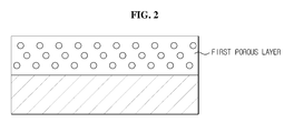
FIG. 2 is a view schematically illustrating a dispersed state of inorganic particles in a slurry in case only a first inorganic particle is used. -
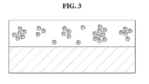
FIG. 3 is a view schematically illustrating a dispersed state of inorganic particles in a slurry in case only a second inorganic particle is used. -
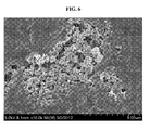
FIG. 4 illustrates a slurry in case only a first inorganic particle is used in process of manufacturing a separator according to Embodiment example 1. -
FIG. 5 illustrates a slurry in case only a second inorganic particle is used in process of manufacturing a separator according to Embodiment example 1. -
FIGS. 6 and7 are microscope photographic images of a surface observed after coating each slurry implemented according toFIGS. 4 and5 on a polyolefin substrate. -
FIG. 8 is a diagram schematically illustrating a process of manufacturing a separator according to an exemplary embodiment of the present disclosure. - Hereinafter, preferred embodiments of the present disclosure will be described in detail with reference to the accompanying drawings. Prior to the description, it should be understood that the terms used in the specification and the appended claims should not be construed as limited to general and dictionary meanings, but interpreted based on the meanings and concepts corresponding to technical aspects of the present disclosure on the basis of the principle that the inventor is allowed to define terms appropriately for the best explanation. Therefore, the description proposed herein is just a preferable example for the purpose of illustrations only, not intended to limit the scope of the disclosure, so it should be understood that other equivalents and modifications could be made thereto without departing from the spirit and scope of the disclosure.
- According to an aspect of the present disclosure, a separator for a secondary battery including a porous substrate having a pore, a first porous coating layer, and a second porous coating layer is provided.
- Non-limiting examples of the porous substrate may be a polymer membrane, a multi-layered polymer membrane, or a woven or non-woven fabric formed from any one polymer selected from the group consisting of polyethylene, polypropylene, polyethyleneterephthalate, polybutyleneterephthalate, polyester, polyacetal, polyamide, polycarbonate, polyimide, polyetheretherketone, polyaryletherketone, polyetherimide, polyamideimide, polybenzimidazole, polyethersulfone, polyphenyleneoxide, cyclic olefin copolymer, polyphenylenesulfide and polyethylenenaphthalene, or mixtures thereof. In the presence of the porous substrate, insulation between both electrodes is maintained. A type, a thickness, a pore size, and a number of pores of the porous substrate, and particularly, in a case of a non-woven fabric, a thickness of a superfine fiber, may be adjusted in consideration of a melting temperature, easiness to manufacture, a porosity, ion movement, insulation, and the like.
- The first porous coating layer is formed by coating on at least one area among at least one surface and the pore of the porous substrate, and includes first inorganic particles and a binder polymer. The binder polymer is disposed in a part or all of the first inorganic particles and functions to couple and bond the first inorganic particles to one another.
- The second porous coating layer is formed by coating on the first porous coating layer, and includes second inorganic particles and a binder polymer. The binder polymer is disposed in a part or all of the second inorganic particles and functions to couple and bond the second inorganic particles to one another.
- A non-limiting example of the binder polymer may include any one selected from the group consisting of polyvinylidene fluoride-co-hexafluoro propylene (PVDF-co-HFP), polyvinylidene fluoride-co-trichloro ethylene, polyvinylidene fluoride-co-chlorotrifluoro ethylene, polymethyl methacrylate, polyacrylonitrile, polyvinylpyrrolidone, polyvinylacetate, polyethylene-co-vinyl acetate, polyethylene oxide, cellulose acetate, cellulose acetate butyrate, cellulose acetate propionate, cyanoethylpullulan, cyanoethylpolyvinylalcohol, cyanoethyl cellulose, cyanoethyl sucrose, pullulan, carboxyl methyl cellulose (CMC), acrylonitrile-styrene-butadiene copolymer, polyimide, polyvinylidenefluoride, polyacrylonitrile and styrene butadiene rubber (SBR), or mixtures thereof.
- As each of the first inorganic particles and the second inorganic particles, an inorganic particle having a dielectric constant greater than or equal to 5 and an inorganic particle having a lithium ion delivery capability (in a case of a lithium secondary battery), singularly or in combination, may be independently used. The inorganic particle having a dielectric constant greater than or equal to 5 may be any one selected from the group consisting of BaTiO3, Pb(Zrx,Ti1-x)O3 (PZT, 0<x<1), Pb1-xLaxZr1-yTiyO3 (PLZT, 0<x<1, 0<y<1), (1-x)Pb(Mg1/3Nb2/3)O3-xPbTiO3 (PMN-PT, 0<x<1), hafnia (HfO2), SrTiO3, SnO2, CeO2, MgO, NiO, CaO, ZnO, ZrO2, SiO2, Y2O3, Al2O3, SiC and TiO2, or mixtures thereof. The inorganic particle having a lithium ion delivery capability may be, as a non-limiting example, any one selected from the group consisting of lithium phosphate (Li3PO4), lithium titanium phosphate (LixTiy(PO4)3, 0<x<2, 0<y<3), lithium aluminum titanium phosphate (LixAlyTiz(PO4)3, 0<x<2, 0<y<1, 0<z<3), (LiAlTiP)xOy-based glass (0<x<4, 0<y<13), lithium lanthanum titanate (LixLayTiO3,0<x<2,0<y<3), lithium germanium thiophosphate (LixGeyPzSw, 0<x<4, 0<y<1, 0<z<1, 0<w<5), lithium nitride (LixNy, 0<x<4, 0<y<2), SiS2(LixSiySz,0<x<3,0<y<2,0<z<4)-based glass and P2S5(LixPySz, 0<x<3, 0<y<3, 0<z<7)-based glass, or mixtures thereof.
-
FIG. 1 illustrates a separator for a secondary battery manufactured according to an exemplary embodiment of the present disclosure, and accordingly, the present disclosure is not limited thereto. Referring toFIG. 1 , a detailed description is as follows. - The first inorganic particles correspond to a less porous or non-porous (solid) inorganic particle. The first inorganic particles have a Brunauer, Emmett & Teller (BET) surface area less than or equal to about 10 m2/g, and have little adsorption function dissimilar to the second inorganic particles or has a weak adsorption function, if any, however they are dispersed well in a slurry when forming a coating layer, and thus may be uniformly dispersed in a final porous coating layer.
- The second inorganic particles correspond to a relatively more porous inorganic particle when compared to the first inorganic particles. The second inorganic particles have a BET surface area in a range of about 10 to about 50 m2/g, or in a range of about 12 to about 30 m2/g. Also, an average pore size of the second inorganic particles may be in a range of about 2 to about 200 nm or in a range of about 5 to about 100 nm. In the second inorganic particles, when its BET surface area is less than the above range, it is difficult to implement an expected effect of the present disclosure, that is, a metal ion adsorption effect, and to improve dispersibility, a dispersant should be inputted in excess, which may exert a bad influence on the performance of a final product, that is, a battery. Meanwhile, when the average pore size is less than the above range, there is a shortcoming that a specific surface area increases dramatically, and when the average pore size exceeds 200 nm, the pore size becomes similar to a particle size and thereby a porosity effect expected from the present disclosure is greatly reduced.
- The metal ion corresponds to a metal ion released from a cathode or a cathode active material in an abnormal situation of the battery or even in a normal situation, and may be, for example, manganese (Mn), cobalt (Co), nickel (Ni), iron (Fe), and the like, based on a material for a cathode active material used. The metal ion may be adsorbed by, for example, electrical attraction, capillarity, and the like, within the pores of the second inorganic particles.
- By the distribution of the first inorganic particles and the second inorganic particles independently in each porous coating layer, each of the inorganic particles may show its unique characteristics respectively.
- For example, the first porous coating layer containing the first inorganic particles in the coating layer may include the inorganic particles dispersed uniformly in the coating layer by use of a relatively small amount of solvent (dispersion medium) or dispersant due to unique dispersibility of the first inorganic particles. Also, since the first porous coating uses a small amount of solvent or dispersant, the state of pores at an interface between the porous substrate and the first porous coating layer are excellently maintained. Accordingly, ionic conductivity and impregnation property with an electrolyte is greatly improved. Meanwhile, the second porous coating layer containing the second inorganic particles in the coating layer shows excellent performance in removing the metal ion in the separator due to a unique adsorption capability caused by greater porous properties of the second inorganic particles.
- Each of the first inorganic particles and the second inorganic particles may have, independently, an average particle diameter in a range of about 0.01 to about 10 µm or in a range of about 0.1 to about 5 µm. When the average particle diameter of the inorganic particles falls within the above range, a reduction in dispersibility of the inorganic particles in the coating layer may be prevented or minimized, and the thickness and porosity of each of the porous coating layers may be properly adjusted.
- In the step of forming each porous coating layer, to provide a comparison of a dispersed state of inorganic particles in a slurry using various types of inorganic particles, a slurry including only the first inorganic particles and a slurry including only the second inorganic particles are shown in
FIGS. 2 and3 , respectively, and photographic images of the slurries are shown inFIGS. 4 and5 , respectively. -
FIGS. 2 and4 illustrate a dispersed state of inorganic particles in a slurry in case only a first inorganic particle is used in a process of manufacturing a separator, and a photographic image of the slurry, respectively. The first inorganic particles may be dispersed well and uniformly distributed in a final coating layer, dissimilar to the second inorganic particles. However, a separator having a final porous coating layer formed as described in the foregoing is difficult to sufficiently expect a function of adsorbing and removing a metal ion, for example, a metal ion released abnormally due to surface properties of less porous or non-porous inorganic particles. -
FIGS. 3 and5 illustrate a dispersed state of inorganic particles in a slurry in case only a second inorganic particle is used in a process of manufacturing a separator, and a photographic image of the slurry, respectively. In case only a second inorganic particle is used, a dispersed state of inorganic particles in a slurry (binder solution) is poor because the inorganic particles agglomerate together due to unique characteristics of the second inorganic particles, for example, a plurality of pores present therein, but a function of adsorbing and removing a metal ion released abnormally is sufficiently expected. - The content of the first inorganic particles may be in a range of about 70 to about 99 wt% or in a range of about 80 to about 95wt% of the first porous coating layer. When the first inorganic particles are included in the first porous coating layer within the above range, the first inorganic particles may be uniformly dispersed by use of a small amount of solvent or dispersant in the process of manufacturing the first porous coating layer, and besides, the first porous coating layer may form an assembly having excellent ionic conductivity and electrolyte impregnation together with the porous substrate underlying in contact therewith.
- Also, the content of the second inorganic particles may be in a range of about 30 to about 95 wt% or in a range of about 50 to about 90wt% of the second porous coating layer. When the second inorganic particles are included in the second porous coating layer within the above range, the second inorganic particles may have a great improvement in adsorption and removal of a metal ion generated in the battery due to their unique characteristics, that is, adsorption in the second porous coating layer.
-
FIGS. 6 and7 are microscope photographic images of a surface observed after coating each slurry implemented according toFIGS. 4 and5 on a polyolefin substrate. Referring to these photographic images, a dispersed state of inorganic particles in a slurry in the step of forming a coating layer as described in the foregoing may be verified directly. - There is no particular limitation on a pore size and porosity in a porous coating layer, but a preferred pore size is in a range of about 0.001 to about 10 µm and a preferred porosity is in a range of about 10 to about 90%. The pore size and porosity is primarily dependent on a size of inorganic particles, and for example, when inorganic particles having a particle diameter less than or equal to about 1 µm are used, a pore formed thereby also has a pore size less than or equal to about 1 µm. This pore structure is filled with an electrolyte solution to be injected later, and the filled electrolyte solution functions to transfer an ion. When the pore size and the porosity are less than about 0.001 µm and about 10%, respectively, the porous coating layer may serve as a resistance layer, and when the pore size and the porosity exceed about 10 µm and about 90%, respectively, mechanical properties may deteriorate. Preferably, a load amount of the porous coating layer for the porous substrate is in a range of about 5 to about 20 g/m2 based on the porous substrate when considering a function of the porous coating layer and suitability for a high capacity battery.
- According to another aspect of the present invention, a secondary battery including a cathode, an anode, and the above-described separator between the cathode and the anode is provided. Also, the secondary battery may correspond to a lithium secondary battery.
- The cathode, the anode, and the like are well known in the art, or may be easily manufactured by a process and/or method known in the art.
- The cathode is manufactured in a way of binding a cathode active material to a cathode current collector by a general method known in the art. In this instance, as the cathode active material, a conventional cathode active material usable in a cathode of a conventional electrochemical device may be used, and a non-limiting example of the cathode active material may include LiCoO2, LiNiO2, LiMnO2, LiMn2O4, Li(NiaCobMnc)O2 (0<a<1, 0<b<1, a+b+c=1), LiNi1-YCoYO2, LiCo1-YMnYO2, LiNi1-YMnYO2 (0≤Y<1), Li(NiaCobMnc)O4 (0<a<2, 0<b<2, a+b+c=2), LiMn2-ZNiZO4, LiMn2-ZCoZO4 (0<Z<2), LiCoPO4, LiFePO4, and mixtures thereof. Also, as the cathode current collector, a foil made from aluminum, nickel, or a combination thereof, may be used.
- The anode is manufactured in a way of binding an anode active material to an anode current collector by a general method known in the art. In this instance, as the anode active material, for example, carbon such as non-graphitizable carbon and graphite-based carbon; metal composite oxide such as LixFe2O3(0≤x≤1), LixWO2(0 ≤ x ≤ 1), and SnxMe1-xMe'yOz (Me: Mn, Fe, Pb, Ge; Me': Al, B, P, Si, elements of
Groups 1, 2, and 3 in the periodic table, halogen; 0<x ≤ 1; 1 ≤ y ≤ 3; 1 ≤ z ≤ 8); lithium metals; lithium alloys; silicon-based alloys; tin-based alloys; oxide such as SnO, SnO2, PbO, PbO2, Pb2O3, Pb3O4, Sb2O3, Sb2O4, Sb2O5, GeO, GeO2, Bi2O3, Bi2O4, and Bi2O5; conductive polymers such as polyacetylene; Li-Co-Ni-based materials, and the like, may be used. Meanwhile, as the anode current collector, stainless steel, nickel, copper, titanium, or alloys thereof, may be used. - Also, an electrolyte that may be inserted between the electrode and the separator may include a salt, for example, of A+B- structure, where A+ represents an ion including an alkali metal cation such as Li+, Na+ and K+, or combinations thereof, and B- represents an ion including an anion such as PF6 -, BF4 -, Cl-, Br-, I-, ClO4 -, AsF6 -, CH3CO2 -, CF3SO3 -, N(CF3SO2)2 - and C(CF2SO2)3 -, or combinations thereof, and such a salt may be dissolved or dissociated in an organic solvent including, but is not limited to, propylene carbonate (PC), ethylene carbonate (EC), diethyl carbonate (DEC), dimethyl carbonate (DMC), dipropyl carbonate (DPC), dimethylsulfoxide, acetonitrile, dimethoxyethane, diethoxyethane, tetrahydrofuran, N-methyl-2-pyrrolidone (NMP), ethylmethylcarbonate (EMC), gamma butyrolactone (γ-butyrolactone), or mixtures thereof.
- Injection of the electrolyte may be performed in a proper step among a battery fabrication process based on a manufacturing process and required physical properties of a final product. As a process of applying the separator of the present disclosure to a battery, besides a winding process generally used, a lamination/stacking and folding process of a separator and an electrode may be contemplated.
-
FIG. 8 is a diagram schematically illustrating a process of manufacturing a separator according to an exemplary embodiment of the present disclosure. According to another aspect of the present disclosure, there is provided a method of manufacturing a separator for a secondary battery including (S1) forming a first slurry, (S2) forming a second slurry, (S3) forming a first porous coating layer, (S4) forming a second porous coating layer. Hereinafter, a detailed description is provided with reference toFIG. 8 . - In S1, first, a first binder solution (or coating solution) is provided by dissolving a first binder polymer in a first solvent.
- The first binder polymer may be the same as described in the foregoing in the description of the separator for the secondary battery according to the present disclosure.
- The first solvent preferably has a similar solubility parameter to that of a binder polymer intended to use, and has a low melting point. This may allow uniform mixing and ease the subsequent removal of the first solvent. A non-limiting example of the first solvent may include any one selected from the group consisting of acetone, tetrahydrofuran, methylene chloride, chloroform, dimethylformamide, N-methyl-2-pyrrolidone (NMP) and cyclohexane, or mixtures thereof.
- A first slurry in which first inorganic particles are dispersed is formed by adding the first inorganic particles to the first binder solution. The first inorganic particles may be the same as described in the foregoing in the description of the separator for the secondary battery according to the present disclosure.
- The content of the first solvent may be in a range of about 40 to about 95 wt% or in a range of about 60 to about 90 wt% of the first slurry. The content of the first solvent within the range may help in maintaining a pore structure of a porous substrate while ensuring wettability of the first slurry on the porous substrate during subsequent coating.
- In S2, a second binder solution (or coating solution) is provided by dissolving a second binder polymer in a second solvent.
- Each of the second binder polymer and the second solvent may be, independently, identical to or different from the first binder polymer and the first solvent. A second slurry in which second inorganic particles are dispersed is formed by adding the second inorganic particles to the second binder solution. The second inorganic particles may be the same as described in the foregoing in the description of the separator for the secondary battery according to the present disclosure.
- The content of the second solvent may be in a range of about 40 to about 95 wt% or in a range of about 60 to about 90 wt% of the second slurry. The content of the second solvent within the range may prevent mixing of first and second porous coating layers to be formed until subsequent drying, allowing a stable interface state.
- In S3, the first slurry formed in S1 is applied to at least one surface of the porous substrate. Subsequently, the first solvent is removed from the first slurry by drying the first slurry-applied porous substrate. Due to the removal of the first solvent, a first coating layer is formed in at least one area among the at least one surface and the pore of the porous substrate.
- The porous substrate may be the same as described in the foregoing in the description of the separator according to the present disclosure, and the porous substrate may be manufactured by forming a pore through a conventional method known in the art, for example, a wet method using a solvent, a diluent or a pore forming agent, or a dry method using a stretching method, to ensure excellent permeability and porosity from the substrate material described in the foregoing.
- A method of coating the first slurry in which the first inorganic particles are dispersed onto the porous substrate may use a conventional coating method known in the art, and various methods may be used, for example, dip coating, die coating, roll coating, comma coating, or combinations thereof. Also, the first porous coating layer may be selectively formed on either one or both surfaces of the porous substrate. The first porous coating layer formed by this coating method may, in part, exist inside the porous substrate due to characteristics of the porous substrate, as well as on the surface of the porous substrate.
- In S4, the second slurry formed in S2 is applied onto the first porous coating layer formed in S3. Subsequently, the second solvent is removed from the second slurry by drying the second slurry-applied porous coating layer, and thereby the second porous coating layer is formed on the first porous coating layer.
- A method of coating the second slurry in which the second inorganic particles are dispersed onto the first porous coating layer may use a conventional coating method known in the art as well as various methods as described in the foregoing in the description of applying of the first porous coating layer.
- Also, besides the above-described separator, the cathode, the anode, and the electrolyte solution may be the same as well known in the art, and these may be commercially available or easily manufactured by a process and/or method known in the art.
- A secondary battery is manufactured by interposing the separator of the present disclosure between the cathode and the anode. Also, the secondary battery of the present disclosure may be a lithium secondary battery including a lithium metal secondary battery, a lithium ion secondary battery, a lithium polymer secondary battery, a lithium ion polymer secondary battery, and the like.
- Hereinafter, embodiments of the present disclosure will be described in detail. The embodiments of the present disclosure, however, may take several other forms, and the scope of the present disclosure should not be construed as being limited to the following examples. The embodiments of the present disclosure are provided to more fully explain the present disclosure to those having ordinary knowledge in the art to which the present disclosure pertains.
- A first binder solution was prepared by adding 5 parts by weight of polyvinylidenefluoride chlorotrifluoroethylene copolymer (PVdF-CTFE) as a first binder to 95 parts by weight of acetone as a first solvent, and dissolving at 50°C for about 12 hours or longer.
- A first slurry was prepared by mixing and dispersing, in the prepared first binder solution, first alumina particles having an average particle diameter of 0.7 µm and a BET surface area of 4 m2/g at a binder:inorganic matter ratio of 10:90. The dispersibility of the first slurry is the same as illustrated in
FIG. 4 . - A second binder solution was prepared by adding 5 parts by weight of polyvinylidenefluoride chlorotrifluoroethylene copolymer (PVdF-CTFE) as a second binder to 95 parts by weight of acetone as a second solvent, and dissolving at 50°C for about 12 hours or longer.
- A second slurry was prepared by mixing and dispersing, in the prepared second binder solution, second alumina particles having an average particle diameter of 0.4 µm, a BET surface area of 15 m2/g, and an average pore size of 100 nm at a binder:inorganic matter ratio of 20:80. The dispersibility of the second slurry is the same as illustrated in
FIG. 5 . - A first porous coating layer and a second porous coating layer were formed concurrently by coating the prepared first slurry and second slurry on a polyethylene porous substrate (Celgard, PP1615) having a thickness of 16 µm in a sequential order by a double-layer slide-slot coating method. The thicknesses of each coating layer were adjusted to about 5 µm and about 3 µm.
- A cathode active material slurry was prepared by adding, to 40 parts by weight of
- N-methyl-2-pyrrolidone (NMP) as a solvent, 90 parts by weight of lithium manganese composite oxide as a cathode active material, 5 parts by weight of carbon black as a conductive material, and 5 parts by weight of polyvinylidenefluoride (PVDF) as a binder. A cathode was manufactured by applying the cathode active material slurry to a 100 µm thick aluminum (Al) thin film of a cathode current collector and drying, and by compressing with a roll press.
- An anode active material slurry was prepared by adding, to 100 parts by weight of N-methyl-2-pyrrolidone (NMP) as a solvent, 95 parts by weight of carbon powder as an anode active material, 3 parts by weight of carbon black as a conductive material, and 2 parts by weight of polyvinylidenefluoride (PVDF) as a binder. An anode was manufactured by applying the anode active material slurry to a 90 µm thick copper (Cu) thin film of an anode current collector and drying, and by compressing with a roll press.
- Unit cells were assembled together by stacking the manufactured separator, cathode, and anode. Subsequently, a lithium secondary battery was manufactured by injecting an electrolyte solution (ethylene carbonate (EC)/dimethyl carbonate (DMC)/ethylmethylcarbonate (EMC) = 3/4/3 (volumetric ratio), 1M lithium hexyfluorophosphate (LiPF6)).
- A separator was manufactured by the same method of Embodiment example 1, except that only a first porous coating layer including first alumina particles was formed without a second porous coating layer including second alumina particles in a process of manufacturing a separator. Also, a lithium secondary battery was manufactured using the separator by the same method as Embodiment example 1.
- A separator was manufactured by the same method of Embodiment example 1, except that only a second porous coating layer including second alumina particles was formed without a first porous coating layer including first alumina particles in a process of manufacturing a separator. Also, a lithium secondary battery was manufactured using the separator by the same method as Embodiment example 1. However, an excessive binder content degrades permeability of the separator, resulting in a remarkable reduction in a lithium ion delivery capability.
- In the secondary batteries manufactured in Embodiment example 1 and Comparative example 1, an activation process was performed after injecting an electrolyte solution, and a capacity fade ratio of the secondary batteries was measured. The result was shown in Table 1.
Table 1 Initial 100 cycles 200 cycles 300 cycles Embodiment example 1 100% 99.6% 98.8% 97.6% Comparative example 1 100% 98.0% 95.2% 92.6% - Also, the batteries were disassembled, and for the anode surface, a detected amount of manganese ions was examined using inductively coupled plasma (ICP). The result was shown in Table 2.
Table 2 Separator surface (ppm) Anode surface (ppm) Embodiment example 1 145 150 Comparative example 1 135 180
Claims (19)
- A separator for a secondary battery, comprising:a porous substrate having a pore;a first porous coating layer formed by coating on at least one area among at least one surface and the pore of the porous substrate, and including first inorganic particles having a Brunauer, Emmett & Teller (BET) surface area less than or equal to 10 m2/g and a first binder polymer disposed in a part or all of the first inorganic particles to couple and bond the first inorganic particles to one another; anda second porous coating layer formed by coating on the first porous coating layer, and including second inorganic particles having a BET surface area in a range of 10 to 50 m2/g and a second binder polymer disposed in a part or all of the second inorganic particles to couple and bond the second inorganic particles to one another.
- The separator according to claim 1, wherein a content of the first inorganic particles is in a range of 70 to 99 wt% of the first porous coating layer.
- The separator according to claim 1, wherein a content of the second inorganic particles is in a range of 30 to 95 wt% of the second porous coating layer.
- The separator according to claim 1, wherein each of the first inorganic particles and the second inorganic particles is, independently, selected from the group consisting of an inorganic particle having a dielectric constant greater than or equal to 5, an inorganic particle having a lithium ion delivery capability, and a mixture thereof.
- The separator according to claim 1, wherein the porous substrate is a polymer membrane, a multi-layered polymer membrane, or a woven or non-woven fabric formed from any one polymer selected from the group consisting of polyethylene, polypropylene, polyethyleneterephthalate, polybutyleneterephthalate, polyester, polyacetal, polyamide, polycarbonate, polyimide, polyetheretherketone, polyaryletherketone, polyetherimide, polyamideimide, polybenzimidazole, polyethersulfone, polyphenyleneoxide, cyclic olefin copolymer, polyphenylenesulfide, and polyethylenenaphthalene, or mixtures thereof.
- The separator according to claim 1, wherein each of the first binder polymer and the second binder polymer is, independently, any one selected from the group consisting of polyvinylidene fluoride-co-hexafluoro propylene (PVDF-co-HFP), polyvinylidene fluoride-co-trichloro ethylene, polyvinylidene fluoride-co-chlorotrifluoro ethylene, polymethyl methacrylate, polyacrylonitrile, polyvinylpyrrolidone, polyvinylacetate, polyethylene-co-vinyl acetate, polyethylene oxide, cellulose acetate, cellulose acetate butyrate, cellulose acetate propionate, cyanoethylpullulan, cyanoethylpolyvinylalcohol, cyanoethyl cellulose, cyanoethyl sucrose, pullulan, carboxyl methyl cellulose (CMC), acrylonitrile-styrene-butadiene copolymer, polyimide, polyvinylidenefluoride, polyacrylonitrile and styrene butadiene rubber (SBR), or mixtures thereof.
- A secondary battery, comprising:a cathode;an anode; anda separator for a secondary battery according to any one of claims 1 through 6 interposed between the cathode and the anode.
- The secondary battery according to claim 7, wherein the secondary battery is a lithium secondary battery.
- A method of manufacturing a separator for a secondary battery, the method comprising:forming a first slurry in which first inorganic particles are dispersed, by adding the first inorganic particles having a Brunauer, Emmett & Teller (BET) surface area less than or equal to 10 m2/g to a first binder solution in which a first binder polymer is dissolved in a first solvent, followed by agitation;forming a second slurry in which second inorganic particles are dispersed, by adding the second inorganic particles having a BET surface area in a range of 10 to 50 m2/g to a second binder solution in which a second binder polymer is dissolved in a second solvent, followed by agitation;forming a first porous coating layer on at least one area among at least one surface and a pore of a porous substrate, by applying and drying the first slurry to the at least one surface of the porous substrate having the pore; andforming a second porous coating layer on the first porous coating layer, by applying and drying the second slurry to the first porous coating layer.
- The method according to claim 9, wherein the second inorganic particles have an average pore size in a range of 2 to 200 nm.
- The method according to claim 9, wherein the second inorganic particles have an average particle diameter in a range of 0.1 µm to 10 µm.
- The method according to claim 9, wherein each of the first solvent and the second solvent is, independently, any one selected from the group consisting of acetone, tetrahydrofuran, methylene chloride, chloroform, dimethylformamide, N-methyl-2-pyrrolidone (NMP) and cyclohexane, or mixtures thereof.
- The method according to claim 9, wherein a content of the first solvent is in a range of 40 to 95 wt% of the first slurry.
- The method according to claim 9, wherein a content of the second solvent is in a range of 40 to 95 wt% of the second slurry.
- The method according to claim 9, wherein each of the first inorganic particles and the second inorganic particles is, independently, selected from the group consisting of an inorganic particle having a dielectric constant greater than or equal to 5, an inorganic particle having a lithium ion delivery capability, and a mixture thereof.
- The method according to claim 9, wherein the porous substrate is a polymer membrane, a multi-layered polymer membrane, or a woven or non-woven fabric formed from any one polymer selected from the group consisting of polyethylene, polypropylene, polyethyleneterephthalate, polybutyleneterephthalate, polyester, polyacetal, polyamide, polycarbonate, polyimide, polyetheretherketone, polyaryletherketone, polyetherimide, polyamideimide, polybenzimidazole, polyethersulfone, polyphenyleneoxide, cyclic olefin copolymer, polyphenylenesulfide, and polyethylenenaphthalene, or mixtures thereof.
- The method according to claim 9, wherein each of the first binder polymer and the second binder polymer is, independently, any one selected from the group consisting of polyvinylidene fluoride-co-hexafluoro propylene (PVDF-co-HFP), polyvinylidene fluoride-co-trichloro ethylene, polyvinylidene fluoride-co-chlorotrifluoro ethylene, polymethyl methacrylate, polyacrylonitrile, polyvinylpyrrolidone, polyvinylacetate, polyethylene-co-vinyl acetate, polyethylene oxide, cellulose acetate, cellulose acetate butyrate, cellulose acetate propionate, cyanoethylpullulan, cyanoethylpolyvinylalcohol, cyanoethyl cellulose, cyanoethyl sucrose, pullulan, carboxyl methyl cellulose (CMC), acrylonitrile-styrene-butadiene copolymer, polyimide, polyvinylidenefluoride, polyacrylonitrile and styrene butadiene rubber (SBR), or mixtures thereof.
- The separator according to claim 1, wherein the second inorganic particles have an average pore size in a range of 2 to 200 nm.
- The separator according to claim 1, wherein the second inorganic particles have an average particle diameter in a range of 0.1 µm to 10 µm.
Applications Claiming Priority (2)
| Application Number | Priority Date | Filing Date | Title |
|---|---|---|---|
| KR20120138022 | 2012-11-30 | ||
| PCT/KR2013/011035 WO2014084681A1 (en) | 2012-11-30 | 2013-11-29 | Secondary battery separation membrane including double porous coating layers of inorganic particles having different surface properties, secondary battery including same, and method for manufacturing separation membrane |
Publications (3)
| Publication Number | Publication Date |
|---|---|
| EP2806483A1 true EP2806483A1 (en) | 2014-11-26 |
| EP2806483A4 EP2806483A4 (en) | 2016-03-30 |
| EP2806483B1 EP2806483B1 (en) | 2020-01-01 |
Family
ID=51125303
Family Applications (1)
| Application Number | Title | Priority Date | Filing Date |
|---|---|---|---|
| EP13857836.4A Active EP2806483B1 (en) | 2012-11-30 | 2013-11-29 | Separator for secondary battery comprising dual porous coating layer of inorganic particles with different surface characteristics, secondary battery comprising the same, and method of manufacturing the separator |
Country Status (6)
| Country | Link |
|---|---|
| US (1) | US9698396B2 (en) |
| EP (1) | EP2806483B1 (en) |
| JP (1) | JP6045121B2 (en) |
| KR (1) | KR101541473B1 (en) |
| HU (1) | HUE048838T2 (en) |
| WO (1) | WO2014084681A1 (en) |
Cited By (1)
| Publication number | Priority date | Publication date | Assignee | Title |
|---|---|---|---|---|
| EP4203165A4 (en) * | 2020-09-07 | 2025-06-11 | LG Energy Solution, Ltd. | Separator for electrochemical device and method for manufacturing same |
Families Citing this family (50)
| Publication number | Priority date | Publication date | Assignee | Title |
|---|---|---|---|---|
| US9337474B1 (en) | 2010-05-20 | 2016-05-10 | Halbert P. Fischel | Electrodes for electrochemical cells |
| JP6008198B2 (en) * | 2013-04-02 | 2016-10-19 | トヨタ自動車株式会社 | Secondary battery and separator for the battery |
| US10522856B2 (en) | 2014-12-03 | 2019-12-31 | Global Energy Science, Llc | Electrochemical cells with mobile electrolyte |
| JP6495042B2 (en) * | 2015-02-18 | 2019-04-03 | 三井化学株式会社 | Separator and manufacturing method thereof, lithium ion secondary battery |
| JP6630811B2 (en) * | 2015-07-10 | 2020-01-15 | エルジー・ケム・リミテッド | Separator and electrochemical device including the same |
| KR101880237B1 (en) * | 2015-08-28 | 2018-08-17 | 삼성에스디아이 주식회사 | Porous heat-resistant layer, separator comprising the porous heat-resistant layer, secondary battery using the separator, and method for preparing thereof |
| KR101904296B1 (en) * | 2015-12-22 | 2018-11-13 | 삼성에스디아이 주식회사 | A separator comprising porous bonding layer and an electrochemical battery comprising the separator |
| JP2017162753A (en) * | 2016-03-11 | 2017-09-14 | 三菱製紙株式会社 | Separator for lithium ion secondary battery |
| US10734627B2 (en) * | 2016-04-01 | 2020-08-04 | Lg Chen, Ltd. | Separator comprising an adhesion layer for an electrochemical device and an electrode assembly comprising the same |
| WO2017196656A1 (en) | 2016-05-13 | 2017-11-16 | 3M Innovative Properties Company | Multilayer articles including coatings on microfiltration membrane substrates and methods of making same |
| KR102314039B1 (en) * | 2016-07-28 | 2021-10-18 | 삼성에스디아이 주식회사 | Electrolyte for lithium metal battery and lithium metal battery comprising the same |
| KR102016717B1 (en) * | 2016-08-26 | 2019-10-14 | 주식회사 엘지화학 | An electrode lead member for an electrochemical device |
| CN107785519A (en) * | 2016-08-29 | 2018-03-09 | 比亚迪股份有限公司 | A kind of composite membrane of polymer and preparation method thereof and the lithium ion battery for including it |
| WO2018089323A2 (en) * | 2016-11-10 | 2018-05-17 | Global Energy Science, Llc | Dielectric separator compressor |
| HUE061620T2 (en) | 2016-12-02 | 2023-07-28 | Asahi Chemical Ind | Nonaqueous electrolyte battery inorganic particles, and nonaqueous electrolyte battery using these |
| WO2018163203A1 (en) * | 2017-03-06 | 2018-09-13 | Council Of Scientific And Industrial Research | Porous polybenzimidazole as separator for lithium ion batteries |
| US11135554B2 (en) | 2017-03-15 | 2021-10-05 | 3M Innovative Properties Company | Multilayer articles including coatings containing metal on microfiltration membrane substrates |
| JP6841706B2 (en) * | 2017-03-30 | 2021-03-10 | 三菱製紙株式会社 | Lithium ion battery separator |
| JP7117480B2 (en) * | 2017-08-29 | 2022-08-15 | パナソニックIpマネジメント株式会社 | Non-aqueous electrolyte secondary battery |
| KR20190026530A (en) * | 2017-09-05 | 2019-03-13 | 롯데케미칼 주식회사 | Separator of redox flow battery, preparation method for separator of flow battery, and redox flow battery |
| WO2019065062A1 (en) * | 2017-09-29 | 2019-04-04 | パナソニックIpマネジメント株式会社 | Nonaqueous electrolyte secondary battery |
| CN110832672B (en) | 2017-10-20 | 2023-05-05 | 株式会社Lg新能源 | Separator and electrochemical device comprising the same |
| KR102392542B1 (en) * | 2017-11-02 | 2022-04-28 | 주식회사 엘지에너지솔루션 | Slurry composition for separator of secondary battery and separator for secondary battery comprising the same |
| CN108123089A (en) * | 2017-12-12 | 2018-06-05 | 上海恩捷新材料科技股份有限公司 | Isolation film and electrochemical appliance |
| WO2019131193A1 (en) * | 2017-12-27 | 2019-07-04 | パナソニックIpマネジメント株式会社 | Non-aqueous electrolyte secondary battery |
| KR102287767B1 (en) | 2018-01-18 | 2021-08-10 | 주식회사 엘지에너지솔루션 | Separators for lithium secondary battery and lithium secondary battery comprising the same |
| KR102210884B1 (en) * | 2018-02-26 | 2021-02-02 | 삼성에스디아이 주식회사 | Separator, method for preparing the same, and lithium battery comprising the same |
| KR102385925B1 (en) * | 2018-11-05 | 2022-04-11 | 주식회사 엘지에너지솔루션 | Separator for electrochemical device and electrochemical device containing the same |
| KR102804447B1 (en) * | 2018-12-21 | 2025-05-13 | 주식회사 엘지화학 | A separator for an electrochemical device comprising a multi-layered porous coating layer and a method for manufacturing the same |
| KR102414357B1 (en) * | 2019-01-18 | 2022-06-29 | 주식회사 엘지에너지솔루션 | Separator comprising dual coating layers and secondary battery comprising the same |
| CN109860488A (en) * | 2019-01-23 | 2019-06-07 | 东莞市魔方新能源科技有限公司 | Lithium battery diaphragm coating paste and preparation method thereof and diaphragm containing the slurry |
| KR102331720B1 (en) * | 2019-02-18 | 2021-11-26 | 삼성에스디아이 주식회사 | Separator, Lithium battery containing the Separator |
| KR102383075B1 (en) * | 2019-03-07 | 2022-04-04 | 삼성에스디아이 주식회사 | Separator for rechargeable lithium battery and rechargeable lithium battery including the same |
| CN117996356A (en) | 2019-03-18 | 2024-05-07 | 宁德新能源科技有限公司 | Separator membrane and electrochemical device |
| EP3930042A4 (en) * | 2019-03-29 | 2023-07-19 | GS Yuasa International Ltd. | Electricity storage element |
| WO2021020887A1 (en) * | 2019-07-30 | 2021-02-04 | 주식회사 엘지화학 | Composite separator for electrochemical device, and electrochemical device including same |
| KR102282911B1 (en) * | 2019-10-14 | 2021-07-27 | 경상국립대학교산학협력단 | Sencondary battery, and manufacturing method thereof |
| KR102764920B1 (en) * | 2019-10-18 | 2025-02-06 | 주식회사 엘지에너지솔루션 | A separator for electrochemical device, an electrochemical device comprising the separator and a method for manufacturing the same |
| KR102299018B1 (en) * | 2019-12-04 | 2021-09-07 | 한국생산기술연구원 | Ion-exchange membrane for redox flow battery, method of preparing same, and redox flow battery comprising same |
| WO2022015118A1 (en) * | 2020-07-16 | 2022-01-20 | 주식회사 엘지에너지솔루션 | Battery cell and method for manufacturing same |
| US20230411789A1 (en) * | 2021-01-25 | 2023-12-21 | Lg Chem, Ltd. | Separator for Lithium Secondary Battery and Lithium Secondary Battery Including the Same |
| US20230223659A1 (en) * | 2021-01-25 | 2023-07-13 | Lg Chem, Ltd. | Separator for Lithium Secondary Battery and Lithium Secondary Battery Including the Same |
| US12126044B2 (en) * | 2021-05-10 | 2024-10-22 | GM Global Technology Operations LLC | Separators for electrochemical cells and electrochemical cells including the same |
| CN117099254A (en) * | 2021-08-27 | 2023-11-21 | 株式会社Lg新能源 | Separator for electrochemical device and electrode assembly and electrochemical device including the separator |
| CN217848193U (en) * | 2022-04-14 | 2022-11-18 | 阳光储能技术有限公司 | an energy storage system |
| CN119698712A (en) * | 2023-04-10 | 2025-03-25 | 宁德时代新能源科技股份有限公司 | Separator and related secondary battery and electrical device |
| EP4586387A4 (en) * | 2023-04-21 | 2026-03-18 | Lg Energy Solution Ltd | SEPARATOR FOR ELECTROCHEMICAL DEVICE AND ELECTROCHEMICAL DEVICE WITH WHICH |
| KR20250021819A (en) | 2023-08-07 | 2025-02-14 | (주) 딥스마텍 | Separator for secondary battery including polymer protective layer and manufacturing method thereof |
| CN118369814A (en) * | 2023-09-28 | 2024-07-19 | 宁德新能源科技有限公司 | Separator, secondary battery and electronic device including the same |
| CN120221930B (en) * | 2025-05-28 | 2025-08-26 | 浙江晶科储能有限公司 | Secondary battery, preparation method thereof, energy storage system and electric equipment |
Family Cites Families (21)
| Publication number | Priority date | Publication date | Assignee | Title |
|---|---|---|---|---|
| KR100472503B1 (en) * | 2002-06-07 | 2005-03-10 | 삼성에스디아이 주식회사 | Separator and lithium battery adopting the same |
| JP4478767B2 (en) * | 2003-03-31 | 2010-06-09 | 独立行政法人理化学研究所 | Method for producing metal oxide nano thin film, nano thin film obtained by the method, and dielectric material having the nano thin film |
| DE10347567A1 (en) | 2003-10-14 | 2005-05-12 | Degussa | Electric separator with shut-off mechanism, process for its manufacture and use in lithium batteries |
| KR100790280B1 (en) * | 2004-03-30 | 2008-01-02 | 마쯔시다덴기산교 가부시키가이샤 | Nonaqueous Electrolyte Secondary Battery |
| JP4743747B2 (en) | 2004-12-08 | 2011-08-10 | 日立マクセル株式会社 | Separator, manufacturing method thereof, and nonaqueous electrolyte battery |
| WO2006068143A1 (en) * | 2004-12-24 | 2006-06-29 | Matsushita Electric Industrial Co., Ltd. | Rechargeable battery with nonaqueous electrolyte |
| TWI330136B (en) * | 2005-11-28 | 2010-09-11 | Lg Chemical Ltd | Organic/inorganic composite porous membrane and electrochemical device using the same |
| BRPI0620590B1 (en) | 2005-12-06 | 2019-07-09 | Lg Chem, Ltd. | ORGANIC / INORGANIC COMPOSITE SEPARATOR, METHOD FOR MANUFACTURING AN ORGANIC / INORGANIC COMPOSITE SEPARATOR AND ELECTROCHEMICAL DEVICE |
| JP5055865B2 (en) | 2006-07-19 | 2012-10-24 | パナソニック株式会社 | Lithium ion secondary battery |
| KR100824851B1 (en) * | 2006-10-27 | 2008-04-23 | 삼성에스디아이 주식회사 | Electrode assembly and secondary battery having same |
| JP5309628B2 (en) * | 2007-03-23 | 2013-10-09 | 住友化学株式会社 | Porous film |
| JP5196908B2 (en) * | 2007-08-15 | 2013-05-15 | 三菱樹脂株式会社 | Laminated porous film, battery separator and battery using the same |
| JP5640311B2 (en) * | 2007-09-28 | 2014-12-17 | 住友化学株式会社 | Lithium composite metal oxide and non-aqueous electrolyte secondary battery |
| JP2009146822A (en) * | 2007-12-17 | 2009-07-02 | Panasonic Corp | Nonaqueous electrolyte secondary battery |
| KR100983161B1 (en) * | 2008-01-11 | 2010-09-20 | 삼성에스디아이 주식회사 | Electrode assembly and secondary battery having same |
| EP2242133B1 (en) | 2008-02-04 | 2021-05-19 | Mitsubishi Chemical Corporation | Multi-layer structured carbonaceous material, process for producing the same, and nonaqueous secondary battery adopting the same |
| CN102388483B (en) * | 2009-01-12 | 2016-04-06 | A123系统有限责任公司 | Laminate battery and its preparation method |
| WO2010143677A1 (en) * | 2009-06-10 | 2010-12-16 | 日立マクセル株式会社 | Separator for electrochemical element, and electrochemical element including same |
| US20110311855A1 (en) * | 2009-09-03 | 2011-12-22 | Shufu Peng | Methods and systems for making separators and devices arising therefrom |
| JP5234662B2 (en) * | 2009-09-17 | 2013-07-10 | 日立マクセル株式会社 | Battery separator and lithium secondary battery |
| JP2012004103A (en) * | 2010-02-25 | 2012-01-05 | Sumitomo Chemical Co Ltd | Inorganic oxide powder, inorganic oxide-containing slurry, lithium ion secondary battery using the slurry and method of producing the same |
-
2013
- 2013-11-29 HU HUE13857836A patent/HUE048838T2/en unknown
- 2013-11-29 KR KR1020130147978A patent/KR101541473B1/en active Active
- 2013-11-29 WO PCT/KR2013/011035 patent/WO2014084681A1/en not_active Ceased
- 2013-11-29 EP EP13857836.4A patent/EP2806483B1/en active Active
- 2013-11-29 JP JP2015527403A patent/JP6045121B2/en active Active
-
2014
- 2014-07-14 US US14/330,037 patent/US9698396B2/en active Active
Cited By (1)
| Publication number | Priority date | Publication date | Assignee | Title |
|---|---|---|---|---|
| EP4203165A4 (en) * | 2020-09-07 | 2025-06-11 | LG Energy Solution, Ltd. | Separator for electrochemical device and method for manufacturing same |
Also Published As
| Publication number | Publication date |
|---|---|
| KR20140070484A (en) | 2014-06-10 |
| CN104205415A (en) | 2014-12-10 |
| JP6045121B2 (en) | 2016-12-14 |
| WO2014084681A1 (en) | 2014-06-05 |
| KR101541473B1 (en) | 2015-08-05 |
| EP2806483B1 (en) | 2020-01-01 |
| EP2806483A4 (en) | 2016-03-30 |
| JP2015524991A (en) | 2015-08-27 |
| US9698396B2 (en) | 2017-07-04 |
| US20140322586A1 (en) | 2014-10-30 |
| HUE048838T2 (en) | 2020-08-28 |
Similar Documents
| Publication | Publication Date | Title |
|---|---|---|
| EP2806483B1 (en) | Separator for secondary battery comprising dual porous coating layer of inorganic particles with different surface characteristics, secondary battery comprising the same, and method of manufacturing the separator | |
| KR102311624B1 (en) | Separator with adhesive layer for lithium secondary battery | |
| US9083036B2 (en) | Separator comprising microcapsules and electrochemical device having the same | |
| KR101745631B1 (en) | Separator for secondary battery comprising dual porous coating layers of inorganic particles with different average particle diameter, secondary battery comprising the same, and method for preparing the separator | |
| KR101662638B1 (en) | Separator having binder layer, electrochemical device comprising the separator, and method of preparing the separator | |
| KR101730574B1 (en) | Separator for secondary battery comprising porous coating layer for adsorbing metal ion, secondary battery comprising the same, and method for preparing the separator | |
| KR101739080B1 (en) | A separator having microcapsules and electrochemical device containing the same | |
| KR101446163B1 (en) | Separator for electrochemical devices with improved adhesion, and electrochemical devices containing the same | |
| US10673045B2 (en) | Secondary battery with improved life characteristics | |
| US10586967B2 (en) | Cellulose-based multilayer separator | |
| KR101750324B1 (en) | A separator having heat absorbing materials and electrochemical device containing the same | |
| KR102830174B1 (en) | A separator for an electrochemical device and an electrochemical device comprising the same | |
| KR102207528B1 (en) | POROUS SEPARATING FiLM AND ELECTROCHEMICAL DEVICE CONTAINING THE SAME | |
| KR102524662B1 (en) | A binder resin composition and a separator for an electrochemical device including the same | |
| EP4369503A1 (en) | Method for manufacturing separator for lithium secondary battery, separator for lithium secondary battery manufactured thereby, and method for manufacturing lithium secondary battery using same | |
| KR102654531B1 (en) | Preparing method of separator for lithium secondary battery, separator for lithium secondary battery manufactured therefrom, and preparing method of lithium secondary battery using the same | |
| KR101715696B1 (en) | Secondary battery with improved extended performances | |
| CN104205415B (en) | Separator for secondary battery comprising double porous coating of inorganic particles having different surface characteristics, secondary battery comprising the same, and method for producing the same | |
| KR20260044791A (en) | Seperaor for electrochmical device and electrochmical device including the same | |
| CN117882242A (en) | Method for manufacturing a separator for a lithium secondary battery, separator for a lithium secondary battery manufactured thereby, and method for manufacturing a lithium secondary battery using the separator | |
| KR20150051506A (en) | Separator for electrochemical device and Electrochemical device comprising the same |
Legal Events
| Date | Code | Title | Description |
|---|---|---|---|
| PUAI | Public reference made under article 153(3) epc to a published international application that has entered the european phase |
Free format text: ORIGINAL CODE: 0009012 |
|
| 17P | Request for examination filed |
Effective date: 20140821 |
|
| AK | Designated contracting states |
Kind code of ref document: A1 Designated state(s): AL AT BE BG CH CY CZ DE DK EE ES FI FR GB GR HR HU IE IS IT LI LT LU LV MC MK MT NL NO PL PT RO RS SE SI SK SM TR |
|
| RAP1 | Party data changed (applicant data changed or rights of an application transferred) |
Owner name: LG CHEM, LTD. Owner name: TORAY BATTERY SEPARATOR FILM CO., LTD. |
|
| DAX | Request for extension of the european patent (deleted) | ||
| RA4 | Supplementary search report drawn up and despatched (corrected) |
Effective date: 20160229 |
|
| RIC1 | Information provided on ipc code assigned before grant |
Ipc: H01M 2/16 20060101AFI20160223BHEP |
|
| RAP1 | Party data changed (applicant data changed or rights of an application transferred) |
Owner name: LG CHEM, LTD. Owner name: TORAY INDUSTRIES, INC. |
|
| STAA | Information on the status of an ep patent application or granted ep patent |
Free format text: STATUS: EXAMINATION IS IN PROGRESS |
|
| 17Q | First examination report despatched |
Effective date: 20180404 |
|
| GRAP | Despatch of communication of intention to grant a patent |
Free format text: ORIGINAL CODE: EPIDOSNIGR1 |
|
| STAA | Information on the status of an ep patent application or granted ep patent |
Free format text: STATUS: GRANT OF PATENT IS INTENDED |
|
| INTG | Intention to grant announced |
Effective date: 20190102 |
|
| GRAS | Grant fee paid |
Free format text: ORIGINAL CODE: EPIDOSNIGR3 |
|
| GRAA | (expected) grant |
Free format text: ORIGINAL CODE: 0009210 |
|
| STAA | Information on the status of an ep patent application or granted ep patent |
Free format text: STATUS: THE PATENT HAS BEEN GRANTED |
|
| AK | Designated contracting states |
Kind code of ref document: B1 Designated state(s): AL AT BE BG CH CY CZ DE DK EE ES FI FR GB GR HR HU IE IS IT LI LT LU LV MC MK MT NL NO PL PT RO RS SE SI SK SM TR |
|
| REG | Reference to a national code |
Ref country code: GB Ref legal event code: FG4D |
|
| REG | Reference to a national code |
Ref country code: CH Ref legal event code: EP Ref country code: AT Ref legal event code: REF Ref document number: 1220917 Country of ref document: AT Kind code of ref document: T Effective date: 20200115 |
|
| REG | Reference to a national code |
Ref country code: IE Ref legal event code: FG4D |
|
| REG | Reference to a national code |
Ref country code: DE Ref legal event code: R096 Ref document number: 602013064723 Country of ref document: DE |
|
| REG | Reference to a national code |
Ref country code: NL Ref legal event code: MP Effective date: 20200101 |
|
| REG | Reference to a national code |
Ref country code: LT Ref legal event code: MG4D |
|
| PG25 | Lapsed in a contracting state [announced via postgrant information from national office to epo] |
Ref country code: CZ Free format text: LAPSE BECAUSE OF FAILURE TO SUBMIT A TRANSLATION OF THE DESCRIPTION OR TO PAY THE FEE WITHIN THE PRESCRIBED TIME-LIMIT Effective date: 20200101 Ref country code: RS Free format text: LAPSE BECAUSE OF FAILURE TO SUBMIT A TRANSLATION OF THE DESCRIPTION OR TO PAY THE FEE WITHIN THE PRESCRIBED TIME-LIMIT Effective date: 20200101 Ref country code: NL Free format text: LAPSE BECAUSE OF FAILURE TO SUBMIT A TRANSLATION OF THE DESCRIPTION OR TO PAY THE FEE WITHIN THE PRESCRIBED TIME-LIMIT Effective date: 20200101 Ref country code: NO Free format text: LAPSE BECAUSE OF FAILURE TO SUBMIT A TRANSLATION OF THE DESCRIPTION OR TO PAY THE FEE WITHIN THE PRESCRIBED TIME-LIMIT Effective date: 20200401 Ref country code: PT Free format text: LAPSE BECAUSE OF FAILURE TO SUBMIT A TRANSLATION OF THE DESCRIPTION OR TO PAY THE FEE WITHIN THE PRESCRIBED TIME-LIMIT Effective date: 20200527 Ref country code: FI Free format text: LAPSE BECAUSE OF FAILURE TO SUBMIT A TRANSLATION OF THE DESCRIPTION OR TO PAY THE FEE WITHIN THE PRESCRIBED TIME-LIMIT Effective date: 20200101 Ref country code: LT Free format text: LAPSE BECAUSE OF FAILURE TO SUBMIT A TRANSLATION OF THE DESCRIPTION OR TO PAY THE FEE WITHIN THE PRESCRIBED TIME-LIMIT Effective date: 20200101 |
|
| REG | Reference to a national code |
Ref country code: HU Ref legal event code: AG4A Ref document number: E048838 Country of ref document: HU |
|
| PG25 | Lapsed in a contracting state [announced via postgrant information from national office to epo] |
Ref country code: BG Free format text: LAPSE BECAUSE OF FAILURE TO SUBMIT A TRANSLATION OF THE DESCRIPTION OR TO PAY THE FEE WITHIN THE PRESCRIBED TIME-LIMIT Effective date: 20200401 Ref country code: LV Free format text: LAPSE BECAUSE OF FAILURE TO SUBMIT A TRANSLATION OF THE DESCRIPTION OR TO PAY THE FEE WITHIN THE PRESCRIBED TIME-LIMIT Effective date: 20200101 Ref country code: SE Free format text: LAPSE BECAUSE OF FAILURE TO SUBMIT A TRANSLATION OF THE DESCRIPTION OR TO PAY THE FEE WITHIN THE PRESCRIBED TIME-LIMIT Effective date: 20200101 Ref country code: IS Free format text: LAPSE BECAUSE OF FAILURE TO SUBMIT A TRANSLATION OF THE DESCRIPTION OR TO PAY THE FEE WITHIN THE PRESCRIBED TIME-LIMIT Effective date: 20200501 Ref country code: HR Free format text: LAPSE BECAUSE OF FAILURE TO SUBMIT A TRANSLATION OF THE DESCRIPTION OR TO PAY THE FEE WITHIN THE PRESCRIBED TIME-LIMIT Effective date: 20200101 Ref country code: GR Free format text: LAPSE BECAUSE OF FAILURE TO SUBMIT A TRANSLATION OF THE DESCRIPTION OR TO PAY THE FEE WITHIN THE PRESCRIBED TIME-LIMIT Effective date: 20200402 |
|
| REG | Reference to a national code |
Ref country code: DE Ref legal event code: R097 Ref document number: 602013064723 Country of ref document: DE |
|
| PG25 | Lapsed in a contracting state [announced via postgrant information from national office to epo] |
Ref country code: EE Free format text: LAPSE BECAUSE OF FAILURE TO SUBMIT A TRANSLATION OF THE DESCRIPTION OR TO PAY THE FEE WITHIN THE PRESCRIBED TIME-LIMIT Effective date: 20200101 Ref country code: SM Free format text: LAPSE BECAUSE OF FAILURE TO SUBMIT A TRANSLATION OF THE DESCRIPTION OR TO PAY THE FEE WITHIN THE PRESCRIBED TIME-LIMIT Effective date: 20200101 Ref country code: SK Free format text: LAPSE BECAUSE OF FAILURE TO SUBMIT A TRANSLATION OF THE DESCRIPTION OR TO PAY THE FEE WITHIN THE PRESCRIBED TIME-LIMIT Effective date: 20200101 Ref country code: DK Free format text: LAPSE BECAUSE OF FAILURE TO SUBMIT A TRANSLATION OF THE DESCRIPTION OR TO PAY THE FEE WITHIN THE PRESCRIBED TIME-LIMIT Effective date: 20200101 Ref country code: RO Free format text: LAPSE BECAUSE OF FAILURE TO SUBMIT A TRANSLATION OF THE DESCRIPTION OR TO PAY THE FEE WITHIN THE PRESCRIBED TIME-LIMIT Effective date: 20200101 Ref country code: ES Free format text: LAPSE BECAUSE OF FAILURE TO SUBMIT A TRANSLATION OF THE DESCRIPTION OR TO PAY THE FEE WITHIN THE PRESCRIBED TIME-LIMIT Effective date: 20200101 |
|
| PLBE | No opposition filed within time limit |
Free format text: ORIGINAL CODE: 0009261 |
|
| STAA | Information on the status of an ep patent application or granted ep patent |
Free format text: STATUS: NO OPPOSITION FILED WITHIN TIME LIMIT |
|
| REG | Reference to a national code |
Ref country code: AT Ref legal event code: MK05 Ref document number: 1220917 Country of ref document: AT Kind code of ref document: T Effective date: 20200101 |
|
| REG | Reference to a national code |
Ref country code: DE Ref legal event code: R079 Ref document number: 602013064723 Country of ref document: DE Free format text: PREVIOUS MAIN CLASS: H01M0002160000 Ipc: H01M0050409000 |
|
| 26N | No opposition filed |
Effective date: 20201002 |
|
| PG25 | Lapsed in a contracting state [announced via postgrant information from national office to epo] |
Ref country code: AT Free format text: LAPSE BECAUSE OF FAILURE TO SUBMIT A TRANSLATION OF THE DESCRIPTION OR TO PAY THE FEE WITHIN THE PRESCRIBED TIME-LIMIT Effective date: 20200101 Ref country code: IT Free format text: LAPSE BECAUSE OF FAILURE TO SUBMIT A TRANSLATION OF THE DESCRIPTION OR TO PAY THE FEE WITHIN THE PRESCRIBED TIME-LIMIT Effective date: 20200101 |
|
| PG25 | Lapsed in a contracting state [announced via postgrant information from national office to epo] |
Ref country code: SI Free format text: LAPSE BECAUSE OF FAILURE TO SUBMIT A TRANSLATION OF THE DESCRIPTION OR TO PAY THE FEE WITHIN THE PRESCRIBED TIME-LIMIT Effective date: 20200101 Ref country code: PL Free format text: LAPSE BECAUSE OF FAILURE TO SUBMIT A TRANSLATION OF THE DESCRIPTION OR TO PAY THE FEE WITHIN THE PRESCRIBED TIME-LIMIT Effective date: 20200101 |
|
| PG25 | Lapsed in a contracting state [announced via postgrant information from national office to epo] |
Ref country code: MC Free format text: LAPSE BECAUSE OF FAILURE TO SUBMIT A TRANSLATION OF THE DESCRIPTION OR TO PAY THE FEE WITHIN THE PRESCRIBED TIME-LIMIT Effective date: 20200101 |
|
| REG | Reference to a national code |
Ref country code: CH Ref legal event code: PL |
|
| PG25 | Lapsed in a contracting state [announced via postgrant information from national office to epo] |
Ref country code: LU Free format text: LAPSE BECAUSE OF NON-PAYMENT OF DUE FEES Effective date: 20201129 |
|
| REG | Reference to a national code |
Ref country code: BE Ref legal event code: MM Effective date: 20201130 |
|
| PG25 | Lapsed in a contracting state [announced via postgrant information from national office to epo] |
Ref country code: LI Free format text: LAPSE BECAUSE OF NON-PAYMENT OF DUE FEES Effective date: 20201130 Ref country code: CH Free format text: LAPSE BECAUSE OF NON-PAYMENT OF DUE FEES Effective date: 20201130 |
|
| REG | Reference to a national code |
Ref country code: IE Ref legal event code: MM4A |
|
| PG25 | Lapsed in a contracting state [announced via postgrant information from national office to epo] |
Ref country code: IE Free format text: LAPSE BECAUSE OF NON-PAYMENT OF DUE FEES Effective date: 20201129 |
|
| PG25 | Lapsed in a contracting state [announced via postgrant information from national office to epo] |
Ref country code: TR Free format text: LAPSE BECAUSE OF FAILURE TO SUBMIT A TRANSLATION OF THE DESCRIPTION OR TO PAY THE FEE WITHIN THE PRESCRIBED TIME-LIMIT Effective date: 20200101 Ref country code: MT Free format text: LAPSE BECAUSE OF FAILURE TO SUBMIT A TRANSLATION OF THE DESCRIPTION OR TO PAY THE FEE WITHIN THE PRESCRIBED TIME-LIMIT Effective date: 20200101 Ref country code: CY Free format text: LAPSE BECAUSE OF FAILURE TO SUBMIT A TRANSLATION OF THE DESCRIPTION OR TO PAY THE FEE WITHIN THE PRESCRIBED TIME-LIMIT Effective date: 20200101 |
|
| PG25 | Lapsed in a contracting state [announced via postgrant information from national office to epo] |
Ref country code: MK Free format text: LAPSE BECAUSE OF FAILURE TO SUBMIT A TRANSLATION OF THE DESCRIPTION OR TO PAY THE FEE WITHIN THE PRESCRIBED TIME-LIMIT Effective date: 20200101 Ref country code: AL Free format text: LAPSE BECAUSE OF FAILURE TO SUBMIT A TRANSLATION OF THE DESCRIPTION OR TO PAY THE FEE WITHIN THE PRESCRIBED TIME-LIMIT Effective date: 20200101 |
|
| PG25 | Lapsed in a contracting state [announced via postgrant information from national office to epo] |
Ref country code: BE Free format text: LAPSE BECAUSE OF NON-PAYMENT OF DUE FEES Effective date: 20201130 |
|
| P01 | Opt-out of the competence of the unified patent court (upc) registered |
Effective date: 20230412 |
|
| REG | Reference to a national code |
Ref country code: GB Ref legal event code: 732E Free format text: REGISTERED BETWEEN 20230921 AND 20230927 |
|
| REG | Reference to a national code |
Ref country code: DE Ref legal event code: R081 Ref document number: 602013064723 Country of ref document: DE Owner name: TORAY INDUSTRIES, INC., JP Free format text: FORMER OWNERS: LG CHEM, LTD., SEOUL, KR; TORAY INDUSTRIES, INC., TOKYO, JP Ref country code: DE Ref legal event code: R081 Ref document number: 602013064723 Country of ref document: DE Owner name: LG ENERGY SOLUTION, LTD., KR Free format text: FORMER OWNERS: LG CHEM, LTD., SEOUL, KR; TORAY INDUSTRIES, INC., TOKYO, JP |
|
| REG | Reference to a national code |
Ref country code: HU Ref legal event code: GB9C Owner name: LG ENERGY SOLUTION, LTD., KR Free format text: FORMER OWNER(S): LG CHEM, LTD., KR Ref country code: HU Ref legal event code: GB9C Owner name: TORAY INDUSTRIES, INC., JP Free format text: FORMER OWNER(S): LG CHEM, LTD., KR Ref country code: HU Ref legal event code: FH1C |
|
| PGFP | Annual fee paid to national office [announced via postgrant information from national office to epo] |
Ref country code: HU Payment date: 20251127 Year of fee payment: 13 |
|
| PGFP | Annual fee paid to national office [announced via postgrant information from national office to epo] |
Ref country code: DE Payment date: 20251020 Year of fee payment: 13 |
|
| PGFP | Annual fee paid to national office [announced via postgrant information from national office to epo] |
Ref country code: GB Payment date: 20251023 Year of fee payment: 13 |
|
| PGFP | Annual fee paid to national office [announced via postgrant information from national office to epo] |
Ref country code: FR Payment date: 20251021 Year of fee payment: 13 |