EP2806460A2 - Semiconductor device and circuit with dynamic control of electric field - Google Patents
Semiconductor device and circuit with dynamic control of electric field Download PDFInfo
- Publication number
- EP2806460A2 EP2806460A2 EP14169718.5A EP14169718A EP2806460A2 EP 2806460 A2 EP2806460 A2 EP 2806460A2 EP 14169718 A EP14169718 A EP 14169718A EP 2806460 A2 EP2806460 A2 EP 2806460A2
- Authority
- EP
- European Patent Office
- Prior art keywords
- circuit
- semiconductor device
- transistor
- voltage
- collector
- Prior art date
- Legal status (The legal status is an assumption and is not a legal conclusion. Google has not performed a legal analysis and makes no representation as to the accuracy of the status listed.)
- Granted
Links
Images


Classifications
-
- H—ELECTRICITY
- H03—ELECTRONIC CIRCUITRY
- H03K—PULSE TECHNIQUE
- H03K17/00—Electronic switching or gating, i.e. not by contact-making and –breaking
- H03K17/10—Modifications for increasing the maximum permissible switched voltage
-
- G—PHYSICS
- G05—CONTROLLING; REGULATING
- G05F—SYSTEMS FOR REGULATING ELECTRIC OR MAGNETIC VARIABLES
- G05F1/00—Automatic systems in which deviations of an electric quantity from one or more predetermined values are detected at the output of the system and fed back to a device within the system to restore the detected quantity to its predetermined value or values, i.e. retroactive systems
- G05F1/10—Regulating voltage or current
- G05F1/46—Regulating voltage or current wherein the variable actually regulated by the final control device is DC
- G05F1/462—Regulating voltage or current wherein the variable actually regulated by the final control device is DC as a function of the requirements of the load, e.g. delay, temperature, specific voltage/current characteristic
-
- H—ELECTRICITY
- H03—ELECTRONIC CIRCUITRY
- H03F—AMPLIFIERS
- H03F3/00—Amplifiers with only discharge tubes or only semiconductor devices as amplifying elements
- H03F3/189—High-frequency amplifiers, e.g. radio frequency amplifiers
- H03F3/19—High-frequency amplifiers, e.g. radio frequency amplifiers with semiconductor devices only
-
- H—ELECTRICITY
- H03—ELECTRONIC CIRCUITRY
- H03F—AMPLIFIERS
- H03F3/00—Amplifiers with only discharge tubes or only semiconductor devices as amplifying elements
- H03F3/20—Power amplifiers, e.g. Class B amplifiers, Class C amplifiers
- H03F3/21—Power amplifiers, e.g. Class B amplifiers, Class C amplifiers with semiconductor devices only
-
- H—ELECTRICITY
- H10—SEMICONDUCTOR DEVICES; ELECTRIC SOLID-STATE DEVICES NOT OTHERWISE PROVIDED FOR
- H10D—INORGANIC ELECTRIC SEMICONDUCTOR DEVICES
- H10D10/00—Bipolar junction transistors [BJT]
- H10D10/40—Vertical BJTs
- H10D10/461—Inverted vertical BJTs
-
- H—ELECTRICITY
- H10—SEMICONDUCTOR DEVICES; ELECTRIC SOLID-STATE DEVICES NOT OTHERWISE PROVIDED FOR
- H10D—INORGANIC ELECTRIC SEMICONDUCTOR DEVICES
- H10D10/00—Bipolar junction transistors [BJT]
- H10D10/80—Heterojunction BJTs
-
- H—ELECTRICITY
- H10—SEMICONDUCTOR DEVICES; ELECTRIC SOLID-STATE DEVICES NOT OTHERWISE PROVIDED FOR
- H10D—INORGANIC ELECTRIC SEMICONDUCTOR DEVICES
- H10D62/00—Semiconductor bodies, or regions thereof, of devices having potential barriers
- H10D62/80—Semiconductor bodies, or regions thereof, of devices having potential barriers characterised by the materials
- H10D62/82—Heterojunctions
- H10D62/822—Heterojunctions comprising only Group IV materials heterojunctions, e.g. Si/Ge heterojunctions
-
- H—ELECTRICITY
- H10—SEMICONDUCTOR DEVICES; ELECTRIC SOLID-STATE DEVICES NOT OTHERWISE PROVIDED FOR
- H10D—INORGANIC ELECTRIC SEMICONDUCTOR DEVICES
- H10D64/00—Electrodes of devices having potential barriers
- H10D64/111—Field plates
-
- H—ELECTRICITY
- H03—ELECTRONIC CIRCUITRY
- H03F—AMPLIFIERS
- H03F1/00—Details of amplifiers with only discharge tubes, only semiconductor devices or only unspecified devices as amplifying elements
- H03F1/34—Negative-feedback-circuit arrangements with or without positive feedback
-
- H—ELECTRICITY
- H03—ELECTRONIC CIRCUITRY
- H03F—AMPLIFIERS
- H03F2200/00—Indexing scheme relating to amplifiers
- H03F2200/153—Feedback used to stabilise the amplifier
Definitions
- This invention relates to a circuit including a semiconductor device such as transistors and diodes and, in particular, bipolar transistors, which make use of a control terminal (additional to the base, collector and emitter terminals, for example), for controlling the electric field distribution within a portion of the device.
- a semiconductor device such as transistors and diodes and, in particular, bipolar transistors, which make use of a control terminal (additional to the base, collector and emitter terminals, for example), for controlling the electric field distribution within a portion of the device.
- CMOS based technologies can be used to produce high output power amplifiers
- bipolar technologies remain important for providing high-efficiency, high power amplifiers at (ultra-) high frequencies. There is often a trade-off in bipolar devices between high power performance, high frequency performance and cost.
- the structure described has a drift region, and one or more gate contacts, which enable shaping of the electric field in the drift region proximal to an active part of the device (e.g. base emitter region for a bipolar device or a channel region for a MOS-type device).
- an active part of the device e.g. base emitter region for a bipolar device or a channel region for a MOS-type device.
- This enables a uniform electric field to be shaped which enables the range over which the field is constant to be varied.
- the setting point for the trade-off between various device characteristics can be set.
- the electric field can be dynamically shaped, in real-time, to achieve advantageous semiconductor device performance.
- the structure described has a drift region, and one or more gate contacts, which enable shaping of the electric field in the collector region proximal to the base region. This enables a uniform electric field to be shaped enables the range over which the field is constant to be varied. As such the setting point for the trade-off between various bipolar transistor characteristics can be set.
- a circuit comprising:
- the ability to provide different transistor characteristics by dynamically setting a control voltage enables the performance of the semiconductor device to be modified in real time.
- the dynamic or "real-time" control or biasing can be applied to the gate terminal or terminals and follow another time-dependent signal such as an output voltage swing signal, a power envelope signal or any other time varying signal.
- the real-time modification of the bias voltage during operation of the semiconductor device is advantageous.
- BV breakdown voltage
- fMAX cut-off frequency
- fa any other RF parameter which describes the speed of the device depending on the type of application, e.g. fMAX, fa
- the control voltage on the field-shaping part of the transistor (e.g. the gate(s)) being dynamically controlled in real-time, i.e. the voltage at the gate is directly related to the voltage at another node of the device or circuit at any point in time during the RF operation is advantageous.
- the power capability/performance of the device can be extended during the RF operation by pushing or optimizing the load line outwards depending on the current-voltage combination that the transistor experiences at that particular point in time of the RF swing so that both the maximum voltage (such as V CE,MAX ) and maximum current (such as I C,MAX ) can be increased.
- the circuit can be tuned to a particular application or even to a particular operation condition depending on the actual RF swing at the drift region by selecting the bias voltage under dynamic, real-time conditions.
- the semiconductor device may comprise a transistor, such as a bipolar junction transistor or MOS transistor (LDMOS or EDMOS for example).
- the semiconductor device may comprise a diode.
- the transistor may have a plurality of terminals and the field gate terminal or terminals for dynamically controlling the electric field in the drift region or active region of the transistor.
- the transistor may comprise a bipolar transistor and comprise a base, collector and emitter terminal and the field gate terminal or terminals may be configured to dynamically control the electric field in a collector region (which comprises the drift region).
- the dynamic control may be in dependence on a collector-emitter or base-emitter voltage of the bipolar transistor.
- the transistor such as a FET
- the transistor may include a source, drain and gate terminal and the field gate terminal or terminals may be configured to dynamically control the electric field in a channel region (which comprises the drift region).
- the field gate terminal or terminals may for part of or all of the gate terminal of the transistor.
- the time-varying signal used by the feedback circuit to control the bias voltage may comprise a collector-emitter or base-emitter voltage if the semiconductor device comprises a bipolar transistor or a source-drain voltage or gate-source voltage if the semiconductor device is of MOS-type or an input or output voltage to the circuit. If the semiconductor device comprises a diode, a time-varying voltage applied to a terminal of the diode may be used.
- the feedback circuit preferably comprises a signal processing unit configured to generate a bias voltage which relates to the time-varying signal.
- a high breakdown for reliable high voltage operation
- high current for smaller collector emitter voltage
- breakdown voltage comprises the maximum voltage at which the transistor is still capable of reliable operation.
- the feedback circuit may comprise an inverter connected between an output terminal (e.g. collector for a bipolar transistor) or input terminal (e.g. base for a bipolar transistor) or a combination of both of the semiconductor device and the field gate terminal.
- an output terminal e.g. collector for a bipolar transistor
- input terminal e.g. base for a bipolar transistor
- the feedback circuit may be configured to determine the bias voltage or voltages based on a time varying load mismatch signal. This is advantageous as a further node can be provided from which a time-varying signal of load mismatch can be derived and the feedback circuit may dynamically control the bias voltage(s) applied to the semiconductor device.
- the dynamic real-time control is preferably at the frequency of operation (or a derivative of the frequency of operation) of the device so that it can respond dynamically to the load conditions.
- the circuit may be used in an RF power amplifier.
- the invention also provides a method of controlling a semiconductor device comprising one or more field gate terminals for controlling the electric field in a drift region of the semiconductor device, wherein the method comprises:
- a transistor circuit comprising: a bipolar transistor comprising a base, collector and emitter, and at least one gate terminal for controlling the electric field in a collector region of the transistor; a control circuit for controlling a bias voltage or bias voltages applied to the gate terminal or gate terminals, with different control voltages used for different transistor characteristics.
- the circuit optionally comprising: at least first and second first transistor circuits, wherein the transistors of the first and second first transistor circuits are identical and have different bias voltages applied to them to achieve different transistor characteristics.
- the circuit optionally comprising a feedback circuit for dynamically controlling a bias voltage applied to the gate terminal in dependence on a collector emitter or base-emitter voltage of the bipolar transistor.
- the feedback circuit comprises an inverter connected between the collector and gate terminal.
- the dynamic control is at the frequency of operation of the bipolar transistor.
- the circuit comprises an RF power amplifier.
- a bipolar transistor comprising a base, collector and emitter, and at least one gate terminal for controlling the electric field in a collector region of the transistor, wherein the method comprises:
- the method comprises controlling first and second first transistor circuits, wherein the transistors of the first and second first transistor circuits are identical, and the method comprises applying different bias voltages to the transistor of the first and second first transistor circuits to achieve different transistor characteristics.
- the method comprises dynamically controlling a bias voltage applied to the gate terminal in dependence on a collector emitter voltage of the bipolar transistor.
- the method comprises generating a bias voltage from an inverted version of the collector voltage.
- the dynamic control is at the frequency of operation of the bipolar transistor.
- the invention provides a circuit comprising a semiconductor device, which may, in one embodiment, comprise a transistor such as a bipolar transistor.
- the semiconductor device comprises a bipolar transistor having one or more gate terminals for dynamically controlling the electric field in a collector region of the transistor in real time.
- the bias voltage or voltages applied to the gate terminal or terminals are dynamically controlled to achieve different transistor characteristics based on a time varying variable of the circuit.
- MOS-type transistors e.g. LDMOS, EDMOS etc
- diodes e.g. LDMOS, EDMOS etc
- control is static, so that different identical transistors in a circuit can have different (fixed) characteristics.
- a feedback circuit dynamically controls a bias voltage applied to the field gate terminal in dependence on an output voltage or collector-emitter voltage or an input voltage or base-emitter voltage of the transistor. This enables the transistor performance to be tuned in real time to the dynamically varying collector voltages (i.e. electric fields) or load requirements.
- High-voltage devices such as Bipolar (or heterojunction bipolar) transistors
- Bipolar or heterojunction bipolar transistors
- a high-breakdown device is usually preferred allowing high voltage swing at the output (for high output power).
- high voltage devices usually have their limitations, which include:
- Figure 2 shows one example of bipolar transistor structure to which the invention can be applied.
- the method of the invention of using an extra terminal (for example to dynamically extend the power capability of the device in real-time) can be applied to any device provided there is a terminal or field plate that is coupled to the drift region of the device for modification of the field.
- the structure of Figure 2 is one example.
- the transistor has an emitter E, a base B and a collector C.
- the emitter E is formed in the bulk of the substrate of the device.
- the emitter E could also be formed as a layer above the surface of the substrate.
- the base B is provided as a layer of semiconductor material over the emitter E.
- the layer forming the base B can be deposited and patterned using standard lithographic techniques, to provide the desired dimensions and alignment with respect to the emitter E.
- the collector C can also be provided as a patterned layer of semiconductor material, dimensioned and aligned with respect to the base as desired.
- the collector C extends laterally in a plane substantially parallel to the major surface of the substrate.
- the collector C overlaps the base B (thereby to make contact therewith), but also extends past an edge of the base B and away from the overlapping region.
- a dielectric 10 is provided beneath the overhang portion of the collector C to ensure that this portion of the collector C does not make contact with the emitter E.
- the collector C is formed at the "top" of the device (i.e. above the emitter E and the base B).
- the emitter E, base B and collector C are each provided with corresponding emitter contact(s) 12, base contact(s) 14 and collector contact(s) 16
- the collector C is provided with a field gate comprising collector gate 18.
- the purpose of the collector gate 18 is to shape the electric field within the collector C.
- the collector gate is thus a field gate terminal of the device, in addition to the conventional base, emitter and collector terminals. It functions as a field plate. In this way, the peak electric field within the collector C can be dynamically suppressed, thereby improving still further the breakdown voltage of the device.
- This field shaping in this device thus makes use of a collector gate in a bottom-up bipolar transistor having a lateral collector.
- the gate can also be extended laterally over the entire collector region. This can give improved field shaping. It will be appreciated that any other field-plate configuration can be included.
- This invention relates to biasing of the field gate, and it can be applied to different transistor designs, such as vertical transistors. It can be applied to any structure which implements a field gate to enable field shaping in the drift region.
- a field plate can be used to reshape the field distribution.
- an accumulation layer can be formed under the field plate, which can be used for enhancing f T and current.
- the transistor has two main important figures of merit: breakdown voltages (BVcbo) and cut-off frequency (fT). While BVcbo is determined at the OFF-state condition, fT is determined at ON-state condition.
- BVcbo breakdown voltages
- Ft cut-off frequency
- a first application is to create a single design of device with various values of f T and breakdown voltage. This can be considered to be a static implementation not forming part of the invention, in which different transistors in a multiple-transistor circuit are biased to provide different transistor characteristics.
- one device can be made with an f T and breakdown (BVceo and BVcbo), which can be adjusted by varying only the field-plate bias.
- Figure 5 shows an adjustable fr /BVceo with varied field-plate voltages.
- the breakdown voltage and f T and f MAX can be adapted (with fT and f MAX going up when BV is going down).
- the same design of device can be used either as a lower-frequency-higher-voltage device or as a high-frequency-lower-voltage device.
- a DC bias is applied to the gate which can be a single gate or a gate which is by split into parts.
- One or more gates can be used for optimal field shaping.
- a gate part closer to the base-collector junction can be used to shape the field for control of the breakdown.
- Different gates can be provided with different static bias levels.
- the supply voltages can be as high as 5V or 9V, while frequency bands are 900MHz, 2.1 GHz, 2.4 GHz, 3.5 GHz and 5.8GHz.
- the technology using gated devices such as the HBT of the example can cover:
- a further application in accordance with the invention is to enable selection of a particular load line for devices in a dynamic or real time way based on a time varying signal of the circuit.
- the power capability (and also linearity) of power amplifiers is determined by the maximum voltage (e.g. BVceo or BVcbo in a bipolar transistor) and maximum current.
- Figure 6 shows how the load line can be shifted by biasing the field-plate in real-time (at the same speed as collector).
- the desired load line can be selected by the dynamic switching approach. With a better load line, better linearity, output power or efficiency can be obtained as well.
- Region I a first region where a high breakdown is needed, a small V G is applied and a high reliable breakdown voltage (such as BVceo and also BVcbo) can be obtained.
- Region II a second region where a high current is needed, a large V G is applied (breakdown is not important here).
- FIG. 6 shows two load lines 30,32.
- the original load line is shown as 30 and the improved load line under dynamic or real time switching is shown as 32.
- the biasing does not change the load line, instead the load line is a choice made by the designer.
- the designer chooses a load which fits the requirements and generates enough power and linearity.
- This means that the loadline is fixed and determined by the load impedance, e.g. loadline 30.
- the loadline 32 crosses the breakdown voltage limit (V,MAX on x axis) and the maximum current (JMAX on y axis).
- the dynamic real-time control of the invention enables the designer not to be contrained by the maximum voltage and maximum current, so that a load impedance can be used that gives loadline 32, even if the breakdown voltage or maximum current of the transistor is lower than the corresponding V,MAX and JMAX.
- the transistor can be tuned to allow more current or voltage if the transistor is kept in the correct position on the loadline.
- the designer can only use load line 30 because of the maximum V,max and Jmax values.
- the dynamic real-time biasing approach enables the designer to use load line 32 because with the circuit operated with the correct dynamic biasing, both V,max and Jmax will shift, and the transistor will adapt its point of operation in real time to remain at a suitable point on the selected loadline.
- the power and linearity performance of power amplifiers is limited by Jmax and V,max (of the transistor).
- the invention enables both Jmax and V,max to be increased.
- the power and linearity performance of the power amplifier by enabling the user of load line 32 will be better than when there is only the choice of load line 30
- This way of biasing the field plate means the power capability of the device can be extended by pushing the load line further to the right hand side, i.e. both V ,MAX and I ,MAX can be increased.
- This enhancement is a large advantage to the current status of power (high-voltage) devices, where I MAX is often traded off versus V MAX .
- V G can be regulated so that whenever the power amplifier transistor experiences a high Vout (peak-to-peak), the high output voltage can be detected and V G can be reduced in order to increase the breakdown voltage.
- the dynamic switching method can be used with detection of the mismatch case, and immediately the gate voltage can be lowered. In this way, a higher BV can be tolerated, whereas in normal situations, we can a higher VG is used. Thus, real time control of the bias voltage is advantageous.
- FIG. 7 An example of implementing dynamic real-time switching operation in a power amplifier is shown schematically in Figure 7 .
- Figure 7 shows the power transistor 40 with the field plate gate G.
- a substrate contact is also possible, but not essential.
- the (complex) load 42 is connected to the collector via a DC blocking capacitor 44.
- the transistor base is DC biased by a bias circuit 47 and the RF input is supplied through a decoupling capacitor 48.
- a choke inductor 49 is connected between the power supply line and the transistor 40.
- the choke 49 is used for decoupling DC and AC signals.
- the gate biasing is implemented by a high-speed inverter 46 which probes the collector-emitter voltage of the power transistor in real-time and sends this inverted signal to the gate of transistor 40.
- the gate biasing is low in the case of a high V CE (region I in Figure 6 ) while it is high for low V CE (region II in Figure 6 ).
- the collector forms further node from which the time-varying signal is received.
- the base-collector voltage can also be used as the feedback parameter.
- the base current can be probed or the voltage swing. Since there is a relation between base and collector current and voltages, probing the base could also be used to bias the gate.
- Sensing the output signal in a real-time mode for power amplifiers at high frequencies (GHz range) has been demonstrated for example in Young- Sang Jeon et al., "High-Efficiency Power Amplifier Using Novel Dynamic Bias Switching", IEEE Transactions of Microwave Theory and Techniques, vol. 55, No. 4, April 2007 for class-E type operation.
- the gate can be physically split in one or more sections ( i.e. more gates next to each other on the same collector region) with every section individually dynamically biased (although a subset may be static biased) depending on the application requirements or device operation.
- the invention thus provides an approach for dynamically biasing the field plate of bipolar devices to enable a dynamic real time change (i.e. adjustability) of device characteristics and their trade-off such as breakdown voltage (BVcbo/BVceo) vs. frequency ( f T / f MAX ).
- BVcbo/BVceo breakdown voltage
- f T / f MAX frequency
- the semiconductor device 40 of Figure 7 may comprise a MOS transistor and comprise a source terminal in place of the collector terminal, a drain terminal in place of the emitter terminal and a gate terminal in place of the base terminal.
- the invertor 46 may be configured to apply the bias signal to a field plate gate terminal to dynamically modify the electric field in the conduction channel of the transistor.
- the semiconductor device 40 may comprise a diode having an anode and a cathode and a gate field plate.
- the DC bias 47 may not be present in this example.
Landscapes
- Engineering & Computer Science (AREA)
- Power Engineering (AREA)
- Physics & Mathematics (AREA)
- Electromagnetism (AREA)
- General Physics & Mathematics (AREA)
- Radar, Positioning & Navigation (AREA)
- Automation & Control Theory (AREA)
- Amplifiers (AREA)
- Semiconductor Integrated Circuits (AREA)
- Metal-Oxide And Bipolar Metal-Oxide Semiconductor Integrated Circuits (AREA)
Abstract
Description
- This invention relates to a circuit including a semiconductor device such as transistors and diodes and, in particular, bipolar transistors, which make use of a control terminal (additional to the base, collector and emitter terminals, for example), for controlling the electric field distribution within a portion of the device.
- In the field of data communications, there is an on-going need for power amplifiers that are able to operate at high speed. Systems of this kind typically use power amplifiers at the transmitter side to enable them to transfer the data from the circuit to the open field by electro-magnetic radiation. These high-frequency power amplifiers are designed to work at high currents and/or high voltages in order to transmit sufficient power.
- Although CMOS based technologies can be used to produce high output power amplifiers, bipolar technologies remain important for providing high-efficiency, high power amplifiers at (ultra-) high frequencies. There is often a trade-off in bipolar devices between high power performance, high frequency performance and cost.
- For bipolar technologies, high currents can be obtained with large-area transistors but at the cost of increasing capacitance, while the breakdown voltage of the device largely determines the maximum voltage swing during operation.
- When the technical requirements for medium RF power amplifiers become more stringent in terms of output power, power gain and linearity, new designs of cost-effective devices such as bipolar transistors, heterojunction bipolar transistors (HBT), LDMOS, EDMOS or any other type of device which enables high speed in combination with high (reliable) operating voltage are required to meet these criteria. The aim would be to enable Si or SiGe HBT's with characteristics comparable to expensive GaAs transistors, both in terms of breakdown voltage and maximum speed.
- It has been proposed to use control of the electric field distribution in a bipolar transistor to enhance the trade-off between breakdown voltage and other device characteristics, for example as disclosed in
US 6 777 780 . - The structure described has a drift region, and one or more gate contacts, which enable shaping of the electric field in the drift region proximal to an active part of the device (e.g. base emitter region for a bipolar device or a channel region for a MOS-type device). This enables a uniform electric field to be shaped which enables the range over which the field is constant to be varied. As such the setting point for the trade-off between various device characteristics can be set. In particular the electric field can be dynamically shaped, in real-time, to achieve advantageous semiconductor device performance.
- In one example, the structure described has a drift region, and one or more gate contacts, which enable shaping of the electric field in the collector region proximal to the base region. This enables a uniform electric field to be shaped enables the range over which the field is constant to be varied. As such the setting point for the trade-off between various bipolar transistor characteristics can be set.
- According to the invention, there is provided a circuit, comprising:
- a semiconductor device with one or more field gate terminals for controlling the electric field in a drift region of the semiconductor device;
- a feedback circuit configured to dynamically control the bias voltage or voltages applied to the field gate terminal or terminals, with different control voltages used for different semiconductor device characteristics in real-time in response to a time-varying signal at a further node in the circuit.
- The ability to provide different transistor characteristics by dynamically setting a control voltage enables the performance of the semiconductor device to be modified in real time. The dynamic or "real-time" control or biasing can be applied to the gate terminal or terminals and follow another time-dependent signal such as an output voltage swing signal, a power envelope signal or any other time varying signal. The real-time modification of the bias voltage during operation of the semiconductor device is advantageous.
- Depending on the configuration, the requirement of breakdown voltages (BV) and speed (cut-off frequency fT or any other RF parameter which describes the speed of the device depending on the type of application, e.g. fMAX, fa) for these semiconductor devices can be dynamically controlled. The control voltage on the field-shaping part of the transistor (e.g. the gate(s)) being dynamically controlled in real-time, i.e. the voltage at the gate is directly related to the voltage at another node of the device or circuit at any point in time during the RF operation is advantageous. By biasing the gate terminal real-time, the power capability/performance of the device can be extended during the RF operation by pushing or optimizing the load line outwards depending on the current-voltage combination that the transistor experiences at that particular point in time of the RF swing so that both the maximum voltage (such as VCE,MAX) and maximum current (such as IC,MAX) can be increased. The circuit can be tuned to a particular application or even to a particular operation condition depending on the actual RF swing at the drift region by selecting the bias voltage under dynamic, real-time conditions.
- The semiconductor device may comprise a transistor, such as a bipolar junction transistor or MOS transistor (LDMOS or EDMOS for example). The semiconductor device may comprise a diode. The transistor may have a plurality of terminals and the field gate terminal or terminals for dynamically controlling the electric field in the drift region or active region of the transistor. For example, the transistor may comprise a bipolar transistor and comprise a base, collector and emitter terminal and the field gate terminal or terminals may be configured to dynamically control the electric field in a collector region (which comprises the drift region). The dynamic control may be in dependence on a collector-emitter or base-emitter voltage of the bipolar transistor. As a further example, the transistor, such as a FET, may include a source, drain and gate terminal and the field gate terminal or terminals may be configured to dynamically control the electric field in a channel region (which comprises the drift region). The field gate terminal or terminals may for part of or all of the gate terminal of the transistor.
- The time-varying signal used by the feedback circuit to control the bias voltage may comprise a collector-emitter or base-emitter voltage if the semiconductor device comprises a bipolar transistor or a source-drain voltage or gate-source voltage if the semiconductor device is of MOS-type or an input or output voltage to the circuit. If the semiconductor device comprises a diode, a time-varying voltage applied to a terminal of the diode may be used.
- The feedback circuit preferably comprises a signal processing unit configured to generate a bias voltage which relates to the time-varying signal. In this way, by an appropriate field shaping at any point in time during operation of the device, a high breakdown (for reliable high voltage operation) or high current (for smaller collector emitter voltage) can be achieved. It will be appreciated that the term "breakdown voltage" comprises the maximum voltage at which the transistor is still capable of reliable operation.
- The feedback circuit may comprise an inverter connected between an output terminal (e.g. collector for a bipolar transistor) or input terminal (e.g. base for a bipolar transistor) or a combination of both of the semiconductor device and the field gate terminal.
- The feedback circuit may be configured to determine the bias voltage or voltages based on a time varying load mismatch signal. This is advantageous as a further node can be provided from which a time-varying signal of load mismatch can be derived and the feedback circuit may dynamically control the bias voltage(s) applied to the semiconductor device.
- The dynamic real-time control is preferably at the frequency of operation (or a derivative of the frequency of operation) of the device so that it can respond dynamically to the load conditions.
- The circuit may be used in an RF power amplifier.
- The invention also provides a method of controlling a semiconductor device comprising one or more field gate terminals for controlling the electric field in a drift region of the semiconductor device, wherein the method comprises:
- dynamically controlling the bias voltage or bias voltages applied to the field gate terminal or terminals to achieve different transistor characteristics in real-time in response to a time-varying signal at a further node in the circuit.
- We also disclose a transistor circuit, comprising: a bipolar transistor comprising a base, collector and emitter, and at least one gate terminal for controlling the electric field in a collector region of the transistor; a control circuit for controlling a bias voltage or bias voltages applied to the gate terminal or gate terminals, with different control voltages used for different transistor characteristics.
- The circuit optionally comprising: at least first and second first transistor circuits, wherein the transistors of the first and second first transistor circuits are identical and have different bias voltages applied to them to achieve different transistor characteristics.
- The circuit optionally comprising a feedback circuit for dynamically controlling a bias voltage applied to the gate terminal in dependence on a collector emitter or base-emitter voltage of the bipolar transistor.
- Optionally the feedback circuit comprises an inverter connected between the collector and gate terminal.
- Optionally the dynamic control is at the frequency of operation of the bipolar transistor.
- Optionally the circuit comprises an RF power amplifier.
- We also disclose a method of controlling a bipolar transistor comprising a base, collector and emitter, and at least one gate terminal for controlling the electric field in a collector region of the transistor, wherein the method comprises:
- controlling a bias voltage or bias voltages applied to the gate terminal or terminals to achieve different transistor characteristics.
- Optionally the method comprises controlling first and second first transistor circuits, wherein the transistors of the first and second first transistor circuits are identical, and the method comprises applying different bias voltages to the transistor of the first and second first transistor circuits to achieve different transistor characteristics.
- Optionally the method comprises dynamically controlling a bias voltage applied to the gate terminal in dependence on a collector emitter voltage of the bipolar transistor.
- Optionally the method comprises generating a bias voltage from an inverted version of the collector voltage.
- Optionally the dynamic control is at the frequency of operation of the bipolar transistor.
- Examples of the invention will now be described in detail with reference to the accompanying drawings, in which:
-
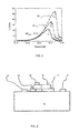
Figure 1 shows the trade-off between breakdown voltage and frequency of different high-voltage devices such as a SiGe heterojunction bipolar transistors (HBTs); -
Figure 2 shows a first example in which the semiconductor device comprises a bipolar transistor structure to which the invention can be applied; -
Figure 3 shows how the accumulation layer under a collector field plate changes with various gate voltages at the ON state; -
Figure 4 shows the value of a transistor current as a function of the applied voltage at various values of the field plate voltage; -
Figure 5 shows an adjustable relationship between frequency and breakdown voltage with varied field-plate voltages; -
Figure 6 shows how dynamic switching of the field-plate allows to use a different load line which is more in favour for better power operation; and -
Figure 7 shows an example of how to implement dynamic or real-time field plate voltage control in a power amplifier for a semiconductor device comprising a bipolar transistor. - The invention provides a circuit comprising a semiconductor device, which may, in one embodiment, comprise a transistor such as a bipolar transistor. In the following examples the semiconductor device comprises a bipolar transistor having one or more gate terminals for dynamically controlling the electric field in a collector region of the transistor in real time. The bias voltage or voltages applied to the gate terminal or terminals are dynamically controlled to achieve different transistor characteristics based on a time varying variable of the circuit. It will be appreciated that the invention has application to other types of transistor, such as MOS-type transistors (e.g. LDMOS, EDMOS etc) and diodes.
- In one example not forming part of the invention the control is static, so that different identical transistors in a circuit can have different (fixed) characteristics. In another example in accordance with the invention, a feedback circuit dynamically controls a bias voltage applied to the field gate terminal in dependence on an output voltage or collector-emitter voltage or an input voltage or base-emitter voltage of the transistor. This enables the transistor performance to be tuned in real time to the dynamically varying collector voltages (i.e. electric fields) or load requirements.
- High-voltage devices (such as Bipolar (or heterojunction bipolar) transistors) are currently used for RF power amplifiers at high frequencies thanks to their good RF characteristics. For such applications, a high-breakdown device is usually preferred allowing high voltage swing at the output (for high output power). However, high voltage devices usually have their limitations, which include:
- (i) A low speed. There is always a trade-off between breakdown voltage and speed: a high-breakdown voltage device has a low fT (the frequency at which the current gain is unity) and vice versa.
Figure 1 shows a general example of such a trade-off and shows different devices of different breakdown voltages, such as collector emitter breakdown voltage (BVceo). - (ii) Current limitations. As can be seen
Figure 1 , there is a relation between speed (fT) and maximum current (i.e. current at peak fT). This current is shown as JMAX. It means that the high-voltage device suffers also from a lower JMAX, which makes the power capability of the device also lower. - In practice, different breakdown voltages and fT values for different application requirements are obtained by changing the process for the drift region or, in the case of a bipolar transistor, the collector profile (i.e. implantation dose, implementation energy, diffusion time and temperature). This complicates the process or increases its cost and limits the flexibility of the designer in implementing ICs.
- As mentioned above, it has been proposed to use one or more gate biases to increase the flexibility and power capability for power devices.
- This invention will be described in connection with a particular bipolar transistor design which will now be described. The invention is however not limited to the particular transistor shown.
-
Figure 2 shows one example of bipolar transistor structure to which the invention can be applied. The method of the invention of using an extra terminal (for example to dynamically extend the power capability of the device in real-time) can be applied to any device provided there is a terminal or field plate that is coupled to the drift region of the device for modification of the field. The structure ofFigure 2 is one example. - The transistor has an emitter E, a base B and a collector C. The emitter E is formed in the bulk of the substrate of the device. The emitter E could also be formed as a layer above the surface of the substrate.
- The base B is provided as a layer of semiconductor material over the emitter E. The layer forming the base B can be deposited and patterned using standard lithographic techniques, to provide the desired dimensions and alignment with respect to the emitter E. The collector C can also be provided as a patterned layer of semiconductor material, dimensioned and aligned with respect to the base as desired.
- In the example structure of
Figure 2 , the collector C extends laterally in a plane substantially parallel to the major surface of the substrate. The collector C overlaps the base B (thereby to make contact therewith), but also extends past an edge of the base B and away from the overlapping region. To prevent a short circuit of the base B a dielectric 10 is provided beneath the overhang portion of the collector C to ensure that this portion of the collector C does not make contact with the emitter E. The collector C is formed at the "top" of the device (i.e. above the emitter E and the base B). The emitter E, base B and collector C are each provided with corresponding emitter contact(s) 12, base contact(s) 14 and collector contact(s) 16 The collector C is provided with a field gate comprisingcollector gate 18. - The purpose of the
collector gate 18 is to shape the electric field within the collector C. The collector gate is thus a field gate terminal of the device, in addition to the conventional base, emitter and collector terminals. It functions as a field plate. In this way, the peak electric field within the collector C can be dynamically suppressed, thereby improving still further the breakdown voltage of the device. This field shaping in this device thus makes use of a collector gate in a bottom-up bipolar transistor having a lateral collector. - Although a small gate is shown schematically in
Figure 2 , in principle the gate can also be extended laterally over the entire collector region. This can give improved field shaping. It will be appreciated that any other field-plate configuration can be included. - This invention relates to biasing of the field gate, and it can be applied to different transistor designs, such as vertical transistors. It can be applied to any structure which implements a field gate to enable field shaping in the drift region.
- In high-power devices, it is known that a field plate can be used to reshape the field distribution. With a suitable bias, an accumulation layer can be formed under the field plate, which can be used for enhancing fT and current.
- In order to understand the behaviour of the accumulation layer under different field plate bias (VG) for the field plated-collector of
Figure 2 a CAD model has been used. - The impact of field plate voltage has then been investigated at ON and OFF states:
- In the ON state (for example: VCE = 1V, VBE = 0.7V): when VG increases from 1V to 10V, the accumulation layer under the field plate starts to increase and extend under the whole field plate (to a saturation level).
Figure 3 shows how the accumulation layer under the field plate (at X=-0.5µm) changes with various gate voltages at the ON state. This accumulation layer can be considered as a thin collector (i.e., virtually moving the collector closer to the base), which helps delay the onset of the Kirk effect and increase fT. In brief, high fr and low BVceo are obtained at high VG. - In the OFF state (VCE = 1V, VBE = low voltage for example 0V): when VG increases from 1V to 10V, the breakdown BVcbo is reduced, which can be explained as follows. At a low VG and high VCE, the field is pushed away from the base-collector junction (or lines of equi-potential are pushed further to the end of collector), which is beneficial for a high breakdown. When VG is increased, that effect is reduced (e.g. the collector is depleted slower) which makes the breakdown voltage lower.
Figure 4 shows the value of BVcbo at various values of the field plate voltage VG. (VG = 1, 4, 7, 10 V). - The transistor has two main important figures of merit: breakdown voltages (BVcbo) and cut-off frequency (fT). While BVcbo is determined at the OFF-state condition, fT is determined at ON-state condition. In a method which dynamically changes breakdown voltages (BV) and Ft in real-time, an analysis of the effect of bias at these ON and OFF states is relevant. The bias conditions mentioned above for ON and OFF states (e.g., VCE=1V, VBE=0.7V; VCE=1V, VBE=0V) are of course simply a typical example of biasing for a silicon-based bipolar transistor. Other bias conditions are possible.
- There are various applications of this control of the accumulation layer.
- A first application is to create a single design of device with various values of fT and breakdown voltage. This can be considered to be a static implementation not forming part of the invention, in which different transistors in a multiple-transistor circuit are biased to provide different transistor characteristics.
- By making use of the effect described above relating to the accumulation layer, one device can be made with an fT and breakdown (BVceo and BVcbo), which can be adjusted by varying only the field-plate bias.
-
Figure 5 shows an adjustable fr /BVceo with varied field-plate voltages. - As shown in
Figure 5 , by increasing VG from 1V to 7V, BVceo is reduced from 9.5V to 5V; and then fr increases from 20 to 32 GHz. - This shows that depending on the gate biasing it is possible to trade-off fT with BV (most clearly seen in
Figure 5b) . - By adapting the gate voltage, the breakdown voltage and fT and fMAX can be adapted (with fT and fMAX going up when BV is going down). As such, the same design of device can be used either as a lower-frequency-higher-voltage device or as a high-frequency-lower-voltage device.
- In the static implementation, a DC bias is applied to the gate which can be a single gate or a gate which is by split into parts. One or more gates can be used for optimal field shaping. A gate part closer to the base-collector junction can be used to shape the field for control of the breakdown. Different gates can be provided with different static bias levels.
- A designer can have more flexibility to apply a given transistor type to the desired application. If it is a wireless infrastructure application, the supply voltages can be as high as 5V or 9V, while frequency bands are 900MHz, 2.1 GHz, 2.4 GHz, 3.5 GHz and 5.8GHz.
- In this way, separate technologies are no longer needed for different frequency bands - for example, one for frequencies below 2.7GHz and another for frequencies above 2.7GHz.
- In summary, the technology using gated devices such as the HBT of the example can cover:
- (i) High gain at different frequency bands (wide band design) at a fixed breakdown.
- (ii) High linearity over frequency and wide band (because of high fr) by using negative feedback designs with high loop gain.
- (iii) The field-plated device can be universal for different applications. Depending on application requirements, it can be used with high supply voltages to obtain high linearity, power levels or efficiency.
- (iv) More design flexibility is provided, as the field-plated device can be used with different VG, which is dependent on the design topology.
- A further application in accordance with the invention is to enable selection of a particular load line for devices in a dynamic or real time way based on a time varying signal of the circuit.
- The power capability (and also linearity) of power amplifiers is determined by the maximum voltage (e.g. BVceo or BVcbo in a bipolar transistor) and maximum current.
-
Figure 6 shows how the load line can be shifted by biasing the field-plate in real-time (at the same speed as collector). - The desired load line can be selected by the dynamic switching approach. With a better load line, better linearity, output power or efficiency can be obtained as well.
- This means that in a first region (shown as Region I), where a high breakdown is needed, a small VG is applied and a high reliable breakdown voltage (such as BVceo and also BVcbo) can be obtained. In a second region (shown as Region II), where a high current is needed, a large VG is applied (breakdown is not important here).
-
Figure 6 shows twoload lines - The biasing does not change the load line, instead the load line is a choice made by the designer.
- Starting with a given transistor, the designer chooses a load which fits the requirements and generates enough power and linearity. This means that the loadline is fixed and determined by the load impedance,
e.g. loadline 30. However, to have improved performance (e.g. more power) the designer would like to use a different load impedance to end up with theloadline 32, but theloadline 32 crosses the breakdown voltage limit (V,MAX on x axis) and the maximum current (JMAX on y axis). - The dynamic real-time control of the invention enables the designer not to be contrained by the maximum voltage and maximum current, so that a load impedance can be used that gives
loadline 32, even if the breakdown voltage or maximum current of the transistor is lower than the corresponding V,MAX and JMAX. The transistor can be tuned to allow more current or voltage if the transistor is kept in the correct position on the loadline. - In a standard transistor, the designer can only use
load line 30 because of the maximum V,max and Jmax values. - The dynamic real-time biasing approach enables the designer to use
load line 32 because with the circuit operated with the correct dynamic biasing, both V,max and Jmax will shift, and the transistor will adapt its point of operation in real time to remain at a suitable point on the selected loadline. - The power and linearity performance of power amplifiers is limited by Jmax and V,max (of the transistor). The invention enables both Jmax and V,max to be increased. The power and linearity performance of the power amplifier by enabling the user of
load line 32 will be better than when there is only the choice ofload line 30 - This way of biasing the field plate means the power capability of the device can be extended by pushing the load line further to the right hand side, i.e. both V,MAX and I,MAX can be increased. This enhancement is a large advantage to the current status of power (high-voltage) devices, where IMAX is often traded off versus VMAX.
- This approach can be applied in mobile phone power amplifiers. Since these amplifiers are adaptively biased to get more effective current consumption and high power efficiency, VG can be regulated so that whenever the power amplifier transistor experiences a high Vout (peak-to-peak), the high output voltage can be detected and VG can be reduced in order to increase the breakdown voltage.
- Power amplifiers tend to work sometimes with a mismatch at the output, i.e. the real or imaginary parts of the load can vary. Thus the output voltage swings can increase substantially and some part of the power is reflected back to the power amplifier. Only a certain part of the power is still transmitted to the load. In this case a fast detection could set up a low VG, extend the breakdown and the transmission would be supported without any breakdown. In a power amplifier, a very high VMAX (or BVCBO in the case of a bipolar transistor) is needed, for example 3 times larger than the operating voltage, to withstand very high output voltages in some unexpected cases of mismatch. However, using a high breakdown voltage transistor just these cases, there is a consequent sacrifice of other features (e.g. high fT or Jmax). The dynamic switching method can be used with detection of the mismatch case, and immediately the gate voltage can be lowered. In this way, a higher BV can be tolerated, whereas in normal situations, we can a higher VG is used. Thus, real time control of the bias voltage is advantageous.
- An example of implementing dynamic real-time switching operation in a power amplifier is shown schematically in
Figure 7 . -
Figure 7 shows thepower transistor 40 with the field plate gate G. There are thus four device terminals: base (B), emitter (E), collector (C) and gate (G). A substrate contact is also possible, but not essential. The (complex)load 42 is connected to the collector via aDC blocking capacitor 44. The transistor base is DC biased by abias circuit 47 and the RF input is supplied through a decoupling capacitor 48. - A
choke inductor 49 is connected between the power supply line and thetransistor 40. Thechoke 49 is used for decoupling DC and AC signals. - This is just one way of operating a power transistor, many other configurations are possible and the dynamic real-time switching of the invention can again be applied.
- The gate biasing is implemented by a high-
speed inverter 46 which probes the collector-emitter voltage of the power transistor in real-time and sends this inverted signal to the gate oftransistor 40. In this way, the gate biasing is low in the case of a high VCE (region I inFigure 6 ) while it is high for low VCE (region II inFigure 6 ). Thus, the collector forms further node from which the time-varying signal is received. The base-collector voltage can also be used as the feedback parameter. - There are other ways of sensing a voltage on the transistor and feeding it to the gate. For example, the base current can be probed or the voltage swing. Since there is a relation between base and collector current and voltages, probing the base could also be used to bias the gate.
- Sensing the output signal in a real-time mode for power amplifiers at high frequencies (GHz range) has been demonstrated for example in Young-Sang Jeon et al., "High-Efficiency Power Amplifier Using Novel Dynamic Bias Switching", IEEE Transactions of Microwave Theory and Techniques, vol. 55, No. 4, April 2007 for class-E type operation.
- Other power amplifiers configurations are possible as well but have a similar way of dynamic real-time gate-biasing as shown schematically in
Figure 7 . - For example, as mentioned above, the gate can be physically split in one or more sections (i.e. more gates next to each other on the same collector region) with every section individually dynamically biased (although a subset may be static biased) depending on the application requirements or device operation.
- The invention thus provides an approach for dynamically biasing the field plate of bipolar devices to enable a dynamic real time change (i.e. adjustability) of device characteristics and their trade-off such as breakdown voltage (BVcbo/BVceo) vs. frequency (f T/fMAX ). This extends the power capability and linearity of the device by varying VG in real time, for example at the same speed as the collector-emitter voltage swing.
- It will be appreciated that the
semiconductor device 40 ofFigure 7 may comprise a MOS transistor and comprise a source terminal in place of the collector terminal, a drain terminal in place of the emitter terminal and a gate terminal in place of the base terminal. Theinvertor 46 may be configured to apply the bias signal to a field plate gate terminal to dynamically modify the electric field in the conduction channel of the transistor. In a further example thesemiconductor device 40 may comprise a diode having an anode and a cathode and a gate field plate. The DC bias 47 may not be present in this example. - Other variations to the disclosed embodiments can be understood and effected by those skilled in the art in practicing the claimed invention, from a study of the drawings, the disclosure, and the appended claims. In the claims, the word "comprising" does not exclude other elements or steps, and the indefinite article "a" or "an" does not exclude a plurality. The mere fact that certain measures are recited in mutually different dependent claims does not indicate that a combination of these measured cannot be used to advantage. Any reference signs in the claims should not be construed as limiting the scope.
Claims (15)
- A circuit, comprising:a semiconductor device with one or more field gate terminals for controlling the electric field in a drift region of the semiconductor device;a feedback circuit configured to dynamically control a bias voltage or voltages applied to the field gate terminal or terminals, with different control voltages used for different semiconductor device characteristics in real-time in response to a time-varying signal at a further node in the circuit.
- A circuit as defined in claim 1, wherein the time-varying signal comprises an input or an output of the semiconductor device.
- A circuit as defined in claim 1, wherein the semiconductor device comprises a transistor.
- A circuit as defined in claim 1, wherein the semiconductor device comprises a diode.
- A circuit as defined in claim 3, wherein the transistor comprises a bipolar transistor and comprises a base, collector and emitter terminal and the field gate terminal or terminals are configured to dynamically control the electric field in a collector region.
- A circuit as defined in claim 5, wherein the time-varying signal used by the feedback circuit to control the bias voltage comprises a collector-emitter or base-emitter voltage.
- A circuit as defined in claim 3, wherein the transistor is of MOS type and includes a source, drain and gate terminal and the field gate terminal or terminals are configured to dynamically control the electric field in a channel region of the transistor.
- A circuit as defined in claim 7, wherein the time-varying signal used by the feedback circuit to control the bias voltage comprises a source-drain voltage or a gate-source voltage.
- A circuit as claimed in any preceding claim, wherein the feedback circuit comprises an inverter connected between an output of the semiconductor device and the field gate terminal.
- A circuit as defined in any preceding claim, wherein the feedback circuit is configured to determine the bias voltage or voltages based on a time varying load mismatch signal.
- A circuit as claimed in claim 1, wherein the dynamic real-time control is at the frequency of operation of the semiconductor device or related to the frequency.
- An RF power amplifier comprising a circuit as claimed in any preceding claim.
- A method of controlling a semiconductor device comprising one or more field gate terminals for controlling the electric field in a drift region of the semiconductor device, wherein the method comprises:dynamically controlling the bias voltage or bias voltages applied to the field gate terminal or terminals to achieve different transistor characteristics in real-time in response to a time-varying signal in the circuit.
- A method as claimed in claim 13, wherein the semiconductor device comprises a bipolar transistor having a base, collector and emitter terminal and the method comprises dynamically controlling the bias voltage or voltages applied to the field gate terminal or terminals to dynamically control the electric field in a collector region in dependence on a collector-emitter or base-emitter voltage of the bipolar transistor.
- An electronic device including the circuit of any one of claims 1 to 11.
Priority Applications (2)
| Application Number | Priority Date | Filing Date | Title |
|---|---|---|---|
| US14/286,418 US9515644B2 (en) | 2013-05-23 | 2014-05-23 | Semiconductor device and circuit with dynamic control of electric field |
| EP14169718.5A EP2806460B1 (en) | 2013-05-23 | 2014-05-23 | Semiconductor device and circuit with dynamic control of electric field |
Applications Claiming Priority (2)
| Application Number | Priority Date | Filing Date | Title |
|---|---|---|---|
| EP13168935 | 2013-05-23 | ||
| EP14169718.5A EP2806460B1 (en) | 2013-05-23 | 2014-05-23 | Semiconductor device and circuit with dynamic control of electric field |
Publications (3)
| Publication Number | Publication Date |
|---|---|
| EP2806460A2 true EP2806460A2 (en) | 2014-11-26 |
| EP2806460A3 EP2806460A3 (en) | 2014-12-17 |
| EP2806460B1 EP2806460B1 (en) | 2020-01-01 |
Family
ID=48463857
Family Applications (1)
| Application Number | Title | Priority Date | Filing Date |
|---|---|---|---|
| EP14169718.5A Active EP2806460B1 (en) | 2013-05-23 | 2014-05-23 | Semiconductor device and circuit with dynamic control of electric field |
Country Status (2)
| Country | Link |
|---|---|
| US (2) | US20140347135A1 (en) |
| EP (1) | EP2806460B1 (en) |
Families Citing this family (2)
| Publication number | Priority date | Publication date | Assignee | Title |
|---|---|---|---|---|
| US10586865B2 (en) | 2017-09-29 | 2020-03-10 | Cirrus Logic, Inc. | Dual gate metal-oxide-semiconductor field-effect transistor |
| US12598768B2 (en) | 2022-07-06 | 2026-04-07 | Nxp B.V. | FinFET with gate extension |
Citations (1)
| Publication number | Priority date | Publication date | Assignee | Title |
|---|---|---|---|---|
| US6777780B2 (en) | 2001-08-07 | 2004-08-17 | Koninklijke Philips Electronics N.V. | Trench bipolar transistor |
Family Cites Families (13)
| Publication number | Priority date | Publication date | Assignee | Title |
|---|---|---|---|---|
| NL8204855A (en) * | 1982-12-16 | 1984-07-16 | Philips Nv | FIELD-EFFECT TRANSISTOR WITH INSULATED STEERING ELECTRODES AND METHOD OF MANUFACTURING THESE. |
| US4868921A (en) * | 1986-09-05 | 1989-09-19 | General Electric Company | High voltage integrated circuit devices electrically isolated from an integrated circuit substrate |
| US6140877A (en) * | 1998-12-11 | 2000-10-31 | Micron Technology, Inc. | Low power supply CMOS differential amplifier topology |
| US6665354B1 (en) * | 1999-09-02 | 2003-12-16 | Ati International Srl | Differential input receiver and method for reducing noise |
| JP4514369B2 (en) * | 2001-07-19 | 2010-07-28 | 株式会社リコー | Semiconductor device and manufacturing method thereof |
| US6812533B2 (en) | 2002-12-24 | 2004-11-02 | International Business Machines Corporation | SOI based bipolar transistor having a majority carrier accumulation layer as subcollector |
| US20080122519A1 (en) * | 2006-06-12 | 2008-05-29 | Nowak Edward J | Method and circuits for regulating threshold voltage in transistor devices |
| US8026146B2 (en) * | 2006-08-31 | 2011-09-27 | Nxp B.V. | Method of manufacturing a bipolar transistor |
| JP2010225797A (en) | 2009-03-23 | 2010-10-07 | Ricoh Co Ltd | Semiconductor device |
| US8299578B1 (en) * | 2009-11-12 | 2012-10-30 | National Semiconductor Corporation | High voltage bipolar transistor with bias shield |
| US8482029B2 (en) * | 2011-05-27 | 2013-07-09 | Infineon Technologies Austria Ag | Semiconductor device and integrated circuit including the semiconductor device |
| CN102437180B (en) * | 2011-11-21 | 2013-09-11 | 上海华虹Nec电子有限公司 | Ultra high voltage silicon germanium heterojunction bipolar transistor (HBT) device and manufacturing method thereof |
| EP2784822B1 (en) | 2013-03-25 | 2018-12-19 | Nxp B.V. | Collector-up bipolar transistor and method of manufacturing the same |
-
2014
- 2014-05-22 US US14/284,509 patent/US20140347135A1/en not_active Abandoned
- 2014-05-23 US US14/286,418 patent/US9515644B2/en active Active
- 2014-05-23 EP EP14169718.5A patent/EP2806460B1/en active Active
Patent Citations (1)
| Publication number | Priority date | Publication date | Assignee | Title |
|---|---|---|---|---|
| US6777780B2 (en) | 2001-08-07 | 2004-08-17 | Koninklijke Philips Electronics N.V. | Trench bipolar transistor |
Non-Patent Citations (1)
| Title |
|---|
| YOUNG-SANG JEON ET AL.: "High-Efficiency Power Amplifier Using Novel Dynamic Bias Switching", IEEE TRANSACTIONS OF MICROWAVE THEORY AND TECHNIQUES, vol. 55, no. 4, April 2007 (2007-04-01) |
Also Published As
| Publication number | Publication date |
|---|---|
| EP2806460B1 (en) | 2020-01-01 |
| US9515644B2 (en) | 2016-12-06 |
| EP2806460A3 (en) | 2014-12-17 |
| US20140347135A1 (en) | 2014-11-27 |
| US20140347131A1 (en) | 2014-11-27 |
Similar Documents
| Publication | Publication Date | Title |
|---|---|---|
| US10263577B2 (en) | Gate drive circuit and method of operating the same | |
| US8536931B2 (en) | BI-FET cascode power switch | |
| KR20070116115A (en) | Electronic RF device and its manufacturing method | |
| EP3314758A1 (en) | Bootstrap class-d wideband rf power amplifier | |
| Alekseev et al. | DC and high-frequency performance of AlGaN/GaN Heterojunction Bipolar Transistors | |
| US9515644B2 (en) | Semiconductor device and circuit with dynamic control of electric field | |
| CN113257887A (en) | 4H-SiC metal semiconductor field effect transistor with three regions | |
| Koudymov et al. | Monolithically integrated high-power broad-band RF switch based on III-N insulated gate transistors | |
| CN107768441B (en) | Vertical double-gate field effect transistor and self-clamping breakdown-preventing radio frequency amplifier | |
| Tsai | CMOS power amplifiers for wireless communications | |
| JP2006279316A (en) | Switch circuit device | |
| Weng et al. | Minimum Power Input Control for Class-E Amplifier Using Depletion-Mode Gallium Nitride High Electron Mobility Transistor. Energies 2021, 14, 2302 | |
| Dellsperger | Device Evaluation for Current-Mode Class-D RF Power Amplifiers | |
| CN100563096C (en) | Linear bias circuit with adaptability | |
| Stamper et al. | High-resistivity SiGe BiCMOS technology development | |
| US20260012173A1 (en) | Bidirectional switch driver | |
| Muller et al. | LDMOSFET and SiGe: C HBT integrated in a 0.25/spl mu/m BiCMOS technology for RF-PA applications | |
| US11881823B2 (en) | Power amplifier circuit | |
| WO2008083128A1 (en) | Two-stage amplification using intermediate non-linear square wave | |
| Kassmi et al. | PSPICE model of the power LDMOS transistor for radio frequency applications in the 1.8–2.2 GHz Band | |
| Medina | RF power amplifiers for wireless communications | |
| Banerjee | Designing Transistors for Specific Applications | |
| Kashif | Optimization of LDMOS Transistor in Power Amplifiers for Communication Systems | |
| Inoue et al. | MMIC technologies for MW and MMW applications | |
| Snowden | Recent developments in compound semiconductor microwave power transistor technology |
Legal Events
| Date | Code | Title | Description |
|---|---|---|---|
| PUAL | Search report despatched |
Free format text: ORIGINAL CODE: 0009013 |
|
| PUAI | Public reference made under article 153(3) epc to a published international application that has entered the european phase |
Free format text: ORIGINAL CODE: 0009012 |
|
| 17P | Request for examination filed |
Effective date: 20140523 |
|
| AK | Designated contracting states |
Kind code of ref document: A2 Designated state(s): AL AT BE BG CH CY CZ DE DK EE ES FI FR GB GR HR HU IE IS IT LI LT LU LV MC MK MT NL NO PL PT RO RS SE SI SK SM TR |
|
| AX | Request for extension of the european patent |
Extension state: BA ME |
|
| AK | Designated contracting states |
Kind code of ref document: A3 Designated state(s): AL AT BE BG CH CY CZ DE DK EE ES FI FR GB GR HR HU IE IS IT LI LT LU LV MC MK MT NL NO PL PT RO RS SE SI SK SM TR |
|
| AX | Request for extension of the european patent |
Extension state: BA ME |
|
| RIC1 | Information provided on ipc code assigned before grant |
Ipc: H01L 29/40 20060101AFI20141113BHEP Ipc: H03F 3/20 20060101ALI20141113BHEP Ipc: H01L 29/732 20060101ALI20141113BHEP |
|
| R17P | Request for examination filed (corrected) |
Effective date: 20150617 |
|
| RBV | Designated contracting states (corrected) |
Designated state(s): AL AT BE BG CH CY CZ DE DK EE ES FI FR GB GR HR HU IE IS IT LI LT LU LV MC MK MT NL NO PL PT RO RS SE SI SK SM TR |
|
| 17Q | First examination report despatched |
Effective date: 20160926 |
|
| STAA | Information on the status of an ep patent application or granted ep patent |
Free format text: STATUS: EXAMINATION IS IN PROGRESS |
|
| GRAP | Despatch of communication of intention to grant a patent |
Free format text: ORIGINAL CODE: EPIDOSNIGR1 |
|
| STAA | Information on the status of an ep patent application or granted ep patent |
Free format text: STATUS: GRANT OF PATENT IS INTENDED |
|
| INTG | Intention to grant announced |
Effective date: 20190923 |
|
| RIN1 | Information on inventor provided before grant (corrected) |
Inventor name: SLOTBOOM, JAN WILLEM Inventor name: HERINGA, ANCO Inventor name: VANHOUCKE, TONY Inventor name: GRIDELET, EVELYNE Inventor name: ZAHARIEV, IVAN Inventor name: HURKX, GODEFRIDUS ANTONIUS MARIA Inventor name: DINH, VIET THANH |
|
| GRAS | Grant fee paid |
Free format text: ORIGINAL CODE: EPIDOSNIGR3 |
|
| GRAA | (expected) grant |
Free format text: ORIGINAL CODE: 0009210 |
|
| STAA | Information on the status of an ep patent application or granted ep patent |
Free format text: STATUS: THE PATENT HAS BEEN GRANTED |
|
| AK | Designated contracting states |
Kind code of ref document: B1 Designated state(s): AL AT BE BG CH CY CZ DE DK EE ES FI FR GB GR HR HU IE IS IT LI LT LU LV MC MK MT NL NO PL PT RO RS SE SI SK SM TR |
|
| REG | Reference to a national code |
Ref country code: GB Ref legal event code: FG4D |
|
| REG | Reference to a national code |
Ref country code: AT Ref legal event code: REF Ref document number: 1220878 Country of ref document: AT Kind code of ref document: T Effective date: 20200115 Ref country code: CH Ref legal event code: EP |
|
| REG | Reference to a national code |
Ref country code: IE Ref legal event code: FG4D |
|
| REG | Reference to a national code |
Ref country code: DE Ref legal event code: R096 Ref document number: 602014059180 Country of ref document: DE |
|
| REG | Reference to a national code |
Ref country code: NL Ref legal event code: MP Effective date: 20200101 |
|
| REG | Reference to a national code |
Ref country code: LT Ref legal event code: MG4D |
|
| PG25 | Lapsed in a contracting state [announced via postgrant information from national office to epo] |
Ref country code: LT Free format text: LAPSE BECAUSE OF FAILURE TO SUBMIT A TRANSLATION OF THE DESCRIPTION OR TO PAY THE FEE WITHIN THE PRESCRIBED TIME-LIMIT Effective date: 20200101 Ref country code: PT Free format text: LAPSE BECAUSE OF FAILURE TO SUBMIT A TRANSLATION OF THE DESCRIPTION OR TO PAY THE FEE WITHIN THE PRESCRIBED TIME-LIMIT Effective date: 20200527 Ref country code: CZ Free format text: LAPSE BECAUSE OF FAILURE TO SUBMIT A TRANSLATION OF THE DESCRIPTION OR TO PAY THE FEE WITHIN THE PRESCRIBED TIME-LIMIT Effective date: 20200101 Ref country code: RS Free format text: LAPSE BECAUSE OF FAILURE TO SUBMIT A TRANSLATION OF THE DESCRIPTION OR TO PAY THE FEE WITHIN THE PRESCRIBED TIME-LIMIT Effective date: 20200101 Ref country code: FI Free format text: LAPSE BECAUSE OF FAILURE TO SUBMIT A TRANSLATION OF THE DESCRIPTION OR TO PAY THE FEE WITHIN THE PRESCRIBED TIME-LIMIT Effective date: 20200101 Ref country code: NO Free format text: LAPSE BECAUSE OF FAILURE TO SUBMIT A TRANSLATION OF THE DESCRIPTION OR TO PAY THE FEE WITHIN THE PRESCRIBED TIME-LIMIT Effective date: 20200401 Ref country code: NL Free format text: LAPSE BECAUSE OF FAILURE TO SUBMIT A TRANSLATION OF THE DESCRIPTION OR TO PAY THE FEE WITHIN THE PRESCRIBED TIME-LIMIT Effective date: 20200101 |
|
| PG25 | Lapsed in a contracting state [announced via postgrant information from national office to epo] |
Ref country code: GR Free format text: LAPSE BECAUSE OF FAILURE TO SUBMIT A TRANSLATION OF THE DESCRIPTION OR TO PAY THE FEE WITHIN THE PRESCRIBED TIME-LIMIT Effective date: 20200402 Ref country code: IS Free format text: LAPSE BECAUSE OF FAILURE TO SUBMIT A TRANSLATION OF THE DESCRIPTION OR TO PAY THE FEE WITHIN THE PRESCRIBED TIME-LIMIT Effective date: 20200501 Ref country code: BG Free format text: LAPSE BECAUSE OF FAILURE TO SUBMIT A TRANSLATION OF THE DESCRIPTION OR TO PAY THE FEE WITHIN THE PRESCRIBED TIME-LIMIT Effective date: 20200401 Ref country code: LV Free format text: LAPSE BECAUSE OF FAILURE TO SUBMIT A TRANSLATION OF THE DESCRIPTION OR TO PAY THE FEE WITHIN THE PRESCRIBED TIME-LIMIT Effective date: 20200101 Ref country code: HR Free format text: LAPSE BECAUSE OF FAILURE TO SUBMIT A TRANSLATION OF THE DESCRIPTION OR TO PAY THE FEE WITHIN THE PRESCRIBED TIME-LIMIT Effective date: 20200101 Ref country code: SE Free format text: LAPSE BECAUSE OF FAILURE TO SUBMIT A TRANSLATION OF THE DESCRIPTION OR TO PAY THE FEE WITHIN THE PRESCRIBED TIME-LIMIT Effective date: 20200101 |
|
| REG | Reference to a national code |
Ref country code: DE Ref legal event code: R097 Ref document number: 602014059180 Country of ref document: DE |
|
| PG25 | Lapsed in a contracting state [announced via postgrant information from national office to epo] |
Ref country code: EE Free format text: LAPSE BECAUSE OF FAILURE TO SUBMIT A TRANSLATION OF THE DESCRIPTION OR TO PAY THE FEE WITHIN THE PRESCRIBED TIME-LIMIT Effective date: 20200101 Ref country code: SM Free format text: LAPSE BECAUSE OF FAILURE TO SUBMIT A TRANSLATION OF THE DESCRIPTION OR TO PAY THE FEE WITHIN THE PRESCRIBED TIME-LIMIT Effective date: 20200101 Ref country code: DK Free format text: LAPSE BECAUSE OF FAILURE TO SUBMIT A TRANSLATION OF THE DESCRIPTION OR TO PAY THE FEE WITHIN THE PRESCRIBED TIME-LIMIT Effective date: 20200101 Ref country code: ES Free format text: LAPSE BECAUSE OF FAILURE TO SUBMIT A TRANSLATION OF THE DESCRIPTION OR TO PAY THE FEE WITHIN THE PRESCRIBED TIME-LIMIT Effective date: 20200101 Ref country code: SK Free format text: LAPSE BECAUSE OF FAILURE TO SUBMIT A TRANSLATION OF THE DESCRIPTION OR TO PAY THE FEE WITHIN THE PRESCRIBED TIME-LIMIT Effective date: 20200101 Ref country code: RO Free format text: LAPSE BECAUSE OF FAILURE TO SUBMIT A TRANSLATION OF THE DESCRIPTION OR TO PAY THE FEE WITHIN THE PRESCRIBED TIME-LIMIT Effective date: 20200101 |
|
| PLBE | No opposition filed within time limit |
Free format text: ORIGINAL CODE: 0009261 |
|
| STAA | Information on the status of an ep patent application or granted ep patent |
Free format text: STATUS: NO OPPOSITION FILED WITHIN TIME LIMIT |
|
| REG | Reference to a national code |
Ref country code: AT Ref legal event code: MK05 Ref document number: 1220878 Country of ref document: AT Kind code of ref document: T Effective date: 20200101 |
|
| 26N | No opposition filed |
Effective date: 20201002 |
|
| PG25 | Lapsed in a contracting state [announced via postgrant information from national office to epo] |
Ref country code: LI Free format text: LAPSE BECAUSE OF NON-PAYMENT OF DUE FEES Effective date: 20200531 Ref country code: IT Free format text: LAPSE BECAUSE OF FAILURE TO SUBMIT A TRANSLATION OF THE DESCRIPTION OR TO PAY THE FEE WITHIN THE PRESCRIBED TIME-LIMIT Effective date: 20200101 Ref country code: CH Free format text: LAPSE BECAUSE OF NON-PAYMENT OF DUE FEES Effective date: 20200531 Ref country code: MC Free format text: LAPSE BECAUSE OF FAILURE TO SUBMIT A TRANSLATION OF THE DESCRIPTION OR TO PAY THE FEE WITHIN THE PRESCRIBED TIME-LIMIT Effective date: 20200101 Ref country code: AT Free format text: LAPSE BECAUSE OF FAILURE TO SUBMIT A TRANSLATION OF THE DESCRIPTION OR TO PAY THE FEE WITHIN THE PRESCRIBED TIME-LIMIT Effective date: 20200101 |
|
| PG25 | Lapsed in a contracting state [announced via postgrant information from national office to epo] |
Ref country code: PL Free format text: LAPSE BECAUSE OF FAILURE TO SUBMIT A TRANSLATION OF THE DESCRIPTION OR TO PAY THE FEE WITHIN THE PRESCRIBED TIME-LIMIT Effective date: 20200101 Ref country code: SI Free format text: LAPSE BECAUSE OF FAILURE TO SUBMIT A TRANSLATION OF THE DESCRIPTION OR TO PAY THE FEE WITHIN THE PRESCRIBED TIME-LIMIT Effective date: 20200101 |
|
| REG | Reference to a national code |
Ref country code: BE Ref legal event code: MM Effective date: 20200531 |
|
| GBPC | Gb: european patent ceased through non-payment of renewal fee |
Effective date: 20200523 |
|
| PG25 | Lapsed in a contracting state [announced via postgrant information from national office to epo] |
Ref country code: LU Free format text: LAPSE BECAUSE OF NON-PAYMENT OF DUE FEES Effective date: 20200523 |
|
| PG25 | Lapsed in a contracting state [announced via postgrant information from national office to epo] |
Ref country code: IE Free format text: LAPSE BECAUSE OF NON-PAYMENT OF DUE FEES Effective date: 20200523 Ref country code: GB Free format text: LAPSE BECAUSE OF NON-PAYMENT OF DUE FEES Effective date: 20200523 |
|
| PG25 | Lapsed in a contracting state [announced via postgrant information from national office to epo] |
Ref country code: BE Free format text: LAPSE BECAUSE OF NON-PAYMENT OF DUE FEES Effective date: 20200531 |
|
| PG25 | Lapsed in a contracting state [announced via postgrant information from national office to epo] |
Ref country code: TR Free format text: LAPSE BECAUSE OF FAILURE TO SUBMIT A TRANSLATION OF THE DESCRIPTION OR TO PAY THE FEE WITHIN THE PRESCRIBED TIME-LIMIT Effective date: 20200101 Ref country code: MT Free format text: LAPSE BECAUSE OF FAILURE TO SUBMIT A TRANSLATION OF THE DESCRIPTION OR TO PAY THE FEE WITHIN THE PRESCRIBED TIME-LIMIT Effective date: 20200101 Ref country code: CY Free format text: LAPSE BECAUSE OF FAILURE TO SUBMIT A TRANSLATION OF THE DESCRIPTION OR TO PAY THE FEE WITHIN THE PRESCRIBED TIME-LIMIT Effective date: 20200101 |
|
| PG25 | Lapsed in a contracting state [announced via postgrant information from national office to epo] |
Ref country code: MK Free format text: LAPSE BECAUSE OF FAILURE TO SUBMIT A TRANSLATION OF THE DESCRIPTION OR TO PAY THE FEE WITHIN THE PRESCRIBED TIME-LIMIT Effective date: 20200101 Ref country code: AL Free format text: LAPSE BECAUSE OF FAILURE TO SUBMIT A TRANSLATION OF THE DESCRIPTION OR TO PAY THE FEE WITHIN THE PRESCRIBED TIME-LIMIT Effective date: 20200101 |
|
| P01 | Opt-out of the competence of the unified patent court (upc) registered |
Effective date: 20230725 |
|
| REG | Reference to a national code |
Ref country code: DE Ref legal event code: R079 Ref document number: 602014059180 Country of ref document: DE Free format text: PREVIOUS MAIN CLASS: H01L0029400000 Ipc: H10D0064000000 |
|
| PGFP | Annual fee paid to national office [announced via postgrant information from national office to epo] |
Ref country code: DE Payment date: 20250423 Year of fee payment: 12 |
|
| PGFP | Annual fee paid to national office [announced via postgrant information from national office to epo] |
Ref country code: FR Payment date: 20250423 Year of fee payment: 12 |