EP2806365A1 - Wire harness analysis device, wire harness analysis method, and wire harness analysis program - Google Patents
Wire harness analysis device, wire harness analysis method, and wire harness analysis program Download PDFInfo
- Publication number
- EP2806365A1 EP2806365A1 EP13738807.0A EP13738807A EP2806365A1 EP 2806365 A1 EP2806365 A1 EP 2806365A1 EP 13738807 A EP13738807 A EP 13738807A EP 2806365 A1 EP2806365 A1 EP 2806365A1
- Authority
- EP
- European Patent Office
- Prior art keywords
- wire harness
- wire
- fixture
- electric
- electric wires
- Prior art date
- Legal status (The legal status is an assumption and is not a legal conclusion. Google has not performed a legal analysis and makes no representation as to the accuracy of the status listed.)
- Ceased
Links
Images


Classifications
-
- G—PHYSICS
- G06—COMPUTING OR CALCULATING; COUNTING
- G06F—ELECTRIC DIGITAL DATA PROCESSING
- G06F30/00—Computer-aided design [CAD]
-
- G—PHYSICS
- G01—MEASURING; TESTING
- G01M—TESTING STATIC OR DYNAMIC BALANCE OF MACHINES OR STRUCTURES; TESTING OF STRUCTURES OR APPARATUS, NOT OTHERWISE PROVIDED FOR
- G01M99/00—Subject matter not provided for in other groups of this subclass
- G01M99/008—Subject matter not provided for in other groups of this subclass by doing functionality tests
-
- G—PHYSICS
- G06—COMPUTING OR CALCULATING; COUNTING
- G06F—ELECTRIC DIGITAL DATA PROCESSING
- G06F30/00—Computer-aided design [CAD]
- G06F30/20—Design optimisation, verification or simulation
-
- G—PHYSICS
- G06—COMPUTING OR CALCULATING; COUNTING
- G06F—ELECTRIC DIGITAL DATA PROCESSING
- G06F2113/00—Details relating to the application field
- G06F2113/16—Cables, cable trees or wire harnesses
Definitions
- the present invention relates to a wire harness analyzing device, a wire harness analyzing method and a wire harness analyzing program for analyzing a wire harness.
- penetration means that when the imaginary wire harness is modelled, the contact of an electric wire and an object except the electric wire is not considered, and the electric wire is placed as if the electric wire is buried in the object.
- An error in length may occurs since the electric wire that penetrates or is penetrated when the imaginary wire harness is modelled, may pass a course which an electric wire of the actual wire harness cannot pass.
- the present invention is made in view of the above circumstances, and the object of the present invention is to provide a wire harness analyzing device, a wire harness analyzing method and a wire harness analyzing program so that in the design stage of a wire harness, the length and shape of each of the electric wires in the wire harness, for which the electric wires are wired on a jig board, can be more accurately modelled.
- the wire harness analyzing device of the present invention is characterized by the following configurations (1) to (4).
- the wire harness analyzing device of the above (1) to (4) the wire harness analyzing method of the above (5) and the wire harness analyzing program of the above (6), in the design stage of a wire harness, the length and shape of each of the electric wires in the wire harness, for which the electric wires are wired on a jig board, can be more accurately modelled.
- the wire harness analyzing device, the wire harness analyzing method and the wire harness analyzing program of the present invention in the design stage of a wire harness, the length and shape of each of the electric wires in the wire harness, for which the electric wires are wired on a jig board, can be more accurately modelled.
- the design of the whole jig board such as the position where a fixture is arranged on the jig board or the shape of a fixture can be examined beforehand.
- wire harness analyzing device of an embodiment of the present invention and the analyzing method performed with the wire harness analyzing device are described in detail.
- FIG. 1 (a) and 1(b) are image figures of a wire harness which is modelled by using interatomic force potential, in which Fig. 1 (a) is a figure which indicates that the interatomic force potential does not act, and Fig. 1 (b) is a figure which indicates that the interatomic force potential acts.
- Fig. 2 (a) and Fig. 2 (b) are figures which indicate interaction that acts between atoms, in which Fig. 2 (a) is a figure which indicates that an attractive force acts between atoms, and Fig. 2 (b) is a figure which indicates that a repulsive force acts between atoms.
- a plurality of electric wires C1, C2 and C3 of a wire harness W/H are respectively modelled as spherical potential evaluation atoms S1, S2 and S3, which are arranged to be next to each other.
- radiuses R1, R2 and R3 of the potential evaluation atoms S1, S2 and S3 of the electric wires C1, C2 and C3 are all constant numerical values.
- the calculation algorithm that the wire harness analyzing device of the embodiment of the present invention performs uses the algorithm described in the above item [wire harness simulation technique in which stress between electric wires is considered].
- a fixture which prescribes a course along which the electric wires are wired is also modelled as a lot of spherical potential evaluation atoms which are arranged to be next to each other. In this way, an imaginary wire harness can be so modelled that the electric wires would not penetrate the fixture.
- FIG. 3 is a figure which indicates a U fork which is modelled with spherical potential evaluation atoms.
- a U fork 3 is so arranged that spherical potential evaluation atoms Uf are continuous in a U character portion 31 of a U character form.
- a supporting portion 32 of the U fork 3 which supports the U character portion 31 is arranged at a potential evaluation atom that is positioned at the bottom of the U character portion 31 so that the spherical potential evaluation atoms Uf are continuous.
- the calculation algorithm that the wire harness analyzing device of the embodiment of the present invention performs is performed as described in the above item [wire harness simulation technique in which stress between electric wires is considered] by using the potential evaluation atoms with which the electric wires are modelled and the potential evaluation atoms with which the fixture is modelled.
- Fig. 4 is a block diagram which indicates the hardware of the wire harness analyzing device of the embodiment of the present invention.
- the wire harness analyzing device of the embodiment of the present invention includes an input part 411, a database part 412, a program memory 413, a data memory 414, a display part 415, and a processing part 416.
- the input part 411 is implemented with various input interfaces such as a keyboard, a mouse, and a numeric keypad
- the database part 412 and the program memory 413 are implemented with hard disk drives (HDD)
- the data memory 414 is implemented with a RAM (Random Access Memory)
- the display part 415 is implemented with various output devices such as a CRT display or a liquid crystal display
- the processing part 416 is implemented with a CPU (Central Processing Unit).
- a CPU Central Processing Unit
- the database part 412 information about the electric wires of the wire harness and information to model the electric wires, information about connectors of the wire harness, information about the fixture which is arranged on the jig board and information to model the fixture are stored.
- the program memory 413 a program to make the processing part 416 perform the calculation algorithm described in the above-mentioned [wire harness simulation technique in which stress between an electric wire and the fixture is considered] is recorded.
- the data memory 414 data which are input into and output from the processing part 416 that performs the calculation algorithm described in the [wire harness simulation technique in which stress between an electric wire and the fixture is considered] are recorded.
- Fig. 5 is a flowchart which indicates the steps of the analyzing method performed with the wire harness analyzing device of the embodiments of the present invention.
- Step S51 the input of numerical values to model the electric wires of a wire harness and a fixture that is arranged on a jig board is received.
- numerical values related to the electric wires such as the radius of the spherical potential evaluation atoms to model the electric wires, coordinates that provide the initial values of the potential evaluation atoms to represent the initial shapes of the electric wires, and numerical values that provide the attractive forces and repulsive forces between the potential evaluation atoms to determine the stiffness of the electric wires are input.
- Step S51 numerical values related to the fixture such as the radius of the spherical potential evaluation atoms to model the fixture, coordinates that provide the initial values of the potential evaluation atoms to represent the initial shape of the fixture, and numerical values that provide the attractive forces and repulsive forces between the potential evaluation atoms to determine the stiffness of the fixture are input.
- Step S52 numerical values including the numerical values input in the Step S51 are assumed as initial values, and an operation is performed based on the calculation algorithm in which stresses that act between electric wires and between an electric wire and the fixture are considered.
- the calculation algorithm is similar to the calculation algorithm described in the above [wire harness simulation technique in which stress between electric wires is considered].
- Step S53 based on the coordinates of the potential evaluation atoms for the electric wires and the coordinates of the potential evaluation atoms for the fixture which are obtained as the result of the operation by Step S52, the electric wires which are wired on the fixture is displayed and output.
- Fig. 6 is a figure which indicates an display example of the electric wires and the U fork which are displayed and output by the wire harness analyzing device of the embodiment of the present invention. Specifically, at the coordinates of the potential evaluation atoms S1 and S2 of the electric wires C1 and C2 and the potential evaluation atoms Uf of the U fork 3, spheres having the same shape as that of the potential evaluation atoms S1, S2 and Uf are drawn.
- the plurality of electric wires C1 and C2 and the U fork 3 are drawn. Since the stress between electric wires and the stress between an electric wire and the fixture are considered for the plurality of electric wires C1 and C2 that are drawn in this way, it is prevented that one electric wire penetrates another electric wire and that an electric wire penetrates the fixture. Thereby, in the design stage of the wire harness, the length and shape of each of the electric wires in the wire harness, for which electric wires are wired on a jig board, can be more accurately modelled.
- the electric wires are viewed as a plurality of spheres which are coupled, and are not viewed as actual electric wires whose wire diameter is longitudinally constant.
- the U fork is also viewed as a plurality of spheres which are coupled, and is not viewed as an actual U fork. Therefore, for adjacent spheres in one electric wire, the gap between the adjacent spheres is supplemented by drawing a cylindrical body so that one sphere of the two spheres is located at the end surface at one side, and the other sphere is located at the end surface at the other side. If this supplementing is performed on the gaps among all the adjacent spheres in the electric wire or the U fork, as shown in dotted lines of Fig. 6 , the electric wire or the U fork is drawn into a tube shape which is close to the real shape.
- the wire harness analyzing device and the analyzing method performed with the wire harness analyzing device of the embodiment of the present invention because the stress between the electric wires and the stress between an electric wire and the fixture are considered, for the electric wires that are drawn as an analyzing result, it is prevented that one electric wire penetrates another electric wire and one electric wire penetrates the fixture.
- the length and shape of each of the electric wires in the wire harness, for which electric wires are wired on a jig board can be more accurately modelled.
- the design of the whole jig board such as the position where a fixture is arranged on the jig board or the shape of a fixture can be examined beforehand.
- a boundary condition to prevent potential evaluation atoms of an electric wire from entering into the U fork more specifically, a boundary condition to retain the potential evaluation atoms at positions where the surface of the potential evaluation atoms of the electric wire contacts the outer surface of the cylindrical body even if the potential evaluation atoms are analyzed so that the surface of the potential evaluation atoms is positioned inside the U fork is set for the outer surface of the cylindrical body.
- the boundary condition to be set when the U fork is modelled as a cylindrical body is not limited to the above.
- a boundary condition such as that one of the potential evaluation atoms of an electric wire whose distance from the U fork is the shortest is identified, and an interatomic repulsive force is generated for the potential evaluation atom based on the distance to position the potential evaluation atom may be considered.
- the fixture is also modelled with potential evaluation atoms.
- a technique for example, in which numerical values which indicate the three-dimensional shape to model the fixture are input, and based on the numerical values, the U fork is superimposed on the electric wire which is modelled with potential evaluation atoms to output the display, is considerable.
- the calculation algorithm that the wire harness analyzing device of the other embodiments of the present invention perform uses the algorithm described in the above item [wire harness simulation technique in which stress between electric wires is considered].
- various exterior components of the wire harness W such as a connector, a protector, a corrugated tube, and a resin tape are modelled with a lot of spherical potential evaluation atoms which are arranged to be next to each other. In this way, an imaginary wire harness can be so modelled that the electric wires would not penetrate the exterior components.
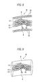
- Fig. 8 is a figure which indicates electric wires and a corrugated tube which are modelled with spherical potential evaluation atoms.
- a wall 71 which defines the tube shape of a corrugated tube 8 is so arranged that spherical potential evaluation atoms Uc are continuous.
- the calculation algorithm that the wire harness analyzing device of the other embodiments of the present invention performs is performed as described in the above item [wire harness simulation technique in which stress between electric wires is considered] by using the potential evaluation atoms with which the electric wires are modelled and the potential evaluation atoms with which the fixture is modelled.
- the wire harness analyzing device and the analyzing method performed with the wire harness analyzing device of the other embodiments of the present invention because the stress between the electric wires, the stress between an electric wire and the fixture and the stress between an electric wire and an exterior component are considered, for the electric wires that are drawn as an analyzing result, it is prevented that one electric wire penetrates another electric wire, one electric wire penetrates the fixture and one electric wire penetrates the exterior component.
- the length and shape of each of the electric wires in the wire harness, for which electric wires are wired on a jig board can be more accurately modelled.
- the design of the whole jig board such as the position where a fixture is arranged on the jig board or the shape of a fixture can be examined beforehand.
- the corrugated tube which is an exterior component
- the whole corrugated tube is modelled.
- the corrugated tube which is an exterior component
- the corrugated tube 8 is modelled as a cylindrical body having a certain radius around the center line of the corrugated tube.
- a boundary condition to prevent potential evaluation atoms of an electric wire from entering the space outside the corrugated tube more specifically, a boundary condition to retain the potential evaluation atoms at positions where the surface of the potential evaluation atoms of the electric wire contacts the inner surface of the cylindrical body even if the potential evaluation atoms are analyzed so that the surface of the potential evaluation atoms is positioned outside the corrugated tube is set for the inner surface of the cylindrical body.
- the boundary condition to be set when the corrugated tube is modelled as a cylindrical body is not limited to the above.
- a boundary condition such as that one of the potential evaluation atoms of an electric wire whose distance from the corrugated tube is the shortest is identified, and an interatomic repulsive force is generated for the potential evaluation atom based on the distance to position the potential evaluation atom may be considered.
- the present invention relates to a wire harness analyzing device, a wire harness analyzing method and a wire harness analyzing program for analyzing a wire harness, and an effect is achieved which is that, in the design stage of the wire harness, the length and shape of each of the electric wires in the wire harness, for which the electric wires are wired on a jig board, can be more accurately modelled.
Landscapes
- Engineering & Computer Science (AREA)
- Physics & Mathematics (AREA)
- Theoretical Computer Science (AREA)
- General Physics & Mathematics (AREA)
- Computer Hardware Design (AREA)
- Evolutionary Computation (AREA)
- Geometry (AREA)
- General Engineering & Computer Science (AREA)
- Installation Of Indoor Wiring (AREA)
- Testing Of Short-Circuits, Discontinuities, Leakage, Or Incorrect Line Connections (AREA)
- Architecture (AREA)
- Software Systems (AREA)
Abstract
Description
- The present invention relates to a wire harness analyzing device, a wire harness analyzing method and a wire harness analyzing program for analyzing a wire harness.
- Before an actual wire harness is manufactured, an imaginary wire harness is modelled in a computer, and examination is made on the imaginary wire harness in a design stage. Examples of this kind of simulation are disclosed in
patent documents 1 to 4. -
- Patent document 1: Japan Patent Publication No.
8-180747 - Patent document 2: Japan Patent Publication No.
2003-132102 - Patent document 3: Japan Patent Publication No.
2009-181746 - Patent document 4: Japan Patent Publication No.
2010-49591 - If the examination is made with the above simulation in the design stage, it is required that the difference in shape or property between the actual wire harness and the imaginary wire harness is minimized. Particularly, to lower an error caused in the length of an electric wire of the wire harness, it is necessary to model the imaginary wire harness so that an electric wire in a bunch of electric wires will not penetrate other electric wires. In the present specification, "penetration" means that when the imaginary wire harness is modelled, the contact of an electric wire and an object except the electric wire is not considered, and the electric wire is placed as if the electric wire is buried in the object. An error in length may occurs since the electric wire that penetrates or is penetrated when the imaginary wire harness is modelled, may pass a course which an electric wire of the actual wire harness cannot pass.
- Furthermore, in recent years, in the process of manufacturing a wire harness, to improve the operation efficiency of wiring electric wires on a jig board, in the design stage of the wire harness, the wire harness for which electric wires are wired on the jig board is modelled (refer to a
patent document 2.). Even when the wire harness for which electric wires are wired on a jig board is modelled, to reduce an error that occurs in the length of an electric wire of the wire harness, it is necessary to model the imaginary wire harness so that an electric wire would not penetrate a fixture, such as a U fork, which prescribes a course along which the electric wire is wired. - The present invention is made in view of the above circumstances, and the object of the present invention is to provide a wire harness analyzing device, a wire harness analyzing method and a wire harness analyzing program so that in the design stage of a wire harness, the length and shape of each of the electric wires in the wire harness, for which the electric wires are wired on a jig board, can be more accurately modelled.
- In order to attain the above aim, the wire harness analyzing device of the present invention is characterized by the following configurations (1) to (4).
- (1) A wire harness analyzing device which analyzes a wire harness wired on a jig board includes an input means that receives the input of numerical values to model electric wires of the wire harness and a fixture which is arranged on the jig board and which makes it possible to wire the wire harness on the jig board, and an output means that displays the electric wire which is wired on the fixture based on information related to the electric wire which is obtained as the result of an operation based on an algorithm using values including the numerical values input into the input means as initial values to prevent penetration between electric wires and penetration between an electric wire and the fixture.
- (2) In the wire harness analyzing device according to the configuration (1), wherein the output means displays the electric wire which is wired on the fixture based on information related to the electric wire which is obtained as the result of an operation based on an algorithm using the values including the numerical values input into the input means as the initial values and considering stress that acts between electric wires and stress that acts between an electric wire and the fixture.
- (3) The wire harness analyzing device according to the configuration (1) further includes an exterior component, wherein the input means receives the input of numerical values to model the electric wires and the exterior component of the wire harness, and the output means displays the electric wire which is wired on the fixture based on information related to the electric wire which is obtained as the result of an operation based on an algorithm using the values including the numerical values input into the input means as the initial values to prevent penetration between electric wires, penetration between an electric wire and the fixture, and penetration between an electric wire and the exterior component.
- (4) In the wire harness analyzing device according to the configuration (3), the output means displays the electric wire which is wired on the fixture based on information related to the electric wire which is obtained as the result of an operation based on an algorithm using the values including the numerical values input into the input means as the initial values and considering stress that acts between electric wires, stress that acts between an electric wire and the fixture and stress that acts between an electric wire and the exterior component.
In order to attain the above aim, the wire harness analyzing method of the present invention is characterized by the following configuration (5). - (5) A wire harness analyzing method which analyzes a wire harness wired on a jig board includes an input step to input numerical values to model electric wires of the wire harness and a fixture which is arranged on the jig board and which makes it possible to wire the wire harness on the jig board, an operation step to perform an operation based on an algorithm using values including the numerical values input in the input step as initial values and considering stress that acts between electric wires and stress that acts between an electric wire and the fixture, and an output step to display the electric wire which is wired on the fixture based on information related to the electric wire which is obtained as the result of the operation in the operation step.
In order to attain the above aim, the wire harness analyzing program of the present invention is characterized by the following configuration (6). - (6) A wire harness analyzing program causing a computer to execute the steps of the wire harness analyzing method according to the configuration (5).
- According to the wire harness analyzing device of the above (1) to (4), the wire harness analyzing method of the above (5) and the wire harness analyzing program of the above (6), in the design stage of a wire harness, the length and shape of each of the electric wires in the wire harness, for which the electric wires are wired on a jig board, can be more accurately modelled.
- According to the wire harness analyzing device, the wire harness analyzing method and the wire harness analyzing program of the present invention, in the design stage of a wire harness, the length and shape of each of the electric wires in the wire harness, for which the electric wires are wired on a jig board, can be more accurately modelled. As a result, because the course along which an electric wire is wired on the jig board becomes nearer to the course that the electric wire of the actual wire harness follows, the design of the whole jig board such as the position where a fixture is arranged on the jig board or the shape of a fixture can be examined beforehand.
- The present invention has been briefly described above. Further, details of the invention will become more apparent after embodiments of the invention described below (hereinafter referred to as "embodiments") are read with reference to the accompanying figures.
-
-
Figs. 1 (a) and 1 (b) are image figures of a wire harness which is modelled by using interatomic force potential, in whichFig. 1 (a) is a figure which indicates that the interatomic force potential does not act, andFig. 1 (b) is a figure which indicates that the interatomic force potential acts. -
Fig. 2 (a) and Fig. 2 (b) are figures which indicate interaction that acts between atoms, in whichFig. 2 (a) is a figure which indicates that an attractive force acts between atoms, andFig. 2 (b) is a figure which indicates that a repulsive force acts between atoms. -
Fig. 3 is a figure which indicates a U fork which is modelled with spherical potential evaluation atoms. -
Fig. 4 is a block diagram which indicates the hardware of a wire harness analyzing device of an embodiment of the present invention. -
Fig. 5 is a flowchart which indicates the steps of an analyzing method that is performed with the wire harness analyzing device of the embodiment of the present invention. -
Fig. 6 is a figure which indicates a display example of electric wires and a U fork which are displayed and output by the wire harness analyzing device of the embodiment of the present invention. -
Fig. 7 is a figure which indicates a U fork which is modelled into a cylindrical shape. -
Fig. 8 is a figure which indicates electric wires and a corrugated tube which are modelled with spherical potential evaluation atoms. -
Fig. 9 is a figure which indicates a corrugated tube which is modelled into a cylindrical shape. - Next, the wire harness analyzing device of an embodiment of the present invention and the analyzing method performed with the wire harness analyzing device are described in detail.
- While the embodiment of the present invention is described, first, a wire harness simulation technique to prevent penetration between electric wires is described.
- An algorithm to prevent penetration between electric wires of a wire harness is fundamentally studied in "a fundamental study on wire harness simulation technique using interatomic force potential by Takei Amane, Matsushima Motoi, Komiya Shigeru and Yamamoto Ichiro, Japan Society of Mechanical Engineers Computational Mechanics Conference Proceedings". In this non-patent document, when a wire harness is designed with CAD, as a technique to consider the stiffness of the wire and to prevent penetration between wires, by considering interatomic force potential, a mathematics model to prevent penetration between wires and a calculation algorithm of the mathematics model are proposed, which is new to dynamics models suggested so far. The abstract of the calculation algorithm is described as follows.
Figs. 1 (a) and 1(b) are image figures of a wire harness which is modelled by using interatomic force potential, in whichFig. 1 (a) is a figure which indicates that the interatomic force potential does not act, andFig. 1 (b) is a figure which indicates that the interatomic force potential acts.Fig. 2 (a) and Fig. 2 (b) are figures which indicate interaction that acts between atoms, in whichFig. 2 (a) is a figure which indicates that an attractive force acts between atoms, andFig. 2 (b) is a figure which indicates that a repulsive force acts between atoms. For more information about the calculation algorithm, see the above non-patent document. - As shown in
Figs. 1 (a) and 1 (b) , a plurality of electric wires C1, C2 and C3 of a wire harness W/H are respectively modelled as spherical potential evaluation atoms S1, S2 and S3, which are arranged to be next to each other. To model the electric wires C1, C2 and C3 so that the wire diameter is longitudinally constant, radiuses R1, R2 and R3 of the potential evaluation atoms S1, S2 and S3 of the electric wires C1, C2 and C3 are all constant numerical values. - As shown in
Fig. 2 (a) , for the two potential evaluation atoms s1 and s2, if a distance d between the centers of the potential evaluation atoms s1 and s2 is bigger than the sum of the radius r1 of the potential evaluation atom s1 and the radius r2 of the potential evaluation atom s2, an attractive force acts on the two potential evaluation atoms s1 and s2. On the other hand, as shown inFig. 2 (b) , for the two potential evaluation atoms s1 and s2, if the distance d between the centers of the potential evaluation atoms s1 and s2 is smaller than the sum of the radius r1 of the potential evaluation atom s1 and the radius r2 of the potential evaluation atom s2, a repulsive force acts on the two potential evaluation atoms s1 and s2. InFigs. 2 (a) and 2 (b) , the interatomic force potential which acts on the two potential evaluation atoms s1, s2 was described, but for each of the potential evaluation atoms S1, S2 and S3 of the above electric wires C1, C2 and C3, interatomic force potentials act between the potential evaluation atom S1, S2 or S3 and all other potential evaluation atoms S1, S2 and S3. - Thus, for each of the potential evaluation atoms S1, S2 and S3 of the above electric wires C1, C2 and C3, a total u of the interatomic force potentials act between the potential evaluation atom S1, S2 or S3 and all other potential evaluation atoms S1, S2 and S3 is calculated. Furthermore, for each of the electric wires C1, C2 and C3, sums U1, U2 or U3 of totals u of the interatomic force potentials of the potential evaluation atoms S1, S2 and S3 of the electric wires C1, C2 or C3 are calculated. The U as calculated in this way represents the potential energy that one electric wire has.
- When the wire harness to be modelled is constructed by N electric wires C1, C2, ..., CN, potential energy U1, U2, ..., UN are calculated for each of the electric wire C1, C2, ..., CN. The coordinates (x, y, z) of the potential evaluation atoms S1, S2, ..., SN are provided as design variables to repeatedly calculate the potential energys U1, U2, ..., UN calculated as above, and the design variables which make the potential energys U1, U2, ..., UN to be minimized are obtained. The design variables obtained in this way of the electric wires C1, C2, ..., CN, that is, the coordinates (x, y, z) of the potential evaluation atoms S1, S2, ... SN represent the coordinates where the electric wires are in the most stable state energetically. The wire harness for which stress between electric wires is considered can be obtained in this way.
- However, in the calculation algorithm suggested in this non-patent document, only penetration between electric wires, that is, only stress between electric wires is considered. To reduce an error that occurs in the length of an electric wire of a wire harness for which electric wires are wired on a jig board when the wire harness is modelled, the inventor of this application came up with an idea of preventing an electric wire from penetrating a fixture which prescribes a course along which the electric wire is wired.
- An algorithm which the wire harness analyzing device of the embodiment of the present invention performs to prevent penetration between electric wires of the wire harness and penetration between an electric wire and a fixture is described as follows.
- The calculation algorithm that the wire harness analyzing device of the embodiment of the present invention performs uses the algorithm described in the above item [wire harness simulation technique in which stress between electric wires is considered]. Schematically, in the calculation algorithm of the embodiment of the present invention, besides a plurality of electric wires of the wire harness W, a fixture which prescribes a course along which the electric wires are wired is also modelled as a lot of spherical potential evaluation atoms which are arranged to be next to each other. In this way, an imaginary wire harness can be so modelled that the electric wires would not penetrate the fixture.
- An example to model the fixture with spherical potential evaluation atoms is described.
Fig. 3 is a figure which indicates a U fork which is modelled with spherical potential evaluation atoms. As shown inFig. 3 , aU fork 3 is so arranged that spherical potential evaluation atoms Uf are continuous in aU character portion 31 of a U character form. Further, a supportingportion 32 of theU fork 3 which supports theU character portion 31 is arranged at a potential evaluation atom that is positioned at the bottom of theU character portion 31 so that the spherical potential evaluation atoms Uf are continuous. - For the potential evaluation atoms Uf of the
U fork 3, in consideration of the stiffness of the U fork, numerical values that provide an attractive force and a repulsive forces between potential evaluation atoms Uf are set so that the attractive force and repulsive force between potential evaluation atoms Uf are sufficiently larger than the attractive force and repulsive force between electric wires. - The calculation algorithm that the wire harness analyzing device of the embodiment of the present invention performs is performed as described in the above item [wire harness simulation technique in which stress between electric wires is considered] by using the potential evaluation atoms with which the electric wires are modelled and the potential evaluation atoms with which the fixture is modelled.
-
Fig. 4 is a block diagram which indicates the hardware of the wire harness analyzing device of the embodiment of the present invention. The wire harness analyzing device of the embodiment of the present invention includes aninput part 411, adatabase part 412, aprogram memory 413, adata memory 414, adisplay part 415, and aprocessing part 416. When the wire harness analyzing device of the present invention is constructed, for example, of a general-purpose PC, theinput part 411 is implemented with various input interfaces such as a keyboard, a mouse, and a numeric keypad, thedatabase part 412 and theprogram memory 413 are implemented with hard disk drives (HDD), thedata memory 414 is implemented with a RAM (Random Access Memory), thedisplay part 415 is implemented with various output devices such as a CRT display or a liquid crystal display, and theprocessing part 416 is implemented with a CPU (Central Processing Unit). In thedatabase part 412, information about the electric wires of the wire harness and information to model the electric wires, information about connectors of the wire harness, information about the fixture which is arranged on the jig board and information to model the fixture are stored. In theprogram memory 413, a program to make theprocessing part 416 perform the calculation algorithm described in the above-mentioned [wire harness simulation technique in which stress between an electric wire and the fixture is considered] is recorded. In thedata memory 414, data which are input into and output from theprocessing part 416 that performs the calculation algorithm described in the [wire harness simulation technique in which stress between an electric wire and the fixture is considered] are recorded. - Next, the analyzing method performed with the wire harness analyzing device of the embodiment of the present invention is described with reference to
Fig. 5. Fig. 5 is a flowchart which indicates the steps of the analyzing method performed with the wire harness analyzing device of the embodiments of the present invention. - First, in Step S51, the input of numerical values to model the electric wires of a wire harness and a fixture that is arranged on a jig board is received. In the Step S51, numerical values related to the electric wires such as the radius of the spherical potential evaluation atoms to model the electric wires, coordinates that provide the initial values of the potential evaluation atoms to represent the initial shapes of the electric wires, and numerical values that provide the attractive forces and repulsive forces between the potential evaluation atoms to determine the stiffness of the electric wires are input. Further, in the Step S51, numerical values related to the fixture such as the radius of the spherical potential evaluation atoms to model the fixture, coordinates that provide the initial values of the potential evaluation atoms to represent the initial shape of the fixture, and numerical values that provide the attractive forces and repulsive forces between the potential evaluation atoms to determine the stiffness of the fixture are input.
- Then, in Step S52, numerical values including the numerical values input in the Step S51 are assumed as initial values, and an operation is performed based on the calculation algorithm in which stresses that act between electric wires and between an electric wire and the fixture are considered. The calculation algorithm is similar to the calculation algorithm described in the above [wire harness simulation technique in which stress between electric wires is considered].
- In Step S53, based on the coordinates of the potential evaluation atoms for the electric wires and the coordinates of the potential evaluation atoms for the fixture which are obtained as the result of the operation by Step S52, the electric wires which are wired on the fixture is displayed and output.
Fig. 6 is a figure which indicates an display example of the electric wires and the U fork which are displayed and output by the wire harness analyzing device of the embodiment of the present invention. Specifically, at the coordinates of the potential evaluation atoms S1 and S2 of the electric wires C1 and C2 and the potential evaluation atoms Uf of theU fork 3, spheres having the same shape as that of the potential evaluation atoms S1, S2 and Uf are drawn. When the drawing is performed for all the potential evaluation atoms, as shown inFig. 6 , the plurality of electric wires C1 and C2 and theU fork 3 are drawn. Since the stress between electric wires and the stress between an electric wire and the fixture are considered for the plurality of electric wires C1 and C2 that are drawn in this way, it is prevented that one electric wire penetrates another electric wire and that an electric wire penetrates the fixture. Thereby, in the design stage of the wire harness, the length and shape of each of the electric wires in the wire harness, for which electric wires are wired on a jig board, can be more accurately modelled. - Only by drawing spheres at the coordinates of the potential evaluation atoms, the electric wires are viewed as a plurality of spheres which are coupled, and are not viewed as actual electric wires whose wire diameter is longitudinally constant. Likewise, the U fork is also viewed as a plurality of spheres which are coupled, and is not viewed as an actual U fork. Therefore, for adjacent spheres in one electric wire, the gap between the adjacent spheres is supplemented by drawing a cylindrical body so that one sphere of the two spheres is located at the end surface at one side, and the other sphere is located at the end surface at the other side. If this supplementing is performed on the gaps among all the adjacent spheres in the electric wire or the U fork, as shown in dotted lines of
Fig. 6 , the electric wire or the U fork is drawn into a tube shape which is close to the real shape. - Thus, according to the wire harness analyzing device and the analyzing method performed with the wire harness analyzing device of the embodiment of the present invention, because the stress between the electric wires and the stress between an electric wire and the fixture are considered, for the electric wires that are drawn as an analyzing result, it is prevented that one electric wire penetrates another electric wire and one electric wire penetrates the fixture. Thereby, in the design stage of the wire harness, the length and shape of each of the electric wires in the wire harness, for which electric wires are wired on a jig board, can be more accurately modelled. As a result, because the course along which an electric wire is wired on the jig board becomes nearer to the course that the electric wire of the actual wire harness follows, the design of the whole jig board such as the position where a fixture is arranged on the jig board or the shape of a fixture can be examined beforehand.
- In the above embodiment of the present invention, as an algorithm to prevent penetration between electric wires and penetration between an electric wire and the fixture, with reference to "a fundamental study on wire harness simulation technique using interatomic force potential by Takei Amane, Matsushima Motoi, Komiya Shigeru and Yamamoto Ichiro, Japan Society of Mechanical Engineers Computational Mechanics Conference Proceedings", the algorithm in which the stress between the electric wires and the stress between an electric wire and the fixture are considered is described. However, the present invention is not limited to the algorithm in which the interatomic force potential is used. Any algorithms that can prevent penetration between electric wires and penetration between an electric wire and a fixture can be applied to the present invention.
- In the above embodiment of the present invention, when the U fork, which is a fixture, is modelled, the whole U folk is modelled. However, it is also possible that only the part which can contact the potential evaluation atoms to model the electric wire is modelled with potential evaluation atoms. Referring now to
Fig. 6 , it is considerable to model only theU character portion 31 of theU fork 3 of the U character form or to model only the surface of theU character part 31. Thereby, the operation efficiency increases because potential evaluation atoms to be analyzed can be reduced. Furthermore, it is also possible not to model the U fork which is a fixture as spherical potential evaluation atoms that are continuous, but as shown inFig. 7 , to model the U fork as a cylindrical body having a certain radius around the center line of the U fork. At this time, a boundary condition to prevent potential evaluation atoms of an electric wire from entering into the U fork, more specifically, a boundary condition to retain the potential evaluation atoms at positions where the surface of the potential evaluation atoms of the electric wire contacts the outer surface of the cylindrical body even if the potential evaluation atoms are analyzed so that the surface of the potential evaluation atoms is positioned inside the U fork is set for the outer surface of the cylindrical body. Thereby, the operation efficiency increases because potential evaluation atoms to be analyzed can be reduced. The boundary condition to be set when the U fork is modelled as a cylindrical body is not limited to the above. A boundary condition such as that one of the potential evaluation atoms of an electric wire whose distance from the U fork is the shortest is identified, and an interatomic repulsive force is generated for the potential evaluation atom based on the distance to position the potential evaluation atom may be considered. - In the above embodiment of the present invention, besides the plurality of electric wires of the wire harness W, the fixture is also modelled with potential evaluation atoms. However, it is considerable to model only the plurality of electric wires of the wire harness W without modelling the fixture with potential evaluation atoms. In this case, a technique, for example, in which numerical values which indicate the three-dimensional shape to model the fixture are input, and based on the numerical values, the U fork is superimposed on the electric wire which is modelled with potential evaluation atoms to output the display, is considerable.
- In the above embodiment, the algorithm to prevent penetration between electric wires of the wire harness and penetration between an electric wire and the fixture is described. Herein, other embodiments in which the algorithm is applied are described.
- The calculation algorithm that the wire harness analyzing device of the other embodiments of the present invention perform uses the algorithm described in the above item [wire harness simulation technique in which stress between electric wires is considered]. Schematically, in the calculation algorithm of the other embodiments of the present invention, besides the plurality of electric wires of the wire harness W, various exterior components of the wire harness W such as a connector, a protector, a corrugated tube, and a resin tape are modelled with a lot of spherical potential evaluation atoms which are arranged to be next to each other. In this way, an imaginary wire harness can be so modelled that the electric wires would not penetrate the exterior components.
- Herein, an example to model a corrugated tube in various components of a wire harness W with spherical potential evaluation atoms is described.
Fig. 8 is a figure which indicates electric wires and a corrugated tube which are modelled with spherical potential evaluation atoms. As shown inFig. 8 , a wall 71 which defines the tube shape of acorrugated tube 8 is so arranged that spherical potential evaluation atoms Uc are continuous. - For the potential evaluation atoms Uc of the
corrugated tube 8, in consideration of the stiffness of the corrugated tube, numerical values that provide the attractive force and repulsive force that occur between potential evaluation atoms Uc are set. - The calculation algorithm that the wire harness analyzing device of the other embodiments of the present invention performs is performed as described in the above item [wire harness simulation technique in which stress between electric wires is considered] by using the potential evaluation atoms with which the electric wires are modelled and the potential evaluation atoms with which the fixture is modelled.
- Thus, according to the wire harness analyzing device and the analyzing method performed with the wire harness analyzing device of the other embodiments of the present invention, because the stress between the electric wires, the stress between an electric wire and the fixture and the stress between an electric wire and an exterior component are considered, for the electric wires that are drawn as an analyzing result, it is prevented that one electric wire penetrates another electric wire, one electric wire penetrates the fixture and one electric wire penetrates the exterior component. Thereby, in the design stage of the wire harness, the length and shape of each of the electric wires in the wire harness, for which electric wires are wired on a jig board, can be more accurately modelled. As a result, because the course along which an electric wire is wired on the jig board becomes nearer to the course that the electric wire of the actual wire harness follows, the design of the whole jig board such as the position where a fixture is arranged on the jig board or the shape of a fixture can be examined beforehand.
- In the other embodiments of the present invention, when the corrugated tube, which is an exterior component, is modelled, the whole corrugated tube is modelled. However, it is also possible that only the part which can contact the potential evaluation atoms to model the electric wire is modelled with potential evaluation atoms. Thereby, the operation efficiency increases because potential evaluation atoms to be analyzed can be reduced. Furthermore, it is also possible not to model the corrugated tube which is an exterior component as spherical potential evaluation atoms Up that are continuous, but as shown in
Fig. 9 , to model thecorrugated tube 8 as a cylindrical body having a certain radius around the center line of the corrugated tube. At this time, a boundary condition to prevent potential evaluation atoms of an electric wire from entering the space outside the corrugated tube, more specifically, a boundary condition to retain the potential evaluation atoms at positions where the surface of the potential evaluation atoms of the electric wire contacts the inner surface of the cylindrical body even if the potential evaluation atoms are analyzed so that the surface of the potential evaluation atoms is positioned outside the corrugated tube is set for the inner surface of the cylindrical body. Thereby, the operation efficiency increases because potential evaluation atoms to be analyzed can be reduced. The boundary condition to be set when the corrugated tube is modelled as a cylindrical body is not limited to the above. A boundary condition such as that one of the potential evaluation atoms of an electric wire whose distance from the corrugated tube is the shortest is identified, and an interatomic repulsive force is generated for the potential evaluation atom based on the distance to position the potential evaluation atom may be considered. - Herein, the features of the wire harness analyzing device, the wire harness analyzing method and the wire harness analyzing program according to the embodiments of the present invention described above are briefly, collectively listed in the following [1] to [6], respectively.
- [1] A wire harness analyzing device which analyzes a wire harness wired on a jig board including:
- an input means (411) that receives the input of numerical values to model electric wires of the wire harness and a fixture which is arranged on the jig board and which makes it possible to wire the wire harness on the jig board; and
- an output means (415) that displays the electric wire which is wired on the fixture based on information related to the electric wire which is obtained as the result of an operation based on an algorithm using values including the numerical values input into the input means as initial values to prevent penetration between electric wires and penetration between an electric wire and the fixture.
- [2] The wire harness analyzing device according to the configuration [1], wherein the output means (415) displays the electric wire which is wired on the fixture based on information related to the electric wire which is obtained as the result of an operation based on an algorithm using the values including the numerical values input into the input means (411) as the initial values and considering stress that acts between electric wires and stress that acts between an electric wire and the fixture.
- [3] The wire harness analyzing device according to the configuration [1] further comprising:
- the electric wires; and
- an exterior component,
- wherein the input means (411) receives the input of numerical values to model the electric wires and the exterior component of the wire harness, and
- the output means (415) displays the electric wire which is wired on the fixture based on information related to the electric wire which is obtained as the result of an operation based on an algorithm using the values including the numerical values input into the input means (411) as the initial values to prevent penetration between electric wires, penetration between an electric wire and the fixture, and penetration between an electric wire and the exterior component.
- [4] The wire harness analyzing device according to the configuration [3], wherein the output means (415) displays the electric wire which is wired on the fixture based on information related to the electric wire which is obtained as the result of an operation based on an algorithm using the values including the numerical values input into the input means (411) as the initial values and considering stress that acts between electric wires, stress that acts between an electric wire and the fixture and stress that acts between an electric wire and the exterior component.
- [5] A wire harness analyzing method which analyzes a wire harness wired on a jig board comprising
an input step (S51) to input numerical values to model electric wires of the wire harness and a fixture which is arranged on the jig board and which makes it possible to wire the wire harness on the jig board;
an operation step (S52) to perform an operation based on an algorithm using values including the numerical values input in the input step as initial values and considering stress that acts between electric wires and stress that acts between an electric wire and the fixture; and
an output step (S53) to display the electric wire which is wired on the fixture based on information related to the electric wire which is obtained as the result of the operation in the operation step. - [6] A wire harness analyzing program causing a computer to execute the steps of the wire harness analyzing method according to claim 5.
- Although the present invention is described in detail with reference to the specific embodiments, it is apparent that various modifications and amendments may be made by those skilled in the art without departing from the spirit and scope of the present invention.
- This application is based on Japanese Patent Application No.
2012-009359 filed on January 19, 2012 - The present invention relates to a wire harness analyzing device, a wire harness analyzing method and a wire harness analyzing program for analyzing a wire harness, and an effect is achieved which is that, in the design stage of the wire harness, the length and shape of each of the electric wires in the wire harness, for which the electric wires are wired on a jig board, can be more accurately modelled.
-
- 411
- input part
- 412
- database part
- 413
- program memory
- 414
- data memory
- 415
- display part
- 416
- processing part
Claims (6)
- A wire harness analyzing device which analyzes a wire harness wired on a jig board comprising:an input means that receives the input of numerical values to model electric wires of the wire harness and a fixture which is arranged on the jig board and which makes it possible to wire the wire harness on the jig board; andan output means that displays the electric wire which is wired on the fixture based on information related to the electric wire which is obtained as the result of an operation based on an algorithm using values including the numerical values input into the input means as initial values to prevent penetration between electric wires and penetration between an electric wire and the fixture.
- The wire harness analyzing device according to claim 1, wherein the output means displays the electric wire which is wired on the fixture based on information related to the electric wire which is obtained as the result of an operation based on an algorithm using the values including the numerical values input into the input means as the initial values and considering stress that acts between electric wires and stress that acts between an electric wire and the fixture.
- The wire harness analyzing device according to claim 1 further comprising:the electric wires; andan exterior component,wherein the input means receives the input of numerical values to model the electric wires and the exterior component of the wire harness, andthe output means displays the electric wire which is wired on the fixture based on information related to the electric wire which is obtained as the result of an operation based on an algorithm using the values including the numerical values input into the input means as the initial values to prevent penetration between electric wires, penetration between an electric wire and the fixture, and penetration between an electric wire and the exterior component.
- The wire harness analyzing device according to claim 3, wherein the output means displays the electric wire which is wired on the fixture based on information related to the electric wire which is obtained as the result of an operation based on an algorithm using the values including the numerical values input into the input means as the initial values and considering stress that acts between electric wires, stress that acts between an electric wire and the fixture and stress that acts between an electric wire and the exterior component.
- A wire harness analyzing method which analyzes a wire harness wired on a jig board comprising:an input step to input numerical values to model electric wires of the wire harness and a fixture which is arranged on the jig board and which makes it possible to wire the wire harness on the jig board;an operation step to perform an operation based on an algorithm using values including the numerical values input in the input step as initial values and considering stress that acts between electric wires and stress that acts between an electric wire and the fixture; andan output step to display the electric wire which is wired on the fixture based on information related to the electric wire which is obtained as the result of the operation in the operation step.
- A wire harness analyzing program causing a computer to execute the steps of the wire harness analyzing method according to claim 5.
Applications Claiming Priority (2)
| Application Number | Priority Date | Filing Date | Title |
|---|---|---|---|
| JP2012009359A JP5897912B2 (en) | 2012-01-19 | 2012-01-19 | Wire harness analysis device, wire harness analysis method, and wire harness analysis program |
| PCT/JP2013/050848 WO2013108855A1 (en) | 2012-01-19 | 2013-01-17 | Wire harness analysis device, wire harness analysis method, and wire harness analysis program |
Publications (2)
| Publication Number | Publication Date |
|---|---|
| EP2806365A1 true EP2806365A1 (en) | 2014-11-26 |
| EP2806365A4 EP2806365A4 (en) | 2016-01-13 |
Family
ID=48799278
Family Applications (1)
| Application Number | Title | Priority Date | Filing Date |
|---|---|---|---|
| EP13738807.0A Ceased EP2806365A4 (en) | 2012-01-19 | 2013-01-17 | CABLE BEAM ANALYSIS DEVICE, CABLE BEAM ANALYSIS METHOD, AND CABLE BEAM ANALYSIS PROGRAM |
Country Status (6)
| Country | Link |
|---|---|
| US (1) | US20140330537A1 (en) |
| EP (1) | EP2806365A4 (en) |
| JP (1) | JP5897912B2 (en) |
| KR (1) | KR20140107538A (en) |
| CN (1) | CN104081399A (en) |
| WO (1) | WO2013108855A1 (en) |
Families Citing this family (3)
| Publication number | Priority date | Publication date | Assignee | Title |
|---|---|---|---|---|
| JP6209400B2 (en) * | 2013-08-29 | 2017-10-04 | 矢崎総業株式会社 | Analysis apparatus and program |
| CN105701289B (en) * | 2016-01-13 | 2019-08-02 | 厦门理工学院 | A kind of integrated solution of full-automatic wiring harness processing device |
| CN106202624A (en) * | 2016-06-27 | 2016-12-07 | 武汉开目信息技术有限责任公司 | The laying method of electric wire in a kind of three-dimensional assembly simulation |
Family Cites Families (25)
| Publication number | Priority date | Publication date | Assignee | Title |
|---|---|---|---|---|
| JP2979988B2 (en) | 1994-12-21 | 1999-11-22 | 住友電装株式会社 | Method and apparatus for calculating thickness of electric wire bundle |
| JP2000011778A (en) * | 1998-06-22 | 2000-01-14 | Sumitomo Wiring Syst Ltd | Cutting size setting method for wire-harness wire |
| JP2002073701A (en) * | 2000-08-30 | 2002-03-12 | Toyota Central Res & Dev Lab Inc | Assembly device and assembly method |
| JP3693005B2 (en) * | 2001-11-14 | 2005-09-07 | 住友電装株式会社 | Wire harness design system |
| JP4050493B2 (en) | 2001-10-29 | 2008-02-20 | 住友電装株式会社 | Wire harness design equipment |
| EP1267285A3 (en) * | 2001-06-13 | 2003-02-12 | Sumitomo Wiring Systems, Ltd. | Method, computer program and system for designing a wiring harness assembling table |
| JP4564251B2 (en) * | 2002-11-28 | 2010-10-20 | 矢崎総業株式会社 | Method for predicting bending durability of electric wire and bending protection member, apparatus thereof, and program thereof |
| JP4542791B2 (en) * | 2003-05-15 | 2010-09-15 | 矢崎総業株式会社 | Method for calculating torsion angle in wire-like structure, apparatus and program thereof |
| WO2004104868A1 (en) * | 2003-05-19 | 2004-12-02 | Fujitsu Limited | Harness design support device, harness design support program, and computer-readable recording medium having the program recorded therein |
| JP4445326B2 (en) * | 2004-05-21 | 2010-04-07 | 矢崎総業株式会社 | Predicted shape calculation method, apparatus and program for linear structure |
| US7403829B2 (en) * | 2004-12-27 | 2008-07-22 | Kanto Auto Works, Ltd. | Estimating method and apparatus and estimating program of wire harness and recording medium thereof |
| EP1710721B1 (en) * | 2005-04-08 | 2019-11-27 | Dassault Systèmes | Non-linear solver for the simulation of a flexible slender-body |
| WO2008084534A1 (en) * | 2007-01-10 | 2008-07-17 | Fujitsu Limited | Design support system, method and program |
| JP5242184B2 (en) | 2008-01-29 | 2013-07-24 | 古河電気工業株式会社 | Wire harness packing form examination support device, wire harness packing form examination support program, and wire harness packing form examination method |
| CN102016853B (en) * | 2008-02-27 | 2013-03-13 | 矢崎总业株式会社 | Planar manufacturing drawing production support device, planar manufacturing drawing production support method, and branch angle design support device |
| JP5059656B2 (en) * | 2008-02-27 | 2012-10-24 | 矢崎総業株式会社 | Branch angle design support device, branch angle design support method, and branch angle design support program |
| US8706452B2 (en) * | 2008-06-26 | 2014-04-22 | Siemens Product Lifecycle Management Software Inc. | System and method for collision-free CAD design of pipe and tube paths |
| JP5196429B2 (en) | 2008-08-25 | 2013-05-15 | 国立大学法人横浜国立大学 | Section layout calculation device, section layout calculation method, and section layout calculation program |
| US8949751B2 (en) * | 2008-12-09 | 2015-02-03 | The Boeing Company | Methods and systems for wiring systems analysis and verification |
| JP5400638B2 (en) * | 2010-01-21 | 2014-01-29 | 古河As株式会社 | Wiring design method, wiring simulation apparatus and program |
| JP5182973B1 (en) * | 2011-10-19 | 2013-04-17 | 三菱航空機株式会社 | Wiring connection confirmation system |
| JP5897911B2 (en) * | 2012-01-19 | 2016-04-06 | 矢崎総業株式会社 | Wire length output method and wire length output program |
| US9323885B2 (en) * | 2013-03-22 | 2016-04-26 | Bayerische Motoren Werke Aktiengesellschaft | Method for generating updated vehicle wiring harness diagrams |
| JP6259228B2 (en) * | 2013-09-02 | 2018-01-10 | 矢崎総業株式会社 | Analysis device, analysis method, and program |
| CN105184030B (en) * | 2015-11-02 | 2018-08-07 | 北京理工大学 | Based on bending complex spring Mass Model flexible cable pose analogy method and device |
-
2012
- 2012-01-19 JP JP2012009359A patent/JP5897912B2/en active Active
-
2013
- 2013-01-17 WO PCT/JP2013/050848 patent/WO2013108855A1/en not_active Ceased
- 2013-01-17 KR KR1020147020297A patent/KR20140107538A/en not_active Ceased
- 2013-01-17 EP EP13738807.0A patent/EP2806365A4/en not_active Ceased
- 2013-01-17 CN CN201380006048.7A patent/CN104081399A/en active Pending
-
2014
- 2014-07-16 US US14/332,943 patent/US20140330537A1/en not_active Abandoned
Also Published As
| Publication number | Publication date |
|---|---|
| US20140330537A1 (en) | 2014-11-06 |
| JP2013149099A (en) | 2013-08-01 |
| EP2806365A4 (en) | 2016-01-13 |
| CN104081399A (en) | 2014-10-01 |
| KR20140107538A (en) | 2014-09-04 |
| WO2013108855A1 (en) | 2013-07-25 |
| JP5897912B2 (en) | 2016-04-06 |
Similar Documents
| Publication | Publication Date | Title |
|---|---|---|
| US9747529B2 (en) | Sequence program creation device | |
| EP2750106A1 (en) | Geometrical elements transformed by rigid motions | |
| EP3264286B1 (en) | Querying a database with morphology criterion | |
| US20150077419A1 (en) | Visualization of data related to unstructured text | |
| CN104246775A (en) | Text mining system, text mining method, and program | |
| EP3267340A1 (en) | Network simulation device, network simulation method, and network simulation program | |
| Dingli et al. | Interacting with intelligent digital twins | |
| Lamine et al. | Design of cable-driven parallel manipulators for a specific workspace using interval analysis | |
| Pan et al. | Determining interference between parts in CAD STEP files for automatic assembly planning | |
| Lindau et al. | Method for handling model growth in nonrigid variation simulation of sheet metal assemblies | |
| US20140330537A1 (en) | Wire harness analyzing device, wire harness analyzing method and computer readable medium | |
| Bellenot et al. | Javascript root | |
| US20140172826A1 (en) | Social network analyzer | |
| Khude et al. | Efficient parallel simulation of large flexible body systems with multiple contacts | |
| Sheng et al. | Rigid-flexible coupling dynamic model of a flexible planar parallel robot for modal characteristics research | |
| EP3267342A1 (en) | Shortest path determining method and information processing device | |
| Cao et al. | Uncertainty analysis and time-dependent reliability estimation for the main shaft device of a mine hoist | |
| Marconi et al. | CAD feature recognition as a means to prevent ergonomics issues during manual assembly tasks | |
| Steuben et al. | Robust optimization of mixed-integer problems using NURBS-based metamodels | |
| Wang et al. | A mixed-copula-based integral method for reliability analysis of a novel multi-functional rescue end-effector | |
| CN120011310A (en) | CAD-based model file conversion method and device, electronic device and storage medium | |
| CN119781823A (en) | Project code processing method, device, and related equipment based on large model | |
| Pugmire et al. | Visualization and analysis for near-real-time decision making in distributed workflows | |
| Raffaeli et al. | Automation of drafting execution by schemes definitions and feature recognition | |
| Bahubalendruni | An efficient method for exploded view generation through assembly coherence data and precedence relations |
Legal Events
| Date | Code | Title | Description |
|---|---|---|---|
| PUAI | Public reference made under article 153(3) epc to a published international application that has entered the european phase |
Free format text: ORIGINAL CODE: 0009012 |
|
| 17P | Request for examination filed |
Effective date: 20140716 |
|
| AK | Designated contracting states |
Kind code of ref document: A1 Designated state(s): AL AT BE BG CH CY CZ DE DK EE ES FI FR GB GR HR HU IE IS IT LI LT LU LV MC MK MT NL NO PL PT RO RS SE SI SK SM TR |
|
| DAX | Request for extension of the european patent (deleted) | ||
| RA4 | Supplementary search report drawn up and despatched (corrected) |
Effective date: 20151214 |
|
| RIC1 | Information provided on ipc code assigned before grant |
Ipc: G01M 99/00 20110101ALI20151208BHEP Ipc: G06F 17/50 20060101AFI20151208BHEP |
|
| STAA | Information on the status of an ep patent application or granted ep patent |
Free format text: STATUS: EXAMINATION IS IN PROGRESS |
|
| 17Q | First examination report despatched |
Effective date: 20180914 |
|
| REG | Reference to a national code |
Ref country code: DE Ref legal event code: R003 |
|
| STAA | Information on the status of an ep patent application or granted ep patent |
Free format text: STATUS: THE APPLICATION HAS BEEN REFUSED |
|
| 18R | Application refused |
Effective date: 20211022 |