EP2806349A1 - Installation method - Google Patents
Installation method Download PDFInfo
- Publication number
- EP2806349A1 EP2806349A1 EP14169201.2A EP14169201A EP2806349A1 EP 2806349 A1 EP2806349 A1 EP 2806349A1 EP 14169201 A EP14169201 A EP 14169201A EP 2806349 A1 EP2806349 A1 EP 2806349A1
- Authority
- EP
- European Patent Office
- Prior art keywords
- driver
- display area
- displayed
- list
- display
- Prior art date
- Legal status (The legal status is an assumption and is not a legal conclusion. Google has not performed a legal analysis and makes no representation as to the accuracy of the status listed.)
- Granted
Links
Images


Classifications
-
- G—PHYSICS
- G06—COMPUTING OR CALCULATING; COUNTING
- G06F—ELECTRIC DIGITAL DATA PROCESSING
- G06F3/00—Input arrangements for transferring data to be processed into a form capable of being handled by the computer; Output arrangements for transferring data from processing unit to output unit, e.g. interface arrangements
- G06F3/12—Digital output to print unit, e.g. line printer, chain printer
- G06F3/1201—Dedicated interfaces to print systems
- G06F3/1223—Dedicated interfaces to print systems specifically adapted to use a particular technique
- G06F3/1224—Client or server resources management
- G06F3/1225—Software update, e.g. print driver, modules, plug-ins, fonts
-
- G—PHYSICS
- G06—COMPUTING OR CALCULATING; COUNTING
- G06F—ELECTRIC DIGITAL DATA PROCESSING
- G06F3/00—Input arrangements for transferring data to be processed into a form capable of being handled by the computer; Output arrangements for transferring data from processing unit to output unit, e.g. interface arrangements
- G06F3/01—Input arrangements or combined input and output arrangements for interaction between user and computer
- G06F3/048—Interaction techniques based on graphical user interfaces [GUI]
- G06F3/0481—Interaction techniques based on graphical user interfaces [GUI] based on specific properties of the displayed interaction object or a metaphor-based environment, e.g. interaction with desktop elements like windows or icons, or assisted by a cursor's changing behaviour or appearance
- G06F3/0482—Interaction with lists of selectable items, e.g. menus
-
- G—PHYSICS
- G06—COMPUTING OR CALCULATING; COUNTING
- G06F—ELECTRIC DIGITAL DATA PROCESSING
- G06F3/00—Input arrangements for transferring data to be processed into a form capable of being handled by the computer; Output arrangements for transferring data from processing unit to output unit, e.g. interface arrangements
- G06F3/12—Digital output to print unit, e.g. line printer, chain printer
- G06F3/1201—Dedicated interfaces to print systems
- G06F3/1202—Dedicated interfaces to print systems specifically adapted to achieve a particular effect
- G06F3/1203—Improving or facilitating administration, e.g. print management
-
- G—PHYSICS
- G06—COMPUTING OR CALCULATING; COUNTING
- G06F—ELECTRIC DIGITAL DATA PROCESSING
- G06F3/00—Input arrangements for transferring data to be processed into a form capable of being handled by the computer; Output arrangements for transferring data from processing unit to output unit, e.g. interface arrangements
- G06F3/12—Digital output to print unit, e.g. line printer, chain printer
- G06F3/1201—Dedicated interfaces to print systems
- G06F3/1278—Dedicated interfaces to print systems specifically adapted to adopt a particular infrastructure
- G06F3/1284—Local printer device
-
- G—PHYSICS
- G06—COMPUTING OR CALCULATING; COUNTING
- G06F—ELECTRIC DIGITAL DATA PROCESSING
- G06F9/00—Arrangements for program control, e.g. control units
- G06F9/06—Arrangements for program control, e.g. control units using stored programs, i.e. using an internal store of processing equipment to receive or retain programs
- G06F9/44—Arrangements for executing specific programs
- G06F9/4401—Bootstrapping
- G06F9/4411—Configuring for operating with peripheral devices; Loading of device drivers
Definitions
- a typical information processing device searches for one of the devices where no driver for controlling the device is installed into the information processing device.
- the typical information processing device displays a list of devices found out by the search. A driver of a device selected from the list by a user is installed into the information processing device.
- the user In the typical information processing device, it is possible for the user to select a device where a driver is to be installed into an information processing device.
- a device where a driver is to be installed into an information processing device it is difficult for the user to select, with visual confirmation, the device where the driver is to be installed into the information processing device, and to select the driver to be installed for the device.
- the present invention relates to an installation method and system.
- the installation method includes the following steps:
- the system comprises:
- Fig. 1 is a schematic diagram illustrating the block configuration of a system where a driver for a device is installed into an information processing device in accordance with an installer program stored in a non-transitory recording medium according to an embodiment of the present invention.
- the plurality of devices 2 are connected to the information processing device 1 via a network or a peripheral device interface such as a universal serial bus (USB).
- the information processing device 1 is a personal computer or the like, and the devices 2 are electronic devices such as a multifunction peripheral (MFP) and a printer.
- MFP multifunction peripheral
- the information processing device 1 includes a communication device 11, a display device 12, an input device 13, a storage device 14, and a processor 15.
- the communication device 11 performs data communication with the devices 2 via the network or the peripheral device interface.
- the display device 12 displays various kinds of screens, such as a liquid crystal display.
- the input device 13 receives a user operation, such as a keyboard, a mouse, or a touch panel.
- the storage device 14 is a non-volatile memory storing various kinds of programs and data, such as a hard disk drive or a flash memory.
- an OS program 21 of an operating system (OS) and an installer package 22 are stored.
- the installer package 22 is downloaded from a server on the network and stored.
- a drive device for a recording medium in which the installer package 22 is recorded such as a CD-ROM, may be connected to the processor 15, and the installer package 22 may be read out from the recording medium using the drive device.
- the installer package 22 includes an installer program 31, a driver program group 32, and a utility program group 33.
- the driver program group 32 and the utility program group 33 are programs of drivers and utilities installable into the information processing device 1, and the installer program 31 is a program for installing a driver and a utility, based on the driver program group 32 and the utility program group 33.
- the processor 15 includes a computer having a central processing unit (CPU), a read only memory (ROM), and a random access memory (RAM), a program is loaded into the RAM and executed in the CPU, and various kinds of processing units are realized.
- CPU central processing unit
- ROM read only memory
- RAM random access memory
- an operating system 41 is realized, and by executing the installer program 31, an installer 42 is realized.
- the installer 42 includes a device list generation unit 51, a display control unit 52, and an installation processing unit 53.
- the device list generation unit 51 generates a device list of the devices 2 that communicates with the information processing device 1.
- Fig. 2 is a schematic diagram illustrating an example of the operation screen displayed by the installer program 31.
- the display control unit 52 (a) causes a first display area 101, a second display area 102, and a third display area 103 to be displayed within one operation screen, (b) causes, in the first display area 101, the device list thereof to be displayed, (c) causes the driver list of the driver program group 32 to be displayed in the second display area 102, (d) causes one device 201 or a plurality of devices 201 selected from the device list displayed in the first display area 101 to be displayed in the third display area 103, and (e) causes one driver 202 or the plurality of drivers 202 to be displayed, the one driver 202 or the plural drivers 202 being selected, with respect to one of the displayed devices 201, from the driver list displayed in the second display area 102, and associated with one of the displayed devices 201.
- a device type name For example, as illustrated in Fig. 2 , in the first display area 101, as each device in the device list, an icon indicating a device type, a device type name, and an IP address are displayed.
- the devices of the device type names, "MFP5501a”, “MFP5501C”, and “MFP3501”, in Fig. 2 are the MFPs, and the device of the device type name, "PRN1011", is the printer.
- Print DRIVER” and “Print mini-DRIVER” are the drivers for print functions
- “FAX DRIVER” is the driver for a facsimile communication function.
- the device type name and a network identifier are displayed as one of the devices 201, and therebelow, a driver name is displayed as one of the devices 201.
- the display control unit 52 further causes a fourth display area 104 to be displayed, causes a utility list of the utility program group 33 to be displayed in the fourth display area 104, and causes one utility or the plurality of utilities selected from the utility list to be displayed in the third display area 103. Furthermore, the display control unit 52 causes a soft key 111 to be displayed, and if the soft key 111 is operated, the display control unit 52 causes the device to be displayed in the third display area 103, the device being selected from among the devices within the device list displayed in the first display area 101 when the soft key 111 is operated.
- the display control unit 52 causes a soft key 112 to be displayed, and if the soft key 112 is operated, the device list generation unit 51 generates the device list again, and the display control unit 52 updates the device list displayed in the first display area 101 using the regenerated device list.
- the display control unit 52 causes a soft key 113 to be displayed, and if the soft key 113 is operated, the display control unit 52 causes an input screen for manually adding the device to the device list to be displayed. After that, the device input using the input screen is added to the device list displayed in the first display area 101.
- the display control unit 52 causes a soft key 121 to be displayed, and if the soft key 121 is operated, the display control unit 52 causes the driver to be displayed corresponding to one of the devices 201, selected from among the devices 201 displayed in the third display area 103 when the soft key 121 is operated, the deriver being selected from among the drivers within the driver list displayed in the second display area 102 when the soft key 121 is operated.
- the display control unit 52 causes a soft key 141 to be displayed, and if the soft key 141 is operated, the display control unit 52 causes the utility to be displayed in the third display area 103, the utility being selected from among utilities within the utility list displayed in the fourth display area 104 when the soft key 141 is operated.
- the display control unit 52 causes icons 203 to be displayed corresponding to the devices 201 and/or the drivers 202 displayed in the third display area 103. If one of the icons 203 is operated, the display control unit 52 causes a setting screen 300 for inputting the setting value of the driver 202 to be displayed.
- Fig. 3 is a schematic diagram illustrating an example of the setting screen 300 for the driver displayed when one of the icons 203 in Fig. 2 is operated.
- the setting screen 300 illustrated in Fig. 3 corresponds to the driver of the device, "MFP5501a", in Fig. 2 .
- the display control unit 52 causes a plurality of tabs 301 and 302 for inputting the respective setting values of the plural drivers to be displayed in the setting screen 300, as illustrated in Fig. 3 .
- the installation processing unit 53 When an installation key 105 displayed in the operation screen is operated, the installation processing unit 53 installs the driver 202 displayed corresponding to the device 201 in the third display area 103, into the information processing device 1 as the driver for the device 201. In other words, the installation processing unit 53 reads out the program of the driver 202 from the driver program group 32 in the installer package 22, and incorporates the program of the driver 202 as a portion of the OS program 21.
- the installation processing unit 53 installs, into the information processing device 1, the utility displayed in the third display area 103, along with the driver.
- the installation processing unit 53 reads out the program of the utility from the utility program group 33 in the installer package 22, and incorporates the program as the portion of the OS program 21 or registers the program as an application.
- the installation processing unit 53 sets the setting value as an initial value of the setting value of the installed driver.
- the selection of the device in the device list, the selection of the driver in the driver list, the selection of the utility in the utility list, the operation (for example, pressing down) of the installation key 105, the operations (for example, pressing down) of the soft keys 111, 112, 113, 121, and 141, and the operation (for example, pressing down) of the icon 203 are performed by the user operating the input device 13.
- Fig. 4 to Fig. 6 are schematic diagrams for explaining selection of the device and a selection procedure for the driver for the selected device.
- the display control unit 52 causes the display device 12 to display such an operation screen as illustrated in Fig. 2 .
- the display control unit 52 causes the driver list of the driver program group 32 to be displayed in the second display area 102, and causes the utility list of the utility program group 33 to be displayed in the fourth display area 104.
- the display control unit 52 causes the device list to be displayed in the first display area 101.
- the third display area 103 in the operation screen is blank.
- the display control unit 52 causes the selected devices to be displayed in the third display area 103 as illustrated in Fig. 5 .
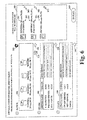
- the user operates the input device 13, selects the plural devices, referred to as "MFP5501a” and “MFP5501C” and displayed in the third display area 103, further selects the driver, referred to as “Print DRIVER” and displayed in the second display area 102, and presses down the soft key 121, the display control unit 52 causes the driver, referred to as "Print DRIVER”, to be displayed in the third display area 103, corresponding to each of the devices referred to as "MFP5501a” and “MFP5501C", as illustrated in Fig. 6 .
- the display control unit 52 causes the plural drivers to be displayed in the third display area 103, corresponding to each of the devices referred to as "MFP5501a" and "MFP5501C".
- the installation processing unit 53 installs "Print DRIVER” as the driver for the device, "MFP5501a”, and installs "Print DRIVER” as the driver for the device, "MFP5501C”.
- the display control unit 52 based on the installer program 31 (a) causes the first display area 101, the second display area 102, and the third display area 103 to be displayed within one operation screen, (b) causes the device list to be displayed in the first display area 101, (c) causes the driver list to be displayed in the second display area 102, (d) causes one device 201 or the plural devices 201 selected from the device list displayed in the first display area 101 to be displayed in the third display area 103, and (e) causes one driver 202 or the plural drivers 202 to be displayed, the one driver 202 or the plural drivers 202 being selected, with respect to one of the displayed devices 201, from the driver list displayed in the second display area 102, and associated with one of the displayed devices 201.
- the installation processing unit 53 based on the installer program 31 installs the driver 202, displayed corresponding to the device 201 displayed in the third display area 103, as a driver for the device 201.
- the display control unit 52 may determine whether or not the selected driver conforms to the displayed device. If the selected driver does not conform to the displayed device, the display control unit 52 may cause the display device 12 to display a warning.
- each of the plural drivers includes conformity data indicating a device to which the driver conforms. The display control unit 52 determines, based on the conformity data, whether or not the selected driver conforms to the displayed device.
Landscapes
- Engineering & Computer Science (AREA)
- Theoretical Computer Science (AREA)
- General Engineering & Computer Science (AREA)
- Physics & Mathematics (AREA)
- General Physics & Mathematics (AREA)
- Human Computer Interaction (AREA)
- Software Systems (AREA)
- Computer Security & Cryptography (AREA)
- Stored Programmes (AREA)
- User Interface Of Digital Computer (AREA)
Abstract
Description
- Unless otherwise indicated herein, the description in this field section or the background section is not prior art to the claims in this application and is not admitted to be prior art by inclusion in this section. The present invention relates to an installation method.
- From among devices connected to a local area network, a typical information processing device searches for one of the devices where no driver for controlling the device is installed into the information processing device. The typical information processing device displays a list of devices found out by the search. A driver of a device selected from the list by a user is installed into the information processing device.
- In the typical information processing device, it is possible for the user to select a device where a driver is to be installed into an information processing device. However, when the plurality of drivers exist for one device, it is difficult for the user to select, with visual confirmation, the device where the driver is to be installed into the information processing device, and to select the driver to be installed for the device.
- The present invention relates to an installation method and system. The installation method includes the following steps:
- generating a device list of a device or a plurality of devices that communicates with an information processing device;
- displaying a first display area, a second display area, and a third display area within one screen;
- displaying the device list in the first display area;
- displaying a driver list in the second display area;
- selecting at least one device from the displayed device list and displaying the device selected from the device list in the third display area;
- selecting at least one driver from the displayed device list and displaying the driver selected from the driver list corresponding to the device displayed in the third display area; and
- installing in the information processing device the driver displayed corresponding to the device.
- The system comprises:
- at least one device, the at least one device being an electronic device, in particular a multifunction peripheral device or a printer; and
- an information processing device to which the at least one device is connected via a network or a peripheral interface,
- a device list generation unit for generating a device list of a device that communicates with the information processing device;
- a device control unit for displaying a first display area, a second display area, and a third display area within one screen; and
- an installation processing unit,
- Additional features and advantages are described herein, and will be apparent from the following Detailed Description and the figures.
- All drawings are intended to illustrate some aspects and examples of the present invention. The drawings described are only schematic and are non-limiting, and are not necessarily drawn to scale.
- Fig. 1
- is a schematic diagram illustrating a block configuration of a system where a driver for a device is installed into an information processing device in accordance with an installer program stored in a non-transitory recording medium according to an embodiment of the present invention.
- Fig. 2
- is a schematic diagram illustrating an example of an operation screen displayed by the installer program.
- Fig. 3
- is a schematic diagram illustrating an example of a setting screen for the driver displayed when an icon in
Fig. 2 is operated. - Fig. 4
- is a schematic diagram for explaining selection of the device and a selection procedure for the driver for the selected device (1/3).
- Fig. 5
- is a schematic diagram for explaining the selection of the device and the selection procedure for the driver for the selected device (2/3).
- Fig.6
- is a schematic diagram explaining the selection of the device and the selection procedure for the driver for the selected device (3/3).
- Various embodiments are described below with reference to the figures. It should be understood, however, that numerous variations from the depicted arrangements and functions are possible while remaining in the scope and spirit of the claims. For instance, one or more elements may be added, removed, combined, distributed, substituted, re-positioned, re-ordered, and/or otherwise changed. Further, where this description refers to one or more functions being implemented on and/or by one or more devices, one or more machines, and/or one or more networks, it should be understood that one or more of such entities could carry out one or more of such functions by themselves or in cooperation, and may do so by application of any suitable combination of hardware, firmware, and/or software. For instance, one or more processors may execute one or more sets of programming instructions as at least part of carrying out one or more of the functions described herein.
-
Fig. 1 is a schematic diagram illustrating the block configuration of a system where a driver for a device is installed into an information processing device in accordance with an installer program stored in a non-transitory recording medium according to an embodiment of the present invention. - In the system illustrated in
Fig. 1 , the plurality ofdevices 2 are connected to the information processing device 1 via a network or a peripheral device interface such as a universal serial bus (USB). The information processing device 1 is a personal computer or the like, and thedevices 2 are electronic devices such as a multifunction peripheral (MFP) and a printer. - The information processing device 1 includes a
communication device 11, adisplay device 12, aninput device 13, astorage device 14, and aprocessor 15. - The
communication device 11 performs data communication with thedevices 2 via the network or the peripheral device interface. - The
display device 12 displays various kinds of screens, such as a liquid crystal display. - The
input device 13 receives a user operation, such as a keyboard, a mouse, or a touch panel. - The
storage device 14 is a non-volatile memory storing various kinds of programs and data, such as a hard disk drive or a flash memory. - In the
storage device 14, anOS program 21 of an operating system (OS) and aninstaller package 22 are stored. - For example, the
installer package 22 is downloaded from a server on the network and stored. In addition, a drive device for a recording medium in which theinstaller package 22 is recorded, such as a CD-ROM, may be connected to theprocessor 15, and theinstaller package 22 may be read out from the recording medium using the drive device. - The
installer package 22 includes aninstaller program 31, adriver program group 32, and autility program group 33. - The
driver program group 32 and theutility program group 33 are programs of drivers and utilities installable into the information processing device 1, and theinstaller program 31 is a program for installing a driver and a utility, based on thedriver program group 32 and theutility program group 33. - The
processor 15 includes a computer having a central processing unit (CPU), a read only memory (ROM), and a random access memory (RAM), a program is loaded into the RAM and executed in the CPU, and various kinds of processing units are realized. - For example, by executing the
OS program 21, anoperating system 41 is realized, and by executing theinstaller program 31, aninstaller 42 is realized. - The
installer 42 includes a devicelist generation unit 51, adisplay control unit 52, and aninstallation processing unit 53. - The device
list generation unit 51 generates a device list of thedevices 2 that communicates with the information processing device 1. - When the
installer 42 is activated, thedisplay control unit 52 causes thedisplay device 12 to display an operation screen.Fig. 2 is a schematic diagram illustrating an example of the operation screen displayed by theinstaller program 31. - The display control unit 52 (a) causes a
first display area 101, asecond display area 102, and athird display area 103 to be displayed within one operation screen, (b) causes, in thefirst display area 101, the device list thereof to be displayed, (c) causes the driver list of thedriver program group 32 to be displayed in thesecond display area 102, (d) causes onedevice 201 or a plurality ofdevices 201 selected from the device list displayed in thefirst display area 101 to be displayed in thethird display area 103, and (e) causes onedriver 202 or the plurality ofdrivers 202 to be displayed, the onedriver 202 or theplural drivers 202 being selected, with respect to one of the displayeddevices 201, from the driver list displayed in thesecond display area 102, and associated with one of the displayeddevices 201. - For example, as illustrated in
Fig. 2 , in thefirst display area 101, as each device in the device list, an icon indicating a device type, a device type name, and an IP address are displayed. In addition, the devices of the device type names, "MFP5501a", "MFP5501C", and "MFP3501", inFig. 2 are the MFPs, and the device of the device type name, "PRN1011", is the printer. In addition, "Print DRIVER" and "Print mini-DRIVER" are the drivers for print functions, and "FAX DRIVER" is the driver for a facsimile communication function. - In this embodiment, the device type name and a network identifier (here, the IP address) are displayed as one of the
devices 201, and therebelow, a driver name is displayed as one of thedevices 201. - In addition, the
display control unit 52 further causes afourth display area 104 to be displayed, causes a utility list of theutility program group 33 to be displayed in thefourth display area 104, and causes one utility or the plurality of utilities selected from the utility list to be displayed in thethird display area 103. Furthermore, thedisplay control unit 52 causes asoft key 111 to be displayed, and if thesoft key 111 is operated, thedisplay control unit 52 causes the device to be displayed in thethird display area 103, the device being selected from among the devices within the device list displayed in thefirst display area 101 when thesoft key 111 is operated. - Furthermore, the
display control unit 52 causes asoft key 112 to be displayed, and if thesoft key 112 is operated, the devicelist generation unit 51 generates the device list again, and thedisplay control unit 52 updates the device list displayed in thefirst display area 101 using the regenerated device list. - Furthermore, the
display control unit 52 causes asoft key 113 to be displayed, and if thesoft key 113 is operated, thedisplay control unit 52 causes an input screen for manually adding the device to the device list to be displayed. After that, the device input using the input screen is added to the device list displayed in thefirst display area 101. - Furthermore, the
display control unit 52 causes asoft key 121 to be displayed, and if thesoft key 121 is operated, thedisplay control unit 52 causes the driver to be displayed corresponding to one of thedevices 201, selected from among thedevices 201 displayed in thethird display area 103 when thesoft key 121 is operated, the deriver being selected from among the drivers within the driver list displayed in thesecond display area 102 when thesoft key 121 is operated. - Furthermore, the
display control unit 52 causes asoft key 141 to be displayed, and if thesoft key 141 is operated, thedisplay control unit 52 causes the utility to be displayed in thethird display area 103, the utility being selected from among utilities within the utility list displayed in thefourth display area 104 when thesoft key 141 is operated. - Furthermore, the
display control unit 52 causesicons 203 to be displayed corresponding to thedevices 201 and/or thedrivers 202 displayed in thethird display area 103. If one of theicons 203 is operated, thedisplay control unit 52 causes asetting screen 300 for inputting the setting value of thedriver 202 to be displayed. -
Fig. 3 is a schematic diagram illustrating an example of thesetting screen 300 for the driver displayed when one of theicons 203 inFig. 2 is operated. Thesetting screen 300 illustrated inFig. 3 corresponds to the driver of the device, "MFP5501a", inFig. 2 . - If one of the
icons 203 is operated when the plural drivers 202 (for example, two drivers, "Print DRIVER" and "FAX DRIVER", inFig. 2 ) are displayed with being associated with onedevice 201 displayed in thethird display area 103, thedisplay control unit 52 causes a plurality oftabs setting screen 300, as illustrated inFig. 3 . - When an
installation key 105 displayed in the operation screen is operated, theinstallation processing unit 53 installs thedriver 202 displayed corresponding to thedevice 201 in thethird display area 103, into the information processing device 1 as the driver for thedevice 201. In other words, theinstallation processing unit 53 reads out the program of thedriver 202 from thedriver program group 32 in theinstaller package 22, and incorporates the program of thedriver 202 as a portion of theOS program 21. - Furthermore, when the utility is displayed in the
third display area 103, theinstallation processing unit 53 installs, into the information processing device 1, the utility displayed in thethird display area 103, along with the driver. In other words, theinstallation processing unit 53 reads out the program of the utility from theutility program group 33 in theinstaller package 22, and incorporates the program as the portion of theOS program 21 or registers the program as an application. - Furthermore, when the setting value of the
driver 202 is input using thesetting screen 300, theinstallation processing unit 53 sets the setting value as an initial value of the setting value of the installed driver. - In addition, the selection of the device in the device list, the selection of the driver in the driver list, the selection of the utility in the utility list, the operation (for example, pressing down) of the
installation key 105, the operations (for example, pressing down) of thesoft keys icon 203 are performed by the user operating theinput device 13. - Next, installation process based on the above-described
installer program 31 will be explained. -
Fig. 4 to Fig. 6 are schematic diagrams for explaining selection of the device and a selection procedure for the driver for the selected device. - If the
installer program 31 is executed in theprocessor 15 in accordance with a specified operation of the user, thedisplay control unit 52 causes thedisplay device 12 to display such an operation screen as illustrated inFig. 2 . In addition, as illustrated in, for example,Fig. 4 , thedisplay control unit 52 causes the driver list of thedriver program group 32 to be displayed in thesecond display area 102, and causes the utility list of theutility program group 33 to be displayed in thefourth display area 104. In addition, if the devicelist generation unit 51 generates the device list of thedevices 2, thedisplay control unit 52 causes the device list to be displayed in thefirst display area 101. - In addition, as illustrated in
Fig. 4 , in an initial state, thethird display area 103 in the operation screen is blank. - In addition, if the user operates the
input device 13, selects the plural devices, referred to as "MFP5501a", "MFP5501C", and "PRN1011" and displayed in thefirst display area 101, as illustrated in, for example,Fig. 4 , and presses down thesoft key 111, thedisplay control unit 52 causes the selected devices to be displayed in thethird display area 103 as illustrated inFig. 5 . - Next, the user operates the
input device 13, selects the plural devices, referred to as "MFP5501a" and "MFP5501C" and displayed in thethird display area 103, further selects the driver, referred to as "Print DRIVER" and displayed in thesecond display area 102, and presses down thesoft key 121, thedisplay control unit 52 causes the driver, referred to as "Print DRIVER", to be displayed in thethird display area 103, corresponding to each of the devices referred to as "MFP5501a" and "MFP5501C", as illustrated inFig. 6 . - Note that, while one driver is selected from the driver list, a plurality of drivers may be selected. When the plural drivers are selected, if the
soft key 121 is pressed down, thedisplay control unit 52 causes the plural drivers to be displayed in thethird display area 103, corresponding to each of the devices referred to as "MFP5501a" and "MFP5501C". - In addition, if the user operates the
input device 13 and presses down theinstallation key 105 in a state illustrated in, for example,Fig. 6 , theinstallation processing unit 53 installs "Print DRIVER" as the driver for the device, "MFP5501a", and installs "Print DRIVER" as the driver for the device, "MFP5501C". - Accordingly, the
display control unit 52 based on the installer program 31 (a) causes thefirst display area 101, thesecond display area 102, and thethird display area 103 to be displayed within one operation screen, (b) causes the device list to be displayed in thefirst display area 101, (c) causes the driver list to be displayed in thesecond display area 102, (d) causes onedevice 201 or theplural devices 201 selected from the device list displayed in thefirst display area 101 to be displayed in thethird display area 103, and (e) causes onedriver 202 or theplural drivers 202 to be displayed, the onedriver 202 or theplural drivers 202 being selected, with respect to one of the displayeddevices 201, from the driver list displayed in thesecond display area 102, and associated with one of the displayeddevices 201. Theinstallation processing unit 53 based on theinstaller program 31 installs thedriver 202, displayed corresponding to thedevice 201 displayed in thethird display area 103, as a driver for thedevice 201. - This enables the user to simultaneously select, with visual confirmation, the device where the driver is to be installed into the information processing device 1, and the driver to be installed for the device, if a plurality of drivers (for example, "Print DRIVER" and "FAX DRIVER") exist for one device (for example, "MFP5501a").
- While various aspects and embodiments have been disclosed herein, other aspects and embodiments are possible. Other designs may be used in which the above-described components are each present.
- For example, in the above-described embodiment, when the driver is selected from the driver list corresponding to the device displayed in the
third display area 103, thedisplay control unit 52 may determine whether or not the selected driver conforms to the displayed device. If the selected driver does not conform to the displayed device, thedisplay control unit 52 may cause thedisplay device 12 to display a warning. In this case, for example, each of the plural drivers includes conformity data indicating a device to which the driver conforms. Thedisplay control unit 52 determines, based on the conformity data, whether or not the selected driver conforms to the displayed device. - It should be understood that various changes and modifications to the embodiments described herein will be apparent to those skilled in the art. Such changes and modifications may be made without departing from the spirit and scope of the present subject matter and without diminishing its intended advantages. It is therefore intended that such changes and modifications be covered by the appended claims.
wherein the installation processing unit is adapted to install in the information processing device the driver displayed corresponding to the device.
Claims (13)
- An installation method comprising the following steps:- generating a device list of a device (2, 201) or a plurality of devices (2, 201) that communicates with an information processing device (1);- displaying a first display area (101), a second display area (102), and a third display area (103) within one screen;- displaying the device list in the first display area (101);- displaying a driver list in the second display area (102);- selecting at least one device (2, 201) from the displayed device list and displaying the device (2, 201) selected from the device list in the third display area (103);- selecting at least one driver (202) from the displayed device list and displaying the driver (202) selected from the driver list corresponding to the device (201) displayed in the third display area (103); and- installing in the information processing device (1) the driver (202) displayed corresponding to the device (2).
- The installation method according to claim 1, further comprising the following step:- determining whether or not the selected driver (202) conforms to the displayed device (2, 201), when the driver (202) is selected from the driver list.
- The installation method according to Claim 2, further comprising the following step:- displaying a warning, if the selected driver (202) does not conform to the displayed device (2, 201).
- The installation method according to one of the claims 1 to 3, further comprising the following steps:- displaying an icon (203) corresponding to the device (201) and/or the driver (202) displayed in the third display area (103); and- displaying a setting screen (300) for inputting a setting value of the driver, if the icon (203) is operated.
- The installation method according to Claim 4, further comprising:- displaying a plurality of tabs (301; 302) for inputting the setting values of the plural drivers in the setting screen (300).
- The installation method according to one of the claims 1 to 5, further comprising the following steps:- displaying a soft key (121); and- displaying, when the soft key (121) is operated, the driver corresponding to the device (201) that is selected in the third display area (103) when the soft key (121) is operated, the driver being selected within the driver list displayed in the second display area (102) when the soft key (121) is operated.
- The installation method according to one of the claims 1 to 6, further comprising the following steps:- displaying a fourth display area (104) to be displayed within the one screen;- displaying a utility list in the fourth display area (104);- selecting a utility from the displayed utility list and displaying the utility selected from the utility list in the third display area (103); and- installing in the information processing device (1) the utility displayed in the third display area together with the driver (202).
- The installation method according to one of the claims 1 to 7,
wherein the driver (202) selected from the driver list is displayed in the third display area (103) together with selected device (2, 201). - A system comprising:- at least one device (2, 201), the at least one device (2, 201) being an electronic device, in particular a multifunction peripheral device or a printer; and- an information processing device (1) to which the at least one device (2, 201) is connected via a network or a peripheral interface,wherein the information processing device (1) comprises:- a device list generation unit (51) for generating a device list of a device (2) that communicates with the information processing device (1);- a device control unit (52) for displaying a first display area (101), a second display area (102), and a third display area (103) within one screen; and- an installation processing unit (53),wherein the display control unit (52) is adapted to display the device list in the first display area (101), to display a driver in the second display area (102), to display a device (2) selected from the device list in the third display area (103), and to display the driver selected from the driver list corresponding to the device (201) displayed in the third display area (103); and
wherein the installation processing unit (53) is adapted to install in the information processing device (1) the driver (202) displayed corresponding to the device (2). - The system according to claim 9,
wherein the display control unit (52) is further adapted to determine whether or not the selected driver conforms to the displayed device, when the driver is selected from the driver list. - The sytstem according to claim 9 or 10,
wherein the display control unit (52)is further adapted to display an icon (203) corresponding to the device (201) and/or the driver (202) displayed in the third display area (103); and to display a setting screen (300) for inputting a setting value of the driver, if the icon (203) is operated. - The system according to one of the claims 9 to 11,
wherein the display control unit (52) is further adapted to display a soft key (121); and to display, when the soft key (121) is operated, the driver corresponding to the device (201) that is selected in the third display area (103) when the soft key (121) is operated, the driver being selected within the driver list displayed in the second display area (102) when the soft key (121) is operated. - The system according to one of the claims 9 to 12,
wherein the display control unit (52) is further adapted to display a fourth display area (104) to be displayed within the one screen; to display a utility list in the fourth display area (104); to display a utility selected from the utility list in the third display area (103); and to install in the information processing device (1), the utility displayed in the third display area, along with the driver (202).
Applications Claiming Priority (1)
| Application Number | Priority Date | Filing Date | Title |
|---|---|---|---|
| JP2013107509A JP5932712B2 (en) | 2013-05-21 | 2013-05-21 | Installer program and installation method |
Publications (2)
| Publication Number | Publication Date |
|---|---|
| EP2806349A1 true EP2806349A1 (en) | 2014-11-26 |
| EP2806349B1 EP2806349B1 (en) | 2019-05-08 |
Family
ID=50980910
Family Applications (1)
| Application Number | Title | Priority Date | Filing Date |
|---|---|---|---|
| EP14169201.2A Not-in-force EP2806349B1 (en) | 2013-05-21 | 2014-05-21 | Installation method |
Country Status (4)
| Country | Link |
|---|---|
| US (1) | US9092169B2 (en) |
| EP (1) | EP2806349B1 (en) |
| JP (1) | JP5932712B2 (en) |
| CN (1) | CN104182246B (en) |
Families Citing this family (2)
| Publication number | Priority date | Publication date | Assignee | Title |
|---|---|---|---|---|
| JPH0723757B2 (en) | 1988-03-17 | 1995-03-15 | 積水化学工業株式会社 | Composite pipe |
| JPH0726707B2 (en) | 1989-02-13 | 1995-03-29 | 積水化学工業株式会社 | Composite pipe |
Citations (2)
| Publication number | Priority date | Publication date | Assignee | Title |
|---|---|---|---|---|
| US20080126963A1 (en) * | 2006-06-30 | 2008-05-29 | Samsung Electronics Co., Ltd. | User terminal to manage driver and network port and method of controlling the same |
| US20080201714A1 (en) * | 2007-02-16 | 2008-08-21 | Canon Kabushiki Kaisha | Information processing apparatus for controlling installation, method for controlling the apparatus and control program for executing the method |
Family Cites Families (14)
| Publication number | Priority date | Publication date | Assignee | Title |
|---|---|---|---|---|
| JP4371673B2 (en) * | 2003-02-28 | 2009-11-25 | キヤノン株式会社 | Program installation method and server device |
| JP4599206B2 (en) * | 2005-03-29 | 2010-12-15 | キヤノン株式会社 | Information processing apparatus, information processing apparatus control method, program, and storage medium |
| JP4579115B2 (en) * | 2005-09-21 | 2010-11-10 | 株式会社リコー | Print control apparatus, print control method, and print control program |
| JP2008234118A (en) * | 2007-03-19 | 2008-10-02 | Seiko Epson Corp | User interface providing apparatus, user interface generation method, and program. |
| JP4725559B2 (en) | 2007-08-03 | 2011-07-13 | ブラザー工業株式会社 | Information processing apparatus and installation program |
| JP2009217321A (en) * | 2008-03-07 | 2009-09-24 | Fuji Xerox Co Ltd | Information processor and information processing program |
| JP5489619B2 (en) * | 2009-09-29 | 2014-05-14 | キヤノン株式会社 | Information processing apparatus and method |
| KR101926592B1 (en) * | 2009-12-16 | 2019-03-08 | 에이치피프린팅코리아 유한회사 | User terminal device for managing network device and method thereof |
| JP2012027573A (en) * | 2010-07-21 | 2012-02-09 | Canon Inc | Information processor, information processing method and program |
| DE102010033740A1 (en) * | 2010-08-07 | 2012-02-09 | Manroland Ag | Printing press control station |
| JP5545542B2 (en) * | 2010-08-27 | 2014-07-09 | ブラザー工業株式会社 | Software management apparatus and software management system |
| JP5725946B2 (en) * | 2011-04-11 | 2015-05-27 | キヤノン株式会社 | Server apparatus, server apparatus control method, and program |
| JP2013073321A (en) * | 2011-09-27 | 2013-04-22 | Oki Data Corp | Installer program or installation method |
| JP2013254483A (en) * | 2012-05-11 | 2013-12-19 | Ricoh Co Ltd | Information processing apparatus, control program of information processing apparatus, and image forming apparatus |
-
2013
- 2013-05-21 JP JP2013107509A patent/JP5932712B2/en not_active Expired - Fee Related
-
2014
- 2014-05-21 CN CN201410216423.7A patent/CN104182246B/en not_active Expired - Fee Related
- 2014-05-21 EP EP14169201.2A patent/EP2806349B1/en not_active Not-in-force
- 2014-05-21 US US14/283,283 patent/US9092169B2/en not_active Expired - Fee Related
Patent Citations (2)
| Publication number | Priority date | Publication date | Assignee | Title |
|---|---|---|---|---|
| US20080126963A1 (en) * | 2006-06-30 | 2008-05-29 | Samsung Electronics Co., Ltd. | User terminal to manage driver and network port and method of controlling the same |
| US20080201714A1 (en) * | 2007-02-16 | 2008-08-21 | Canon Kabushiki Kaisha | Information processing apparatus for controlling installation, method for controlling the apparatus and control program for executing the method |
Also Published As
| Publication number | Publication date |
|---|---|
| CN104182246A (en) | 2014-12-03 |
| US20140347686A1 (en) | 2014-11-27 |
| CN104182246B (en) | 2017-07-07 |
| JP2014229032A (en) | 2014-12-08 |
| JP5932712B2 (en) | 2016-06-08 |
| EP2806349B1 (en) | 2019-05-08 |
| US9092169B2 (en) | 2015-07-28 |
Similar Documents
| Publication | Publication Date | Title |
|---|---|---|
| US10180831B2 (en) | Terminal device for downloading and installing an application and method thereof | |
| US9075627B2 (en) | Server connected to image forming apparatus and client, client, and method of remotely installing driver of image forming apparatus | |
| JP4725559B2 (en) | Information processing apparatus and installation program | |
| US20100328689A1 (en) | Host device and image forming apparatus controlled by host device, and peripheral device control method | |
| US20140298310A1 (en) | Information processing apparatus, firmware renewing method, and computer program | |
| US9170763B2 (en) | Information processing apparatus and control method | |
| US8861021B2 (en) | Installation method, installation program and computer-readable record medium | |
| US20130301069A1 (en) | Information processing device, computer program product, and image forming apparatus | |
| JP2016194785A (en) | Print control program, print control method, and information processor | |
| US20170163835A1 (en) | Information processing apparatus that installs module, method of controlling the same, and storage medium | |
| JP2010079348A (en) | Program installation device and computer program | |
| JP4981936B2 (en) | Installation method of installer and printer driver | |
| JP4983815B2 (en) | Information processing apparatus and control program | |
| WO2014136429A1 (en) | Information processing apparatus and method for the same | |
| EP2806349B1 (en) | Installation method | |
| JP2009093262A (en) | Installation program | |
| JP6089558B2 (en) | Driver management program, uninstall program, and information processing apparatus | |
| US9244670B2 (en) | Driver managing program and information processing | |
| JP5900146B2 (en) | Control device, printer driver program, and setting method | |
| JP6455478B2 (en) | Information processing apparatus, program, and software module | |
| JP6060686B2 (en) | Control device, printer driver program, and setting method | |
| US9277079B2 (en) | Image forming apparatus and method for displaying application screen of image forming apparatus that ensures display of application screen on operation panel with different resolution | |
| CN106293451A (en) | Image processing system and software keyboard display packing | |
| EP2282507A2 (en) | Host device with universal image scanning device driver and driver management method thereof | |
| JP2008234118A (en) | User interface providing apparatus, user interface generation method, and program. |
Legal Events
| Date | Code | Title | Description |
|---|---|---|---|
| PUAI | Public reference made under article 153(3) epc to a published international application that has entered the european phase |
Free format text: ORIGINAL CODE: 0009012 |
|
| 17P | Request for examination filed |
Effective date: 20140521 |
|
| AK | Designated contracting states |
Kind code of ref document: A1 Designated state(s): AL AT BE BG CH CY CZ DE DK EE ES FI FR GB GR HR HU IE IS IT LI LT LU LV MC MK MT NL NO PL PT RO RS SE SI SK SM TR |
|
| AX | Request for extension of the european patent |
Extension state: BA ME |
|
| R17P | Request for examination filed (corrected) |
Effective date: 20150305 |
|
| RBV | Designated contracting states (corrected) |
Designated state(s): AL AT BE BG CH CY CZ DE DK EE ES FI FR GB GR HR HU IE IS IT LI LT LU LV MC MK MT NL NO PL PT RO RS SE SI SK SM TR |
|
| STAA | Information on the status of an ep patent application or granted ep patent |
Free format text: STATUS: EXAMINATION IS IN PROGRESS |
|
| 17Q | First examination report despatched |
Effective date: 20180619 |
|
| GRAP | Despatch of communication of intention to grant a patent |
Free format text: ORIGINAL CODE: EPIDOSNIGR1 |
|
| STAA | Information on the status of an ep patent application or granted ep patent |
Free format text: STATUS: GRANT OF PATENT IS INTENDED |
|
| INTG | Intention to grant announced |
Effective date: 20181119 |
|
| GRAS | Grant fee paid |
Free format text: ORIGINAL CODE: EPIDOSNIGR3 |
|
| GRAA | (expected) grant |
Free format text: ORIGINAL CODE: 0009210 |
|
| STAA | Information on the status of an ep patent application or granted ep patent |
Free format text: STATUS: THE PATENT HAS BEEN GRANTED |
|
| AK | Designated contracting states |
Kind code of ref document: B1 Designated state(s): AL AT BE BG CH CY CZ DE DK EE ES FI FR GB GR HR HU IE IS IT LI LT LU LV MC MK MT NL NO PL PT RO RS SE SI SK SM TR |
|
| REG | Reference to a national code |
Ref country code: GB Ref legal event code: FG4D |
|
| REG | Reference to a national code |
Ref country code: CH Ref legal event code: EP Ref country code: AT Ref legal event code: REF Ref document number: 1131244 Country of ref document: AT Kind code of ref document: T Effective date: 20190515 |
|
| REG | Reference to a national code |
Ref country code: DE Ref legal event code: R096 Ref document number: 602014046141 Country of ref document: DE |
|
| REG | Reference to a national code |
Ref country code: IE Ref legal event code: FG4D |
|
| REG | Reference to a national code |
Ref country code: NL Ref legal event code: MP Effective date: 20190508 |
|
| REG | Reference to a national code |
Ref country code: LT Ref legal event code: MG4D |
|
| PG25 | Lapsed in a contracting state [announced via postgrant information from national office to epo] |
Ref country code: LT Free format text: LAPSE BECAUSE OF FAILURE TO SUBMIT A TRANSLATION OF THE DESCRIPTION OR TO PAY THE FEE WITHIN THE PRESCRIBED TIME-LIMIT Effective date: 20190508 Ref country code: ES Free format text: LAPSE BECAUSE OF FAILURE TO SUBMIT A TRANSLATION OF THE DESCRIPTION OR TO PAY THE FEE WITHIN THE PRESCRIBED TIME-LIMIT Effective date: 20190508 Ref country code: NL Free format text: LAPSE BECAUSE OF FAILURE TO SUBMIT A TRANSLATION OF THE DESCRIPTION OR TO PAY THE FEE WITHIN THE PRESCRIBED TIME-LIMIT Effective date: 20190508 Ref country code: SE Free format text: LAPSE BECAUSE OF FAILURE TO SUBMIT A TRANSLATION OF THE DESCRIPTION OR TO PAY THE FEE WITHIN THE PRESCRIBED TIME-LIMIT Effective date: 20190508 Ref country code: HR Free format text: LAPSE BECAUSE OF FAILURE TO SUBMIT A TRANSLATION OF THE DESCRIPTION OR TO PAY THE FEE WITHIN THE PRESCRIBED TIME-LIMIT Effective date: 20190508 Ref country code: NO Free format text: LAPSE BECAUSE OF FAILURE TO SUBMIT A TRANSLATION OF THE DESCRIPTION OR TO PAY THE FEE WITHIN THE PRESCRIBED TIME-LIMIT Effective date: 20190808 Ref country code: FI Free format text: LAPSE BECAUSE OF FAILURE TO SUBMIT A TRANSLATION OF THE DESCRIPTION OR TO PAY THE FEE WITHIN THE PRESCRIBED TIME-LIMIT Effective date: 20190508 Ref country code: PT Free format text: LAPSE BECAUSE OF FAILURE TO SUBMIT A TRANSLATION OF THE DESCRIPTION OR TO PAY THE FEE WITHIN THE PRESCRIBED TIME-LIMIT Effective date: 20190908 Ref country code: AL Free format text: LAPSE BECAUSE OF FAILURE TO SUBMIT A TRANSLATION OF THE DESCRIPTION OR TO PAY THE FEE WITHIN THE PRESCRIBED TIME-LIMIT Effective date: 20190508 |
|
| PG25 | Lapsed in a contracting state [announced via postgrant information from national office to epo] |
Ref country code: LV Free format text: LAPSE BECAUSE OF FAILURE TO SUBMIT A TRANSLATION OF THE DESCRIPTION OR TO PAY THE FEE WITHIN THE PRESCRIBED TIME-LIMIT Effective date: 20190508 Ref country code: GR Free format text: LAPSE BECAUSE OF FAILURE TO SUBMIT A TRANSLATION OF THE DESCRIPTION OR TO PAY THE FEE WITHIN THE PRESCRIBED TIME-LIMIT Effective date: 20190809 Ref country code: BG Free format text: LAPSE BECAUSE OF FAILURE TO SUBMIT A TRANSLATION OF THE DESCRIPTION OR TO PAY THE FEE WITHIN THE PRESCRIBED TIME-LIMIT Effective date: 20190808 Ref country code: RS Free format text: LAPSE BECAUSE OF FAILURE TO SUBMIT A TRANSLATION OF THE DESCRIPTION OR TO PAY THE FEE WITHIN THE PRESCRIBED TIME-LIMIT Effective date: 20190508 |
|
| REG | Reference to a national code |
Ref country code: AT Ref legal event code: MK05 Ref document number: 1131244 Country of ref document: AT Kind code of ref document: T Effective date: 20190508 |
|
| REG | Reference to a national code |
Ref country code: CH Ref legal event code: PL |
|
| PG25 | Lapsed in a contracting state [announced via postgrant information from national office to epo] |
Ref country code: CZ Free format text: LAPSE BECAUSE OF FAILURE TO SUBMIT A TRANSLATION OF THE DESCRIPTION OR TO PAY THE FEE WITHIN THE PRESCRIBED TIME-LIMIT Effective date: 20190508 Ref country code: CH Free format text: LAPSE BECAUSE OF NON-PAYMENT OF DUE FEES Effective date: 20190531 Ref country code: RO Free format text: LAPSE BECAUSE OF FAILURE TO SUBMIT A TRANSLATION OF THE DESCRIPTION OR TO PAY THE FEE WITHIN THE PRESCRIBED TIME-LIMIT Effective date: 20190508 Ref country code: SK Free format text: LAPSE BECAUSE OF FAILURE TO SUBMIT A TRANSLATION OF THE DESCRIPTION OR TO PAY THE FEE WITHIN THE PRESCRIBED TIME-LIMIT Effective date: 20190508 Ref country code: EE Free format text: LAPSE BECAUSE OF FAILURE TO SUBMIT A TRANSLATION OF THE DESCRIPTION OR TO PAY THE FEE WITHIN THE PRESCRIBED TIME-LIMIT Effective date: 20190508 Ref country code: AT Free format text: LAPSE BECAUSE OF FAILURE TO SUBMIT A TRANSLATION OF THE DESCRIPTION OR TO PAY THE FEE WITHIN THE PRESCRIBED TIME-LIMIT Effective date: 20190508 Ref country code: LI Free format text: LAPSE BECAUSE OF NON-PAYMENT OF DUE FEES Effective date: 20190531 Ref country code: DK Free format text: LAPSE BECAUSE OF FAILURE TO SUBMIT A TRANSLATION OF THE DESCRIPTION OR TO PAY THE FEE WITHIN THE PRESCRIBED TIME-LIMIT Effective date: 20190508 |
|
| REG | Reference to a national code |
Ref country code: BE Ref legal event code: MM Effective date: 20190531 |
|
| REG | Reference to a national code |
Ref country code: DE Ref legal event code: R097 Ref document number: 602014046141 Country of ref document: DE |
|
| PG25 | Lapsed in a contracting state [announced via postgrant information from national office to epo] |
Ref country code: IT Free format text: LAPSE BECAUSE OF FAILURE TO SUBMIT A TRANSLATION OF THE DESCRIPTION OR TO PAY THE FEE WITHIN THE PRESCRIBED TIME-LIMIT Effective date: 20190508 Ref country code: LU Free format text: LAPSE BECAUSE OF NON-PAYMENT OF DUE FEES Effective date: 20190521 Ref country code: SM Free format text: LAPSE BECAUSE OF FAILURE TO SUBMIT A TRANSLATION OF THE DESCRIPTION OR TO PAY THE FEE WITHIN THE PRESCRIBED TIME-LIMIT Effective date: 20190508 Ref country code: MC Free format text: LAPSE BECAUSE OF FAILURE TO SUBMIT A TRANSLATION OF THE DESCRIPTION OR TO PAY THE FEE WITHIN THE PRESCRIBED TIME-LIMIT Effective date: 20190508 |
|
| PLBE | No opposition filed within time limit |
Free format text: ORIGINAL CODE: 0009261 |
|
| STAA | Information on the status of an ep patent application or granted ep patent |
Free format text: STATUS: NO OPPOSITION FILED WITHIN TIME LIMIT |
|
| PG25 | Lapsed in a contracting state [announced via postgrant information from national office to epo] |
Ref country code: TR Free format text: LAPSE BECAUSE OF FAILURE TO SUBMIT A TRANSLATION OF THE DESCRIPTION OR TO PAY THE FEE WITHIN THE PRESCRIBED TIME-LIMIT Effective date: 20190508 |
|
| 26N | No opposition filed |
Effective date: 20200211 |
|
| PG25 | Lapsed in a contracting state [announced via postgrant information from national office to epo] |
Ref country code: IE Free format text: LAPSE BECAUSE OF NON-PAYMENT OF DUE FEES Effective date: 20190521 Ref country code: PL Free format text: LAPSE BECAUSE OF FAILURE TO SUBMIT A TRANSLATION OF THE DESCRIPTION OR TO PAY THE FEE WITHIN THE PRESCRIBED TIME-LIMIT Effective date: 20190508 |
|
| PG25 | Lapsed in a contracting state [announced via postgrant information from national office to epo] |
Ref country code: SI Free format text: LAPSE BECAUSE OF FAILURE TO SUBMIT A TRANSLATION OF THE DESCRIPTION OR TO PAY THE FEE WITHIN THE PRESCRIBED TIME-LIMIT Effective date: 20190508 Ref country code: BE Free format text: LAPSE BECAUSE OF NON-PAYMENT OF DUE FEES Effective date: 20190531 |
|
| PGFP | Annual fee paid to national office [announced via postgrant information from national office to epo] |
Ref country code: DE Payment date: 20200506 Year of fee payment: 7 Ref country code: FR Payment date: 20200414 Year of fee payment: 7 |
|
| PGFP | Annual fee paid to national office [announced via postgrant information from national office to epo] |
Ref country code: GB Payment date: 20200513 Year of fee payment: 7 |
|
| PG25 | Lapsed in a contracting state [announced via postgrant information from national office to epo] |
Ref country code: CY Free format text: LAPSE BECAUSE OF FAILURE TO SUBMIT A TRANSLATION OF THE DESCRIPTION OR TO PAY THE FEE WITHIN THE PRESCRIBED TIME-LIMIT Effective date: 20190508 |
|
| PG25 | Lapsed in a contracting state [announced via postgrant information from national office to epo] |
Ref country code: IS Free format text: LAPSE BECAUSE OF FAILURE TO SUBMIT A TRANSLATION OF THE DESCRIPTION OR TO PAY THE FEE WITHIN THE PRESCRIBED TIME-LIMIT Effective date: 20190908 |
|
| PG25 | Lapsed in a contracting state [announced via postgrant information from national office to epo] |
Ref country code: HU Free format text: LAPSE BECAUSE OF FAILURE TO SUBMIT A TRANSLATION OF THE DESCRIPTION OR TO PAY THE FEE WITHIN THE PRESCRIBED TIME-LIMIT; INVALID AB INITIO Effective date: 20140521 Ref country code: MT Free format text: LAPSE BECAUSE OF FAILURE TO SUBMIT A TRANSLATION OF THE DESCRIPTION OR TO PAY THE FEE WITHIN THE PRESCRIBED TIME-LIMIT Effective date: 20190508 |
|
| REG | Reference to a national code |
Ref country code: DE Ref legal event code: R119 Ref document number: 602014046141 Country of ref document: DE |
|
| GBPC | Gb: european patent ceased through non-payment of renewal fee |
Effective date: 20210521 |
|
| PG25 | Lapsed in a contracting state [announced via postgrant information from national office to epo] |
Ref country code: GB Free format text: LAPSE BECAUSE OF NON-PAYMENT OF DUE FEES Effective date: 20210521 Ref country code: DE Free format text: LAPSE BECAUSE OF NON-PAYMENT OF DUE FEES Effective date: 20211201 |
|
| PG25 | Lapsed in a contracting state [announced via postgrant information from national office to epo] |
Ref country code: FR Free format text: LAPSE BECAUSE OF NON-PAYMENT OF DUE FEES Effective date: 20210531 |
|
| PG25 | Lapsed in a contracting state [announced via postgrant information from national office to epo] |
Ref country code: MK Free format text: LAPSE BECAUSE OF FAILURE TO SUBMIT A TRANSLATION OF THE DESCRIPTION OR TO PAY THE FEE WITHIN THE PRESCRIBED TIME-LIMIT Effective date: 20190508 |