EP2806331B1 - Appareil électronique et méthode de déverrouillage correspondante - Google Patents
Appareil électronique et méthode de déverrouillage correspondante Download PDFInfo
- Publication number
- EP2806331B1 EP2806331B1 EP14162777.8A EP14162777A EP2806331B1 EP 2806331 B1 EP2806331 B1 EP 2806331B1 EP 14162777 A EP14162777 A EP 14162777A EP 2806331 B1 EP2806331 B1 EP 2806331B1
- Authority
- EP
- European Patent Office
- Prior art keywords
- touch screen
- electronic device
- flexible touch
- bending
- user
- Prior art date
- Legal status (The legal status is an assumption and is not a legal conclusion. Google has not performed a legal analysis and makes no representation as to the accuracy of the status listed.)
- Active
Links
Images








Classifications
-
- G—PHYSICS
- G06—COMPUTING OR CALCULATING; COUNTING
- G06F—ELECTRIC DIGITAL DATA PROCESSING
- G06F3/00—Input arrangements for transferring data to be processed into a form capable of being handled by the computer; Output arrangements for transferring data from processing unit to output unit, e.g. interface arrangements
- G06F3/01—Input arrangements or combined input and output arrangements for interaction between user and computer
- G06F3/03—Arrangements for converting the position or the displacement of a member into a coded form
- G06F3/041—Digitisers, e.g. for touch screens or touch pads, characterised by the transducing means
- G06F3/0416—Control or interface arrangements specially adapted for digitisers
-
- G—PHYSICS
- G06—COMPUTING OR CALCULATING; COUNTING
- G06F—ELECTRIC DIGITAL DATA PROCESSING
- G06F3/00—Input arrangements for transferring data to be processed into a form capable of being handled by the computer; Output arrangements for transferring data from processing unit to output unit, e.g. interface arrangements
- G06F3/01—Input arrangements or combined input and output arrangements for interaction between user and computer
-
- G—PHYSICS
- G06—COMPUTING OR CALCULATING; COUNTING
- G06F—ELECTRIC DIGITAL DATA PROCESSING
- G06F1/00—Details not covered by groups G06F3/00 - G06F13/00 and G06F21/00
- G06F1/16—Constructional details or arrangements
- G06F1/1613—Constructional details or arrangements for portable computers
- G06F1/1633—Constructional details or arrangements of portable computers not specific to the type of enclosures covered by groups G06F1/1615 - G06F1/1626
- G06F1/1637—Details related to the display arrangement, including those related to the mounting of the display in the housing
- G06F1/1643—Details related to the display arrangement, including those related to the mounting of the display in the housing the display being associated to a digitizer, e.g. laptops that can be used as penpads
-
- G—PHYSICS
- G06—COMPUTING OR CALCULATING; COUNTING
- G06F—ELECTRIC DIGITAL DATA PROCESSING
- G06F1/00—Details not covered by groups G06F3/00 - G06F13/00 and G06F21/00
- G06F1/16—Constructional details or arrangements
- G06F1/1613—Constructional details or arrangements for portable computers
- G06F1/1633—Constructional details or arrangements of portable computers not specific to the type of enclosures covered by groups G06F1/1615 - G06F1/1626
- G06F1/1637—Details related to the display arrangement, including those related to the mounting of the display in the housing
- G06F1/1652—Details related to the display arrangement, including those related to the mounting of the display in the housing the display being flexible, e.g. mimicking a sheet of paper, or rollable
-
- G—PHYSICS
- G06—COMPUTING OR CALCULATING; COUNTING
- G06F—ELECTRIC DIGITAL DATA PROCESSING
- G06F3/00—Input arrangements for transferring data to be processed into a form capable of being handled by the computer; Output arrangements for transferring data from processing unit to output unit, e.g. interface arrangements
- G06F3/01—Input arrangements or combined input and output arrangements for interaction between user and computer
- G06F3/017—Gesture based interaction, e.g. based on a set of recognized hand gestures
-
- G—PHYSICS
- G06—COMPUTING OR CALCULATING; COUNTING
- G06F—ELECTRIC DIGITAL DATA PROCESSING
- G06F3/00—Input arrangements for transferring data to be processed into a form capable of being handled by the computer; Output arrangements for transferring data from processing unit to output unit, e.g. interface arrangements
- G06F3/01—Input arrangements or combined input and output arrangements for interaction between user and computer
- G06F3/03—Arrangements for converting the position or the displacement of a member into a coded form
- G06F3/041—Digitisers, e.g. for touch screens or touch pads, characterised by the transducing means
-
- G—PHYSICS
- G06—COMPUTING OR CALCULATING; COUNTING
- G06F—ELECTRIC DIGITAL DATA PROCESSING
- G06F3/00—Input arrangements for transferring data to be processed into a form capable of being handled by the computer; Output arrangements for transferring data from processing unit to output unit, e.g. interface arrangements
- G06F3/01—Input arrangements or combined input and output arrangements for interaction between user and computer
- G06F3/03—Arrangements for converting the position or the displacement of a member into a coded form
- G06F3/041—Digitisers, e.g. for touch screens or touch pads, characterised by the transducing means
- G06F3/0412—Digitisers structurally integrated in a display
-
- G—PHYSICS
- G06—COMPUTING OR CALCULATING; COUNTING
- G06F—ELECTRIC DIGITAL DATA PROCESSING
- G06F3/00—Input arrangements for transferring data to be processed into a form capable of being handled by the computer; Output arrangements for transferring data from processing unit to output unit, e.g. interface arrangements
- G06F3/01—Input arrangements or combined input and output arrangements for interaction between user and computer
- G06F3/048—Interaction techniques based on graphical user interfaces [GUI]
-
- G—PHYSICS
- G06—COMPUTING OR CALCULATING; COUNTING
- G06F—ELECTRIC DIGITAL DATA PROCESSING
- G06F3/00—Input arrangements for transferring data to be processed into a form capable of being handled by the computer; Output arrangements for transferring data from processing unit to output unit, e.g. interface arrangements
- G06F3/01—Input arrangements or combined input and output arrangements for interaction between user and computer
- G06F3/048—Interaction techniques based on graphical user interfaces [GUI]
- G06F3/0487—Interaction techniques based on graphical user interfaces [GUI] using specific features provided by the input device, e.g. functions controlled by the rotation of a mouse with dual sensing arrangements, or of the nature of the input device, e.g. tap gestures based on pressure sensed by a digitiser
-
- G—PHYSICS
- G06—COMPUTING OR CALCULATING; COUNTING
- G06F—ELECTRIC DIGITAL DATA PROCESSING
- G06F3/00—Input arrangements for transferring data to be processed into a form capable of being handled by the computer; Output arrangements for transferring data from processing unit to output unit, e.g. interface arrangements
- G06F3/14—Digital output to display device ; Cooperation and interconnection of the display device with other functional units
-
- H—ELECTRICITY
- H04—ELECTRIC COMMUNICATION TECHNIQUE
- H04M—TELEPHONIC COMMUNICATION
- H04M1/00—Substation equipment, e.g. for use by subscribers
- H04M1/02—Constructional features of telephone sets
- H04M1/0202—Portable telephone sets, e.g. cordless phones, mobile phones or bar type handsets
- H04M1/026—Details of the structure or mounting of specific components
- H04M1/0266—Details of the structure or mounting of specific components for a display module assembly
- H04M1/0268—Details of the structure or mounting of specific components for a display module assembly including a flexible display panel
-
- G—PHYSICS
- G02—OPTICS
- G02F—OPTICAL DEVICES OR ARRANGEMENTS FOR THE CONTROL OF LIGHT BY MODIFICATION OF THE OPTICAL PROPERTIES OF THE MEDIA OF THE ELEMENTS INVOLVED THEREIN; NON-LINEAR OPTICS; FREQUENCY-CHANGING OF LIGHT; OPTICAL LOGIC ELEMENTS; OPTICAL ANALOGUE/DIGITAL CONVERTERS
- G02F1/00—Devices or arrangements for the control of the intensity, colour, phase, polarisation or direction of light arriving from an independent light source, e.g. switching, gating or modulating; Non-linear optics
- G02F1/01—Devices or arrangements for the control of the intensity, colour, phase, polarisation or direction of light arriving from an independent light source, e.g. switching, gating or modulating; Non-linear optics for the control of the intensity, phase, polarisation or colour
- G02F1/13—Devices or arrangements for the control of the intensity, colour, phase, polarisation or direction of light arriving from an independent light source, e.g. switching, gating or modulating; Non-linear optics for the control of the intensity, phase, polarisation or colour based on liquid crystals, e.g. single liquid crystal display cells
- G02F1/133—Constructional arrangements; Operation of liquid crystal cells; Circuit arrangements
- G02F1/1333—Constructional arrangements; Manufacturing methods
- G02F1/133305—Flexible substrates, e.g. plastics, organic film
-
- G—PHYSICS
- G06—COMPUTING OR CALCULATING; COUNTING
- G06F—ELECTRIC DIGITAL DATA PROCESSING
- G06F2203/00—Indexing scheme relating to G06F3/00 - G06F3/048
- G06F2203/041—Indexing scheme relating to G06F3/041 - G06F3/045
- G06F2203/04102—Flexible digitiser, i.e. constructional details for allowing the whole digitising part of a device to be flexed or rolled like a sheet of paper
-
- H—ELECTRICITY
- H04—ELECTRIC COMMUNICATION TECHNIQUE
- H04M—TELEPHONIC COMMUNICATION
- H04M1/00—Substation equipment, e.g. for use by subscribers
- H04M1/02—Constructional features of telephone sets
- H04M1/0202—Portable telephone sets, e.g. cordless phones, mobile phones or bar type handsets
- H04M1/026—Details of the structure or mounting of specific components
- H04M1/0266—Details of the structure or mounting of specific components for a display module assembly
- H04M1/0268—Details of the structure or mounting of specific components for a display module assembly including a flexible display panel
- H04M1/0269—Details of the structure or mounting of specific components for a display module assembly including a flexible display panel mounted in a fixed curved configuration, e.g. display curved around the edges of the telephone housing
-
- H—ELECTRICITY
- H04—ELECTRIC COMMUNICATION TECHNIQUE
- H04M—TELEPHONIC COMMUNICATION
- H04M2250/00—Details of telephonic subscriber devices
- H04M2250/22—Details of telephonic subscriber devices including a touch pad, a touch sensor or a touch detector
Definitions
- the disclosure relates to electronic devices, unlocking methods thereof and zooming and toggling control methods thereof. More particularly, aspects of the present disclosure are directed to an electronic device capable of performing an unlocking, zooming and toggling operation using a bending action.
- Such an electronic device generally includes a touch screen that displays graphics and text while sensing touches.
- a touch screen displays a guide image for transition from a lock state to an unlock state and, after touching a handler included in the guide image, a user performs a moving operation in the guided direction to unlock the electronic device.
- Flexible touch screens which are bendable due to use of a flexible substrate, are under development. Since flexible touch screens are advantageous in easy deformation, various studies have been conducted to employ the flexible touch screens for next-generation electronic.
- EP2458829 A2 discloses a mobile terminal including a body having at least one partial region including a flexible material; a flexible display to display information; a sensor unit to detect a first physical bending of the flexible display; and a controller that can unlock the flexible display if at least one reference line passing through a corresponding curved portion attributed to at least one bending of the flexible display matches a predetermined reference line.
- US2011298691 A1 discloses an information handling system in which a captcha request is transmitted to a foldable display screen. One or more bends of the foldable display screen received in response to the captcha are compared to one or more expected bends included in the captcha.
- a requested action is performed in response to the comparison revealing that the received one or more bends match the one or more expected bends.
- Requested actions can include a variety of different actions including unlocking a system, viewing a website or webpage provided by a remote system, accessing a program or function local to the user's system to which the foldable display screen is attached, or any other function either local or remote.
- US2013010405 A1 discloses an electronic device with a flexible display that has a housing that is based on a rigid housing structure and an associated flexible support structure such as a sheet of flexible metal, a flexible polymer or a flexible composite structure.
- the invention relates to an electronic device as defined in the appended independent claim 1.
- Preferred embodiments are defined in the dependent claims.
- the embodiments and/or examples of the following description which are not covered by the appended claims are considered as not being part of the present invention.
- a zooming and toggling control method of an electronic device may include displaying a target image on an electronic device including a flexible touch screen; sensing occurrence of an interrupt that is an action to bend the flexible touch screen; determining whether the interrupt requests a zoom mode; determining whether the interrupt request a toggle mode; performing zooming control on the target image when the interrupt request the zoom mode; and performing toggling control on the target image when the interrupt request the toggle mode.
- relative terms such as “lower” or “bottom” and “upper” or “top,” may be used herein to describe one element's relationship to another element as illustrated in the Figures. It will be understood that relative terms are intended to encompass different orientations of the device in addition to the orientation depicted in the Figures. For example, if the device in one of the figures is turned over, elements described as being on the “lower” side of other elements would then be oriented on “upper” sides of the other elements. The term “lower,” can therefore, encompasses both an orientation of “lower” and “upper,” depending on the particular orientation of the figure.
- FIG. 1 is a perspective view of an electronic device 100 according to an embodiment of the invention
- FIG. 2 is a block diagram of the electronic device 100.
- the electronic device 100 may have a plurality of user interface states.
- a user interface state is a state in which the electronic device 100 responds in a predefined manner to user input.
- the plurality of user interface states includes a user-interface lock state and a user-interface unlock state.
- the plurality of user interface states includes states for a plurality of applications.
- lock state In the user-interface lock state (hereinafter referred to as "lock state"), the electronic device 100 is powered on and operational but ignores most, if not all, user input. That is, the electronic device 100 takes no action in response to user input and/or the electronic device 100 is effectively prevented from performing a predefined set of operations in response to the user input.
- the predefined set of operations may include navigation between user interfaces and activation or deactivation of a predefined set of functions.
- the lock state may be used to effectively prevent unintentional or unauthorized use of the electronic device 100 or activation or deactivation of functions on the electronic device 100.
- the electronic device 100 When the electronic device 100 is in the lock state, the electronic device 100 may be said to be locked.
- the electronic device 100 that is in the locked state may be described as a locked device 100.
- the electronic device 100 in the lock state may respond to a limited set of user inputs, including input that corresponds to an attempt to transition the electronic device 100 to the user-interface unlock state or input that corresponds to power the electronic device 100 off.
- the locked device 100 responds to user input corresponding to attempts to transition the electronic device 100 to the user-interface unlock state or power the electronic device 100 off, but does not respond to user input corresponding to attempts to navigate between user interfaces.
- unlock state In the user-interface unlock state (hereinafter referred to as "unlock state"), the electronic device 100 is in its normal operating state, detecting and responding to user input corresponding to interaction with the user interface.
- the electronic device 100 that is in the unlock state may be described as an unlocked device 100.
- An unlocked device 100 detects and responds to user input for navigating between user interfaces, entry of data and activation or deactivation of functions.
- the electronic device 100 may include various types of information, communication and multimedia devices such as a mobile terminal, a handheld computer, a tablet computer, a portable multimedia player ("PMP"), a personal digital assistant (“PDA”), a smart phone and an MP3 player, for example, but is not limited thereto.
- PMP portable multimedia player
- PDA personal digital assistant
- MP3 player for example, but is not limited thereto.
- the electronic device 100 may include a flexible touch screen 200 and, in an embodiment outside the scope of the claimed invention, a flexible body part 300.
- the flexible touch screen 200 while the electronic device 100 is in the lock state, the flexible touch screen 200 is inhibited from responding to touch and bending. At this point, the flexible touch screen 200 operates in the lock state. In an embodiment, the flexible touch screen 200 may still respond to the touch and bending within a limited range during the lock state of the electronic device 100.
- the limited range includes touch and bending corresponding to a trial to allow the electronic device 100 to transition to a user interface unlock state.
- the flexible touch screen 200 detects and responds touch and bending corresponding to navigation between user interfaces, entry of data and activation or deactivation of functions. At this point, the flexible touch screen 200 operates in the unlock state.
- the flexible touch screen 200 has a shape of rectangle having a pair of long sides and a pair of short sides in a plane view and is provided in a form of a flat plate when no force is applied to the flexible touch screen 200.
- a horizontal direction will be defined as an extending direction of the short side of the flexible touch screen 200
- a vertical direction will be defined as an extending direction of the long side of the flexible touch screen 200
- a width direction will be defined as a direction perpendicular to both the horizontal direction and the vertical direction.
- the flexible touch screen 200 is flexible. Even when the flexible touch screen 200 is flexible, all components of the flexible touch screen 200 need not be flexible.
- the flexible touch screen 200 includes a display unit 210, a touch unit 220 and a bending unit 230.
- the touch unit 220 and the bending unit 230 are input units configured to receive user input, and the display unit 210 is an output unit configured to display data according to the user input.
- the display unit 210 displays images.
- the display unit 210 may be a various types of display panels such as a liquid crystal display (“LCD”) panel, an organic light emitting display (“OLED”) panel, a plasma display panel, an electrophoretic display panel or an electrowetting display panel, for example.
- the display unit 210 may visually provide various types of information of the electronic device 100 such as a menu, input data and function setting information, for example, to a user.
- the touch unit 220 senses a touch input of a user.
- the touch unit 200 may include various types of touch sensors such as capacitive overlay, resistive overlay, infrared beam or a pressure sensor, for example, but is not limited thereto, and any type of sensor capable of sensing a contact or an input of an object may constitute the touch unit 220 according to the invention.
- the touch unit 220 senses the user's touch input to generate a touch sensing signal and transmits the touch sensing signal to a control unit 300.
- the touch sensing signal includes coordinate data where the user inputs a touch.
- the touch unit 220 When the user inputs a touch position shift operation, the touch unit 220 generates a sensing signal including coordinate data of a touch position moving path and transmits the sensing signal to the control unit 300.
- the bending unit 230 senses a bending input by a user.
- the bending unit 230 may include at least one of a proximity sensor, a pressure sensor, an acceleration sensor and a tilt sensor.
- the bending unit 230 senses a user bending input to generate a bending sensing signal and transmits the bending sensing signal to the control unit 300.
- the bending sensing signal includes data with regard to a bent region, a bent direction and a bent strength of the flexible touch screen 200.
- the body part 300 includes an element for driving the flexible touch screen 200.
- the body part 300 includes a controller 310, a memory 320 and a power supply 330.
- the body part 300 may further include a mold frame (not shown) in which a storage space is formed.
- the controller 310, the memory 320 and the power supply 330 may be stored in the storage space.
- the body part 300 may have a flat shape.
- the controller 310 controls an overall operation of the flexible touch screen 200.
- the controller 310 controls a process of transition from a lock state to an unlock state of the flexible touch screen 200. While the flexible touch screen 200 operates in the lock state, the controller 310 receives the bending sensing signal and determines whether the flexible touch screen 200 transition to the unlock state, based on the bending sensing signal. Specifically, the controller 320 makes the flexible touch screen 200 transition to the unlock state when the bending sensing signal corresponds to a predefined bending action stored in the memory 320 and makes the flexible touch screen 200 remain in the lock state when the bending sensing signal does not corresponding to a predefined bending action.
- the controller 310 controls a black image or an unlock image to be displayed on the flexible touch screen 200.
- the controller 310 controls a user interface object associated with a typical operation to be displayed on the flexible touch screen 200.
- the memory 320 may store a program and data used for an operation of the electronic device 100 and may be divided into a program area and a data area.
- the program area may be provided to store a program for controlling the overall operation of the electronic device 100, an operating system ("OS") for booting the electronic device 100, an application program used to play multimedia contents and an application program used for other optional functions such as a camera function, a sound play function and an image or video play function of the electronic device 100, for example.
- the data area is an area which stores data generated as the electronic device 100 is used.
- the data area may store various types of data such as images, video data, phone books and audio data, for example.
- a predefined bending action used for transition from the lock state to the unlock state of the flexible touch screen 200 may be stored as data in the memory 320 according to the embodiment of the invention.
- the predefined bending action may include, for example, a bending action in which a user bends the left side of the flexible touch screen 200, a bending action in which a user bends the right side of the flexible touch screen 200, a bending action in which a user bends the right side and the left side of the flexible touch screen 200, a bending action in which a user bends the flexible touch screen 200 in a multiple bending manner, a bending action in which a user vertically bends the flexible touch screen 200 at least once after horizontally bending the flexible touch screen 200 at least once, a bending action in which a user vertically bends the flexible touch screen 200 at least once, a bending action in which a user horizontally bends the flexible touch screen 200 at least once after vertically bending the flexible touch screen 200 at least once, a bending action in which a
- the power supply 330 may supply power to the flexible touch screen 200 and the controller 310.
- the power supply 330 may include a rechargeable battery.
- the power supply 330 may be removably coupled to the mold frame (not shown).
- FIG. 3 is a flowchart illustrating a course of transition from a lock state to an unlock state of an electronic device 100 according to an exemplary embodiment of the invention.
- the electronic device 100 is set to a lock state (S1).
- the electronic device 100 may be set to the lock state when satisfying at least one lock condition (i.e., full transition to the lock state from another state).
- the lock condition may include a predefined deactivation time elapse and an event such as entry into active call or power-on of a device, for example.
- the lock condition may include user intervention, i.e., user's locking of a device by a user input.
- a user may specify an event functioning as a lock condition.
- a user may allow the electronic device 100 to transition to a lock state not during power-on of the electronic device 100 but during the predefined deactivation time elapse, for example.
- the electronic device 100 operating in the lock state displays at least one visual cue for an unlock action, in which a user may perform an unlock operation, on the flexible touch screen 200 (S2).
- the visual cue provides a hint of the unlock action to the user.
- the visual cue may be a text, graphic or a combination thereof.
- the visual cue is displayed when a specific event occurs while the electronic device 100 operates in the lock state.
- a specific event allowing the display of visual cue to be started may include another event that requires an incoming call or message or user's attention.
- the visual cue may be displayed during a specific user input such as interaction of a user with a menu button, contact of a user with the flexible touch screen 200 operating in the lock state and/or interaction of a user with another input/control device.
- a specific user input such as interaction of a user with a menu button, contact of a user with the flexible touch screen 200 operating in the lock state and/or interaction of a user with another input/control device.
- the electronic device 100 operating in the lock state does not display a visual cue, power consumption of the flexible touch screen 200 is reduced, thereby improves power conservation.
- a screen saver or another object such as user's interested information such as a battery level, date and time, network strength, for example, may be displayed on the flexible touch screen 200.
- An unlock action includes bending the flexible touch screen 200.
- the unlock action is a predefined bending action.
- the predefined bending action is an action to change the flexible touch screen 200 from a flat state to a bent state.
- Embodiments of the predefined bending action may include, for example, a bending action in which a user bends the left side of the flexible touch screen 200, a bending action in which a user bends the right side of the flexible touch screen 200, a bending action in which a user bends the right side and the left side of the flexible touch screen 200, a bending action in which a user bends the flexible touch screen 200 in a multiple bending manner, a bending action in which a user vertically bends the flexible touch screen 200 at least once after horizontally bending the flexible touch screen 200 at least once, a bending action in which a user vertically bends the flexible touch screen 200 at least once, a bending action in which a user horizontally bends the flexible touch screen 200 at least once after vertically
- a user may start to bend the flexible touch screen 200 (S3).
- a user may bend the flexible touch screen 200 using at least one finger of at least one hand, for example, but is not limited thereto, and the flexible touch screen 200 may be bent using any part of a body such as two fingers, two hands, for example.
- the flexible touch screen 200 may be bent using any suitable objects or belongings.
- the electronic device 100 detects the bending of the flexible touch screen 200 (S4).
- the bending does not correspond to a trial to perform the unlock action or a user stops the bending action (S5, No)
- the electronic device 100 remains in the unlock state (S6).
- the unlock action is predefined to an action to bend the flexible touch screen 200 in a width direction and the detected bending is an action to bend the flexible touch screen 200 in a length direction, for example, the electronic device 100 remains in the unlock state because the bending does not correspond to the unlock action.
- the electronic device 100 transitions from the lock state to the unlock state (S7).
- the unlock action is an action to bend the flexible touch screen 200 in the width direction and the detected bending is an action to bend the flexible touch screen 200 in the width direction, for example, the electronic device 100 transitions from the lock state to the unlock state.
- the electronic device 100 starts a process of transition from the lock state to the unlock state when the bending of the flexible touch screen 200 is detected and immediately stops the transition when the bending does not correspond to the unlock action or is determined to be a failed or stopped unlock action.
- the unlock action is predefined to bend the flexible touch screen 200 twice in the width direction, for example, the electronic device 100 starts a process of transition to the unlock state shortly after detecting a first bending, and continues to perform the transition while the first bending is performed.
- the electronic device 100 stops the transition and remains in the lock state.
- the electronic device 100 terminates the transition to the unlock state.
- the unlock action is predefined to horizontally bend the flexible touch screen 200 twice and the user bends the flexible touch screen 200 once in the length direction after bending the flexible touch screen 200 once in the width direction.
- the electronic device 100 transitions to the unlock state shortly after detecting the first bending of the flexible touch screen 200 but immediately stops the transition to the unlock state because the second bending of the flexible touch screen 200 does not correspond to the unlock action.
- the flexible touch screen 200 may display a user interface object corresponding to one or more functions and/or user's interested information.
- the user interface object constitutes a user interface of the electronic device 100 and may include a text, an image, an icon, a soft key (or virtual button), a pull-down menu, a radio button, a check box and a selection function list, for example, but is not limited thereto.
- the displayed user interface object may include a non-interactive object, an interactive object or a combination thereof.
- the non-interactive object transmits information related to looks and feels of a user interface and the interactive object interacts with a user.
- the user While the electronic device 100 operates in the lock state, the user may contact the flexible touch screen 200. However, the electronic device 200 in the lock state is inhibited from performing a predefined operation set in response to a detected contact until the electronic device 200 is unlocked.
- the inhibited predefined operation set may include navigation between a user interface and a user data input.
- the electronic device 100 may display at least one visual cue for the unlock action.
- the electronic device 100 may display an unlock image together with the visual cue.
- the unlock image is an interacting graphic and interactive user interface object for unlocking the electronic device 100. That is, the unlock action is performed according to the visual cue of the unlock image.
- the electronic device 100 provides non-visual feedback other than visual feedback to indicate termination of the unlock operation.
- the non-visual feedback may include audible feedback (e.g., sound) or physical feedback (e.g., vibration).
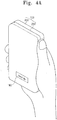
- FIGS. 4A to 4C illustrate a process of performing an unlocking action on an electronic device 100 according to an embodiment of the invention.
- the flexible touch screen 200 operates first in a lock mode and a sleep mode and displays an unlock image IMG when being touched by a user.
- the unlock image IMG may imply a direct meaning of bending.
- the unlock image IMG may include a wording such as "Bend me,” for example.
- a user presses both sides of the electronic device 100 to start an unlock action. It is determined whether a trial is made to unlock the flexible touch screen 200, based on the fact that the flexible touch screen 200 is bent, the electronic device 100 detects the bending and the user interacts with an unlock image IMG.
- the unlock action may be predefined bending to bend the electronic device 100 one or more times.
- the predefined bending may be performed two or more times to effectively prevent the electronic device 100 from being unintentionally unlocked while the user handles the electronic device 100.
- the user must bend the electronic device 100 two or more times for a predetermined time.
- the predefined bending action is performed, the electronic device 100 is unlocked and the flexible touch screen displays a user interface object associated with a general operation in the unlock state.
- FIG. 4C shows an embodiment of a user interface object displayed on the flexible touch screen 200 when the electronic device 100 operates in an unlock state.
- a user may interact with the user interface object to activate an application App 1 to App3 or a specific function Fn1 to Fn3, for example, but is not limited thereto.
- the unlock image IMG may be used to indicate failure in performing an unlock action.
- the electronic device 100 may display an unlock image IMG implying bending the electronic device 100 while allowing the user to try to perform the unlock action one more time.
- the electronic device 100 returns to a sleep mode when the bending is not detected for a predetermined time.
- FIG. 5A is a perspective view of an electronic device 101 according to another embodiment of the invention
- FIG. 5B is a cross-sectional view taken along a line I-I' in FIG. 5A .
- the electronic device 101 includes a flexible touch screen 201 and a body part 301.
- the flexible touch screen 201 and the body part 301 are different in structure compared with the flexible touch screen 200 and the flexible body part 300 described with reference to FIGS. 1 and 2 .
- the differences in structure will be specifically explained.
- Unexplained features of the flexible touch screen 201 and the body part 301 are similar to the embodiment of the flexible touch screen 200 and the flexible body part 300 described in FIGS. 1 and 2 .
- the flexible touch screen 201 is provided in a flat form.
- the flexible touch screen 201 may be bent by an external force due to its flexibility.
- the body part 301 has no flexibility.
- a mold frame (not shown) determining the appearance of the body part 301 may be made of a hard material, for example.
- the body part 301 is provided below the flexible touch screen 201. At least one side of a top surface of the body part 301 may be spaced apart from the flexible touch screen 201 in a thickness direction. In FIGS. 5A and 5B , both sides of the top surface of the body part 301 are spaced apart from the flexible touch screen 201 in the thickness direction.
- both side edge regions of the top surface of the body part 301 is provided in a curved shape.
- a spaced groove WL is formed between the both sides, e.g., edge regions, of the top surface of the body part 301 and the flexible touch screen 201.
- the electronic device 101 may further include a flexible material FM disposed at the spaced groove WL.
- the flexible material FM may be a porous flexible material.
- a left edge of the body part 301 and the flexible touch screen 201 are spaced apart from each other in the thickness direction by a left spaced distance L1.
- a right edge of the body part 301 and the flexible touch screen 201 are spaced apart from each other in the thickness direction by a right spaced distance L2.
- the left spaced distance L1 and the right spaced distance L2 are spaces for bending the flexible touch screen 201 when a user presses both sides of the flexible touch screen 201. That is, the left and right spaced distances L1 and L2 are not changed when the user does not press the flexible touch screen 201 and may be zero when the user presses both sides of the flexible touch screen 201 with a maximum force to make the top surface of the flexible touch screen 201 convex. In an embodiment, the left and right spaced distances L1 and L2 may be maximal when the user presses both sides of the flexible touch screen 201 with the maximum force to make the top surface of the flexible touch screen 201 concave.
- the electronic device 101 senses change of the left and right spaced distances L1 and L2 to detect whether the flexible touch screen 201 is bent. When the change of the left and right spaced distances L1 and L2 is greater than a predefined value, the electronic device 101 may determine that the flexible touch screen 201 is bent.
- the electronic device 101 may determine that the flexible touch screen 201 is concavely bent.
- the electronic device 101 may determine that the flexible touch screen 201 is convexly bent.
- the electronic device 101 may independently sense at least one of the change of the left spaced distance L1 and the change of the right spaced distance L2.
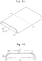
- FIG. 6A is a perspective view of an electronic device 102 according to another exemplary embodiment of the invention
- FIG. 6B is a cross-sectional view taken along a line I-I' in FIG. 6A .
- the electronic device 102 includes a flexible touch screen 202 and a body part 302.
- the body part 302 is substantially identical to the body part 301 in the embodiment explained with reference to FIGS. 5A and 5B and will not be explained in further detail.
- the flexible touch screen 202 is disposed on the body part 302.
- the flexible touch screen 202 may include a left area ST1, a middle area ST2 and a right area ST3. Although the flexible touch screen 202 are divided into the left area ST1, the middle area ST2 and the right area ST3 for the convenience of explanation, the area ST1, the middle area ST2 and the right area ST3 may be integrally formed.
- the middle area ST2 is disposed between the left area ST1 and the right area ST2 and not spaced apart from the body part 302.
- the left area ST1 is provided in a curved shape along a left edge area of a top surface of the body part 302.
- the left area ST1 may be spaced apart from a left edge of the body part 302 in a width direction by a left spaced distance L3.
- the right area ST3 is provided in a curved shape along a right edge area of the top surface of the body part 302.
- the right area ST3 is spaced apart from a right edge of the body part 302 in the width direction by a right spaced distance L4.
- a spaced groove WL is formed between the left edge area of the top surface of the body part 302 and the left area ST1 and between the right edge area of the top surface of the body part 302 and the right area ST3.
- the electronic device 102 may further include a flexible material FM disposed at the spaced groove WL.
- the flexible material FM may be a porous flexible material.
- the electronic device 102 senses changes of the left and right spaced distances L3 and L4 to detect whether the flexible touch screen 202 is bent. When the change of the left and right spaced distances L3 and L4 is greater than a predefined value, the electronic device 102 may determine that the flexible touch screen 202 is bent.
- the electronic device 102 may determine that the flexible touch screen 202 is concavely bent.
- the electronic device 102 may determine that the flexible touch screen 202 is convexly bent.
- the electronic device 102 may independently sense at least one of the change of the left spaced distance L3 and the change of the right spaced distance L4.
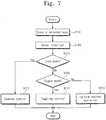
- FIG. 7 is a flowchart illustrating a zooming control method based on a bending action in an electronic device according to embodiments of the invention.
- the electronic device executes a selected mode (S101).
- the selected mode indicates an application that requires an object image to be displayed.
- the selected mode may be a web page display mode in a web browser function or environment, a photo data display mode in a camera function or environment or a text display mode in a text viewer function or environment, for example.
- a target image is displayed on a flexible touch screen in a visual form.
- the electronic device senses occurrence of interrupt (S103).
- the interrupt indicates a signal or instruction input through a touch screen or a special function key by a user to stop an application under execution.
- the interrupt may be a predefined bending action.
- the predefined bending action may include, for example, a bending action in which a user bends the left side of the flexible touch screen, a bending action in which a user bends the right side of the flexible touch screen, a bending action in which a user bends the right side and the left side of the flexible touch screen, a bending action in which a user bends the flexible touch screen in a multiple bending manner, a bending action in which a user vertically bends the flexible touch screen at least once after horizontally bending the flexible touch screen at least once, a bending action in which a user vertically bends the flexible touch screen at least once, a bending action in which a user horizontally bends the flexible touch screen at least once after vertically bending the flexible touch screen at least once
- the electronic device determines whether the interrupt is to request a zoom mode (S105).
- the request for the zoom mode may be set as one of the predefined bending actions.
- the request for the zoom mode will be explained based on a fact that a flexible touch screen is bent once for a predetermined time or longer.
- the electronic device When the interrupt is to request the zoom mode, the electronic device performs zooming control of the target image according to a user input (S107). This will be explained in detail later.
- the electronic device determines whether the interrupt request a toggle mode (S109).
- the request for the toggle mode may be set not as the request for the zoom mode but as one of the predefined bending actions.
- the request for the toggle mode will be explained based on a fact that the flexible touch screen is bent successively twice.
- the electronic device When the interrupt is to request the toggle mode, the electronic device performs toggling control of the target image (S111). This will be explained in detail later.
- the electronic device When the interrupt is not to request the toggle mode, the electronic device performs another operation corresponding to the interrupt (S113). When the interrupt is to request a specific menu, for example, the electronic device displays the requested menu. In addition, when the interrupt is to select a specific icon, the electronic device performs a function assigned to the selected icon or executes an application assigned to the selected icon.
- FIG. 8 is a flowchart illustrating zooming control operations in FIG. 7 .
- the electronic device when the interrupt is to request a zoom mode, the electronic device activates the zoom mode (S211). At this point, the electronic device displays an overlay layer overlapping a target image on a flexible touch screen.
- the overlay layer is displayed to suitably receive a user input that will be explained later.
- the electronic device may also display a graphical element on the flexible touch screen such that a user intuitively recognizes activation of the zoom mode.
- the electronic device determines whether a user input based on bending is detected (S212). At this point, the electronic device may measure time until the user input is detected after activation of the zoom mode. When the user input is not detected for the predefined time, the electronic device stops the zoom mode.
- the electronic device determines whether the user input is a first bending event (S213). When the user input is not the first bending event, the electronic device determines whether the user input is a second bending event (S231). When the user input is neither the first bending event nor the second bending event, the flow proceeds to operation S212.
- the first bending event and the second bending event may be one of the defined bending actions.
- the first bending event may be to bend the flexible touch screen once
- the second bending event may be to bend the flexible touch screen twice, for example.
- the electronic device determines whether the first bending event is a zoom-in action or a zoom-out action (S215).
- the zoom-in action and the zoom-out action may be different from each other while being compatible with the first bending event.
- the zoom-in action may be to bend both sides of the flexible touch screen once for a predetermined time or longer, and the zoom-out action may be to bend both sides of the flexible touch screen for a time shorter than the predetermined time, for example.
- the zoom-in and zoom-out actions are not limited thereto, and the zoom-in action may be to convexly bend the flexible touch screen and the zoom-out action may be to concavely bend the flexible touch screen.
- the zoom-in action may be to horizontally bend the flexible touch screen once and the zoom-out action may be to vertically bend the flexible touch screen once. That is, any two bending actions may be set as the zoom-in action and the zoom-out action, respectively.
- the electronic device zooms in the target image during the zoom-in action (S219).
- an image displayed on a middle of the flexible touch screen may be a center point of the zoom-in action.
- a zoom-in ratio of the target image may be in proportion to a time when the flexible touch screen is released from the zoom-in action.
- the electronic device zooms out the target image during the zoom-out action (S221).
- an image displayed on a middle of the flexible touch screen may be a center point of the zoom-out action.
- a zoom-out ratio of the target image may be in proportion to a time when the flexible touch screen is released from the zoom-out action.
- the electronic device determines whether the flexible touch screen is released from the first bending event (S223).
- the electronic device holds the zoomed-in or zoomed-out target image until the flexible touch screen is released from the first bending event (S225).
- the electronic device When the user input is the second bending event, the electronic device provides the target image with a predefined default size (S233). That is, the electronic device converts the zoomed-in or zoom-out target image into a default-sized image prior to zoom-in or zoom-out.
- the second bending event may be set to successively bend the flexible touch screen twice within a predetermined time.
- FIG. 9 is a flowchart illustrating toggling control operations in FIG. 7 .
- the electronic device checks a current scale factor of a target image displayed on the flexible touch screen (S301). That is, the electronic device finds out a ratio of a current size of the target image to a default size of the target image.
- the electronic device determines whether the current scale factor is greater than or equal to a predefined default scale factor (S303).
- the predefined default scale factor is a specific scale factor that is commonly used when the electronic device displays the target image.
- the electronic device zooms out the target image depending on a zoom-out ratio (S305).
- the electronic device displays the zoomed-out target image on the flexible touch screen (S307). That is, when receiving an interrupt to request a toggle mode while the target image is displayed at a specific scale factor that is equal to or greater than the default scale factor, the electronic device scales down the target image.
- the scaling down of the target image complies with the zoom-out ratio.
- the electronic device may obtain an effect to provide a preview image through toggling control.
- the electronic device may zoom out the text page at a minimum scale factor according to a toggle mode request to display the entire text page.
- the electronic device determines whether there is a request to stop a toggle mode while displaying the zoomed-out target image (S313).
- the electronic device displays the zoomed-out target image after converting the zoomed-out target image into a conversion-sized target image (S315).
- the conversion size may be any one of a size before the target image is zoomed in or out, a size of a target image to which the default scale factor is applied and a size of the zoomed-in or zoomed-out target image.
- the electronic device displays the target image after converting the target image at the current scale factor detected in operation S301.
- the conversion is not limited thereto, and the electronic device may display the zoomed-out target image after converting the zoomed-out target image at the default scale factor or may display the zoomed-out target image without conversion.
- the electronic device determines whether there is a request for the toggle mode (S317).
- the operation S317 is substantially identical to the operation S109 in FIG. 7 and will not be explained in further detail.
- the electronic device When there is a request for the toggle mode, the electronic device proceeds to the operation S301. After returning to the operation S301, the electronic device proceeds to operation S309 through the operation S303. That is, since the target image is zoomed out through the operations S305 and 307, the current scale factor of the target image may be smaller than the default scale factor at the operation S303. In this case, the electronic device proceeds to operations S309 and S311 to perform an operation of zooming in the target image.
- the electronic device may restore the zoomed-out target image at a default scale factor or zoom in the zoomed-out target image at a scale factor greater than the default scale factor.
- the electronic device zooms in the target image according to a zoom-in ratio (S309).
- the electronic device displays the zoomed-in target image on the flexible touch screen (S311). That is, when receiving an interrupt to request the toggle mode while the target image is displayed at a specific scale factor smaller than the default scale factor, the electronic device scales up the target image.
- the scaling up of the target image complies with the zoom-in ratio.
- the electronic device may have an effect to use a magnifying glass through toggling control.
- the electronic device zooms in the page of document at a maximum scale factor according to a toggle mode request to display a part of the page of document.
- the electronic device determines whether there is a request to stop the toggle mode (S313).
- the conversion size may be any one of a size before the target image is zoomed in or out, a size of a target image to which the default scale factor is applied and a size of the zoomed-in or zoomed-out target image.
- the electronic device determines whether there is a request for the toggle mode (S317).
- the electronic device proceeds to operation S305 through the operation S303. After returning to the operation S301, the electronic device proceeds to the operation S305 through the operation S303. That is, since the target image is zoomed in through the operations S309 and S311, the current scale factor of the target image may be greater than or equal to the default scale factor. In this case, the electronic device may proceed to the operations S305 and S307 to perform an operation of zooming out the target image.
- the electronic device may restore the zoomed-in target image at a default scale factor or zooms out the target image at a scale factor smaller than the default scale factor according to a request for second toggle mode.
- the electronic device may perform another operation (S319).
- the another operation may be different from the zooming control and the toggling control.
- the another operation may be, for example, that the electron device displays a requested menu, executes a function assigned to a specific icon or executes an application assigned to the specific icon.
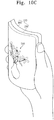
- FIGS. 10A to 10C illustrate a zooming control process in an electronic device 100 according to an embodiment of the invention.
- the electronic device 100 displays a target image TI of specific contents in a selected mode.
- specific image data displayed under an image viewer environment is shown as an embodiment of the target image TI.
- a user bends a flexible touch screen 200 once by pressing both sides of the electronic device 100 to activate a zoom mode.
- the electronic device 100 may display an overlay layer OV overlapping the target image.
- the electronic device 100 may display a selectable zooming operation and a graphical element GI for instructing the zooming operation.
- the overlay layer OV and the graphical element GI may be optional according to user's setting.
- the electronic device 100 receives a zoom-in or zoom-out action from a user to zoom in or out the target image TI.
- FIG. 10C shows an embodiment where the user convexly bend the flexible touch screen 200 to display a zoomed-in target image TI0 on the flexible touch screen 200 when the zoom-in action is set to convexly bend the flexible touch screen 200.
- FIGS. 11A to 11C illustrate a toggling control process in an electronic device 100 according to an embodiment of the invention.
- the electronic device 100 displays a target image TI of specific contents in a selected mode.
- specific image data displayed under an image viewer environment is shown as an embodiment of the target image TI.
- a user bends a flexible touch screen 200 twice by successively both sides of the electronic device 100 to perform first toggling control on the target image TI.
- the electronic device 100 zooms out the target image TI according to a zoom-out ratio when a current scale factor of the target image TI is greater than or equal to a default scale factor.
- FIG. 11B shows an embodiment where the flexible touch screen 200 displays a zoomed-out target image TI1.
- the user bends the flexible touch screen 200 twice by successively pressing both sides of the electronic device 100 to perform second toggling control on the zoomed-out target image TI1. Since the target image TI1 is zoomed out by the first toggling control in FIG. 11B , a current scale factor of the zoomed-out target image TI1 may be smaller than a default scale factor.
- the electronic device 100 zooms in the zoomed-out target image TI1 at a zoom-in ratio.
- the electronic device 100 may display the zoomed-out target image TI1 at any one of the default scale factor or a scale factor greater than the default scale factor.
- FIG. 11C shows an embodiment where the flexible touch screen 200 displays a zoomed-in target image TI2.
- an electronic device can be unlocked by bending using flexibility of a flexible touch screen.
- an electronic device can be unlocked not only when the electronic device is flexible but also when some components of the electronic device are not flexible.
- zooming control and toggling control of a target image can be performed based on a bending action.
Landscapes
- Engineering & Computer Science (AREA)
- Theoretical Computer Science (AREA)
- General Engineering & Computer Science (AREA)
- Human Computer Interaction (AREA)
- Physics & Mathematics (AREA)
- General Physics & Mathematics (AREA)
- Computer Hardware Design (AREA)
- Signal Processing (AREA)
- User Interface Of Digital Computer (AREA)
Claims (9)
- Dispositif électronique (100) comprenant :
un écran tactile flexible (201, 202) qui présente une flexibilité, incluant une forme sensiblement plane, et incluant :une unité d'affichage (210) qui est configurée de manière à ce qu'elle affiche une image ; etune unité de flexion (230) qui est configurée de manière à ce qu'elle détecte une entrée de flexion d'utilisateur ; etune partie de corps (301, 302) qui est disposée au-dessous de l'écran tactile flexible (201, 202), dans lequel la partie de corps (301, 302) inclut :un contrôleur (310) qui est configuré de manière à ce qu'il commande une transition depuis un état de verrouillage jusqu'à un état de déverrouillage de l'écran tactile flexible (201, 202) sur la base de l'entrée de flexion d'utilisateur ; etune mémoire (320) qui est configurée de manière à ce qu'elle stocke une action de flexion prédéfinie qui est utilisée pour réaliser une transition depuis l'état de verrouillage jusqu'à l'état de déverrouillage de l'écran tactile flexible (201, 202) ;caractérisé en ce que :la partie de corps (301, 302) ne présente pas de flexibilité ;au moins un côté de la surface supérieure de la partie de corps (301, 302) est incurvé, dans lequel une gorge d'espacement (WL) est formée dans une direction d'épaisseur entre l'au moins un côté de la surface supérieure de la partie de corps (301, 302) et l'écran tactile flexible (201, 202) ; et en ce que :
le dispositif électronique inclut en outre un matériau flexible (FM) qui est disposé au niveau de la gorge d'espacement (WL). - Dispositif électronique tel que revendiqué selon la revendication 1, dans lequel l'unité de flexion (230) est configurée de manière à ce qu'elle détecte l'entrée de flexion d'utilisateur en détectant une variation d'une distance d'espacement de la direction d'épaisseur entre l'au moins un côté de la surface supérieure de la partie de corps (301, 302) et l'écran tactile flexible (201, 202).
- Dispositif électronique tel que revendiqué selon la revendication 1 ou 2, dans lequel l'au moins un côté de la surface supérieure de la partie de corps (302) est espacé de l'écran tactile flexible dans au moins une direction prise parmi une direction de largeur et une direction de longueur, au moins un côté (ST1, ST2) de l'écran tactile flexible (202) qui correspond à l'au moins un côté de la surface supérieure de la partie de corps (302) est incurvé le long de l'au moins un côté de la surface supérieure de la partie de corps.
- Dispositif électronique tel que revendiqué selon la revendication 3, dans lequel l'unité de flexion (230) est configurée de manière à ce qu'elle détecte l'entrée de flexion d'utilisateur en détectant une variation d'une distance d'espacement d'au moins une direction prise parmi la direction de largeur et la direction de longueur entre l'au moins un côté de la surface supérieure de la partie de corps (302) et l'au moins un côté de l'écran tactile flexible (202).
- Dispositif électronique tel que revendiqué selon l'une quelconque des revendications qui précèdent, dans lequel l'action de flexion prédéfinie inclut au moins une flexion prise parmi la flexion de l'écran tactile flexible (201, 202) une seule fois et la flexion de l'écran tactile flexible deux fois ou plus.
- Dispositif électronique tel que revendiqué selon la revendication 5, dans lequel la flexion de l'écran tactile flexible (201, 202) deux fois ou plus inclut au moins une flexion prise parmi la flexion de l'écran tactile flexible (201, 202) deux fois ou plus dans une même direction et la flexion de l'écran tactile flexible deux fois ou plus dans des directions différentes.
- Dispositif électronique tel que revendiqué selon l'une quelconque des revendications qui précèdent, dans lequel l'action de flexion prédéfinie inclut au moins une flexion prise parmi une flexion de façon concave de l'écran tactile flexible (201, 202) et une flexion de façon convexe de l'écran tactile flexible.
- Dispositif électronique tel que revendiqué selon l'une quelconque des revendications qui précèdent, dans lequel le contrôleur (310) est configuré de manière à ce qu'il permette que l'écran tactile flexible (201, 202) réalise une transition depuis l'état de verrouillage jusqu'à l'état de déverrouillage, lorsque l'entrée de flexion d'utilisateur correspond à l'action de flexion prédéfinie et est configuré de manière à ce qu'il permette que l'écran tactile flexible (201, 202) reste dans l'état de verrouillage, lorsque l'entrée de flexion d'utilisateur ne correspond pas à l'action de flexion prédéfinie.
- Dispositif électronique tel que revendiqué selon l'une quelconque des revendications qui précèdent, dans lequel l'écran tactile flexible (201, 202) est configuré de manière à ce qu'il affiche un repère visuel pour l'action de flexion prédéfinie lors d'un actionnement dans l'état de verrouillage.
Applications Claiming Priority (1)
| Application Number | Priority Date | Filing Date | Title |
|---|---|---|---|
| KR1020130058597A KR102145504B1 (ko) | 2013-05-23 | 2013-05-23 | 전자 장치, 전자 장치의 잠금 해제 방법, 및 전자 장치의 주밍 및 토글링 제어 방법 |
Publications (2)
| Publication Number | Publication Date |
|---|---|
| EP2806331A1 EP2806331A1 (fr) | 2014-11-26 |
| EP2806331B1 true EP2806331B1 (fr) | 2019-01-16 |
Family
ID=50774616
Family Applications (1)
| Application Number | Title | Priority Date | Filing Date |
|---|---|---|---|
| EP14162777.8A Active EP2806331B1 (fr) | 2013-05-23 | 2014-03-31 | Appareil électronique et méthode de déverrouillage correspondante |
Country Status (3)
| Country | Link |
|---|---|
| US (1) | US9146638B2 (fr) |
| EP (1) | EP2806331B1 (fr) |
| KR (1) | KR102145504B1 (fr) |
Families Citing this family (16)
| Publication number | Priority date | Publication date | Assignee | Title |
|---|---|---|---|---|
| USD763848S1 (en) * | 2014-07-08 | 2016-08-16 | Lg Electronics Inc. | Tablet computer |
| USD763849S1 (en) * | 2014-07-08 | 2016-08-16 | Lg Electronics Inc. | Tablet computer |
| USD796499S1 (en) * | 2014-11-26 | 2017-09-05 | Samsung Electronics Co., Ltd. | Electronic device |
| US9338627B1 (en) * | 2015-01-28 | 2016-05-10 | Arati P Singh | Portable device for indicating emergency events |
| USD820801S1 (en) | 2015-11-04 | 2018-06-19 | Lenovo (Beijing) Co., Ltd. | Flexible electronic device |
| USD838270S1 (en) * | 2015-11-06 | 2019-01-15 | Samsung Display Co., Ltd. | Display device |
| CN105955534B (zh) * | 2016-05-09 | 2018-09-18 | 京东方科技集团股份有限公司 | 柔性显示模组及其制作方法 |
| USD857645S1 (en) * | 2016-08-23 | 2019-08-27 | Lg Electronics Inc. | Mobile phone |
| US10976919B2 (en) * | 2017-09-14 | 2021-04-13 | Sap Se | Hybrid gestures for visualizations |
| CN108197441A (zh) * | 2017-11-29 | 2018-06-22 | 努比亚技术有限公司 | 柔性屏终端及其解锁控制方法、计算机可读存储介质 |
| CN108363917A (zh) * | 2018-01-31 | 2018-08-03 | 努比亚技术有限公司 | 移动终端解锁方法、移动终端及计算机可读存储介质 |
| CN209419659U (zh) * | 2018-07-17 | 2019-09-20 | 华为技术有限公司 | 一种终端 |
| CN112714901B (zh) * | 2018-09-30 | 2024-03-01 | 华为技术有限公司 | 系统导航栏的显示控制方法、图形用户界面及电子设备 |
| CN110176188B (zh) * | 2019-06-26 | 2023-03-14 | 昆山国显光电有限公司 | 一种内折叠显示装置 |
| CN112671976B (zh) * | 2019-09-30 | 2023-01-13 | 华为技术有限公司 | 电子设备的控制方法、装置及电子设备、存储介质 |
| CN113923297B (zh) * | 2020-06-24 | 2025-02-07 | 中兴通讯股份有限公司 | 影像显示方法及装置、计算机可读存储介质、电子装置 |
Family Cites Families (24)
| Publication number | Priority date | Publication date | Assignee | Title |
|---|---|---|---|---|
| US6243074B1 (en) * | 1997-08-29 | 2001-06-05 | Xerox Corporation | Handedness detection for a physical manipulatory grammar |
| US6943773B2 (en) * | 2001-05-11 | 2005-09-13 | Palmone, Inc. | Page flicking mechanism for electronic display devices that paginate content |
| KR100769783B1 (ko) * | 2002-03-29 | 2007-10-24 | 가부시끼가이샤 도시바 | 표시 입력 장치 및 표시 입력 시스템 |
| US7456823B2 (en) * | 2002-06-14 | 2008-11-25 | Sony Corporation | User interface apparatus and portable information apparatus |
| JP2005174006A (ja) * | 2003-12-11 | 2005-06-30 | Canon Inc | 表示装置 |
| US7657849B2 (en) | 2005-12-23 | 2010-02-02 | Apple Inc. | Unlocking a device by performing gestures on an unlock image |
| KR100983726B1 (ko) | 2008-05-20 | 2010-09-24 | 성균관대학교산학협력단 | 측면 키 인터페이스 장치, 측면 키 인터페이스 설정 방법,및 이를 구비한 휴대 단말기 |
| KR101581275B1 (ko) | 2008-11-05 | 2015-12-31 | 엘지전자 주식회사 | 플렉서블 디스플레이를 구비하는 휴대 단말기 및 그 제어방법 |
| KR101521219B1 (ko) * | 2008-11-10 | 2015-05-18 | 엘지전자 주식회사 | 플렉서블 디스플레이를 이용하는 휴대 단말기 및 그 제어방법 |
| JP2010157060A (ja) * | 2008-12-26 | 2010-07-15 | Sony Corp | 表示装置 |
| KR101171858B1 (ko) | 2009-07-24 | 2012-08-08 | 에스케이플래닛 주식회사 | 단말기의 잠금설정 해지 시스템 및 방법 |
| KR20110055137A (ko) | 2009-11-19 | 2011-05-25 | 삼성전자주식회사 | 터치 잠금 기능 운용 방법 및 이를 이용한 휴대 단말기 |
| KR101688134B1 (ko) | 2009-12-16 | 2016-12-20 | 엘지전자 주식회사 | 사이드 터치 입력 수단을 구비한 이동단말기 및 그의 기능 수행 방법 |
| US8432368B2 (en) * | 2010-01-06 | 2013-04-30 | Qualcomm Incorporated | User interface methods and systems for providing force-sensitive input |
| US8339360B2 (en) * | 2010-06-02 | 2012-12-25 | International Business Machines Corporation | Flexible display security CAPTCHA bends |
| KR101664418B1 (ko) * | 2010-11-25 | 2016-10-10 | 엘지전자 주식회사 | 이동 단말기 |
| WO2012135935A2 (fr) | 2011-04-06 | 2012-10-11 | Research In Motion Limited | Dispositif électronique portable avec reconnaissance de gestes et son procédé de commande |
| KR101320384B1 (ko) * | 2011-06-30 | 2013-10-23 | 삼성디스플레이 주식회사 | 가요성 표시 패널 및 상기 가요성 표시 패널을 포함하는 표시 장치 |
| US8787016B2 (en) | 2011-07-06 | 2014-07-22 | Apple Inc. | Flexible display devices |
| US8929085B2 (en) * | 2011-09-30 | 2015-01-06 | Apple Inc. | Flexible electronic devices |
| EP2660678A1 (fr) | 2012-05-03 | 2013-11-06 | LG Electronics Inc. | Terminal mobile et procédé de contrôle du terminal mobile |
| KR101978206B1 (ko) * | 2012-06-29 | 2019-05-14 | 엘지전자 주식회사 | 이동 단말기 |
| US9195108B2 (en) * | 2012-08-21 | 2015-11-24 | Apple Inc. | Displays with bent signal lines |
| KR102042556B1 (ko) * | 2012-09-05 | 2019-11-11 | 엘지전자 주식회사 | 이동 단말기 및 이동 단말기의 제어 방법 |
-
2013
- 2013-05-23 KR KR1020130058597A patent/KR102145504B1/ko active Active
- 2013-10-24 US US14/062,034 patent/US9146638B2/en active Active
-
2014
- 2014-03-31 EP EP14162777.8A patent/EP2806331B1/fr active Active
Non-Patent Citations (1)
| Title |
|---|
| None * |
Also Published As
| Publication number | Publication date |
|---|---|
| US20140347286A1 (en) | 2014-11-27 |
| EP2806331A1 (fr) | 2014-11-26 |
| US9146638B2 (en) | 2015-09-29 |
| KR20140137737A (ko) | 2014-12-03 |
| KR102145504B1 (ko) | 2020-08-19 |
Similar Documents
| Publication | Publication Date | Title |
|---|---|---|
| EP2806331B1 (fr) | Appareil électronique et méthode de déverrouillage correspondante | |
| EP2433203B1 (fr) | Dispositif portable à sélection et transformation d'éléments actifs déclenchés par un toucher à deux doigts | |
| CN104220963B (zh) | 柔性显示设备及其操作方法 | |
| JP5189197B1 (ja) | 携帯情報端末 | |
| KR20160046139A (ko) | 디스플레이 장치 및 그 디스플레이 방법 | |
| JP2014102557A (ja) | 携帯端末 | |
| JP2009218995A (ja) | 携帯端末装置 |
Legal Events
| Date | Code | Title | Description |
|---|---|---|---|
| PUAI | Public reference made under article 153(3) epc to a published international application that has entered the european phase |
Free format text: ORIGINAL CODE: 0009012 |
|
| 17P | Request for examination filed |
Effective date: 20140331 |
|
| AK | Designated contracting states |
Kind code of ref document: A1 Designated state(s): AL AT BE BG CH CY CZ DE DK EE ES FI FR GB GR HR HU IE IS IT LI LT LU LV MC MK MT NL NO PL PT RO RS SE SI SK SM TR |
|
| AX | Request for extension of the european patent |
Extension state: BA ME |
|
| RAP1 | Party data changed (applicant data changed or rights of an application transferred) |
Owner name: SAMSUNG DISPLAY CO., LTD. |
|
| REG | Reference to a national code |
Ref country code: DE Ref legal event code: R079 Ref document number: 602014039897 Country of ref document: DE Free format text: PREVIOUS MAIN CLASS: G06F0001160000 Ipc: G06F0003048700 |
|
| GRAP | Despatch of communication of intention to grant a patent |
Free format text: ORIGINAL CODE: EPIDOSNIGR1 |
|
| STAA | Information on the status of an ep patent application or granted ep patent |
Free format text: STATUS: GRANT OF PATENT IS INTENDED |
|
| RIC1 | Information provided on ipc code assigned before grant |
Ipc: G06F 3/0487 20130101AFI20180711BHEP Ipc: G06F 3/01 20060101ALI20180711BHEP Ipc: G06F 1/16 20060101ALI20180711BHEP Ipc: H04M 1/02 20060101ALI20180711BHEP |
|
| INTG | Intention to grant announced |
Effective date: 20180725 |
|
| GRAS | Grant fee paid |
Free format text: ORIGINAL CODE: EPIDOSNIGR3 |
|
| GRAA | (expected) grant |
Free format text: ORIGINAL CODE: 0009210 |
|
| STAA | Information on the status of an ep patent application or granted ep patent |
Free format text: STATUS: THE PATENT HAS BEEN GRANTED |
|
| AK | Designated contracting states |
Kind code of ref document: B1 Designated state(s): AL AT BE BG CH CY CZ DE DK EE ES FI FR GB GR HR HU IE IS IT LI LT LU LV MC MK MT NL NO PL PT RO RS SE SI SK SM TR |
|
| REG | Reference to a national code |
Ref country code: GB Ref legal event code: FG4D |
|
| REG | Reference to a national code |
Ref country code: CH Ref legal event code: EP |
|
| REG | Reference to a national code |
Ref country code: IE Ref legal event code: FG4D |
|
| REG | Reference to a national code |
Ref country code: DE Ref legal event code: R096 Ref document number: 602014039897 Country of ref document: DE |
|
| REG | Reference to a national code |
Ref country code: AT Ref legal event code: REF Ref document number: 1090202 Country of ref document: AT Kind code of ref document: T Effective date: 20190215 |
|
| REG | Reference to a national code |
Ref country code: NL Ref legal event code: FP |
|
| REG | Reference to a national code |
Ref country code: LT Ref legal event code: MG4D |
|
| REG | Reference to a national code |
Ref country code: AT Ref legal event code: MK05 Ref document number: 1090202 Country of ref document: AT Kind code of ref document: T Effective date: 20190116 |
|
| PG25 | Lapsed in a contracting state [announced via postgrant information from national office to epo] |
Ref country code: ES Free format text: LAPSE BECAUSE OF FAILURE TO SUBMIT A TRANSLATION OF THE DESCRIPTION OR TO PAY THE FEE WITHIN THE PRESCRIBED TIME-LIMIT Effective date: 20190116 Ref country code: NO Free format text: LAPSE BECAUSE OF FAILURE TO SUBMIT A TRANSLATION OF THE DESCRIPTION OR TO PAY THE FEE WITHIN THE PRESCRIBED TIME-LIMIT Effective date: 20190416 Ref country code: PT Free format text: LAPSE BECAUSE OF FAILURE TO SUBMIT A TRANSLATION OF THE DESCRIPTION OR TO PAY THE FEE WITHIN THE PRESCRIBED TIME-LIMIT Effective date: 20190516 Ref country code: SE Free format text: LAPSE BECAUSE OF FAILURE TO SUBMIT A TRANSLATION OF THE DESCRIPTION OR TO PAY THE FEE WITHIN THE PRESCRIBED TIME-LIMIT Effective date: 20190116 Ref country code: FI Free format text: LAPSE BECAUSE OF FAILURE TO SUBMIT A TRANSLATION OF THE DESCRIPTION OR TO PAY THE FEE WITHIN THE PRESCRIBED TIME-LIMIT Effective date: 20190116 Ref country code: LT Free format text: LAPSE BECAUSE OF FAILURE TO SUBMIT A TRANSLATION OF THE DESCRIPTION OR TO PAY THE FEE WITHIN THE PRESCRIBED TIME-LIMIT Effective date: 20190116 Ref country code: PL Free format text: LAPSE BECAUSE OF FAILURE TO SUBMIT A TRANSLATION OF THE DESCRIPTION OR TO PAY THE FEE WITHIN THE PRESCRIBED TIME-LIMIT Effective date: 20190116 |
|
| PG25 | Lapsed in a contracting state [announced via postgrant information from national office to epo] |
Ref country code: GR Free format text: LAPSE BECAUSE OF FAILURE TO SUBMIT A TRANSLATION OF THE DESCRIPTION OR TO PAY THE FEE WITHIN THE PRESCRIBED TIME-LIMIT Effective date: 20190417 Ref country code: BG Free format text: LAPSE BECAUSE OF FAILURE TO SUBMIT A TRANSLATION OF THE DESCRIPTION OR TO PAY THE FEE WITHIN THE PRESCRIBED TIME-LIMIT Effective date: 20190416 Ref country code: HR Free format text: LAPSE BECAUSE OF FAILURE TO SUBMIT A TRANSLATION OF THE DESCRIPTION OR TO PAY THE FEE WITHIN THE PRESCRIBED TIME-LIMIT Effective date: 20190116 Ref country code: IS Free format text: LAPSE BECAUSE OF FAILURE TO SUBMIT A TRANSLATION OF THE DESCRIPTION OR TO PAY THE FEE WITHIN THE PRESCRIBED TIME-LIMIT Effective date: 20190516 Ref country code: RS Free format text: LAPSE BECAUSE OF FAILURE TO SUBMIT A TRANSLATION OF THE DESCRIPTION OR TO PAY THE FEE WITHIN THE PRESCRIBED TIME-LIMIT Effective date: 20190116 Ref country code: LV Free format text: LAPSE BECAUSE OF FAILURE TO SUBMIT A TRANSLATION OF THE DESCRIPTION OR TO PAY THE FEE WITHIN THE PRESCRIBED TIME-LIMIT Effective date: 20190116 |
|
| REG | Reference to a national code |
Ref country code: DE Ref legal event code: R097 Ref document number: 602014039897 Country of ref document: DE |
|
| PG25 | Lapsed in a contracting state [announced via postgrant information from national office to epo] |
Ref country code: SK Free format text: LAPSE BECAUSE OF FAILURE TO SUBMIT A TRANSLATION OF THE DESCRIPTION OR TO PAY THE FEE WITHIN THE PRESCRIBED TIME-LIMIT Effective date: 20190116 Ref country code: CZ Free format text: LAPSE BECAUSE OF FAILURE TO SUBMIT A TRANSLATION OF THE DESCRIPTION OR TO PAY THE FEE WITHIN THE PRESCRIBED TIME-LIMIT Effective date: 20190116 Ref country code: RO Free format text: LAPSE BECAUSE OF FAILURE TO SUBMIT A TRANSLATION OF THE DESCRIPTION OR TO PAY THE FEE WITHIN THE PRESCRIBED TIME-LIMIT Effective date: 20190116 Ref country code: EE Free format text: LAPSE BECAUSE OF FAILURE TO SUBMIT A TRANSLATION OF THE DESCRIPTION OR TO PAY THE FEE WITHIN THE PRESCRIBED TIME-LIMIT Effective date: 20190116 Ref country code: AT Free format text: LAPSE BECAUSE OF FAILURE TO SUBMIT A TRANSLATION OF THE DESCRIPTION OR TO PAY THE FEE WITHIN THE PRESCRIBED TIME-LIMIT Effective date: 20190116 Ref country code: DK Free format text: LAPSE BECAUSE OF FAILURE TO SUBMIT A TRANSLATION OF THE DESCRIPTION OR TO PAY THE FEE WITHIN THE PRESCRIBED TIME-LIMIT Effective date: 20190116 Ref country code: IT Free format text: LAPSE BECAUSE OF FAILURE TO SUBMIT A TRANSLATION OF THE DESCRIPTION OR TO PAY THE FEE WITHIN THE PRESCRIBED TIME-LIMIT Effective date: 20190116 Ref country code: MC Free format text: LAPSE BECAUSE OF FAILURE TO SUBMIT A TRANSLATION OF THE DESCRIPTION OR TO PAY THE FEE WITHIN THE PRESCRIBED TIME-LIMIT Effective date: 20190116 Ref country code: AL Free format text: LAPSE BECAUSE OF FAILURE TO SUBMIT A TRANSLATION OF THE DESCRIPTION OR TO PAY THE FEE WITHIN THE PRESCRIBED TIME-LIMIT Effective date: 20190116 |
|
| REG | Reference to a national code |
Ref country code: CH Ref legal event code: PL |
|
| PLBE | No opposition filed within time limit |
Free format text: ORIGINAL CODE: 0009261 |
|
| STAA | Information on the status of an ep patent application or granted ep patent |
Free format text: STATUS: NO OPPOSITION FILED WITHIN TIME LIMIT |
|
| PG25 | Lapsed in a contracting state [announced via postgrant information from national office to epo] |
Ref country code: LU Free format text: LAPSE BECAUSE OF NON-PAYMENT OF DUE FEES Effective date: 20190331 Ref country code: SM Free format text: LAPSE BECAUSE OF FAILURE TO SUBMIT A TRANSLATION OF THE DESCRIPTION OR TO PAY THE FEE WITHIN THE PRESCRIBED TIME-LIMIT Effective date: 20190116 |
|
| REG | Reference to a national code |
Ref country code: BE Ref legal event code: MM Effective date: 20190331 |
|
| 26N | No opposition filed |
Effective date: 20191017 |
|
| PG25 | Lapsed in a contracting state [announced via postgrant information from national office to epo] |
Ref country code: IE Free format text: LAPSE BECAUSE OF NON-PAYMENT OF DUE FEES Effective date: 20190331 Ref country code: CH Free format text: LAPSE BECAUSE OF NON-PAYMENT OF DUE FEES Effective date: 20190331 Ref country code: LI Free format text: LAPSE BECAUSE OF NON-PAYMENT OF DUE FEES Effective date: 20190331 |
|
| PG25 | Lapsed in a contracting state [announced via postgrant information from national office to epo] |
Ref country code: SI Free format text: LAPSE BECAUSE OF FAILURE TO SUBMIT A TRANSLATION OF THE DESCRIPTION OR TO PAY THE FEE WITHIN THE PRESCRIBED TIME-LIMIT Effective date: 20190116 Ref country code: BE Free format text: LAPSE BECAUSE OF NON-PAYMENT OF DUE FEES Effective date: 20190331 |
|
| PG25 | Lapsed in a contracting state [announced via postgrant information from national office to epo] |
Ref country code: TR Free format text: LAPSE BECAUSE OF FAILURE TO SUBMIT A TRANSLATION OF THE DESCRIPTION OR TO PAY THE FEE WITHIN THE PRESCRIBED TIME-LIMIT Effective date: 20190116 |
|
| PG25 | Lapsed in a contracting state [announced via postgrant information from national office to epo] |
Ref country code: MT Free format text: LAPSE BECAUSE OF NON-PAYMENT OF DUE FEES Effective date: 20190331 |
|
| PG25 | Lapsed in a contracting state [announced via postgrant information from national office to epo] |
Ref country code: CY Free format text: LAPSE BECAUSE OF FAILURE TO SUBMIT A TRANSLATION OF THE DESCRIPTION OR TO PAY THE FEE WITHIN THE PRESCRIBED TIME-LIMIT Effective date: 20190116 |
|
| PG25 | Lapsed in a contracting state [announced via postgrant information from national office to epo] |
Ref country code: HU Free format text: LAPSE BECAUSE OF FAILURE TO SUBMIT A TRANSLATION OF THE DESCRIPTION OR TO PAY THE FEE WITHIN THE PRESCRIBED TIME-LIMIT; INVALID AB INITIO Effective date: 20140331 |
|
| PG25 | Lapsed in a contracting state [announced via postgrant information from national office to epo] |
Ref country code: MK Free format text: LAPSE BECAUSE OF FAILURE TO SUBMIT A TRANSLATION OF THE DESCRIPTION OR TO PAY THE FEE WITHIN THE PRESCRIBED TIME-LIMIT Effective date: 20190116 |
|
| P01 | Opt-out of the competence of the unified patent court (upc) registered |
Effective date: 20230515 |
|
| PGFP | Annual fee paid to national office [announced via postgrant information from national office to epo] |
Ref country code: NL Payment date: 20260220 Year of fee payment: 13 |
|
| PGFP | Annual fee paid to national office [announced via postgrant information from national office to epo] |
Ref country code: GB Payment date: 20260224 Year of fee payment: 13 |
|
| PGFP | Annual fee paid to national office [announced via postgrant information from national office to epo] |
Ref country code: DE Payment date: 20260220 Year of fee payment: 13 |
|
| PGFP | Annual fee paid to national office [announced via postgrant information from national office to epo] |
Ref country code: FR Payment date: 20260224 Year of fee payment: 13 |