EP2806251A2 - Fiber optic position sensor and method for using - Google Patents
Fiber optic position sensor and method for using Download PDFInfo
- Publication number
- EP2806251A2 EP2806251A2 EP14168256.7A EP14168256A EP2806251A2 EP 2806251 A2 EP2806251 A2 EP 2806251A2 EP 14168256 A EP14168256 A EP 14168256A EP 2806251 A2 EP2806251 A2 EP 2806251A2
- Authority
- EP
- European Patent Office
- Prior art keywords
- light beam
- optical fiber
- plunger
- frame
- reverse direction
- Prior art date
- Legal status (The legal status is an assumption and is not a legal conclusion. Google has not performed a legal analysis and makes no representation as to the accuracy of the status listed.)
- Granted
Links
Images

Classifications
-
- G—PHYSICS
- G01—MEASURING; TESTING
- G01B—MEASURING LENGTH, THICKNESS OR SIMILAR LINEAR DIMENSIONS; MEASURING ANGLES; MEASURING AREAS; MEASURING IRREGULARITIES OF SURFACES OR CONTOURS
- G01B11/00—Measuring arrangements characterised by the use of optical techniques
- G01B11/14—Measuring arrangements characterised by the use of optical techniques for measuring distance or clearance between spaced objects or spaced apertures
-
- G—PHYSICS
- G01—MEASURING; TESTING
- G01D—MEASURING NOT SPECIALLY ADAPTED FOR A SPECIFIC VARIABLE; ARRANGEMENTS FOR MEASURING TWO OR MORE VARIABLES NOT COVERED IN A SINGLE OTHER SUBCLASS; TARIFF METERING APPARATUS; MEASURING OR TESTING NOT OTHERWISE PROVIDED FOR
- G01D5/00—Mechanical means for transferring the output of a sensing member; Means for converting the output of a sensing member to another variable where the form or nature of the sensing member does not constrain the means for converting; Transducers not specially adapted for a specific variable
- G01D5/26—Mechanical means for transferring the output of a sensing member; Means for converting the output of a sensing member to another variable where the form or nature of the sensing member does not constrain the means for converting; Transducers not specially adapted for a specific variable characterised by optical transfer means, i.e. using infrared, visible, or ultraviolet light
- G01D5/268—Mechanical means for transferring the output of a sensing member; Means for converting the output of a sensing member to another variable where the form or nature of the sensing member does not constrain the means for converting; Transducers not specially adapted for a specific variable characterised by optical transfer means, i.e. using infrared, visible, or ultraviolet light using optical fibres
-
- G—PHYSICS
- G01—MEASURING; TESTING
- G01D—MEASURING NOT SPECIALLY ADAPTED FOR A SPECIFIC VARIABLE; ARRANGEMENTS FOR MEASURING TWO OR MORE VARIABLES NOT COVERED IN A SINGLE OTHER SUBCLASS; TARIFF METERING APPARATUS; MEASURING OR TESTING NOT OTHERWISE PROVIDED FOR
- G01D5/00—Mechanical means for transferring the output of a sensing member; Means for converting the output of a sensing member to another variable where the form or nature of the sensing member does not constrain the means for converting; Transducers not specially adapted for a specific variable
- G01D5/26—Mechanical means for transferring the output of a sensing member; Means for converting the output of a sensing member to another variable where the form or nature of the sensing member does not constrain the means for converting; Transducers not specially adapted for a specific variable characterised by optical transfer means, i.e. using infrared, visible, or ultraviolet light
- G01D5/32—Mechanical means for transferring the output of a sensing member; Means for converting the output of a sensing member to another variable where the form or nature of the sensing member does not constrain the means for converting; Transducers not specially adapted for a specific variable characterised by optical transfer means, i.e. using infrared, visible, or ultraviolet light with attenuation or whole or partial obturation of beams of light
- G01D5/34—Mechanical means for transferring the output of a sensing member; Means for converting the output of a sensing member to another variable where the form or nature of the sensing member does not constrain the means for converting; Transducers not specially adapted for a specific variable characterised by optical transfer means, i.e. using infrared, visible, or ultraviolet light with attenuation or whole or partial obturation of beams of light the beams of light being detected by photocells
- G01D5/342—Mechanical means for transferring the output of a sensing member; Means for converting the output of a sensing member to another variable where the form or nature of the sensing member does not constrain the means for converting; Transducers not specially adapted for a specific variable characterised by optical transfer means, i.e. using infrared, visible, or ultraviolet light with attenuation or whole or partial obturation of beams of light the beams of light being detected by photocells the sensed object being the obturating part
-
- G—PHYSICS
- G02—OPTICS
- G02B—OPTICAL ELEMENTS, SYSTEMS OR APPARATUS
- G02B6/00—Light guides; Structural details of arrangements comprising light guides and other optical elements, e.g. couplings
- G02B6/24—Coupling light guides
- G02B6/26—Optical coupling means
- G02B6/35—Optical coupling means having switching means
- G02B6/351—Optical coupling means having switching means involving stationary waveguides with moving interposed optical elements
- G02B6/3512—Optical coupling means having switching means involving stationary waveguides with moving interposed optical elements the optical element being reflective, e.g. mirror
- G02B6/3514—Optical coupling means having switching means involving stationary waveguides with moving interposed optical elements the optical element being reflective, e.g. mirror the reflective optical element moving along a line so as to translate into and out of the beam path, i.e. across the beam path
-
- G—PHYSICS
- G02—OPTICS
- G02B—OPTICAL ELEMENTS, SYSTEMS OR APPARATUS
- G02B6/00—Light guides; Structural details of arrangements comprising light guides and other optical elements, e.g. couplings
- G02B6/24—Coupling light guides
- G02B6/26—Optical coupling means
- G02B6/35—Optical coupling means having switching means
- G02B6/354—Switching arrangements, i.e. number of input/output ports and interconnection types
- G02B6/3544—2D constellations, i.e. with switching elements and switched beams located in a plane
- G02B6/3548—1xN switch, i.e. one input and a selectable single output of N possible outputs
- G02B6/3552—1x1 switch, e.g. on/off switch
-
- G—PHYSICS
- G02—OPTICS
- G02B—OPTICAL ELEMENTS, SYSTEMS OR APPARATUS
- G02B6/00—Light guides; Structural details of arrangements comprising light guides and other optical elements, e.g. couplings
- G02B6/24—Coupling light guides
- G02B6/26—Optical coupling means
- G02B6/35—Optical coupling means having switching means
- G02B6/3564—Mechanical details of the actuation mechanism associated with the moving element or mounting mechanism details
- G02B6/3568—Mechanical details of the actuation mechanism associated with the moving element or mounting mechanism details characterised by the actuating force
- G02B6/3574—Mechanical force, e.g. pressure variations
Definitions
- Certain embodiments of the disclosure relate generally to fiber optic position sensors for use in the control of mechanical systems and methods for using the sensors. More specifically, certain embodiments of the disclosure relate to fiber optic position sensors that are particularly useful for controlling mechanical systems in aircraft such as for indicating the open and closed positions of landing gear and of various aircraft door operating systems.
- Fiber optic technology is a relatively new form of technology particularly used in communication systems, such as for the transmission of telephone signals, internet communication systems and cable television signals.
- fiber optic technology comprises a system of transmitting information by using pulses of light through an optical fiber assembly.
- Fiber optic communication systems One principal advantage of fiber optic communication systems is that there is virtually non-existent electromagnetic interference (EMI) when using optical fibers in an operating system. The lack of EMI issues is a very significant benefit as it results in a high level of reliability.
- EMI electromagnetic interference
- Another distinct advantage of fiber optic usage to the aircraft industry is that fiber optic systems are much lighter in weight than copper and aluminum wiring used in aircraft. The reduction in weight of wiring used in aircraft is a significant benefit since any reduction in weight of an aircraft improves fuel efficiency levels.
- Position sensors are commonly used in aircraft for a variety of purposes. One broad area of use of position sensors involves indicator lights indicating whether any of the various doors used in aircraft are in the open or closed positions. Position sensors used in connection with commercial aircraft components include, but are not limited to passenger entry/exit doors, emergency doors, cockpit security doors, landing gear doors, and landing gear assemblies themselves; in military aircraft, position sensors are useful in indicating whether bomb bay doors are open or closed.
- a position sensor for detecting both an absence and a presence of a light beam moving in an optical fiber and detecting first and second component positions of a structure.
- the position sensor includes a frame and a plunger linearly and reciprocally mounted along an axis on the frame.
- the plunger has first and second plunger positions and is coordinated with the first and second component positions respectively.
- the optical fiber is mounted on the frame and is capable of having the light beam move in a first direction in the optical fiber at all times and is capable of having the light beam move in a reverse direction in the optical fiber member when the component position changes between the first and second component positions and when the plunger position changes between the first and second plunger positions in coordination with the first and second component positions.
- a detector indicates the absence of the reverse direction of the light beam moving in the optical fiber and indicates the presence of the light beam moving in the first direction in the optical fiber.
- a position sensor for detecting the presence of a light beam and the absence of a light beam moving in an optical fiber for providing a position signal of a component of an operating system of a structure.
- the position sensor includes a frame with a plunger linearly and reciprocally mounted along an axis on the frame between first and second positions.
- the optical fiber is mounted on the frame and is capable of having the light beam move in a first direction and in a reverse direction in the optical fiber.
- a prism is mounted in the frame for redirecting the light beam moving in a first direction in the optical fiber to at least the axis of the plunger and for redirecting the light beam moving in a reverse direction from the axis to the optical fiber.
- a reflector is mounted in the frame and has both an inoperative position and an operative position.
- the reflector when in the operative position, reflects the light beam from the first direction into the reverse direction to the prism and the prism directs the light beam in the reverse direction into the optical fiber while providing a position signal of the presence of the reverse direction of the light beam in the optical fiber.
- a light beam absorber is mounted in the frame and has an inoperative condition and an operative condition. When the light beam absorber is in the operative condition, the light beam is absorbed and prevents the reverse direction of the light beam in the optical fiber.
- the reflector is in the inoperative condition when the light beam is in the operative condition, while providing a position signal of the absence of the reverse direction of the light beam in the optical fiber.
- a method for detecting both the absence and the presence of a light beam moving in an optical fiber for determining the position of a component.
- the optical fiber that is provided has the capability of having a light beam move in a first direction in the optical fiber and is capable of having the light beam move in a reverse direction in the optical fiber when the position of the component has changed.
- the absence of the light beam is detected when the light beam is not moving in the reverse direction in the optical fiber.
- the description of the fiber optic position sensor is, for purposes of illustration, primarily directed to use with aircraft of the type that use a wide range of components, such as doors, that utilize indicator lights for indicating open and closed positions on any or all of the doors on the aircraft.
- the fiber optic position sensor being described herein is not limited for use with aircraft, but is intended to include a wide range of structures including fixed land based structures and vehicles, ships at sea and any type of aircraft or aerospace vehicles. Further, the components used in connection with the fiber optic sensors extend over a wide range.
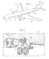
- the pictorial view shows an aircraft, generally 50, of conventional design.
- the aircraft 50 is provided with a fuselage, generally 52, wings 54, fixedly mounted on the opposite sides of the fuselage 52, a nose section 56 and a tail section, generally 58.
- a fuselage generally 52
- wings 54 fixedly mounted on the opposite sides of the fuselage 52
- a nose section 56 and a tail section, generally 58.
- the passenger/exit door 60 and multiple emergency exit doors 62 are provided along the length of the fuselage 52.
- FIGS. 2 and 3 there is shown the underside 64 of the fuselage 52.
- FIG. 2 shows a landing gear, generally 66, in the lowered position and also shows a pair of landing gear doors 68 hingedly secured to the underside 64 of the fuselage 52 by hinge mechanisms (not shown) of conventional design.
- FIG. 3 there is a showing of the underside 64 of the fuselage 52 wherein the landing gear doors 68 are in the closed position and the landing gear 66 is in a retracted position in the aircraft 50.
- the sensor 100 is schematically shown as having a frame, generally 102.
- the frame 102 includes an outer cylindrical wall 104 which provides an enclosed space for the sensor components contained therein.
- the outer wall 104 is enclosed by an upper wall 106 and a lower wall 108.
- the frame 102 further includes an upper platform 110 that is supported by the outer wall 104.
- the upper platform 110 is spaced downwardly from the upper wall 106.
- a lower platform 112 is spaced downwardly from the upper platform 110 and is supported on its outer edge by the outer wall 104.
- a plunger assembly generally 114 is mounted in an aperture provided in the upper wall 106 of the frame 102.
- the plunger assembly 114 includes an upwardly projecting portion 116 which projects above the upper wall 106 of the outer frame 102.
- the plunger assembly 114 includes a unitary shoulder 118.
- the plunger assembly 114 is generally cylindrical in shape.
- the plunger assembly 114 also includes an interior lower portion 120.
- a threaded boss 122 is schematically shown and is provided with a jam nut to secure the fiber optic position sensor 100 to the aircraft 50 operatively near to a movable component of the aircraft 50 such as the fuselage doors 60 and 62, the landing gear doors 68 or the landing gear 64.
- a seal 124 is provided in the boss 122 for slideably and sealably guiding the cylindrical plunger 116.
- the upper platform 110 and lower platform 112 of the frame 102 each includes seals 124 to provide similar guiding support for the reciprocal movement of the plunger assembly 114 within the frame 102.
- the frame 102 provides an enclosure for the interior components of the sensor 100 to be described.
- the seals 124 cooperate with the enclosed frame to avoid any exterior contamination from entering the enclosed frame 102.
- a biasing spring 126 bears against a unitary shoulder 118 of the plunger assembly 114 at its upper end. At the lower end, the spring 126 rests against the upper surface of the upper platform 110. The biasing spring 126 acts to bias the plunger assembly 114 upwardly to position the upwardly projecting portion 116 above the threaded boss assembly 122. In the position shown in FIG. 4 , the plunger assembly 114 is in a rest position. As will be described hereinafter, the plunger assembly 114 has an activated position when the plunger assembly 114 is moved downwardly such as by a component of a door 60, such as doors 60, 62 and 68.
- One flat side 130 of the unitary shoulder 118 of the plunger assembly 114 is in close slideable proximity to a flat upright wall 128 that is fixed to the upper wall 106 and to the upper platform 110. With the flat side 130 of the shoulder 118 of the plunger assembly 114 bearing against the flat wall 128, during reciprocal movement of the plunger assembly 114, rotation of the plunger assembly 114 is prevented. It is to be understood that other types of guides may be provided for preventing rotation of the plunger assembly 114.
- the lower end 132 of the plunger assembly 114 fixedly carries a planar reflector 134 for reflecting a light beam as will be hereinafter described in further detail. Since the plunger assembly 114 is prevented from rotating, the flat reflector 134 faces laterally directly outwardly at 90 degrees to an imaginary central axis 136 of the plunger assembly 114 as shown in dotted view that extends downwardly and beyond the lower end 132 of the plunger assembly 114.
- the lower wall 108 of the frame 102 has a fiber optic assembly 138 securely mounted in an aperture provided therein.
- the fiber optic assembly 138 has a multi-mode optical fiber 140 secured therein.
- a collimating lens 142 is secured at the upper exit end of the multi-mode optical fiber 140 and is rigidly secured within the fiber optic assembly 138.
- the lens 142 is securely bonded within the fiber optic assembly 138 and is set securely in position against the upper surface of the multi-mode optical fiber 140.
- a prism 144 is rigidly secured to the upper surface of the fiber optic assembly 138.
- the collimating lens 142 focuses or narrows a light beam as represented by lines 146.
- the light beam 146 meets the hypotenuse 148 of the prism 144 and the prism 144 redirects the light beam at 90 degrees towards a light absorber 150.
- the light absorber 150 is secured to the lower wall 108 of the frame and is fixed in position against a side of the fiber optic assembly 138.
- the light absorber 150 is made of a known material, for example, a non-reflective material such as black foam.
- the light absorber 150 absorbs the light beam 146 so there is the absence of reverse movement of the light beam 146 in the optical fiber 140.
- a threaded boss 152 is secured to the lower surface of the fiber optic assembly 138.
- the multi-mode optical fiber 140 is a section that extends from the lower surface of the lens 142 to the lower surface of the threaded boss 152. From the above description it is seen that the optical fiber assembly 138, supports the optical fiber 140, the lens 142, and the prism 144.
- a connector 154 has a multi-mode optical fiber extension member 155 secured therein.
- the connector 154 is secured to the threaded boss 152.
- the optical fiber member 155 has an end thereof securely pressed against the lower end of the section of the optical fiber 140 positioned in the optical fiber assembly 138.
- the optical fiber extension member 155 is connected to an operating member to be hereinafter described.
- the optical fiber extension member 155 is the same type of multi-mode optical fiber as the multi-mode optical fiber 140. In actual operation, the optical fiber 140 and the optical fiber extension member 155 function in a unitary and cooperative manner.
- FIG. 7 there is a provided a schematic drawing of the fiber optic position sensor 100 in which the plunger assembly 114 is in the rest position.
- FIG. 7 schematically shows a door 160 in the open position and with the sensor 100 in the rest position, that is, when the plunger assembly 114 is not depressed.
- the door 160 may be any type of door used on a wide variety of components and would include land based structures and vehicles, sea based ships at sea, and aircraft of all kinds, all of which have one or more doors that move between open and closed positions.
- the door 160 is intended to reference landing gear doors 68 as shown in FIG. 2 .
- the fiber optic position sensor 100 is in the rest position and the door 160 is in the open position.
- the fiber optic position sensor 100 is connected by an optical fiber member 155 to an optical transceiver 162.
- the optical transceiver 162 is connected by another optical fiber member 155 to a system controller, generally 164.
- the system controller 164 is connected by an electrical wire 165, such as copper wire, that is split into two electrical wires 165 with one wire 165 connected to a door open light 166 and with the other electrical wire 165 connected to a door closed light 168.
- the plunger assembly 114 is at rest.
- a light beam 146 passes through the multi-mode optical fiber 140, and then is passed through the collimating lens 142.
- the collimating lens 142 focuses the light beam 146 as it passes through the prism 144 and is reflected by the hypotenuse 148 of the prism 144 in a transverse direction through an open space.
- the light beam 146 is received by the light absorber 150.
- the fiber optic position sensor 100 indicates the absence of light since there is no reverse movement of the light beam 146 in the multi-mode optical fiber 140. In this way, an absence of the reverse movement of the light beam 146 in the optical fibers 140 and 155 is transmitted to the optical transceiver 162.
- the indicator light 166 indicates then that the door 160 is in the open position.
- the plunger assembly 114 when the door 160 is moved to the closed position, the plunger assembly 114 is depressed when the door 160 reaches the fully closed position.
- the lower end 132 of the plunger assembly 114 carries the reflector 134 which is positioned in the open space between the light absorber 150 and the prism 144.
- the light beam 148 intercepts the imaginary center line 136 of the plunger assembly 114.
- the plunger assembly 114 positions the reflector 134, carried at the lower end 132 of the plunger assembly 114, between the prism 144 and the light absorber 150. At this time, the reflector 134 reflects the light beam 148 back to the prism 144 which directs the light beam in a reverse direction through the optical fiber 140 and the optical fiber member 155.
- the reverse direction of the light beam 146 sends a presence of light signal back through the optical fiber 140 to the optical transceiver 162.
- This reverse direction of the light beam 146 signals the optical transceiver 162 that the door 160 is in the closed position.
- the optical transceiver 162 sends a signal to the system controller 164, through the optical fiber member 155, which in turn sends a signal through the electrical wire 165 to the indicator light 168 to indicate that the door 160 is in the door closed position.
- a fiber optic position sensor generally 250, of the normally closed type.
- the fiber optic position sensor 250 as shown in FIG. 5 is quite similar in both structure and method of use to the fiber optic position sensor 100.
- Both the normally open position sensor 100 and the normally closed position sensor 250 operate in a system that detects the presence of a light beam moving in a reverse direction in an optical fiber and alternatively that detects the absence of a light beam moving in a reverse direction in an optical fiber. The presence or absence of such a light beam provides a signal to an indicator light that, for example, a door on an aircraft is open or closed.
- the normally closed sensor 250 of FIG. 5 includes an outer frame, generally 252.
- the outer frame 252 includes an outer wall 254, preferably cylindrical, that provides an enclosed space for isolating the sensor components, to be described, from exterior contamination.
- the outer wall 254 of the sensor 250 has an upper wall 256 and a lower wall 258 connected thereto.
- An upper platform 260 is spaced below the upper wall 256 and a lower platform 262 is spaced below the upper platform 260. Both platforms 260 and 262 are secured at their outer edges to the outer wall 254.
- the normally closed sensor 250 has a plunger assembly, generally 264, mounted in an aperture provided in the upper wall 256 of the outer frame 252.
- the plunger assembly 264 includes an upwardly projecting portion 266 which projects above the upper wall 256.
- the plunger assembly 264 further includes a unitary shoulder 268.
- the plunger assembly 264 is generally cylindrical in shape.
- the plunger assembly 264 includes a lower portion 270.
- a threaded boss 272 is schematically shown and is secured to the upper wall 256 of the frame 252.
- the threaded boss 272 is provided with a jam nut for securing the sensor 250 to the aircraft 50 in operative proximity to a door of the aircraft 50 for signaling that the door is in an open or a closed position.
- a seal 274 is provided in the boss 272 for providing a guide support and seal for the reciprocal movement of the plunger assembly 264 within the frame 252 to seal the enclosed frame 252 from any potential exterior contamination.
- a biasing spring 276 bears against the unitary shoulder 268 of the plunger assembly 264 at its upper end 266 and at its lower end, the biasing spring 276 rests against the upper surface of the upper platform 260.
- the biasing spring 276 acts to bias the plunger assembly 264 upwardly to position the upwardly projecting portion 266 above the threaded boss 272. As shown in FIG. 5 , the plunger assembly 264 is shown in a rest position.
- the plunger assembly 264 has an activated position when the plunger assembly 264 is pushed downwardly as will be hereinafter described.
- the lower end of the plunger assembly 264 carries a preferably cylindrical light absorber 278 for absorbing a light beam in a manner to be hereinafter described.
- the plunger assembly 264 includes an imaginary central axis 280 shown in dotted view that extends downwardly and beyond the lower end of the plunger assembly 264.
- the lower wall 258 of the frame 252 has a fiber optic assembly 282 securely mounted in an aperture provided in the lower wall 258.
- the fiber optic assembly 282 has a multi-mode optical fiber 284 secured therein.
- a collimating lens 286 focuses or narrows a light beam as represented by lines 288.
- the collimating lens 286 is rigidly secured within the fiber optic assembly 282 and rests on top of the multi-mode optical fiber 284.
- the rapidly moving light beam 288 in the multi-mode optical fiber 284 passes through the lens 286 and the light beam 288 subsequently meets the hypotenuse 289 of a prism 290 which is in a fixed position on the fiber optic assembly 282 immediately above the collimating lens 286.
- the prism 290 redirects the light beam at a 90 degree angle.
- a light beam reflector 292 is mounted on the fiber optic assembly 282 and is spaced laterally away from the upright wall of the prism 290.
- the reflector 292 reflects the light beam 288 in a reverse direction back to the prism 290.
- the prism 290 reflects the light beam 288 in the reverse direction back through the collimating lens 286 and back through the multi-mode optical fiber 284.
- the multi-mode optical fiber 284 comprises a section that extends from the lower surface of the lens 286 to the lower surface of the threaded boss 285.
- the optical fiber assembly 282 supports the optical fiber 284, the lens 286, the prism 290 and the reflector 292.
- the light beam interrupter or light absorber 278 is made of a known structure of a non-reflective material, such as black foam material.
- the light absorber 278 absorbs the light beam 288 before the light beam 288 can be reflected in a reverse direction by the reflector 292.
- the plunger assembly 264 and light absorber 278 are raised to the rest position, the light beam 288 is reflected by the reflector 292 back to the prism 290 and then the prism 290 directs the light beam downwardly from the hypotenuse 291 of the prism 290 in a reverse direction through the section of multi-mode optical fiber 284 in the fiber optic assembly 282.
- a connector 294 has a multi-mode optical fiber extension member 296 secured therein.
- the connector 294 is secured to the threaded boss 285.
- the optical fiber extension member 296 has one end thereof secured against the lower end of the optical fiber 284 which is secured in the optical fiber assembly 282.
- the optical fiber member 296 is connected to an operating member to be hereinafter described.
- the optical fiber member 296 is the same type of multi-mode optical fiber as the multi-mode optical fiber 284. In actual operation, the optical fiber 284 and the optical fiber member function in a unitary and cooperative manner.
- a door 160 is schematically shown and represents any of the doors 60, 62, and 68 on the aircraft 50.
- the door 160 is in the open position and the fiber optic position sensor 250 is in the rest position.
- the fiber optic position sensor 250 is connected to the optical transceiver 162 by an optical fiber extension member 296 and the optical transceiver 162 is connected to the system controller 164 by an optical fiber extension member 296.
- the system controller 164 is connected to the door open indicator light 166 and the door closed indicator light 168 by electrical wires 286, such as copper wires.
- the door 160 is in the open position and the fiber optic position sensor 250 is shown in the rest position.
- the sensor 250 is in the rest position and the plunger assembly 264 is in the rest position.
- the biasing spring 276 raises the plunger assembly 264 to the rest position.
- the light beam absorber 278 is cylindrical in shape and rests above the space between the reflector 292 and the prism 290.
- the optical transceiver 162 sends a light beam 288 through the optical fiber 284 and the collimating lens 286 focuses or narrows the light beam 288 to project against the hypotenuse 289 of the prism 290.
- the light beam 288 is reflected at approximately a 90 degree angle directly towards the reflector 292.
- the reflector 292 reflects the light beam 288 back to the prism 290 and the prism 290 then reflects the light beam 288 in a reverse direction back through the collimating lens 286 and through the multi-mode optical fiber 284 and the optical fiber member 296.
- the reverse direction of the light beam 288 sends a signal to the optical transceiver 162 that a reverse light beam 288 is present.
- the optical transceiver 162 transmits the signal back to the system controller 164 through the optical fiber extension member 296.
- the system controller 164 then sends a signal through the electrical wires 286 to the door open light indicator 168 signaling that the door 160 is open.
- the door 160 is shown in the closed position.
- the plunger assembly 264 has been depressed in response to the closed door 160 and is moved downwardly within the frame 252.
- the light beam absorber 278, which is preferably cylindrical in shape, is moved into the space between the reflector 292 and the prism 290.
- the light absorber 278 absorbs the light beam 288 and prevents the reverse direction of the light beam in the optical fiber 284 since the light beam 288 has been intercepted by the light absorber 278, the plunger assembly 264 having moved the light absorber 278 into the active position. In this way, there is no reverse movement of the light beam 288 from the light beam absorber 278.
- a signal is received by the optical transceiver 162 that there is an absence of a reverse movement of a light beam 288 in the optical fiber 284.
- This information is transmitted from the transceiver 162 to the system controller 164 through an optical fiber extension member 296.
- the system controller 164 sends a signal through the electrical wires 286 to the door closed indicator light 168 advising that the door 160 is in the closed position.
Landscapes
- Physics & Mathematics (AREA)
- General Physics & Mathematics (AREA)
- Optics & Photonics (AREA)
- Length Measuring Devices By Optical Means (AREA)
- Geophysics And Detection Of Objects (AREA)
Abstract
Description
- Certain embodiments of the disclosure relate generally to fiber optic position sensors for use in the control of mechanical systems and methods for using the sensors. More specifically, certain embodiments of the disclosure relate to fiber optic position sensors that are particularly useful for controlling mechanical systems in aircraft such as for indicating the open and closed positions of landing gear and of various aircraft door operating systems.
- Fiber optic technology is a relatively new form of technology particularly used in communication systems, such as for the transmission of telephone signals, internet communication systems and cable television signals. Simply stated, fiber optic technology comprises a system of transmitting information by using pulses of light through an optical fiber assembly.
- One principal advantage of fiber optic communication systems is that there is virtually non-existent electromagnetic interference (EMI) when using optical fibers in an operating system. The lack of EMI issues is a very significant benefit as it results in a high level of reliability. Another distinct advantage of fiber optic usage to the aircraft industry is that fiber optic systems are much lighter in weight than copper and aluminum wiring used in aircraft. The reduction in weight of wiring used in aircraft is a significant benefit since any reduction in weight of an aircraft improves fuel efficiency levels.
- Position sensors are commonly used in aircraft for a variety of purposes. One broad area of use of position sensors involves indicator lights indicating whether any of the various doors used in aircraft are in the open or closed positions. Position sensors used in connection with commercial aircraft components include, but are not limited to passenger entry/exit doors, emergency doors, cockpit security doors, landing gear doors, and landing gear assemblies themselves; in military aircraft, position sensors are useful in indicating whether bomb bay doors are open or closed.
- Further limitations and disadvantages of conventional and traditional approaches will become apparent to one of skill in the art, through comparison of such systems with the present disclosure as set forth in the remainder of the present application with reference to the drawings.
- In one aspect of the disclosure, a position sensor is provided for detecting both an absence and a presence of a light beam moving in an optical fiber and detecting first and second component positions of a structure. The position sensor includes a frame and a plunger linearly and reciprocally mounted along an axis on the frame. The plunger has first and second plunger positions and is coordinated with the first and second component positions respectively. The optical fiber is mounted on the frame and is capable of having the light beam move in a first direction in the optical fiber at all times and is capable of having the light beam move in a reverse direction in the optical fiber member when the component position changes between the first and second component positions and when the plunger position changes between the first and second plunger positions in coordination with the first and second component positions. A detector indicates the absence of the reverse direction of the light beam moving in the optical fiber and indicates the presence of the light beam moving in the first direction in the optical fiber.
- In another aspect of the disclosure, a position sensor is provided for detecting the presence of a light beam and the absence of a light beam moving in an optical fiber for providing a position signal of a component of an operating system of a structure. The position sensor includes a frame with a plunger linearly and reciprocally mounted along an axis on the frame between first and second positions. The optical fiber is mounted on the frame and is capable of having the light beam move in a first direction and in a reverse direction in the optical fiber. A prism is mounted in the frame for redirecting the light beam moving in a first direction in the optical fiber to at least the axis of the plunger and for redirecting the light beam moving in a reverse direction from the axis to the optical fiber. A reflector is mounted in the frame and has both an inoperative position and an operative position. The reflector, when in the operative position, reflects the light beam from the first direction into the reverse direction to the prism and the prism directs the light beam in the reverse direction into the optical fiber while providing a position signal of the presence of the reverse direction of the light beam in the optical fiber. A light beam absorber is mounted in the frame and has an inoperative condition and an operative condition. When the light beam absorber is in the operative condition, the light beam is absorbed and prevents the reverse direction of the light beam in the optical fiber. The reflector is in the inoperative condition when the light beam is in the operative condition, while providing a position signal of the absence of the reverse direction of the light beam in the optical fiber.
- In a still further aspect of the disclosure, a method is provided for detecting both the absence and the presence of a light beam moving in an optical fiber for determining the position of a component. The optical fiber that is provided has the capability of having a light beam move in a first direction in the optical fiber and is capable of having the light beam move in a reverse direction in the optical fiber when the position of the component has changed. The absence of the light beam is detected when the light beam is not moving in the reverse direction in the optical fiber.
- The features, functions, and advantages that have been discussed can be achieved independently in various embodiments or may be combined in yet other embodiments, further details of which can be seen with reference to the following description and drawings.
-
-
FIG. 1 is pictorial view of an aircraft having multiple doors thereon wherein fiber optic position sensors can be utilized for detecting open and closed positions of the doors; -
FIG. 2 is pictorial view of the underside of an aircraft showing the lowered position of a landing gear and the open position of landing gear doors; wherein fiber optic position sensors may be utilized for indicating such positions; -
FIG. 3 is a view similar toFIG. 2 showing the landing gear doors in the closed position; -
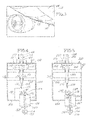
FIG. 4 is a view of a fiber optic position sensor of a normally open type of sensor; -
FIG. 5 is a view of a fiber optic position sensor of a normally closed type of sensor; -
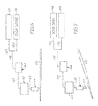
FIG. 6 is a schematic view showing a door of an aircraft in a closed position operatively connected to a fiber optic position sensor of a normally open type interconnected to a transceiver and the transceiver is connected to a controller which is connected to indicators, such as lights, indicating that a particular door is in the closed position, wherein fiber optic members interconnect the position sensor, the transceiver and the controller; -
FIG. 7 is a view similar toFIG. 6 except showing the particular door of the aircraft in the open position; -
FIG. 8 is a view similar toFIG. 6 except the fiber optic position sensor is of the normally closed type; and -
FIG. 9 is a view similar toFIG. 7 except the fiber optic position sensor is of the normally closed type. - By combining the benefits of fiber optics with the range of possible uses for position sensors in aircraft, it would be highly desirable to provide a fiber optic position sensor in connection with systems related to indicators for open and closed positions of various moveable parts, such as doors and landing gear on an aircraft. Such moveable parts have operating systems. The combining of fiber optics with position sensors in aircraft would provide light weight communications with high reliability and minimal or no electromagnetic interference (EMI) with the position sensors. The operating systems of the moveable parts, as will be described herein, are communicatively coupled to the position sensors.
- The following description and accompanying drawings provide details of a fiber optic position sensor for detecting the presence or absence of a light beam in an operating system. The description, as follows, is not to be considered in a limiting sense, but it is provided for the purpose of illustrating the general principle of the claims relating to the described fiber optic position sensor and method for its use. The scope of the disclosure will be defined by the claims following the detailed description.
- The description of the fiber optic position sensor is, for purposes of illustration, primarily directed to use with aircraft of the type that use a wide range of components, such as doors, that utilize indicator lights for indicating open and closed positions on any or all of the doors on the aircraft. The fiber optic position sensor being described herein is not limited for use with aircraft, but is intended to include a wide range of structures including fixed land based structures and vehicles, ships at sea and any type of aircraft or aerospace vehicles. Further, the components used in connection with the fiber optic sensors extend over a wide range.
- Referring to
FIG. 1 , the pictorial view shows an aircraft, generally 50, of conventional design. Theaircraft 50 is provided with a fuselage, generally 52,wings 54, fixedly mounted on the opposite sides of thefuselage 52, anose section 56 and a tail section, generally 58. Of particular interest relative to the present disclosure are the passenger/exit door 60 and multipleemergency exit doors 62, all of which are provided along the length of thefuselage 52. - Referring to
FIGS. 2 and3 , there is shown theunderside 64 of thefuselage 52.FIG. 2 shows a landing gear, generally 66, in the lowered position and also shows a pair oflanding gear doors 68 hingedly secured to theunderside 64 of thefuselage 52 by hinge mechanisms (not shown) of conventional design. Referring toFIG. 3 , there is a showing of theunderside 64 of thefuselage 52 wherein thelanding gear doors 68 are in the closed position and thelanding gear 66 is in a retracted position in theaircraft 50. - Referring to
FIG. 4 , there is shown a fiber optic position sensor, generally 100, of the normally open type which is one type of fiber optic position sensor to be described herein. Thesensor 100 is schematically shown as having a frame, generally 102. Theframe 102 includes an outercylindrical wall 104 which provides an enclosed space for the sensor components contained therein. Theouter wall 104 is enclosed by anupper wall 106 and alower wall 108. Theframe 102 further includes an upper platform 110 that is supported by theouter wall 104. The upper platform 110 is spaced downwardly from theupper wall 106. Alower platform 112 is spaced downwardly from the upper platform 110 and is supported on its outer edge by theouter wall 104. - A plunger assembly, generally 114 is mounted in an aperture provided in the
upper wall 106 of theframe 102. Theplunger assembly 114 includes an upwardly projecting portion 116 which projects above theupper wall 106 of theouter frame 102. Theplunger assembly 114 includes aunitary shoulder 118. Theplunger assembly 114 is generally cylindrical in shape. Theplunger assembly 114 also includes an interior lower portion 120. A threaded boss 122 is schematically shown and is provided with a jam nut to secure the fiberoptic position sensor 100 to theaircraft 50 operatively near to a movable component of theaircraft 50 such as thefuselage doors landing gear doors 68 or thelanding gear 64. Aseal 124 is provided in the boss 122 for slideably and sealably guiding the cylindrical plunger 116. In a similar manner, the upper platform 110 andlower platform 112 of theframe 102 each includes seals 124 to provide similar guiding support for the reciprocal movement of theplunger assembly 114 within theframe 102. Theframe 102 provides an enclosure for the interior components of thesensor 100 to be described. Theseals 124 cooperate with the enclosed frame to avoid any exterior contamination from entering theenclosed frame 102. - A biasing
spring 126 bears against aunitary shoulder 118 of theplunger assembly 114 at its upper end. At the lower end, thespring 126 rests against the upper surface of the upper platform 110. The biasingspring 126 acts to bias theplunger assembly 114 upwardly to position the upwardly projecting portion 116 above the threaded boss assembly 122. In the position shown inFIG. 4 , theplunger assembly 114 is in a rest position. As will be described hereinafter, theplunger assembly 114 has an activated position when theplunger assembly 114 is moved downwardly such as by a component of adoor 60, such asdoors unitary shoulder 118 of theplunger assembly 114 is in close slideable proximity to a flatupright wall 128 that is fixed to theupper wall 106 and to the upper platform 110. With the flat side 130 of theshoulder 118 of theplunger assembly 114 bearing against theflat wall 128, during reciprocal movement of theplunger assembly 114, rotation of theplunger assembly 114 is prevented. It is to be understood that other types of guides may be provided for preventing rotation of theplunger assembly 114. - The
lower end 132 of theplunger assembly 114 fixedly carries aplanar reflector 134 for reflecting a light beam as will be hereinafter described in further detail. Since theplunger assembly 114 is prevented from rotating, theflat reflector 134 faces laterally directly outwardly at 90 degrees to an imaginarycentral axis 136 of theplunger assembly 114 as shown in dotted view that extends downwardly and beyond thelower end 132 of theplunger assembly 114. - The
lower wall 108 of theframe 102 has afiber optic assembly 138 securely mounted in an aperture provided therein. Thefiber optic assembly 138 has a multi-modeoptical fiber 140 secured therein. A collimating lens 142 is secured at the upper exit end of the multi-modeoptical fiber 140 and is rigidly secured within thefiber optic assembly 138. The lens 142 is securely bonded within thefiber optic assembly 138 and is set securely in position against the upper surface of the multi-modeoptical fiber 140. Immediately above the collimating lens 142, aprism 144 is rigidly secured to the upper surface of thefiber optic assembly 138. The collimating lens 142 focuses or narrows a light beam as represented bylines 146. Thelight beam 146 meets thehypotenuse 148 of theprism 144 and theprism 144 redirects the light beam at 90 degrees towards alight absorber 150. Thelight absorber 150 is secured to thelower wall 108 of the frame and is fixed in position against a side of thefiber optic assembly 138. Thelight absorber 150 is made of a known material, for example, a non-reflective material such as black foam. Thelight absorber 150 absorbs thelight beam 146 so there is the absence of reverse movement of thelight beam 146 in theoptical fiber 140. A threadedboss 152 is secured to the lower surface of thefiber optic assembly 138. The multi-modeoptical fiber 140 is a section that extends from the lower surface of the lens 142 to the lower surface of the threadedboss 152. From the above description it is seen that theoptical fiber assembly 138, supports theoptical fiber 140, the lens 142, and theprism 144. - Referring to the lower area of
Fig 4 , aconnector 154 has a multi-mode opticalfiber extension member 155 secured therein. Theconnector 154 is secured to the threadedboss 152. Theoptical fiber member 155 has an end thereof securely pressed against the lower end of the section of theoptical fiber 140 positioned in theoptical fiber assembly 138. The opticalfiber extension member 155 is connected to an operating member to be hereinafter described. The opticalfiber extension member 155 is the same type of multi-mode optical fiber as the multi-modeoptical fiber 140. In actual operation, theoptical fiber 140 and the opticalfiber extension member 155 function in a unitary and cooperative manner. - Referring to
FIG. 7 , there is a provided a schematic drawing of the fiberoptic position sensor 100 in which theplunger assembly 114 is in the rest position.FIG. 7 schematically shows adoor 160 in the open position and with thesensor 100 in the rest position, that is, when theplunger assembly 114 is not depressed. Thedoor 160 may be any type of door used on a wide variety of components and would include land based structures and vehicles, sea based ships at sea, and aircraft of all kinds, all of which have one or more doors that move between open and closed positions. For purpose of illustration, thedoor 160 is intended to referencelanding gear doors 68 as shown inFIG. 2 . - As shown in
FIG. 7 , the fiberoptic position sensor 100 is in the rest position and thedoor 160 is in the open position. The fiberoptic position sensor 100 is connected by anoptical fiber member 155 to anoptical transceiver 162. Theoptical transceiver 162 is connected by anotheroptical fiber member 155 to a system controller, generally 164. Thesystem controller 164 is connected by anelectrical wire 165, such as copper wire, that is split into twoelectrical wires 165 with onewire 165 connected to a dooropen light 166 and with the otherelectrical wire 165 connected to a doorclosed light 168. - Referring to
FIG. 4 , in this position, theplunger assembly 114 is at rest. Alight beam 146 passes through the multi-modeoptical fiber 140, and then is passed through the collimating lens 142. The collimating lens 142 focuses thelight beam 146 as it passes through theprism 144 and is reflected by thehypotenuse 148 of theprism 144 in a transverse direction through an open space. Thelight beam 146 is received by thelight absorber 150. At this time, the fiberoptic position sensor 100 indicates the absence of light since there is no reverse movement of thelight beam 146 in the multi-modeoptical fiber 140. In this way, an absence of the reverse movement of thelight beam 146 in theoptical fibers optical transceiver 162. Theindicator light 166 indicates then that thedoor 160 is in the open position. - Referring to
FIG. 6 , when thedoor 160 is moved to the closed position, theplunger assembly 114 is depressed when thedoor 160 reaches the fully closed position. Thelower end 132 of theplunger assembly 114 carries thereflector 134 which is positioned in the open space between thelight absorber 150 and theprism 144. Thelight beam 148 intercepts theimaginary center line 136 of theplunger assembly 114. Theplunger assembly 114 positions thereflector 134, carried at thelower end 132 of theplunger assembly 114, between theprism 144 and thelight absorber 150. At this time, thereflector 134 reflects thelight beam 148 back to theprism 144 which directs the light beam in a reverse direction through theoptical fiber 140 and theoptical fiber member 155. The reverse direction of thelight beam 146 sends a presence of light signal back through theoptical fiber 140 to theoptical transceiver 162. This reverse direction of thelight beam 146 signals theoptical transceiver 162 that thedoor 160 is in the closed position. Theoptical transceiver 162 sends a signal to thesystem controller 164, through theoptical fiber member 155, which in turn sends a signal through theelectrical wire 165 to the indicator light 168 to indicate that thedoor 160 is in the door closed position. - Referring to
FIG. 5 , there is shown a fiber optic position sensor, generally 250, of the normally closed type. The fiberoptic position sensor 250 as shown inFIG. 5 is quite similar in both structure and method of use to the fiberoptic position sensor 100. Both the normallyopen position sensor 100 and the normally closedposition sensor 250 operate in a system that detects the presence of a light beam moving in a reverse direction in an optical fiber and alternatively that detects the absence of a light beam moving in a reverse direction in an optical fiber. The presence or absence of such a light beam provides a signal to an indicator light that, for example, a door on an aircraft is open or closed. - The normally closed
sensor 250 ofFIG. 5 includes an outer frame, generally 252. Theouter frame 252 includes anouter wall 254, preferably cylindrical, that provides an enclosed space for isolating the sensor components, to be described, from exterior contamination. Like the normallyopen sensor 100, theouter wall 254 of thesensor 250 has anupper wall 256 and alower wall 258 connected thereto. Anupper platform 260 is spaced below theupper wall 256 and alower platform 262 is spaced below theupper platform 260. Bothplatforms outer wall 254. - The normally closed
sensor 250 has a plunger assembly, generally 264, mounted in an aperture provided in theupper wall 256 of theouter frame 252. Theplunger assembly 264 includes an upwardly projectingportion 266 which projects above theupper wall 256. Theplunger assembly 264 further includes aunitary shoulder 268. Theplunger assembly 264 is generally cylindrical in shape. Theplunger assembly 264 includes alower portion 270. A threadedboss 272 is schematically shown and is secured to theupper wall 256 of theframe 252. The threadedboss 272 is provided with a jam nut for securing thesensor 250 to theaircraft 50 in operative proximity to a door of theaircraft 50 for signaling that the door is in an open or a closed position. A seal 274 is provided in theboss 272 for providing a guide support and seal for the reciprocal movement of theplunger assembly 264 within theframe 252 to seal theenclosed frame 252 from any potential exterior contamination. - A biasing spring 276 bears against the
unitary shoulder 268 of theplunger assembly 264 at itsupper end 266 and at its lower end, the biasing spring 276 rests against the upper surface of theupper platform 260. The biasing spring 276 acts to bias theplunger assembly 264 upwardly to position the upwardly projectingportion 266 above the threadedboss 272. As shown inFIG. 5 , theplunger assembly 264 is shown in a rest position. Theplunger assembly 264 has an activated position when theplunger assembly 264 is pushed downwardly as will be hereinafter described. - The lower end of the
plunger assembly 264 carries a preferably cylindrical light absorber 278 for absorbing a light beam in a manner to be hereinafter described. Theplunger assembly 264 includes an imaginarycentral axis 280 shown in dotted view that extends downwardly and beyond the lower end of theplunger assembly 264. - The
lower wall 258 of theframe 252 has afiber optic assembly 282 securely mounted in an aperture provided in thelower wall 258. Thefiber optic assembly 282 has a multi-modeoptical fiber 284 secured therein. Acollimating lens 286 focuses or narrows a light beam as represented bylines 288. Thecollimating lens 286 is rigidly secured within thefiber optic assembly 282 and rests on top of the multi-modeoptical fiber 284. The rapidly movinglight beam 288 in the multi-modeoptical fiber 284 passes through thelens 286 and thelight beam 288 subsequently meets thehypotenuse 289 of aprism 290 which is in a fixed position on thefiber optic assembly 282 immediately above thecollimating lens 286. Theprism 290 redirects the light beam at a 90 degree angle. Alight beam reflector 292 is mounted on thefiber optic assembly 282 and is spaced laterally away from the upright wall of theprism 290. Thereflector 292 reflects thelight beam 288 in a reverse direction back to theprism 290. Theprism 290 reflects thelight beam 288 in the reverse direction back through thecollimating lens 286 and back through the multi-modeoptical fiber 284. The multi-modeoptical fiber 284 comprises a section that extends from the lower surface of thelens 286 to the lower surface of the threaded boss 285. Theoptical fiber assembly 282 supports theoptical fiber 284, thelens 286, theprism 290 and thereflector 292. - The light beam interrupter or light absorber 278 is made of a known structure of a non-reflective material, such as black foam material. When the light absorber 278 is moved downwardly, in a manner to be hereinafter described, the light absorber 278 absorbs the
light beam 288 before thelight beam 288 can be reflected in a reverse direction by thereflector 292. When theplunger assembly 264 and light absorber 278 are raised to the rest position, thelight beam 288 is reflected by thereflector 292 back to theprism 290 and then theprism 290 directs the light beam downwardly from the hypotenuse 291 of theprism 290 in a reverse direction through the section of multi-modeoptical fiber 284 in thefiber optic assembly 282. - Referring to the lower area of
FIG. 5 , aconnector 294 has a multi-mode opticalfiber extension member 296 secured therein. Theconnector 294 is secured to the threaded boss 285. The opticalfiber extension member 296 has one end thereof secured against the lower end of theoptical fiber 284 which is secured in theoptical fiber assembly 282. Theoptical fiber member 296 is connected to an operating member to be hereinafter described. Theoptical fiber member 296 is the same type of multi-mode optical fiber as the multi-modeoptical fiber 284. In actual operation, theoptical fiber 284 and the optical fiber member function in a unitary and cooperative manner. - The method of using the normally closed
sensor 250 will be described with reference toFIGS. 5 ,8 and 9 . - Referring to
FIG. 9 , adoor 160 is schematically shown and represents any of thedoors aircraft 50. Thedoor 160 is in the open position and the fiberoptic position sensor 250 is in the rest position. The fiberoptic position sensor 250 is connected to theoptical transceiver 162 by an opticalfiber extension member 296 and theoptical transceiver 162 is connected to thesystem controller 164 by an opticalfiber extension member 296. Thesystem controller 164 is connected to the door open indicator light 166 and the door closedindicator light 168 byelectrical wires 286, such as copper wires. - Referring to
FIG. 9 , thedoor 160 is in the open position and the fiberoptic position sensor 250 is shown in the rest position. Thesensor 250 is in the rest position and theplunger assembly 264 is in the rest position. The biasing spring 276 raises theplunger assembly 264 to the rest position. The light beam absorber 278 is cylindrical in shape and rests above the space between thereflector 292 and theprism 290. Theoptical transceiver 162 sends alight beam 288 through theoptical fiber 284 and thecollimating lens 286 focuses or narrows thelight beam 288 to project against thehypotenuse 289 of theprism 290. Thelight beam 288 is reflected at approximately a 90 degree angle directly towards thereflector 292. Thereflector 292 reflects thelight beam 288 back to theprism 290 and theprism 290 then reflects thelight beam 288 in a reverse direction back through thecollimating lens 286 and through the multi-modeoptical fiber 284 and theoptical fiber member 296. The reverse direction of thelight beam 288 sends a signal to theoptical transceiver 162 that a reverselight beam 288 is present. Theoptical transceiver 162 transmits the signal back to thesystem controller 164 through the opticalfiber extension member 296. Thesystem controller 164 then sends a signal through theelectrical wires 286 to the door openlight indicator 168 signaling that thedoor 160 is open. - Referring to
FIG. 8 , thedoor 160 is shown in the closed position. Theplunger assembly 264 has been depressed in response to theclosed door 160 and is moved downwardly within theframe 252. Referring toFIG. 5 , the light beam absorber 278, which is preferably cylindrical in shape, is moved into the space between thereflector 292 and theprism 290. The light absorber 278 absorbs thelight beam 288 and prevents the reverse direction of the light beam in theoptical fiber 284 since thelight beam 288 has been intercepted by the light absorber 278, theplunger assembly 264 having moved the light absorber 278 into the active position. In this way, there is no reverse movement of thelight beam 288 from the light beam absorber 278. Since thelight beam 288 has not moved in a reverse direction, a signal is received by theoptical transceiver 162 that there is an absence of a reverse movement of alight beam 288 in theoptical fiber 284. This information is transmitted from thetransceiver 162 to thesystem controller 164 through an opticalfiber extension member 296. Thesystem controller 164 sends a signal through theelectrical wires 286 to the door closed indicator light 168 advising that thedoor 160 is in the closed position. - Clause 1: A position sensor for detecting first and second component positions of a component of a structure, the position sensor comprising:
- a frame;
- a plunger linearly and reciprocally mounted along an axis on the frame, the plunger having first and second plunger positions and being in coordination with the first and second component positions respectively;
- an optical fiber being mounted on the frame and being capable of having a light beam move in the first direction therein at all times and being capable of having the light beam move in the reverse direction in the optical fiber member when the component position changes between the first and second component positions and when the plunger member position has changed between the first and second plunger member positions in coordination with the first and second component positions; and
- a detector for indicating the absence of the reverse direction of the light beam moving in the optical fiber and for indicating the presence of the light beam moving in the first direction in the optical fiber.
- Clause 2: The position sensor of Clause 1 wherein the structure is an aircraft and includes an operating system wherein the operating system is communicatively coupled to the position sensor.
- Clause 3: The position sensor of Clause 1 wherein the frame provides an enclosed space for enclosing the plunger member, and at least a portion of the optical fiber member.
- Clause 4: The position sensor of Clause 1 including a prism mounted in the frame for redirecting the light beam moving in the first direction in the optical fiber member to at least the axis of the plunger member and for redirecting the light beam moving in the reverse direction from the axis to the optical fiber member.
- Clause 5: A position sensor for providing a position signal of a component of an operating system of a structure, the position sensor comprising:
- a frame;
- a plunger reciprocally mounted along an axis on the frame between first and second positions;
- an optical fiber mounted on the frame and being capable of having a light beam move in a first direction and in a reverse direction in the optical fiber member;
- a prism mounted in the frame for redirecting the light beam moving in the first direction in the optical fiber to at least the axis of the plunger member and for redirecting the light beam moving in the reverse direction from the axis to the optical fiber;
- a reflector mounted in the frame and having both an inoperative position and an operative position, the reflector, when in the operative position, reflecting the light beam from the first direction into the reverse direction to the prism, the prism directing the light beam in the reverse direction into the optical fiber, while providing the position signal of the component via the presence of the reverse direction of the light beam moving in the optical fiber; and
- a light beam absorber mounted in the frame having an inoperative condition and an operative condition, when the light beam absorber is in the operative condition absorbing the light beam while preventing the reverse direction of the light beam in the optical fiber, and the reflector being in the inoperative condition when the light beam absorber is in the operative condition, while providing the position signal of the absence of the reverse direction of the light beam in the optical fiber.
- Clause 6: The position sensor of Clause 5 wherein the structure is an aircraft, the operating system is a landing gear operating system operatively mounted within the aircraft, and the component is a landing gear having a lowered position and a raised position within the aircraft.
- Clause 7: The position sensor of Clause 5 wherein the plunger assembly includes a lower portion, the reflector member being mounted on the lower portion of the plunger assembly; and
the light beam absorber being fixedly mounted on the frame;
the reflector member being in an inoperative position when the plunger assembly is in the first position and being in the operative position when the plunger assembly is in the second position, and when the reflector member is in the operative position, the light beam is reflected back to the prism in the reverse direction and the reflector member prevents the light beam from reaching the light beam absorber. - Clause 8: The position sensor of Clause 5 wherein the reflector member is mounted in a fixed position within the frame and is within the operative position for reflecting the light beam from the first direction into the reverse direction.
- Clause 9: The position sensor of Clause 5 wherein the plunger member includes a lower portion, the light beam absorber is mounted on the lower portion of the plunger assembly, and when the light beam absorber is in the operative position, the light beam absorber prevents the reverse direction of the light beam in the optical fiber member, the light beam absorber having prevented the passage of the light beam to the reflector.
- Clause 10: The position sensor of Clause 5 including a collimating lens sandwiched between the optical fiber member and the prism, the collimating lens focusing the light beam passing from the optical fiber member to the prism.
- Clause 11: A method comprising detecting both an absence and a presence of a light beam moving in an optical fiber to determine the position of a component.
- Clause 12: The method of Clause 11 wherein the component is a door of an aircraft and the determined position is open or closed.
- Clause 13: The method of Clause 12 wherein the closed position is determined when the light beam is redirected from moving in a first direction in moving in a reverse direction in the optical fiber.
- Clause 14: The method of Clause 13 wherein the open position is determined when the light beam is moving in the first direction in the optical fiber.
- Clause 15: The method of Clause 11 including the steps of providing a position sensor;
providing a frame for the position sensor;
providing a plunger;
reciprocally mounting the plunger on the frame along a central axis. - Clause 16: The method of Clause 15 including the steps of mounting a reflector within the frame, wherein the reflector has an inactive position and an active position.
- Clause 17: The method of Clause 16 including the step of installing a light absorber within the frame.
- Clause 18: The method of Clause 17 including the step of installing an optical fiber on the frame, the optical fiber being capable of having a light beam move both in a first direction and in a reverse direction therein.
- Clause 19: The method of claim 18 of positioning a prism in alignment with the light beam moving in the optical fiber; and
directing the light beam with the prism towards and to the light absorber for absorbing the light beam by the light absorber when the plunger and the reflector are in the inactive positions. - Clause 20: The method of Clause 19 including the steps of:
- detecting the absence of a light beam moving in the reverse direction in the optical fiber when the plunger and the reflector are in the inactive positions;
- externally moving the plunger to the activated position while intercepting the light beam moving in the first direction by the reflector and preventing the light absorber from absorbing the light beam;
- reflecting the light beam into the reverse direction with the reflector to the prism and from the prism to the optical fiber; and
- detecting the presence of the light beam moving in the reverse direction in the optical fiber when the component has been moved to a selected position.
- While the disclosure has been described with reference to certain embodiments, it will be understood by those skilled in the art that various changes may be made and equivalents may be substituted without departing from the spirit and scope of the present disclosure. In addition, many modifications may be made to adapt a particular situation or material to the teachings of the present disclosure without departing from its scope. Therefore, it is intended that the present disclosure not be limited to the particular embodiments disclosed, but that the present disclosure will include all embodiments falling within the scope of the appended claims.
Claims (10)
- A position sensor for detecting first and second component positions of a component of a structure, the position sensor comprising:a frame;a plunger linearly and reciprocally mounted along an axis on the frame, the plunger having first and second plunger positions and being in coordination with the first and second component positions respectively;an optical fiber being mounted on the frame and being capable of having a light beam move in a first direction therein and being capable of having the light beam move in a reverse direction in the optical fiber when the component position changes between the first and second component positions and when the plunger position has changed between the first and second plunger positions in coordination with the first and second component positions; anda detector for indicating the absence of the reverse direction of the light beam moving in the optical fiber and for indicating the presence of the light beam moving in the first direction in the optical fiber.
- The position sensor of claim 1 wherein the structure is an aircraft and includes an operating system wherein the operating system is communicatively coupled to the position sensor.
- The position sensor of claims 1-2 wherein the frame provides an enclosed space for enclosing the plunger member, and at least a portion of the optical fiber member.
- The position sensor of claims 1-3 including a prism mounted in the frame for redirecting the light beam moving in the first direction in the optical fiber to at least the axis of the plunger and for redirecting the light beam moving in the reverse direction from the axis to the optical fiber member.
- An apparatus for providing a position signal of a component of an operating system of a structure, the apparatus comprising:a frame;a plunger reciprocally mounted along an axis on the frame between first and second positions;an optical fiber mounted on the frame and being capable of having a light beam move in a first direction and in a reverse direction in the optical fiber member;a prism mounted in the frame for redirecting the light beam moving in the first direction in the optical fiber to at least the axis of the plunger and for redirecting the light beam moving in the reverse direction from the axis to the optical fiber;a reflector mounted in the frame and having both an inoperative position and an operative position, the reflector, when in the operative position, reflecting the light beam from the first direction into the reverse direction to the prism, the prism directing the light beam in the reverse direction into the optical fiber, while providing the position signal of the component via the presence of the reverse direction of the light beam moving in the optical fiber; anda light beam absorber mounted in the frame having an inoperative condition and an operative condition, when the light beam absorber is in the operative condition absorbing the light beam while preventing the reverse direction of the light beam in the optical fiber, and the reflector being in the inoperative condition when the light beam absorber is in the operative condition, while providing the position signal of the absence of the reverse direction of the light beam in the optical fiber.
- The apparatus of claim 5 wherein the structure is an aircraft, the operating system is a landing gear operating system operatively mounted within the aircraft, and the component is a landing gear having a lowered position and a raised position within the aircraft.
- The apparatus of claims 5-6 wherein the plunger includes a lower portion, the reflector being mounted on the lower portion of the plunger assembly; and
the light beam absorber being fixedly mounted on the frame;
the reflector being in an inoperative position when the plunger is in the first position and being in the operative position when the plunger is in the second position, and when the reflector is in the operative position, the light beam is reflected back to the prism in the reverse direction and the reflector prevents the light beam from reaching the light beam absorber. - The apparatus of claim 7 wherein the reflector is mounted in a fixed position within the frame and is within the operative position for reflecting the light beam from the first direction into the reverse direction.
- The apparatus of claims 5-8 wherein the plunger includes a lower portion, the light beam absorber is mounted on the lower portion of the plunger assembly, and when the light beam absorber is in the operative condition, the light beam absorber prevents the reverse direction of the light beam in the optical fiber member, the light beam absorber having prevented the passage of the light beam to the reflector.
- The apparatus of claims 5-9 including a collimating lens sandwiched between the optical fiber and the prism, the collimating lens focusing the light beam passing from the optical fiber to the prism.
Applications Claiming Priority (1)
| Application Number | Priority Date | Filing Date | Title |
|---|---|---|---|
| US13/901,793 US10001367B2 (en) | 2013-05-24 | 2013-05-24 | Fiber optic position sensor and method for using |
Publications (3)
| Publication Number | Publication Date |
|---|---|
| EP2806251A2 true EP2806251A2 (en) | 2014-11-26 |
| EP2806251A3 EP2806251A3 (en) | 2015-03-18 |
| EP2806251B1 EP2806251B1 (en) | 2022-03-02 |
Family
ID=50721617
Family Applications (1)
| Application Number | Title | Priority Date | Filing Date |
|---|---|---|---|
| EP14168256.7A Active EP2806251B1 (en) | 2013-05-24 | 2014-05-14 | Fiber optic position sensor and method for using |
Country Status (2)
| Country | Link |
|---|---|
| US (1) | US10001367B2 (en) |
| EP (1) | EP2806251B1 (en) |
Cited By (2)
| Publication number | Priority date | Publication date | Assignee | Title |
|---|---|---|---|---|
| GB2541896A (en) * | 2015-09-01 | 2017-03-08 | Airbus Operations Ltd | Position sensing |
| FR3088422A1 (en) * | 2018-11-14 | 2020-05-15 | Ifotec | POSITION DETECTOR, DOOR OPENING DETECTION DEVICE AND RELATED METHOD |
Families Citing this family (5)
| Publication number | Priority date | Publication date | Assignee | Title |
|---|---|---|---|---|
| US10732023B2 (en) * | 2016-03-24 | 2020-08-04 | Sikorsky Aircraft Corporation | Measurement system for aircraft, aircraft having the same, and method of measuring weight for aircraft |
| US10746378B2 (en) | 2016-10-27 | 2020-08-18 | Textron Innovations, Inc. | Optical indicator of mechanical state |
| CN106564349A (en) * | 2016-10-31 | 2017-04-19 | 广东工业大学 | Triphibian unmanned aerial vehicle |
| US11493695B2 (en) | 2019-06-25 | 2022-11-08 | Thomas C. Stewart | Sustained continuity non-powered optomechanical position switch utilizing self-testing multiplexed optocontrolling transceiver in a fiber-optic circuit |
| IT202100001031A1 (en) * | 2021-01-21 | 2022-07-21 | Mecaer Aviation Group S P A | TAILGATE FOR VEHICLES EQUIPPED WITH AN IMPROVED SAFETY SYSTEM |
Citations (5)
| Publication number | Priority date | Publication date | Assignee | Title |
|---|---|---|---|---|
| GB2078943A (en) * | 1980-06-18 | 1982-01-13 | Westinghouse Electric Corp | Optical valve position sensor system |
| JPS59102112A (en) * | 1982-12-03 | 1984-06-13 | Tokyo Keiso Kk | Digital converter device for rotary angle |
| JPS60155920A (en) * | 1984-01-25 | 1985-08-16 | Toyo Denso Co Ltd | Apparatus for detecting rotary position |
| US4607160A (en) * | 1982-09-21 | 1986-08-19 | Omron Tateisi Electronics Co. | Non-contact switching device |
| JPH1090007A (en) * | 1996-09-11 | 1998-04-10 | Fuji Electric Co Ltd | Position detection sensor |
Family Cites Families (13)
| Publication number | Priority date | Publication date | Assignee | Title |
|---|---|---|---|---|
| US2987960A (en) * | 1958-02-17 | 1961-06-13 | Bausch & Lomb | Optical system for endoscopes and the like |
| US4315147A (en) * | 1980-02-15 | 1982-02-09 | Battelle Memorial Institute | Photoelectric switch with visible signal |
| US4631401A (en) | 1984-06-06 | 1986-12-23 | Dieterich Standard Corporation | Optic sensors |
| EP0506847B1 (en) * | 1989-12-18 | 1996-08-28 | E.I. Du Pont De Nemours And Company | Fiber optic switch having a spherical reflector |
| US5101463A (en) * | 1991-05-03 | 1992-03-31 | Minnesota Mining And Manufacturing Company | Push-pull optical fiber connector |
| US5216246A (en) * | 1992-02-03 | 1993-06-01 | Xerox Corporation | Optical safety shutoff for machine cover |
| GB2267762B (en) * | 1992-06-11 | 1996-01-03 | Keymed | Optical endoscope having a zoom lens |
| US5461683A (en) * | 1994-05-09 | 1995-10-24 | Harman; Murray R. | Apparatus and method for aligning optical fibers |
| TW505244U (en) | 2001-10-31 | 2002-10-01 | Hon Hai Prec Ind Co Ltd | Prism type optical switch |
| DE10335313B4 (en) | 2003-08-01 | 2015-01-22 | Thorsten Kern | Force sensor, force sensor unit, elongate device and method for detecting a force |
| US7262595B2 (en) * | 2005-07-27 | 2007-08-28 | Simmonds Precision Products, Inc. | Segmented core for an inductive proximity sensor |
| US7660494B2 (en) | 2007-08-13 | 2010-02-09 | The Boeing Company | Fiber optic fuel detection system |
| DE202009008971U1 (en) | 2009-06-30 | 2009-08-27 | Bürkert Werke GmbH & Co.KG | Optical sensor finger |
-
2013
- 2013-05-24 US US13/901,793 patent/US10001367B2/en not_active Expired - Fee Related
-
2014
- 2014-05-14 EP EP14168256.7A patent/EP2806251B1/en active Active
Patent Citations (5)
| Publication number | Priority date | Publication date | Assignee | Title |
|---|---|---|---|---|
| GB2078943A (en) * | 1980-06-18 | 1982-01-13 | Westinghouse Electric Corp | Optical valve position sensor system |
| US4607160A (en) * | 1982-09-21 | 1986-08-19 | Omron Tateisi Electronics Co. | Non-contact switching device |
| JPS59102112A (en) * | 1982-12-03 | 1984-06-13 | Tokyo Keiso Kk | Digital converter device for rotary angle |
| JPS60155920A (en) * | 1984-01-25 | 1985-08-16 | Toyo Denso Co Ltd | Apparatus for detecting rotary position |
| JPH1090007A (en) * | 1996-09-11 | 1998-04-10 | Fuji Electric Co Ltd | Position detection sensor |
Cited By (6)
| Publication number | Priority date | Publication date | Assignee | Title |
|---|---|---|---|---|
| GB2541896A (en) * | 2015-09-01 | 2017-03-08 | Airbus Operations Ltd | Position sensing |
| EP3139134A1 (en) * | 2015-09-01 | 2017-03-08 | Airbus Operations Limited | Position sensing |
| US10220956B2 (en) | 2015-09-01 | 2019-03-05 | Airbus Operations Limited | Position sensing |
| FR3088422A1 (en) * | 2018-11-14 | 2020-05-15 | Ifotec | POSITION DETECTOR, DOOR OPENING DETECTION DEVICE AND RELATED METHOD |
| WO2020099765A1 (en) * | 2018-11-14 | 2020-05-22 | Ifotec | Position detector, door opening detection device and associated method |
| US11860005B2 (en) | 2018-11-14 | 2024-01-02 | Ifotec | Position detector, door opening detection device and associated method |
Also Published As
| Publication number | Publication date |
|---|---|
| EP2806251A3 (en) | 2015-03-18 |
| EP2806251B1 (en) | 2022-03-02 |
| US20140347674A1 (en) | 2014-11-27 |
| US10001367B2 (en) | 2018-06-19 |
Similar Documents
| Publication | Publication Date | Title |
|---|---|---|
| US10001367B2 (en) | Fiber optic position sensor and method for using | |
| EP2237064B1 (en) | Optical sensor according to the time-of-flight principle | |
| CN110174678B (en) | Object detection device | |
| US9970811B2 (en) | Passive, wide-spectral-band laser threat sensor | |
| CN107388900B (en) | Unmanned aerial vehicle reaction system | |
| CN102621558A (en) | Laser radar visibility meter and transceiving coaxial optical system thereof | |
| CN106199630A (en) | Unmanned plane obstacle avoidance system based on laser radar and barrier-avoiding method thereof | |
| CN103454694A (en) | Telescopic laser detection system | |
| DE102019103064A1 (en) | OBJECT DETECTION DEVICE | |
| US20070097350A1 (en) | Variable polarization attenuator | |
| EP3454087B1 (en) | Co-location of airborne atmospheric particulate sensing with aircraft lighting | |
| CN105652261A (en) | Laser radar optical system and laser radar | |
| JP7640741B2 (en) | Optical assembly detection system for laser radar and laser radar | |
| WO2008036468A2 (en) | System and method for built-in testing of a fiber optic transceiver | |
| NO20052173L (en) | Optical imaging system that has a field of view | |
| KR102136722B1 (en) | A light emitting module and a scanning LiDAR having the same | |
| KR101814135B1 (en) | Lidar System | |
| EP3553489B1 (en) | An optical element with a defect detecting apparatus | |
| CN202614955U (en) | Continuous reflection type laser detection device | |
| WO2001034467A1 (en) | Connecting device for a passenger bridge | |
| KR101814129B1 (en) | Optical Apparatus for Lidar System | |
| CN118850141B (en) | Environmental wind speed testing device, rail train and speed control method | |
| KR20200117187A (en) | Distance measuring apparatus | |
| DK2680463T3 (en) | Signal reflection device for an optical feedback test | |
| KR102212895B1 (en) | A light emitting module and a scanning LiDAR having the same |
Legal Events
| Date | Code | Title | Description |
|---|---|---|---|
| PUAI | Public reference made under article 153(3) epc to a published international application that has entered the european phase |
Free format text: ORIGINAL CODE: 0009012 |
|
| 17P | Request for examination filed |
Effective date: 20140514 |
|
| AK | Designated contracting states |
Kind code of ref document: A2 Designated state(s): AL AT BE BG CH CY CZ DE DK EE ES FI FR GB GR HR HU IE IS IT LI LT LU LV MC MK MT NL NO PL PT RO RS SE SI SK SM TR |
|
| AX | Request for extension of the european patent |
Extension state: BA ME |
|
| PUAL | Search report despatched |
Free format text: ORIGINAL CODE: 0009013 |
|
| AK | Designated contracting states |
Kind code of ref document: A3 Designated state(s): AL AT BE BG CH CY CZ DE DK EE ES FI FR GB GR HR HU IE IS IT LI LT LU LV MC MK MT NL NO PL PT RO RS SE SI SK SM TR |
|
| AX | Request for extension of the european patent |
Extension state: BA ME |
|
| RIC1 | Information provided on ipc code assigned before grant |
Ipc: G01D 5/26 20060101AFI20150209BHEP Ipc: G01D 5/34 20060101ALI20150209BHEP Ipc: G02B 6/35 20060101ALI20150209BHEP |
|
| STAA | Information on the status of an ep patent application or granted ep patent |
Free format text: STATUS: EXAMINATION IS IN PROGRESS |
|
| 17Q | First examination report despatched |
Effective date: 20180323 |
|
| GRAP | Despatch of communication of intention to grant a patent |
Free format text: ORIGINAL CODE: EPIDOSNIGR1 |
|
| STAA | Information on the status of an ep patent application or granted ep patent |
Free format text: STATUS: GRANT OF PATENT IS INTENDED |
|
| INTG | Intention to grant announced |
Effective date: 20210421 |
|
| GRAJ | Information related to disapproval of communication of intention to grant by the applicant or resumption of examination proceedings by the epo deleted |
Free format text: ORIGINAL CODE: EPIDOSDIGR1 |
|
| STAA | Information on the status of an ep patent application or granted ep patent |
Free format text: STATUS: EXAMINATION IS IN PROGRESS |
|
| INTC | Intention to grant announced (deleted) | ||
| GRAJ | Information related to disapproval of communication of intention to grant by the applicant or resumption of examination proceedings by the epo deleted |
Free format text: ORIGINAL CODE: EPIDOSDIGR1 |
|
| GRAP | Despatch of communication of intention to grant a patent |
Free format text: ORIGINAL CODE: EPIDOSNIGR1 |
|
| GRAP | Despatch of communication of intention to grant a patent |
Free format text: ORIGINAL CODE: EPIDOSNIGR1 |
|
| STAA | Information on the status of an ep patent application or granted ep patent |
Free format text: STATUS: GRANT OF PATENT IS INTENDED |
|
| INTG | Intention to grant announced |
Effective date: 20211001 |
|
| RIN1 | Information on inventor provided before grant (corrected) |
Inventor name: ANDERSON, STEVEN A. |
|
| GRAS | Grant fee paid |
Free format text: ORIGINAL CODE: EPIDOSNIGR3 |
|
| GRAA | (expected) grant |
Free format text: ORIGINAL CODE: 0009210 |
|
| STAA | Information on the status of an ep patent application or granted ep patent |
Free format text: STATUS: THE PATENT HAS BEEN GRANTED |
|
| AK | Designated contracting states |
Kind code of ref document: B1 Designated state(s): AL AT BE BG CH CY CZ DE DK EE ES FI FR GB GR HR HU IE IS IT LI LT LU LV MC MK MT NL NO PL PT RO RS SE SI SK SM TR |
|
| REG | Reference to a national code |
Ref country code: GB Ref legal event code: FG4D |
|
| REG | Reference to a national code |
Ref country code: CH Ref legal event code: EP Ref country code: AT Ref legal event code: REF Ref document number: 1472605 Country of ref document: AT Kind code of ref document: T Effective date: 20220315 |
|
| REG | Reference to a national code |
Ref country code: DE Ref legal event code: R096 Ref document number: 602014082663 Country of ref document: DE |
|
| REG | Reference to a national code |
Ref country code: IE Ref legal event code: FG4D |
|
| REG | Reference to a national code |
Ref country code: LT Ref legal event code: MG9D |
|
| REG | Reference to a national code |
Ref country code: NL Ref legal event code: MP Effective date: 20220302 |
|
| PG25 | Lapsed in a contracting state [announced via postgrant information from national office to epo] |
Ref country code: SE Free format text: LAPSE BECAUSE OF FAILURE TO SUBMIT A TRANSLATION OF THE DESCRIPTION OR TO PAY THE FEE WITHIN THE PRESCRIBED TIME-LIMIT Effective date: 20220302 Ref country code: RS Free format text: LAPSE BECAUSE OF FAILURE TO SUBMIT A TRANSLATION OF THE DESCRIPTION OR TO PAY THE FEE WITHIN THE PRESCRIBED TIME-LIMIT Effective date: 20220302 Ref country code: NO Free format text: LAPSE BECAUSE OF FAILURE TO SUBMIT A TRANSLATION OF THE DESCRIPTION OR TO PAY THE FEE WITHIN THE PRESCRIBED TIME-LIMIT Effective date: 20220602 Ref country code: LT Free format text: LAPSE BECAUSE OF FAILURE TO SUBMIT A TRANSLATION OF THE DESCRIPTION OR TO PAY THE FEE WITHIN THE PRESCRIBED TIME-LIMIT Effective date: 20220302 Ref country code: HR Free format text: LAPSE BECAUSE OF FAILURE TO SUBMIT A TRANSLATION OF THE DESCRIPTION OR TO PAY THE FEE WITHIN THE PRESCRIBED TIME-LIMIT Effective date: 20220302 Ref country code: ES Free format text: LAPSE BECAUSE OF FAILURE TO SUBMIT A TRANSLATION OF THE DESCRIPTION OR TO PAY THE FEE WITHIN THE PRESCRIBED TIME-LIMIT Effective date: 20220302 Ref country code: BG Free format text: LAPSE BECAUSE OF FAILURE TO SUBMIT A TRANSLATION OF THE DESCRIPTION OR TO PAY THE FEE WITHIN THE PRESCRIBED TIME-LIMIT Effective date: 20220602 |
|
| REG | Reference to a national code |
Ref country code: AT Ref legal event code: MK05 Ref document number: 1472605 Country of ref document: AT Kind code of ref document: T Effective date: 20220302 |
|
| PG25 | Lapsed in a contracting state [announced via postgrant information from national office to epo] |
Ref country code: PL Free format text: LAPSE BECAUSE OF FAILURE TO SUBMIT A TRANSLATION OF THE DESCRIPTION OR TO PAY THE FEE WITHIN THE PRESCRIBED TIME-LIMIT Effective date: 20220302 Ref country code: LV Free format text: LAPSE BECAUSE OF FAILURE TO SUBMIT A TRANSLATION OF THE DESCRIPTION OR TO PAY THE FEE WITHIN THE PRESCRIBED TIME-LIMIT Effective date: 20220302 Ref country code: GR Free format text: LAPSE BECAUSE OF FAILURE TO SUBMIT A TRANSLATION OF THE DESCRIPTION OR TO PAY THE FEE WITHIN THE PRESCRIBED TIME-LIMIT Effective date: 20220603 Ref country code: FI Free format text: LAPSE BECAUSE OF FAILURE TO SUBMIT A TRANSLATION OF THE DESCRIPTION OR TO PAY THE FEE WITHIN THE PRESCRIBED TIME-LIMIT Effective date: 20220302 |
|
| PG25 | Lapsed in a contracting state [announced via postgrant information from national office to epo] |
Ref country code: NL Free format text: LAPSE BECAUSE OF FAILURE TO SUBMIT A TRANSLATION OF THE DESCRIPTION OR TO PAY THE FEE WITHIN THE PRESCRIBED TIME-LIMIT Effective date: 20220302 |
|
| PG25 | Lapsed in a contracting state [announced via postgrant information from national office to epo] |
Ref country code: SM Free format text: LAPSE BECAUSE OF FAILURE TO SUBMIT A TRANSLATION OF THE DESCRIPTION OR TO PAY THE FEE WITHIN THE PRESCRIBED TIME-LIMIT Effective date: 20220302 Ref country code: SK Free format text: LAPSE BECAUSE OF FAILURE TO SUBMIT A TRANSLATION OF THE DESCRIPTION OR TO PAY THE FEE WITHIN THE PRESCRIBED TIME-LIMIT Effective date: 20220302 Ref country code: RO Free format text: LAPSE BECAUSE OF FAILURE TO SUBMIT A TRANSLATION OF THE DESCRIPTION OR TO PAY THE FEE WITHIN THE PRESCRIBED TIME-LIMIT Effective date: 20220302 Ref country code: PT Free format text: LAPSE BECAUSE OF FAILURE TO SUBMIT A TRANSLATION OF THE DESCRIPTION OR TO PAY THE FEE WITHIN THE PRESCRIBED TIME-LIMIT Effective date: 20220704 Ref country code: EE Free format text: LAPSE BECAUSE OF FAILURE TO SUBMIT A TRANSLATION OF THE DESCRIPTION OR TO PAY THE FEE WITHIN THE PRESCRIBED TIME-LIMIT Effective date: 20220302 Ref country code: CZ Free format text: LAPSE BECAUSE OF FAILURE TO SUBMIT A TRANSLATION OF THE DESCRIPTION OR TO PAY THE FEE WITHIN THE PRESCRIBED TIME-LIMIT Effective date: 20220302 Ref country code: AT Free format text: LAPSE BECAUSE OF FAILURE TO SUBMIT A TRANSLATION OF THE DESCRIPTION OR TO PAY THE FEE WITHIN THE PRESCRIBED TIME-LIMIT Effective date: 20220302 |
|
| PG25 | Lapsed in a contracting state [announced via postgrant information from national office to epo] |
Ref country code: IS Free format text: LAPSE BECAUSE OF FAILURE TO SUBMIT A TRANSLATION OF THE DESCRIPTION OR TO PAY THE FEE WITHIN THE PRESCRIBED TIME-LIMIT Effective date: 20220702 Ref country code: AL Free format text: LAPSE BECAUSE OF FAILURE TO SUBMIT A TRANSLATION OF THE DESCRIPTION OR TO PAY THE FEE WITHIN THE PRESCRIBED TIME-LIMIT Effective date: 20220302 |
|
| REG | Reference to a national code |
Ref country code: DE Ref legal event code: R097 Ref document number: 602014082663 Country of ref document: DE |
|
| REG | Reference to a national code |
Ref country code: CH Ref legal event code: PL |
|
| PLBE | No opposition filed within time limit |
Free format text: ORIGINAL CODE: 0009261 |
|
| STAA | Information on the status of an ep patent application or granted ep patent |
Free format text: STATUS: NO OPPOSITION FILED WITHIN TIME LIMIT |
|
| REG | Reference to a national code |
Ref country code: BE Ref legal event code: MM Effective date: 20220531 |
|
| PG25 | Lapsed in a contracting state [announced via postgrant information from national office to epo] |
Ref country code: MC Free format text: LAPSE BECAUSE OF FAILURE TO SUBMIT A TRANSLATION OF THE DESCRIPTION OR TO PAY THE FEE WITHIN THE PRESCRIBED TIME-LIMIT Effective date: 20220302 Ref country code: LU Free format text: LAPSE BECAUSE OF NON-PAYMENT OF DUE FEES Effective date: 20220514 Ref country code: LI Free format text: LAPSE BECAUSE OF NON-PAYMENT OF DUE FEES Effective date: 20220531 Ref country code: DK Free format text: LAPSE BECAUSE OF FAILURE TO SUBMIT A TRANSLATION OF THE DESCRIPTION OR TO PAY THE FEE WITHIN THE PRESCRIBED TIME-LIMIT Effective date: 20220302 Ref country code: CH Free format text: LAPSE BECAUSE OF NON-PAYMENT OF DUE FEES Effective date: 20220531 |
|
| 26N | No opposition filed |
Effective date: 20221205 |
|
| PG25 | Lapsed in a contracting state [announced via postgrant information from national office to epo] |
Ref country code: SI Free format text: LAPSE BECAUSE OF FAILURE TO SUBMIT A TRANSLATION OF THE DESCRIPTION OR TO PAY THE FEE WITHIN THE PRESCRIBED TIME-LIMIT Effective date: 20220302 |
|
| PG25 | Lapsed in a contracting state [announced via postgrant information from national office to epo] |
Ref country code: IE Free format text: LAPSE BECAUSE OF NON-PAYMENT OF DUE FEES Effective date: 20220514 |
|
| PG25 | Lapsed in a contracting state [announced via postgrant information from national office to epo] |
Ref country code: BE Free format text: LAPSE BECAUSE OF NON-PAYMENT OF DUE FEES Effective date: 20220531 |
|
| P01 | Opt-out of the competence of the unified patent court (upc) registered |
Effective date: 20230516 |
|
| PG25 | Lapsed in a contracting state [announced via postgrant information from national office to epo] |
Ref country code: IT Free format text: LAPSE BECAUSE OF FAILURE TO SUBMIT A TRANSLATION OF THE DESCRIPTION OR TO PAY THE FEE WITHIN THE PRESCRIBED TIME-LIMIT Effective date: 20220302 |
|
| PG25 | Lapsed in a contracting state [announced via postgrant information from national office to epo] |
Ref country code: HU Free format text: LAPSE BECAUSE OF FAILURE TO SUBMIT A TRANSLATION OF THE DESCRIPTION OR TO PAY THE FEE WITHIN THE PRESCRIBED TIME-LIMIT; INVALID AB INITIO Effective date: 20140514 |
|
| PG25 | Lapsed in a contracting state [announced via postgrant information from national office to epo] |
Ref country code: MK Free format text: LAPSE BECAUSE OF FAILURE TO SUBMIT A TRANSLATION OF THE DESCRIPTION OR TO PAY THE FEE WITHIN THE PRESCRIBED TIME-LIMIT Effective date: 20220302 Ref country code: CY Free format text: LAPSE BECAUSE OF FAILURE TO SUBMIT A TRANSLATION OF THE DESCRIPTION OR TO PAY THE FEE WITHIN THE PRESCRIBED TIME-LIMIT Effective date: 20220302 |
|
| PG25 | Lapsed in a contracting state [announced via postgrant information from national office to epo] |
Ref country code: TR Free format text: LAPSE BECAUSE OF FAILURE TO SUBMIT A TRANSLATION OF THE DESCRIPTION OR TO PAY THE FEE WITHIN THE PRESCRIBED TIME-LIMIT Effective date: 20220302 |
|
| PG25 | Lapsed in a contracting state [announced via postgrant information from national office to epo] |
Ref country code: MT Free format text: LAPSE BECAUSE OF FAILURE TO SUBMIT A TRANSLATION OF THE DESCRIPTION OR TO PAY THE FEE WITHIN THE PRESCRIBED TIME-LIMIT Effective date: 20220302 |
|
| PGFP | Annual fee paid to national office [announced via postgrant information from national office to epo] |
Ref country code: DE Payment date: 20250529 Year of fee payment: 12 |
|
| PGFP | Annual fee paid to national office [announced via postgrant information from national office to epo] |
Ref country code: GB Payment date: 20250527 Year of fee payment: 12 |
|
| PGFP | Annual fee paid to national office [announced via postgrant information from national office to epo] |
Ref country code: FR Payment date: 20250526 Year of fee payment: 12 |