EP2806229A1 - Air conditioner - Google Patents
Air conditioner Download PDFInfo
- Publication number
- EP2806229A1 EP2806229A1 EP13747298.1A EP13747298A EP2806229A1 EP 2806229 A1 EP2806229 A1 EP 2806229A1 EP 13747298 A EP13747298 A EP 13747298A EP 2806229 A1 EP2806229 A1 EP 2806229A1
- Authority
- EP
- European Patent Office
- Prior art keywords
- external device
- air conditioner
- outdoor
- human
- state
- Prior art date
- Legal status (The legal status is an assumption and is not a legal conclusion. Google has not performed a legal analysis and makes no representation as to the accuracy of the status listed.)
- Granted
Links
Images



Classifications
-
- F—MECHANICAL ENGINEERING; LIGHTING; HEATING; WEAPONS; BLASTING
- F24—HEATING; RANGES; VENTILATING
- F24F—AIR-CONDITIONING; AIR-HUMIDIFICATION; VENTILATION; USE OF AIR CURRENTS FOR SCREENING
- F24F11/00—Control or safety arrangements
- F24F11/30—Control or safety arrangements for purposes related to the operation of the system, e.g. for safety or monitoring
-
- F—MECHANICAL ENGINEERING; LIGHTING; HEATING; WEAPONS; BLASTING
- F24—HEATING; RANGES; VENTILATING
- F24F—AIR-CONDITIONING; AIR-HUMIDIFICATION; VENTILATION; USE OF AIR CURRENTS FOR SCREENING
- F24F11/00—Control or safety arrangements
- F24F11/50—Control or safety arrangements characterised by user interfaces or communication
- F24F11/56—Remote control
-
- F—MECHANICAL ENGINEERING; LIGHTING; HEATING; WEAPONS; BLASTING
- F24—HEATING; RANGES; VENTILATING
- F24F—AIR-CONDITIONING; AIR-HUMIDIFICATION; VENTILATION; USE OF AIR CURRENTS FOR SCREENING
- F24F11/00—Control or safety arrangements
- F24F11/62—Control or safety arrangements characterised by the type of control or by internal processing, e.g. using fuzzy logic, adaptive control or estimation of values
- F24F11/63—Electronic processing
- F24F11/65—Electronic processing for selecting an operating mode
- F24F11/66—Sleep mode
-
- F—MECHANICAL ENGINEERING; LIGHTING; HEATING; WEAPONS; BLASTING
- F24—HEATING; RANGES; VENTILATING
- F24F—AIR-CONDITIONING; AIR-HUMIDIFICATION; VENTILATION; USE OF AIR CURRENTS FOR SCREENING
- F24F11/00—Control or safety arrangements
- F24F11/62—Control or safety arrangements characterised by the type of control or by internal processing, e.g. using fuzzy logic, adaptive control or estimation of values
- F24F11/63—Electronic processing
- F24F11/65—Electronic processing for selecting an operating mode
-
- F—MECHANICAL ENGINEERING; LIGHTING; HEATING; WEAPONS; BLASTING
- F24—HEATING; RANGES; VENTILATING
- F24F—AIR-CONDITIONING; AIR-HUMIDIFICATION; VENTILATION; USE OF AIR CURRENTS FOR SCREENING
- F24F2120/00—Control inputs relating to users or occupants
- F24F2120/10—Occupancy
Definitions
- the present invention relates to air conditioners, and particularly to enhancement of convenience of air conditioners for users.
- indoor units are provided with human detection sensors.
- a human detection sensor For example, in an air conditioner described in Patent Document 1, the location of a human is detected by a human detection sensor, and based on this detection result, an air blow from an indoor unit into a room is controlled to directions in which there is no human. In this manner, the degree of comfort in the room can be increased with reduced feeling of drafts.
- Patent Document 1 Japanese Unexamined Patent Publication No. 2004-150731
- the lighting unit is turned on upon detection of the presence (an entry into a room) of a human, and is turned off upon detection of the absence (an exit from the room) of a human so that the convenience for a user can be enhanced.
- the human detection sensor is located in the indoor unit, the sensor is stopped in conjunction with stopping of operation of the air conditioner. Consequently, an external device cannot be controlled by using the human detection sensor while operation of the air conditioner is stopped.
- an air conditioner in a first aspect of the present invention, includes: an indoor unit (20); an outdoor unit (10); and a human detection sensor (26) that is located in the indoor unit (20) and detects presence of a human, or a person, in a room.
- the indoor unit (20) includes a controller (28) that controls an external device based on a detection result of the human detection sensor (26).
- the air conditioner further includes a setup section (32) that enables a user to select one of a linkage mode in which the controller (28) permits control of the external device based on the detection result of the human detection sensor (26) while the air conditioner is in operation and the controller (28) inhibits control of the external device based on the detection result of the human detection sensor (26) while the air conditioner is stopped or a non-linkage mode in which the controller (28) permits control of the external device based on the detection result of the human detection sensor (26) irrespective of whether the air conditioner is in operation or not.
- a setup section (32) that enables a user to select one of a linkage mode in which the controller (28) permits control of the external device based on the detection result of the human detection sensor (26) while the air conditioner is in operation and the controller (28) inhibits control of the external device based on the detection result of the human detection sensor (26) while the air conditioner is stopped or a non-linkage mode in which the controller (28) permits control of the external device based on the detection result of the human detection sensor (26)
- the controller (28) when the non-linkage mode is selected, the controller (28) always permits control of the external device based on the detection result of the human detection sensor (26). Thus, even when operation of the air conditioner (1) is stopped, the external device is controlled by using the human detection sensor (26).
- the air conditioner in the air conditioner of the first aspect, is configured to transition to a standby state in which electric power is supplied to the human detection sensor (26) and the controller (28) and no electric power is supplied to the outdoor unit (10) while the air conditioner is stopped, and in the non-linkage mode, the controller (28) permits control of the external device based on the detection result of the human detection sensor (26) when the air conditioner is in the standby state.
- the air conditioner transitions to the standby state while operation is stopped.
- the external device can be controlled by using the human detection sensor (26) and the controller (28), and supply of electric power to the outdoor unit (10) is shut off.
- power consumption (standby power) of the whole air conditioner (1) can be reduced.
- on/off control of the external device is enabled during operation.
- a user can select the non-linkage mode in which on/off control of the external device is permitted during suspension of operation as well as during operation, in addition to the linkage mode in which on/off control of the external device is inhibited while operation is stopped.
- the external device can be controlled by using the human detection sensor (26) during suspension of operation, thereby enhancing convenience for the user.
- the air conditioner is configured to transition to the standby state in which electric power is supplied to the human detection sensor (26) and the controller (28) and no electric power is supplied to the outdoor unit (10) while operation is stopped.
- the air conditioner is configured to transition to the standby state in which electric power is supplied to the human detection sensor (26) and the controller (28) and no electric power is supplied to the outdoor unit (10) while operation is stopped.
- FIG. 1 is a block diagram illustrating an electrical system of an air conditioner (1) according to an embodiment of the present invention.
- the air conditioner (1) includes an outdoor unit (10), an indoor unit (20), and a remote controller (30).
- the outdoor unit (10) includes an electric compressor, an outdoor heat exchanger, an outdoor fan, and an expansion valve, for example.
- the indoor unit (20) includes an indoor heat exchanger and an indoor fan, for example.
- these components constitute a refrigerant circuit (not shown) that performs a refrigeration cycle.
- the outdoor unit (10) receives an alternating current (AC) (a three-phase AC at 200 V in this example) from a commercial AC power supply (50) and uses the AC as electric power for circuits and the electric compressor in the outdoor unit (10).
- the outdoor unit (10) also supplies part of the three-phase AC corresponding to two phases to the indoor unit (20).
- Signal communication is performed between the outdoor unit (10) and the indoor unit (20) in order to control the outdoor unit (10) from the indoor unit (20).
- the air conditioner (1) includes, between the outdoor unit (10) and the indoor unit (20), three lines (indoor-outdoor communication lines): a power line (L) for transmitting AC power from the AC power supply (50), a signal line (S) for transmitting the signal, and a common line (N) to be shared by the transmission of the AC power and transmission of the signal.
- a power line (L) for transmitting AC power from the AC power supply (50)
- a signal line (S) for transmitting the signal
- N common line
- the outdoor unit (10), serving as an electrical system, includes a first outdoor power supply circuit (14), a second outdoor power supply circuit (12), an outdoor unit transmission circuit (11), an outdoor control circuit (13), and relays (K13R, K14R, K15R).
- the first outdoor power supply circuit (14) converts a three-phase AC received from the AC power supply (50) to a direct current (DC), and supplies the DC to a so-called intelligent power module (hereinafter referred to as an IPM) and an outdoor fan motor.
- the IPM converts the received DC to an AC having a predetermined frequency and a predetermined voltage, and supplies the AC to the motor of the electric compressor.
- the first outdoor power supply circuit (14) includes a noise filter (14a), two main relays (14b), two diode bridge circuits (14c), a reactor (14d), and a smoothing capacitor (14e).
- the noise filter (14a) includes a capacitor and a coil.
- the two main relays (14b) are respectively provided on the supply lines of an R-phase and a T-phase of the three-phase AC.
- the main relays (14b) are so-called A-contact relays.
- One of the two diode bridge circuits (14c) receives the R-phase and an S-phase of the three-phase AC, the other receives the S-phase and the T-phase of the three-phase AC, and each of the received phases of the AC is subjected to full-wave rectification.
- Outputs of the diode bridge circuits (14c) are input to the smoothing capacitor (14e) through the reactor (14d), and smoothed by the smoothing capacitor (14e).
- the DC smoothed by the smoothing capacitor (14e) is supplied to the IPM and the outdoor fan motor.
- the second outdoor power supply circuit (12) converts the two phases of the R-phase and S-phase of the three-phase AC to a DC (5 V in this example), and supplies the DC to the outdoor control circuit (13).
- the second outdoor power supply circuit (12) includes a diode bridge circuit (12a), a smoothing capacitor (12b), and a switching power supply (12c).
- One of the inputs of the diode bridge circuit (12a) is connected to the relay (K13R), which will be specifically described later, and the other input of the diode bridge circuit (12a) is connected to the S-phase of the three-phase AC.
- An output of the diode bridge circuit (12a) is smoothed by the smoothing capacitor (12b), and then input to the switching power supply (12c).
- the switching power supply (12c) converts an input DC to a predetermined voltage (5 V), and outputs the voltage to the outdoor control circuit (13).
- the outdoor unit transmission circuit (11) performs signal communication with the indoor unit transmission circuit (21). In this communication, based on a potential difference between the signal line (S) and the common line (N), communication of a binary digital signal is performed. An end of a communication circuit (not shown) in the outdoor unit transmission circuit (11) is connected to the common line (N), and the other end of the communication circuit is connected to the signal line (S) through the relay (K14R).
- the relay (K13R) is a relay for switching an AC supply path to the second outdoor power supply circuit (12).
- the relay (K13R) is a so-called C-contact relay. Switching of the relay (K13R) (whether current is supplied to the coil or not) is controlled by the outdoor control circuit (13).
- a movable contact of the relay (K13R) is connected to the input of the diode bridge circuit (12a).
- the normally closed contact is connected to the signal line (S), and the normally opened contact is connected to the R-phase of the three-phase AC. That is, when no current is supplied to the coil of the relay (K13R), the normally closed contact and the movable contact are connected to each other, and one of the inputs of the diode bridge circuit (12a) is connected to the signal line (S).
- the movable contact and the normally opened contact are connected to each other, and an AC is input to the diode bridge circuit (12a) of the second outdoor power supply circuit (12).
- the relay (K14R) is a relay for connecting or disconnecting the signal line (S) and the outdoor unit transmission circuit (11).
- the relay (K14R) is a so-called A-contact relay. On/off operation of the relay (K14R) is controlled by the outdoor control circuit (13).
- the relay (K15R) is a relay for switching the supply of electric power to the outdoor unit transmission circuit (11) between on and off.
- the relay (K15R) is a so-called A-contact relay. On/off operation of the relay (K15R) is controlled by the outdoor control circuit (13).
- the outdoor control circuit (13) includes a microcomputer and a memory (not shown) storing a program for operating the microcomputer.
- the outdoor unit transmission circuit (11) controls the electric compressor and other components in response to a signal received from the indoor unit transmission circuit (21), and also controls start operation of the outdoor unit (10).
- the air conditioner (1) is in a suspended state, power supply to the outdoor control circuit (13) is shut off, and operation thereof is stopped.
- the indoor unit (20) serving as an electrical system, includes an indoor power supply circuit (22), an indoor unit transmission circuit (21), an indoor control circuit (23), a relay (K2R), a first diode (D1), and a second diode (D2).
- the indoor power supply circuit (22) converts an AC supplied from the AC power supply (50) through the power line (L) and the common line (N) to a DC (a DC at 5 V in this example), and supplies the DC to the indoor control circuit (23).
- the indoor power supply circuit (22) includes a noise filter (22a), a diode bridge circuit (22b), a smoothing capacitor (22c), and a switching power supply (22d).
- the noise filter (22a) includes two coils.
- the diode bridge circuit (22b) performs full-wave rectification on an AC input from the power line (L) and the common line (N) through the noise filter (22a).
- the smoothing capacitor (22c) is, for example, an electrolytic capacitor, and smooths an output of the diode bridge circuit (22b).
- the switching power supply (22d) converts the DC smoothed by the smoothing capacitor (22c) to a predetermined voltage (5 V), and inputs the predetermined voltage to the indoor control circuit (23).
- the indoor unit transmission circuit (21) performs signal communication with the outdoor unit transmission circuit (11). In this communication, communication of a digital signal is performed based on the potential difference between the signal line (S) and the common line (N). Thus, an end of a communication circuit of the indoor unit transmission circuit (21) is connected to the signal line (S) through the second diode (D2), and the other end of the communication circuit is connected to the common line (N).
- the relay (K2R) is a so-called A-contact relay.
- the relay (K2R) and the first diode (D1) are provided in the indoor unit (20), and are serially connected to each other between the power line (L) and the signal line (S).
- the relay (K2R) serves as a switch for connecting or disconnecting the power line (L) and the signal line (S).
- On/off operation of the relay (K2R) is controlled by the indoor control circuit (23).
- the first diode (D1) inhibits an AC flowing into the indoor unit transmission circuit (21).
- the second diode (D2) inhibits an AC flowing out of the indoor unit transmission circuit (21).
- the indoor control circuit (23) includes a microcomputer and a memory (not shown) storing a program for operating the microcomputer, and receives electric power from the indoor power supply circuit (22) for control of an operating state of the air conditioner (1).
- the indoor control circuit (23) includes an I/F circuit (24) and an instruction section (25).
- the I/F circuit (24) is connected to the remote controller (30), and transmits and receives a signal to/from the remote controller (30).
- the instruction section (25) is connected to the human detection sensor (26) and the external device controller (27).
- the human detection sensor (26) is an infrared ray sensor, and detects the presence of a human in a room by using an energy variation of radiated infrared rays.
- the human detection sensor (26) is placed in the indoor unit (20), and is configured to perform detection in a conical region expanding from the human detection sensor (26) downward at a predetermined angle.
- the instruction section (25) receives a detection signal of the human detection sensor (26), determines whether a human is in a room or not, and outputs a result of the determination to the external device controller (27). Specifically, the instruction section (25) outputs a presence signal when detecting the presence of a human, and outputs an absence signal when detecting the absence of a human. In addition, the instruction section (25) outputs an operation signal to the external device controller (27) in an operating state, and outputs a suspension signal to an external device controller (27) in a suspended state.
- the external device controller (27) receives signals (i.e., the presence signal, the absence signal, the operation signal, and the suspension signal) from the instruction section (25), and thereby, turning on or off the external device.
- the external device controller (27) includes: a connection terminal (27a) connectable to an external device (e.g., a lighting unit in this example); and a switching section (27c) including a relay (27b) connected to the connection terminal (27a).
- the external device controller (27) receives signals (i.e., the presence signal and the operation signal) for turning the external device on, and thereby, turns on the relay (27b) of the switching section (27c). Consequently, the external device is turned on.
- the external device controller (27) receives the signals (i.e., the absence signal and the suspension signal) for turning the external device off, and thereby, turns off the relay (27b) of the switching section (27c). Consequently, the external device is turned off.
- the external device controller (27) and the instruction section (25) constitute a controller (28) that controls the external device based on a detection result of the human detection sensor (26).
- the external device controller (27) may be provided on a board on which the indoor control circuit (23) is located, or may be provided on a board different from a board on which the indoor control circuit (23) is located, such that the external device controller (27) can be connected to an external device.
- the remote controller (30) is a so-called wired remote controller, and is connected to the indoor unit (20) through a transmission line.
- the remote controller (30) includes a communication section (31) and a setup section (32).
- the communication section (31) is connected to the transmission line, and transmits and receives signals with the I/F circuit (24).
- the control mode of the external device is selected by a user.
- the control mode of the external device includes a linkage mode and a non-linkage mode.
- the linkage mode the external device is turned on when a human is in the room and is turned off when no human is in the room during operation (i.e., in an operating state), whereas the external device is turned off irrespective of whether a human is in the room or not during suspension of operation (i.e., in a suspended state).
- the non-linkage mode the external device is always on when a human is in the room, and is turned off when no human is in the room, in both operation and suspension of operation.
- FIG. 3 is a state transition diagram of the air conditioner (1).
- the air conditioner (1) transitions among four states: a "suspended state,” a “charging state,” a “wait state,” and an "operating state,” which will be described later.
- the suspended state is a standby state of the present invention, specifically a state in which electric power is supplied to the indoor unit (20) and no electric power is supplied to the outdoor unit (10).
- power consumption of the whole air conditioner (1) is the minimum.
- the outdoor unit (10) receives and supplies electric power to the indoor unit (20), but no electric power is supplied to, for example, the circuits and the electric compressor in the outdoor unit (10). In this manner, in the suspended state, power supply to the circuits in the outdoor unit (10) is shut off, thereby reducing standby power consumption.
- standby power consumption of the indoor unit (20) is the minimum, and in this embodiment, part of the human detection sensor (26), the instruction section (25), the external device controller (27), and the remote controller (30) responsible for signal reception from the remote controller (30) receives electric power from the indoor power supply circuit (22) and operates.
- Standby power consumption of the remote controller (30) is also the minimum, and can accept predetermined indications of operation by a user.
- the degrees of power consumption (standby power consumption) of the indoor unit (20) and the remote controller (30) are not limited to those described herein.
- the charging state refers to a state from start of charging of the second outdoor power supply circuit (12) to start of signal transmission between the outdoor unit transmission circuit (11) and the indoor unit transmission circuit (21).
- the degrees of power consumption of the indoor unit (20) and the remote controller (30) in the charging state are similar to those in the suspended state.
- the wait state refers to a state in which the air conditioner is not in the charging state when operation is started, and a state to which the air conditioner transitions from an operating state (which will be described later) when operation is stopped.
- the outdoor unit (10) is ready for, i.e., can promptly transition to, the operating state (which will be described later) through the wait state.
- the outdoor unit transmission circuit (11) and the outdoor control circuit (13) can also operate.
- the wait state at an operation stop i.e., the wait state transitioned from the operating state
- the degrees of power consumption of the indoor unit (20) and the remote controller (30) are similar to those in the charging state.
- the operating state refers to a state in which the first outdoor power supply circuit (14) supplies electric power to the IPM and the fan motor so that the electric compressor and the outdoor fan are operable or in operation.
- the degree of power consumption of the remote controller (30) in the operating state is similar to that in the charging state.
- the degree of power consumption of the indoor unit (20) in the operating state is higher than those in the other states because the indoor fan and other components are in the operating states.
- FIG. 1 illustrates states of the relays in the suspended state.
- the main relays (14b) is off, and no power is supplied from the first outdoor power supply circuit (14) to any of the IPM and the outdoor fan motor.
- the relay (K14R) and the relay (K15R) are off. That is, connection of the outdoor unit transmission circuit (11) to the signal line (S) is broken, and supply of electric power is shut off.
- the relay (K13R) the normally closed contact point and the movable contact are connected to each other. That is, one of the inputs of the diode bridge circuit (12a) of the second outdoor power supply circuit (12) is connected to the signal line (S). In this state, no current flows in the second outdoor power supply circuit (12), and no electric power is supplied to the outdoor control circuit (13), either. In this manner, supply of electric power to the outdoor unit (10) is shut off.
- the relay (K2R) is off, and the signal line (S) and the power line (L) are not electrically connected to each other.
- the human detection sensor (26), the instruction section (25), the external device controller (27), and part of the indoor unit (20) responsible for signal reception from the remote controller (30) receive electric power from the indoor power supply circuit (22) and operates.
- FIG. 4 illustrates states of the relays when a circuit for charging the smoothing capacitor (12b) of the second outdoor power supply circuit (12) is formed.
- FIG. 5 illustrates states of the relays after transition to the charging state has been completed.
- an operation start signal is transmitted from the communication section (31) to the indoor unit (20).
- the indoor control circuit (23) turns the relay (K2R) on. Then, a path from the R-phase of the three-phase AC to the second outdoor power supply circuit (12) via the power line (L), the relay (K2R), the first diode (D1), the signal line (S), and the relay (K13R) is formed. In this manner, a circuit for charging the smoothing capacitor (12b) of the second outdoor power supply circuit (12) is formed (see FIG. 4 ).
- the outdoor control circuit (13) In the outdoor unit (10), when the smoothing capacitor (12b) is charged and input of electric power to the switching power supply (12c) is stabilized so that the switching power supply (12c) is allowed to output a specific DC voltage (5V in this example), the outdoor control circuit (13) is started.
- the outdoor control circuit (13) that has been started causes a current to flow in the coil of the relay (K13R) so that the normally opened contact point and the movable contact are connected to each other.
- one of the inputs of the diode bridge circuit (12a) is connected to the R-phase of the three-phase AC via a power transmission path in the outdoor unit (10). That is, the outdoor control circuit (13) is switched to a state in which electric power is supplied from the AC power supply (50) not passing through the signal line (S) (see FIG. 5 ). Then, transition from the suspended state to the charging state is completed.
- FIG. 6 illustrates states of the relays when transition to the wait state is completed.
- the indoor unit (20) after a lapse of a predetermined time (a time sufficient for startup of the outdoor control circuit (13)) from turning on of the relay (K2R), the relay (K2R) is turned off. In this manner, the signal line (S) can be used for signal transmission.
- a predetermined time a time sufficient for startup of the outdoor control circuit (13)
- the outdoor control circuit (13) turns the relay (K15R) on so that electric power is supplied to the outdoor unit transmission circuit (11), and the outdoor control circuit (13) also turns the relay (K14R) on.
- the communication circuit in the outdoor unit transmission circuit (11) is connected to the indoor unit transmission circuit (21) through the signal line (S) and the common line (N), and thus, becomes able to communicate with the indoor unit transmission circuit (21). Consequently, the air conditioner (1) transitions to a state (i.e., a wait state) in which the air conditioner (1) is ready for transition to the operating state promptly through the charging state.
- FIG. 7 illustrates states of the relays in the operating state.
- the outdoor control circuit (13) turns the two main relays (14b) on.
- the first outdoor power supply circuit (14) supplies electric power to the IPM and the outdoor fan motor, and the electric compressor and other components come to be in the operating state and performs, for example, cooling operation.
- the remote controller (30) When a user presses an operation button of the remote controller (30) in the operating state, the remote controller (30) transmits an operation stop signal to the indoor unit (20), and then the indoor unit (20) transmits an operation stop signal to the outdoor unit (10).
- the outdoor control circuit (13) turns the main relays (14b) of the first outdoor power supply circuit (14) off (see FIG. 6 ).
- the electric power supply to the IPM and the outdoor fan motor is shut off, and the electric compressor and other components are stopped. In this manner, transition from the operating state to the wait state is completed.
- the remote controller (30) determines whether to transition to the suspended state or not depending on whether a predetermined time has elapsed or not. After a lapse of the predetermined time, the remote controller (30) determines that transition to the suspended state is allowed. Then, the remote controller (30) transmits a shut-off request signal to the indoor unit (20), and the indoor unit (20) transmits the shut-off request signal to the outdoor unit (10).
- the outdoor control circuit (13) turns the relay (K14R) and the relay (K15R) off.
- the outdoor control circuit (13) connects the normally closed contact point and the movable contact of the relay (K13R) to each other, and thus, supply of electric power to the second outdoor power supply circuit (12) is shut off (see FIG. 1 ). In this manner, transition to the suspended state is completed.
- control mode of the external device is set in the setup section (32) of the remote controller (30).
- the user selects one of the linkage mode or the non-linkage mode, and inputs the selected mode.
- the instruction section (25) In the case of selecting the linkage mode, the instruction section (25) outputs an operation signal to the external device controller (27) in the operating state, and the instruction section (25) outputs a suspension signal to the external device controller (27) in the suspended state.
- the instruction section (25) when operation start of the air conditioner (1) is performed so that the state transitions to the operating state, the instruction section (25) outputs an operation signal to the external device controller (27).
- the relay (27b) is turned on in response to the operation signal, and thereby, the external device is turned on.
- the instruction section (25) outputs a suspension signal to the external device controller (27).
- the relay (27b) is turned off in response to the suspension signal, and thereby, the external device is turned off.
- the human detection sensor (26) detects the presence/absence of a human in the operating state
- the detection signal is input to the instruction section (25).
- the instruction section (25) determines whether a human is present or not. If it is determined that a human is present, the instruction section (25) outputs an operation signal to the external device controller (27).
- the external device controller (27) in response to the operation signal, the relay (27b) is turned on, and thereby, the external device is kept on.
- the instruction section (25) outputs a suspension signal to the external device controller (27).
- the relay (27b) in response to the suspension signal, the relay (27b) is turned off, and thereby, the external device is turned off. In this manner, in the operating state, control of the external device based on the detection result of the human detection sensor (26) is permitted.
- the human detection sensor (26) detects the presence/absence of a human in the suspended state
- the detection signal is input to the instruction section (25).
- the instruction section (25) does not determine whether a human is present or not, based on the detection signal.
- control of the external device based on the detection result of the human detection sensor (26) is inhibited, and the external device is kept off.
- the external device is turned on or off depending on the presence/absence of a human only during operation (i.e., only in the operating state), and the external device is always off during suspension of operation (i.e., in the suspended state).
- the instruction section (25) In the case of selecting the non-linkage mode, irrespective of the state of the air conditioner (1), the instruction section (25) outputs a presence signal to the external device controller (27) when a human is present, and the instruction section (25) outputs an absence signal to the external device controller (27) when a human is absent.
- the human detection sensor (26) detects the presence/absence of a human
- the detection signal is input to the instruction section (25).
- the instruction section (25) determines whether a human is present or not. If it is determined that a human is present, the instruction section (25) outputs a presence signal to the external device controller (27).
- the relay (27b) is turned on in response to the presence signal, and thereby, the external device is turned on.
- the instruction section (25) outputs an absence signal to the external device controller (27).
- the relay (27b) is turned off in response to the absence signal, and thereby, the external device is turned off.
- the external device is always turned on or off depending on whether a human is present or not.
- the user can select the non-linkage mode in which on/off control of the external device is permitted during suspension of operation as well as during operation, in addition to the linkage mode in which on/off control of the external device is permitted during operation and on/off control of the external device is inhibited during suspension of operation,.
- on/off control of the external device can be performed by using the human detection sensor (26) during suspension of operation, and as a result, convenience for the user can be enhanced.
- the lighting unit is used as an external device.
- the external device is not limited to the lighting unit, and may be a humidifier, a ventilation device, an alarm, or a monitor, for example.
- the external device is turned on when a human is in the room, and is turned off when no human is in the room.
- the external device may be turned off when a human is in the room, and turned off when no human is in the room.
- control of the external device is not limited to on/off control, and may be, for example, adjustment of an output from the external device, such as changing of the luminance of the lighting unit.
- the present invention is useful for air conditioners for conditioning air in the room.
Landscapes
- Engineering & Computer Science (AREA)
- Chemical & Material Sciences (AREA)
- Combustion & Propulsion (AREA)
- Mechanical Engineering (AREA)
- General Engineering & Computer Science (AREA)
- Signal Processing (AREA)
- Physics & Mathematics (AREA)
- Fuzzy Systems (AREA)
- Mathematical Physics (AREA)
- Human Computer Interaction (AREA)
- Air Conditioning Control Device (AREA)
Abstract
Description
- The present invention relates to air conditioners, and particularly to enhancement of convenience of air conditioners for users.
- In typical air conditioners, indoor units are provided with human detection sensors. For example, in an air conditioner described in
Patent Document 1, the location of a human is detected by a human detection sensor, and based on this detection result, an air blow from an indoor unit into a room is controlled to directions in which there is no human. In this manner, the degree of comfort in the room can be increased with reduced feeling of drafts. - [Patent Document 1] Japanese Unexamined Patent Publication No.
2004-150731 - It is conceivable to use the above-described human detection sensor in order to control an external device such as a lighting unit. In the case of controlling a lighting unit, the lighting unit is turned on upon detection of the presence (an entry into a room) of a human, and is turned off upon detection of the absence (an exit from the room) of a human so that the convenience for a user can be enhanced.
- However, since the human detection sensor is located in the indoor unit, the sensor is stopped in conjunction with stopping of operation of the air conditioner. Consequently, an external device cannot be controlled by using the human detection sensor while operation of the air conditioner is stopped.
- It is therefore an object of the present invention to control an external device by using a human detection sensor in an indoor unit not only during operation of an air conditioner but also during suspension of the air conditioner and, thereby, to enhance convenience for a user.
- In a first aspect of the present invention, an air conditioner includes: an indoor unit (20); an outdoor unit (10); and a human detection sensor (26) that is located in the indoor unit (20) and detects presence of a human, or a person, in a room. The indoor unit (20) includes a controller (28) that controls an external device based on a detection result of the human detection sensor (26). The air conditioner further includes a setup section (32) that enables a user to select one of a linkage mode in which the controller (28) permits control of the external device based on the detection result of the human detection sensor (26) while the air conditioner is in operation and the controller (28) inhibits control of the external device based on the detection result of the human detection sensor (26) while the air conditioner is stopped or a non-linkage mode in which the controller (28) permits control of the external device based on the detection result of the human detection sensor (26) irrespective of whether the air conditioner is in operation or not.
- In the first aspect, when the non-linkage mode is selected, the controller (28) always permits control of the external device based on the detection result of the human detection sensor (26). Thus, even when operation of the air conditioner (1) is stopped, the external device is controlled by using the human detection sensor (26).
- In a second aspect of the present invention, in the air conditioner of the first aspect, the air conditioner is configured to transition to a standby state in which electric power is supplied to the human detection sensor (26) and the controller (28) and no electric power is supplied to the outdoor unit (10) while the air conditioner is stopped, and in the non-linkage mode, the controller (28) permits control of the external device based on the detection result of the human detection sensor (26) when the air conditioner is in the standby state.
- In the second aspect, the air conditioner transitions to the standby state while operation is stopped. In the standby state, the external device can be controlled by using the human detection sensor (26) and the controller (28), and supply of electric power to the outdoor unit (10) is shut off. Thus, power consumption (standby power) of the whole air conditioner (1) can be reduced.
- With the technique of the present invention, on/off control of the external device is enabled during operation. A user can select the non-linkage mode in which on/off control of the external device is permitted during suspension of operation as well as during operation, in addition to the linkage mode in which on/off control of the external device is inhibited while operation is stopped. In this manner, the external device can be controlled by using the human detection sensor (26) during suspension of operation, thereby enhancing convenience for the user.
- In the second aspect, the air conditioner is configured to transition to the standby state in which electric power is supplied to the human detection sensor (26) and the controller (28) and no electric power is supplied to the outdoor unit (10) while operation is stopped. Thus, even in a case where the non-linkage mode is selected and the external device is controlled while operation is stopped, power consumption (standby power) of the whole air conditioner (1) during suspension of operation can be reduced.
-
- [
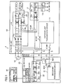
FIG. 1] FIG. 1 is a block diagram (in a suspended state) illustrating an electrical system of an air conditioner according to an embodiment. - [
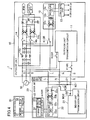
FIG. 2] FIG. 2 is a block diagram illustrating the periphery of a controller for controlling an external device of the embodiment. - [
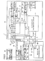
FIG. 3] FIG. 3 is a state transition diagram of the air conditioner of the embodiment. - [
FIG. 4] FIG. 4 illustrates states of relays when a circuit for charging a smoothing capacitor is formed. - [
FIG. 5] FIG. 5 illustrates states of the relays after transition to a charging state has been completed. - [
FIG. 6] FIG. 6 illustrates states of the relays in a wait state. - [
FIG. 7] FIG. 7 illustrates states of the relays in an operating state. - [
FIG. 8] FIG. 8 shows on and off states of an external device in a linkage mode. - [
FIG. 9] FIG. 9 shows on and off states of the external device in a non-linkage mode. - An embodiment of the present invention will be described with reference to the drawings. Note that the following embodiment of the preferred embodiment is merely illustrative in nature, and is not intended to limit the scope, applications, and use of the invention.
-
FIG. 1 is a block diagram illustrating an electrical system of an air conditioner (1) according to an embodiment of the present invention. As illustrated inFIG. 1 , the air conditioner (1) includes an outdoor unit (10), an indoor unit (20), and a remote controller (30). Although not shown, the outdoor unit (10) includes an electric compressor, an outdoor heat exchanger, an outdoor fan, and an expansion valve, for example. The indoor unit (20) includes an indoor heat exchanger and an indoor fan, for example. In the air conditioner (1), these components constitute a refrigerant circuit (not shown) that performs a refrigeration cycle. - In the air conditioner (1), the outdoor unit (10) receives an alternating current (AC) (a three-phase AC at 200 V in this example) from a commercial AC power supply (50) and uses the AC as electric power for circuits and the electric compressor in the outdoor unit (10). The outdoor unit (10) also supplies part of the three-phase AC corresponding to two phases to the indoor unit (20). Signal communication is performed between the outdoor unit (10) and the indoor unit (20) in order to control the outdoor unit (10) from the indoor unit (20). For this purpose, the air conditioner (1) includes, between the outdoor unit (10) and the indoor unit (20), three lines (indoor-outdoor communication lines): a power line (L) for transmitting AC power from the AC power supply (50), a signal line (S) for transmitting the signal, and a common line (N) to be shared by the transmission of the AC power and transmission of the signal.
- The outdoor unit (10), serving as an electrical system, includes a first outdoor power supply circuit (14), a second outdoor power supply circuit (12), an outdoor unit transmission circuit (11), an outdoor control circuit (13), and relays (K13R, K14R, K15R).
- The first outdoor power supply circuit (14) converts a three-phase AC received from the AC power supply (50) to a direct current (DC), and supplies the DC to a so-called intelligent power module (hereinafter referred to as an IPM) and an outdoor fan motor. The IPM converts the received DC to an AC having a predetermined frequency and a predetermined voltage, and supplies the AC to the motor of the electric compressor. The first outdoor power supply circuit (14) includes a noise filter (14a), two main relays (14b), two diode bridge circuits (14c), a reactor (14d), and a smoothing capacitor (14e).
- The noise filter (14a) includes a capacitor and a coil. The two main relays (14b) are respectively provided on the supply lines of an R-phase and a T-phase of the three-phase AC. The main relays (14b) are so-called A-contact relays. One of the two diode bridge circuits (14c) receives the R-phase and an S-phase of the three-phase AC, the other receives the S-phase and the T-phase of the three-phase AC, and each of the received phases of the AC is subjected to full-wave rectification. Outputs of the diode bridge circuits (14c) are input to the smoothing capacitor (14e) through the reactor (14d), and smoothed by the smoothing capacitor (14e). The DC smoothed by the smoothing capacitor (14e) is supplied to the IPM and the outdoor fan motor.
- The second outdoor power supply circuit (12) converts the two phases of the R-phase and S-phase of the three-phase AC to a DC (5 V in this example), and supplies the DC to the outdoor control circuit (13). The second outdoor power supply circuit (12) includes a diode bridge circuit (12a), a smoothing capacitor (12b), and a switching power supply (12c). One of the inputs of the diode bridge circuit (12a) is connected to the relay (K13R), which will be specifically described later, and the other input of the diode bridge circuit (12a) is connected to the S-phase of the three-phase AC. An output of the diode bridge circuit (12a) is smoothed by the smoothing capacitor (12b), and then input to the switching power supply (12c). The switching power supply (12c) converts an input DC to a predetermined voltage (5 V), and outputs the voltage to the outdoor control circuit (13).
- The outdoor unit transmission circuit (11) performs signal communication with the indoor unit transmission circuit (21). In this communication, based on a potential difference between the signal line (S) and the common line (N), communication of a binary digital signal is performed. An end of a communication circuit (not shown) in the outdoor unit transmission circuit (11) is connected to the common line (N), and the other end of the communication circuit is connected to the signal line (S) through the relay (K14R).
- The relay (K13R) is a relay for switching an AC supply path to the second outdoor power supply circuit (12). The relay (K13R) is a so-called C-contact relay. Switching of the relay (K13R) (whether current is supplied to the coil or not) is controlled by the outdoor control circuit (13).
- A movable contact of the relay (K13R) is connected to the input of the diode bridge circuit (12a). The normally closed contact is connected to the signal line (S), and the normally opened contact is connected to the R-phase of the three-phase AC. That is, when no current is supplied to the coil of the relay (K13R), the normally closed contact and the movable contact are connected to each other, and one of the inputs of the diode bridge circuit (12a) is connected to the signal line (S). Once electric power has been supplied to the coil of the relay (K13R), the movable contact and the normally opened contact are connected to each other, and an AC is input to the diode bridge circuit (12a) of the second outdoor power supply circuit (12).
- The relay (K14R) is a relay for connecting or disconnecting the signal line (S) and the outdoor unit transmission circuit (11). The relay (K14R) is a so-called A-contact relay. On/off operation of the relay (K14R) is controlled by the outdoor control circuit (13).
- The relay (K15R) is a relay for switching the supply of electric power to the outdoor unit transmission circuit (11) between on and off. The relay (K15R) is a so-called A-contact relay. On/off operation of the relay (K15R) is controlled by the outdoor control circuit (13).
- The outdoor control circuit (13) includes a microcomputer and a memory (not shown) storing a program for operating the microcomputer. In the outdoor control circuit (13), the outdoor unit transmission circuit (11), for example, controls the electric compressor and other components in response to a signal received from the indoor unit transmission circuit (21), and also controls start operation of the outdoor unit (10). When the air conditioner (1) is in a suspended state, power supply to the outdoor control circuit (13) is shut off, and operation thereof is stopped.
- The indoor unit (20), serving as an electrical system, includes an indoor power supply circuit (22), an indoor unit transmission circuit (21), an indoor control circuit (23), a relay (K2R), a first diode (D1), and a second diode (D2).
- The indoor power supply circuit (22) converts an AC supplied from the AC power supply (50) through the power line (L) and the common line (N) to a DC (a DC at 5 V in this example), and supplies the DC to the indoor control circuit (23). The indoor power supply circuit (22) includes a noise filter (22a), a diode bridge circuit (22b), a smoothing capacitor (22c), and a switching power supply (22d). The noise filter (22a) includes two coils. The diode bridge circuit (22b) performs full-wave rectification on an AC input from the power line (L) and the common line (N) through the noise filter (22a). The smoothing capacitor (22c) is, for example, an electrolytic capacitor, and smooths an output of the diode bridge circuit (22b). The switching power supply (22d) converts the DC smoothed by the smoothing capacitor (22c) to a predetermined voltage (5 V), and inputs the predetermined voltage to the indoor control circuit (23).
- As described above, the indoor unit transmission circuit (21) performs signal communication with the outdoor unit transmission circuit (11). In this communication, communication of a digital signal is performed based on the potential difference between the signal line (S) and the common line (N). Thus, an end of a communication circuit of the indoor unit transmission circuit (21) is connected to the signal line (S) through the second diode (D2), and the other end of the communication circuit is connected to the common line (N).
- The relay (K2R) is a so-called A-contact relay. The relay (K2R) and the first diode (D1) are provided in the indoor unit (20), and are serially connected to each other between the power line (L) and the signal line (S). The relay (K2R) serves as a switch for connecting or disconnecting the power line (L) and the signal line (S). On/off operation of the relay (K2R) is controlled by the indoor control circuit (23). The first diode (D1) inhibits an AC flowing into the indoor unit transmission circuit (21). The second diode (D2) inhibits an AC flowing out of the indoor unit transmission circuit (21).
- The indoor control circuit (23) includes a microcomputer and a memory (not shown) storing a program for operating the microcomputer, and receives electric power from the indoor power supply circuit (22) for control of an operating state of the air conditioner (1). The indoor control circuit (23) includes an I/F circuit (24) and an instruction section (25).
- The I/F circuit (24) is connected to the remote controller (30), and transmits and receives a signal to/from the remote controller (30).
- As illustrated in
FIG. 2 , the instruction section (25) is connected to the human detection sensor (26) and the external device controller (27). - The human detection sensor (26) is an infrared ray sensor, and detects the presence of a human in a room by using an energy variation of radiated infrared rays. The human detection sensor (26) is placed in the indoor unit (20), and is configured to perform detection in a conical region expanding from the human detection sensor (26) downward at a predetermined angle.
- The instruction section (25) receives a detection signal of the human detection sensor (26), determines whether a human is in a room or not, and outputs a result of the determination to the external device controller (27). Specifically, the instruction section (25) outputs a presence signal when detecting the presence of a human, and outputs an absence signal when detecting the absence of a human. In addition, the instruction section (25) outputs an operation signal to the external device controller (27) in an operating state, and outputs a suspension signal to an external device controller (27) in a suspended state.
- The external device controller (27) receives signals (i.e., the presence signal, the absence signal, the operation signal, and the suspension signal) from the instruction section (25), and thereby, turning on or off the external device. The external device controller (27) includes: a connection terminal (27a) connectable to an external device (e.g., a lighting unit in this example); and a switching section (27c) including a relay (27b) connected to the connection terminal (27a). The external device controller (27) receives signals (i.e., the presence signal and the operation signal) for turning the external device on, and thereby, turns on the relay (27b) of the switching section (27c). Consequently, the external device is turned on. The external device controller (27) receives the signals (i.e., the absence signal and the suspension signal) for turning the external device off, and thereby, turns off the relay (27b) of the switching section (27c). Consequently, the external device is turned off. The external device controller (27) and the instruction section (25) constitute a controller (28) that controls the external device based on a detection result of the human detection sensor (26). The external device controller (27) may be provided on a board on which the indoor control circuit (23) is located, or may be provided on a board different from a board on which the indoor control circuit (23) is located, such that the external device controller (27) can be connected to an external device.
- As illustrated in
FIG. 1 , the remote controller (30) is a so-called wired remote controller, and is connected to the indoor unit (20) through a transmission line. The remote controller (30) includes a communication section (31) and a setup section (32). - The communication section (31) is connected to the transmission line, and transmits and receives signals with the I/F circuit (24).
- In the setup section (32), the control mode of the external device is selected by a user. The control mode of the external device includes a linkage mode and a non-linkage mode. In the linkage mode, the external device is turned on when a human is in the room and is turned off when no human is in the room during operation (i.e., in an operating state), whereas the external device is turned off irrespective of whether a human is in the room or not during suspension of operation (i.e., in a suspended state). In the non-linkage mode, the external device is always on when a human is in the room, and is turned off when no human is in the room, in both operation and suspension of operation.
-
FIG. 3 is a state transition diagram of the air conditioner (1). The air conditioner (1) transitions among four states: a "suspended state," a "charging state," a "wait state," and an "operating state," which will be described later. - The suspended state is a standby state of the present invention, specifically a state in which electric power is supplied to the indoor unit (20) and no electric power is supplied to the outdoor unit (10).
- For example, in the suspended state of this embodiment, power consumption of the whole air conditioner (1) is the minimum. Specifically, in the suspended state of this embodiment, the outdoor unit (10) receives and supplies electric power to the indoor unit (20), but no electric power is supplied to, for example, the circuits and the electric compressor in the outdoor unit (10). In this manner, in the suspended state, power supply to the circuits in the outdoor unit (10) is shut off, thereby reducing standby power consumption.
- On the other hand, standby power consumption of the indoor unit (20) is the minimum, and in this embodiment, part of the human detection sensor (26), the instruction section (25), the external device controller (27), and the remote controller (30) responsible for signal reception from the remote controller (30) receives electric power from the indoor power supply circuit (22) and operates.
- Standby power consumption of the remote controller (30) is also the minimum, and can accept predetermined indications of operation by a user. The degrees of power consumption (standby power consumption) of the indoor unit (20) and the remote controller (30) are not limited to those described herein.
- For the outdoor unit (10), the charging state refers to a state from start of charging of the second outdoor power supply circuit (12) to start of signal transmission between the outdoor unit transmission circuit (11) and the indoor unit transmission circuit (21).
- The degrees of power consumption of the indoor unit (20) and the remote controller (30) in the charging state are similar to those in the suspended state.
- The wait state refers to a state in which the air conditioner is not in the charging state when operation is started, and a state to which the air conditioner transitions from an operating state (which will be described later) when operation is stopped. In both cases, the outdoor unit (10) is ready for, i.e., can promptly transition to, the operating state (which will be described later) through the wait state. In the wait state, the outdoor unit transmission circuit (11) and the outdoor control circuit (13) can also operate. In particular, the wait state at an operation stop (i.e., the wait state transitioned from the operating state) is provided in order to uniformize the refrigerant pressure in the electric compressor and to be used for scheduled operation in which an operation start and an operation stop are repeatedly performed.
- The operating state refers to a state in which the first outdoor power supply circuit (14) supplies electric power to the IPM and the fan motor so that the electric compressor and the outdoor fan are operable or in operation.
- The degree of power consumption of the remote controller (30) in the operating state is similar to that in the charging state. On the other hand, the degree of power consumption of the indoor unit (20) in the operating state is higher than those in the other states because the indoor fan and other components are in the operating states.
- In an operation start of the air conditioner (1), the state transitions from the suspended state to the charging state, the wait state, and the operating state in this order (as indicated by arrows of continuous lines in
FIG. 3 ). Operation from the suspended state to the operating state will now be described. - First, a state of the electrical system in the suspended state will be described.
FIG. 1 illustrates states of the relays in the suspended state. - In the outdoor unit (10), the main relays (14b) is off, and no power is supplied from the first outdoor power supply circuit (14) to any of the IPM and the outdoor fan motor. The relay (K14R) and the relay (K15R) are off. That is, connection of the outdoor unit transmission circuit (11) to the signal line (S) is broken, and supply of electric power is shut off. In the relay (K13R), the normally closed contact point and the movable contact are connected to each other. That is, one of the inputs of the diode bridge circuit (12a) of the second outdoor power supply circuit (12) is connected to the signal line (S). In this state, no current flows in the second outdoor power supply circuit (12), and no electric power is supplied to the outdoor control circuit (13), either. In this manner, supply of electric power to the outdoor unit (10) is shut off.
- In the indoor unit (20), the relay (K2R) is off, and the signal line (S) and the power line (L) are not electrically connected to each other. In the indoor unit (20), the human detection sensor (26), the instruction section (25), the external device controller (27), and part of the indoor unit (20) responsible for signal reception from the remote controller (30) receive electric power from the indoor power supply circuit (22) and operates.
-
FIG. 4 illustrates states of the relays when a circuit for charging the smoothing capacitor (12b) of the second outdoor power supply circuit (12) is formed.FIG. 5 illustrates states of the relays after transition to the charging state has been completed. - when a user presses an operation button (not shown) of the remote controller (30), an operation start signal is transmitted from the communication section (31) to the indoor unit (20).
- In the indoor unit (20), when the I/F circuit (24) receives the operation start signal, the indoor control circuit (23) turns the relay (K2R) on. Then, a path from the R-phase of the three-phase AC to the second outdoor power supply circuit (12) via the power line (L), the relay (K2R), the first diode (D1), the signal line (S), and the relay (K13R) is formed. In this manner, a circuit for charging the smoothing capacitor (12b) of the second outdoor power supply circuit (12) is formed (see
FIG. 4 ). - In the outdoor unit (10), when the smoothing capacitor (12b) is charged and input of electric power to the switching power supply (12c) is stabilized so that the switching power supply (12c) is allowed to output a specific DC voltage (5V in this example), the outdoor control circuit (13) is started. The outdoor control circuit (13) that has been started causes a current to flow in the coil of the relay (K13R) so that the normally opened contact point and the movable contact are connected to each other. In this manner, one of the inputs of the diode bridge circuit (12a) is connected to the R-phase of the three-phase AC via a power transmission path in the outdoor unit (10). That is, the outdoor control circuit (13) is switched to a state in which electric power is supplied from the AC power supply (50) not passing through the signal line (S) (see
FIG. 5 ). Then, transition from the suspended state to the charging state is completed. -
FIG. 6 illustrates states of the relays when transition to the wait state is completed. In the indoor unit (20), after a lapse of a predetermined time (a time sufficient for startup of the outdoor control circuit (13)) from turning on of the relay (K2R), the relay (K2R) is turned off. In this manner, the signal line (S) can be used for signal transmission. - In the outdoor unit (10), after the relay (K2R) has been turned off, the outdoor control circuit (13) turns the relay (K15R) on so that electric power is supplied to the outdoor unit transmission circuit (11), and the outdoor control circuit (13) also turns the relay (K14R) on. In this manner, the communication circuit in the outdoor unit transmission circuit (11) is connected to the indoor unit transmission circuit (21) through the signal line (S) and the common line (N), and thus, becomes able to communicate with the indoor unit transmission circuit (21). Consequently, the air conditioner (1) transitions to a state (i.e., a wait state) in which the air conditioner (1) is ready for transition to the operating state promptly through the charging state.
-
FIG. 7 illustrates states of the relays in the operating state. In transition from the wait state to the operating state, the outdoor control circuit (13) turns the two main relays (14b) on. Then, the first outdoor power supply circuit (14) supplies electric power to the IPM and the outdoor fan motor, and the electric compressor and other components come to be in the operating state and performs, for example, cooling operation. - In operation stop of the air conditioner (1), the state transitions from the operating state to the wait state and then to the suspended state (as indicated by arrows of dotted lines in
FIG. 3 ). Operation from the operating state to the suspended state will now be described in order. - When a user presses an operation button of the remote controller (30) in the operating state, the remote controller (30) transmits an operation stop signal to the indoor unit (20), and then the indoor unit (20) transmits an operation stop signal to the outdoor unit (10).
- In the outdoor unit (10), in response to the operation stop signal, the outdoor control circuit (13) turns the main relays (14b) of the first outdoor power supply circuit (14) off (see
FIG. 6 ). Thus, electric power supply to the IPM and the outdoor fan motor is shut off, and the electric compressor and other components are stopped. In this manner, transition from the operating state to the wait state is completed. - In the wait state, first, the remote controller (30) determines whether to transition to the suspended state or not depending on whether a predetermined time has elapsed or not. After a lapse of the predetermined time, the remote controller (30) determines that transition to the suspended state is allowed. Then, the remote controller (30) transmits a shut-off request signal to the indoor unit (20), and the indoor unit (20) transmits the shut-off request signal to the outdoor unit (10).
- In the outdoor unit (10), when the outdoor unit transmission circuit (11) receives the shut-off request signal, the outdoor control circuit (13) turns the relay (K14R) and the relay (K15R) off. In addition, the outdoor control circuit (13) connects the normally closed contact point and the movable contact of the relay (K13R) to each other, and thus, supply of electric power to the second outdoor power supply circuit (12) is shut off (see
FIG. 1 ). In this manner, transition to the suspended state is completed. - In the air conditioner (1) of this embodiment, the control mode of the external device is set in the setup section (32) of the remote controller (30). The user selects one of the linkage mode or the non-linkage mode, and inputs the selected mode.
- In the case of selecting the linkage mode, the instruction section (25) outputs an operation signal to the external device controller (27) in the operating state, and the instruction section (25) outputs a suspension signal to the external device controller (27) in the suspended state.
- Specifically, when operation start of the air conditioner (1) is performed so that the state transitions to the operating state, the instruction section (25) outputs an operation signal to the external device controller (27). In the external device controller (27), the relay (27b) is turned on in response to the operation signal, and thereby, the external device is turned on.
- On the other hand, when operation stop of the air conditioner (1) is performed so that the state transitions to the suspended state, the instruction section (25) outputs a suspension signal to the external device controller (27). In the external device controller (27), the relay (27b) is turned off in response to the suspension signal, and thereby, the external device is turned off.
- Then, control of the external device by using the human detection sensor (26) will be described.
- When the human detection sensor (26) detects the presence/absence of a human in the operating state, the detection signal is input to the instruction section (25). Based on this detection signal, the instruction section (25) determines whether a human is present or not. If it is determined that a human is present, the instruction section (25) outputs an operation signal to the external device controller (27). In the external device controller (27), in response to the operation signal, the relay (27b) is turned on, and thereby, the external device is kept on. On the other hand, if it is determined that a human is absent, operation stop is started, and the state then transitions to the suspended state. Once the transition to the suspended state has been completed, the instruction section (25) outputs a suspension signal to the external device controller (27). In the external device controller (27), in response to the suspension signal, the relay (27b) is turned off, and thereby, the external device is turned off. In this manner, in the operating state, control of the external device based on the detection result of the human detection sensor (26) is permitted.
- On the other hand, when the human detection sensor (26) detects the presence/absence of a human in the suspended state, the detection signal is input to the instruction section (25). The instruction section (25), however, does not determine whether a human is present or not, based on the detection signal. Thus, control of the external device based on the detection result of the human detection sensor (26) is inhibited, and the external device is kept off.
- In the foregoing manner, in the case of selecting the linkage mode, as illustrated in
FIG. 8 , the external device is turned on or off depending on the presence/absence of a human only during operation (i.e., only in the operating state), and the external device is always off during suspension of operation (i.e., in the suspended state). - In the case of selecting the non-linkage mode, irrespective of the state of the air conditioner (1), the instruction section (25) outputs a presence signal to the external device controller (27) when a human is present, and the instruction section (25) outputs an absence signal to the external device controller (27) when a human is absent.
- Specifically, when the human detection sensor (26) detects the presence/absence of a human, the detection signal is input to the instruction section (25). Based on the detection signal, the instruction section (25) determines whether a human is present or not. If it is determined that a human is present, the instruction section (25) outputs a presence signal to the external device controller (27). In the external device controller (27), the relay (27b) is turned on in response to the presence signal, and thereby, the external device is turned on. On the other hand, if it is determined that a human is absent, the instruction section (25) outputs an absence signal to the external device controller (27). In the external device controller (27), the relay (27b) is turned off in response to the absence signal, and thereby, the external device is turned off. Thus, control of the external device based on the detection result of the human detection sensor (26) is permitted.
- In the foregoing manner, in the case of selecting the non-linkage mode, as illustrated in
FIG. 9 , irrespective of the state, i.e., during operation or suspension of operation, of the air conditioner (1), the external device is always turned on or off depending on whether a human is present or not. - In this embodiment, the user can select the non-linkage mode in which on/off control of the external device is permitted during suspension of operation as well as during operation, in addition to the linkage mode in which on/off control of the external device is permitted during operation and on/off control of the external device is inhibited during suspension of operation,. Thus, on/off control of the external device can be performed by using the human detection sensor (26) during suspension of operation, and as a result, convenience for the user can be enhanced.
- In addition, in this embodiment, in operation stop, the state transitions to the suspended state in which supply of electric power to the outdoor unit (10) is shut off. Thus, even in the case of on/off control of the external device performed in suspension of operation by selecting the non-linkage mode, power consumption (standby power) of the whole air conditioner (1) in the suspension of operation can be reduced.
- Further, in this embodiment, in the case of selecting the linkage mode, not only the external device but also the air conditioner (1) itself is stopped when a human moves out of the room, i.e., becomes absent in the room. Thus, a failure in stopping the air conditioner (1) when a human moves out of the room can be prevented.
- In the above embodiment, the lighting unit is used as an external device. However, the external device is not limited to the lighting unit, and may be a humidifier, a ventilation device, an alarm, or a monitor, for example.
- In addition, in the control of the above embodiment, the external device is turned on when a human is in the room, and is turned off when no human is in the room. In contrast, the external device may be turned off when a human is in the room, and turned off when no human is in the room.
- In the above embodiment, on/off of the lighting unit serving as the external device is performed. However, control of the external device is not limited to on/off control, and may be, for example, adjustment of an output from the external device, such as changing of the luminance of the lighting unit.
- As described above, the present invention is useful for air conditioners for conditioning air in the room.
-
- 1
- air conditioner
- 10
- outdoor unit
- 20
- indoor unit
- 26
- human detection sensor
- 28
- controller
- 32
- setup section
Claims (2)
- An air conditioner comprising:an indoor unit (20);an outdoor unit (10); anda human detection sensor (26) that is located in the indoor unit (20) and detects presence of a human in a room, whereinthe indoor unit (20) includes a controller (28) that controls an external device based on a detection result of the human detection sensor (26), andthe air conditioner further comprises a setup section (32) that enables a user to select one of
a linkage mode in which the controller (28) permits control of the external device based on the detection result of the human detection sensor (26) while the air conditioner is in operation and the controller (28) inhibits control of the external device based on the detection result of the human detection sensor (26) while the air conditioner is stopped or
a non-linkage mode in which the controller (28) permits control of the external device based on the detection result of the human detection sensor (26) irrespective of whether the air conditioner is in operation or not. - The air conditioner of claim 1, wherein
the air conditioner is configured to transition to a standby state in which electric power is supplied to the human detection sensor (26) and the controller (28) and no electric power is supplied to the outdoor unit (10) while the air conditioner is stopped, and
in the non-linkage mode, the controller (28) permits control of the external device based on the detection result of the human detection sensor (26) when the air conditioner is in the standby state.
Applications Claiming Priority (2)
| Application Number | Priority Date | Filing Date | Title |
|---|---|---|---|
| JP2012026866A JP5403083B2 (en) | 2012-02-10 | 2012-02-10 | Air conditioner |
| PCT/JP2013/000713 WO2013118513A1 (en) | 2012-02-10 | 2013-02-08 | Air conditioner |
Publications (3)
| Publication Number | Publication Date |
|---|---|
| EP2806229A1 true EP2806229A1 (en) | 2014-11-26 |
| EP2806229A4 EP2806229A4 (en) | 2015-11-25 |
| EP2806229B1 EP2806229B1 (en) | 2017-03-29 |
Family
ID=48947283
Family Applications (1)
| Application Number | Title | Priority Date | Filing Date |
|---|---|---|---|
| EP13747298.1A Not-in-force EP2806229B1 (en) | 2012-02-10 | 2013-02-08 | Air conditioner |
Country Status (6)
| Country | Link |
|---|---|
| US (1) | US9989272B2 (en) |
| EP (1) | EP2806229B1 (en) |
| JP (1) | JP5403083B2 (en) |
| CN (1) | CN104081132B (en) |
| ES (1) | ES2621925T3 (en) |
| WO (1) | WO2013118513A1 (en) |
Families Citing this family (8)
| Publication number | Priority date | Publication date | Assignee | Title |
|---|---|---|---|---|
| DE112015006249T5 (en) * | 2015-03-03 | 2017-11-16 | Mitsubishi Electric Corporation | Communication system, transmitting device and receiving device |
| JP6498275B2 (en) * | 2015-03-27 | 2019-04-10 | 三菱電機株式会社 | Air conditioner |
| JP6674083B2 (en) * | 2015-06-19 | 2020-04-01 | シンフォニアテクノロジー株式会社 | Gas supply target device, gas supply system, and method of controlling gas supply system |
| KR101737364B1 (en) * | 2015-08-31 | 2017-05-18 | 엘지전자 주식회사 | Air conditioner including the same |
| KR101951675B1 (en) * | 2017-03-28 | 2019-02-25 | 엘지전자 주식회사 | Air conditioner having power saving function |
| JP7147147B2 (en) * | 2017-09-29 | 2022-10-05 | Toto株式会社 | remote control system |
| WO2021234989A1 (en) * | 2020-05-18 | 2021-11-25 | 三菱電機株式会社 | Sensor power source control system and air cleaner |
| CN117321344A (en) * | 2022-04-27 | 2023-12-29 | 日立江森自控空调有限公司 | air conditioner |
Family Cites Families (8)
| Publication number | Priority date | Publication date | Assignee | Title |
|---|---|---|---|---|
| JPH05203218A (en) * | 1992-01-30 | 1993-08-10 | Mitsubishi Electric Corp | Air conditioner with lighting |
| CN1191293A (en) * | 1998-03-24 | 1998-08-26 | 吴志源 | Intelligent fuzzy logic controlling method for air conditioner |
| US6980079B1 (en) * | 1999-07-13 | 2005-12-27 | Matsushita Electric Industrial Co., Ltd. | Control network system of household electric appliance |
| JP2004150731A (en) | 2002-10-31 | 2004-05-27 | Daikin Ind Ltd | Air conditioner |
| JP4254524B2 (en) * | 2003-12-22 | 2009-04-15 | パナソニック電工株式会社 | Automatic switch with hot wire sensor |
| US20100070089A1 (en) * | 2008-09-15 | 2010-03-18 | Johnson Controls Technology Company | Hvac controller user interfaces |
| JP2010164231A (en) * | 2009-01-15 | 2010-07-29 | Fujitsu General Ltd | Air conditioner and remote control device used for the same |
| CN201628340U (en) * | 2010-02-25 | 2010-11-10 | 济南赛英立德电子科技有限公司 | Air-conditioner energy saving controller of double control modes |
-
2012
- 2012-02-10 JP JP2012026866A patent/JP5403083B2/en not_active Expired - Fee Related
-
2013
- 2013-02-08 WO PCT/JP2013/000713 patent/WO2013118513A1/en not_active Ceased
- 2013-02-08 CN CN201380007561.8A patent/CN104081132B/en not_active Expired - Fee Related
- 2013-02-08 US US14/375,312 patent/US9989272B2/en active Active
- 2013-02-08 ES ES13747298.1T patent/ES2621925T3/en active Active
- 2013-02-08 EP EP13747298.1A patent/EP2806229B1/en not_active Not-in-force
Also Published As
| Publication number | Publication date |
|---|---|
| EP2806229A4 (en) | 2015-11-25 |
| CN104081132A (en) | 2014-10-01 |
| US9989272B2 (en) | 2018-06-05 |
| JP5403083B2 (en) | 2014-01-29 |
| US20150013362A1 (en) | 2015-01-15 |
| WO2013118513A1 (en) | 2013-08-15 |
| ES2621925T3 (en) | 2017-07-05 |
| EP2806229B1 (en) | 2017-03-29 |
| CN104081132B (en) | 2015-07-22 |
| JP2013164189A (en) | 2013-08-22 |
Similar Documents
| Publication | Publication Date | Title |
|---|---|---|
| EP2806229B1 (en) | Air conditioner | |
| EP2803917B1 (en) | Air conditioning device | |
| EP2803918B1 (en) | Air conditioning device | |
| US9696734B2 (en) | Active power stealing | |
| US9097448B2 (en) | Air conditioning system and method for controlling operation thereof | |
| KR950012150B1 (en) | Current controller of air conditioner system | |
| JP2013137118A (en) | Air conditioning device | |
| JP2013137119A (en) | Air conditioning device | |
| US11268717B2 (en) | Thermostat power monitoring, mitigation and alert | |
| JPH03245743A (en) | Power controller for home bus system | |
| JP5804009B2 (en) | Air conditioner | |
| JP5772588B2 (en) | Air conditioner | |
| JP2013137114A (en) | Air conditioning device | |
| CN205245452U (en) | Variable frequency air conditioner controlling means , terminal and system based on thermoregulator | |
| JP2013137113A (en) | Air conditioning device | |
| CN205245453U (en) | Variable frequency air conditioner controlling means , terminal and system based on thermoregulator | |
| JP2015055450A (en) | Air conditioning device | |
| JP5772577B2 (en) | Air conditioner | |
| JP5772579B2 (en) | Air conditioner | |
| WO2024127599A1 (en) | Air-conditioning device, outdoor unit, indoor unit, and air-conditioning system | |
| JP2011085322A (en) | Air-conditioning auxiliary system and air-conditioning interlocking control system |
Legal Events
| Date | Code | Title | Description |
|---|---|---|---|
| PUAI | Public reference made under article 153(3) epc to a published international application that has entered the european phase |
Free format text: ORIGINAL CODE: 0009012 |
|
| 17P | Request for examination filed |
Effective date: 20140812 |
|
| AK | Designated contracting states |
Kind code of ref document: A1 Designated state(s): AL AT BE BG CH CY CZ DE DK EE ES FI FR GB GR HR HU IE IS IT LI LT LU LV MC MK MT NL NO PL PT RO RS SE SI SK SM TR |
|
| DAX | Request for extension of the european patent (deleted) | ||
| RA4 | Supplementary search report drawn up and despatched (corrected) |
Effective date: 20151022 |
|
| RIC1 | Information provided on ipc code assigned before grant |
Ipc: F24F 11/02 20060101AFI20151016BHEP Ipc: F24F 11/00 20060101ALI20151016BHEP |
|
| GRAP | Despatch of communication of intention to grant a patent |
Free format text: ORIGINAL CODE: EPIDOSNIGR1 |
|
| INTG | Intention to grant announced |
Effective date: 20161010 |
|
| GRAS | Grant fee paid |
Free format text: ORIGINAL CODE: EPIDOSNIGR3 |
|
| STAA | Information on the status of an ep patent application or granted ep patent |
Free format text: STATUS: GRANT OF PATENT IS INTENDED |
|
| GRAA | (expected) grant |
Free format text: ORIGINAL CODE: 0009210 |
|
| STAA | Information on the status of an ep patent application or granted ep patent |
Free format text: STATUS: THE PATENT HAS BEEN GRANTED |
|
| AK | Designated contracting states |
Kind code of ref document: B1 Designated state(s): AL AT BE BG CH CY CZ DE DK EE ES FI FR GB GR HR HU IE IS IT LI LT LU LV MC MK MT NL NO PL PT RO RS SE SI SK SM TR |
|
| REG | Reference to a national code |
Ref country code: GB Ref legal event code: FG4D |
|
| REG | Reference to a national code |
Ref country code: CH Ref legal event code: EP |
|
| REG | Reference to a national code |
Ref country code: AT Ref legal event code: REF Ref document number: 880153 Country of ref document: AT Kind code of ref document: T Effective date: 20170415 |
|
| REG | Reference to a national code |
Ref country code: IE Ref legal event code: FG4D |
|
| REG | Reference to a national code |
Ref country code: DE Ref legal event code: R096 Ref document number: 602013019185 Country of ref document: DE |
|
| REG | Reference to a national code |
Ref country code: ES Ref legal event code: FG2A Ref document number: 2621925 Country of ref document: ES Kind code of ref document: T3 Effective date: 20170705 |
|
| PG25 | Lapsed in a contracting state [announced via postgrant information from national office to epo] |
Ref country code: GR Free format text: LAPSE BECAUSE OF FAILURE TO SUBMIT A TRANSLATION OF THE DESCRIPTION OR TO PAY THE FEE WITHIN THE PRESCRIBED TIME-LIMIT Effective date: 20170630 Ref country code: FI Free format text: LAPSE BECAUSE OF FAILURE TO SUBMIT A TRANSLATION OF THE DESCRIPTION OR TO PAY THE FEE WITHIN THE PRESCRIBED TIME-LIMIT Effective date: 20170329 Ref country code: HR Free format text: LAPSE BECAUSE OF FAILURE TO SUBMIT A TRANSLATION OF THE DESCRIPTION OR TO PAY THE FEE WITHIN THE PRESCRIBED TIME-LIMIT Effective date: 20170329 Ref country code: NO Free format text: LAPSE BECAUSE OF FAILURE TO SUBMIT A TRANSLATION OF THE DESCRIPTION OR TO PAY THE FEE WITHIN THE PRESCRIBED TIME-LIMIT Effective date: 20170629 Ref country code: LT Free format text: LAPSE BECAUSE OF FAILURE TO SUBMIT A TRANSLATION OF THE DESCRIPTION OR TO PAY THE FEE WITHIN THE PRESCRIBED TIME-LIMIT Effective date: 20170329 |
|
| REG | Reference to a national code |
Ref country code: NL Ref legal event code: MP Effective date: 20170329 |
|
| REG | Reference to a national code |
Ref country code: AT Ref legal event code: MK05 Ref document number: 880153 Country of ref document: AT Kind code of ref document: T Effective date: 20170329 |
|
| PG25 | Lapsed in a contracting state [announced via postgrant information from national office to epo] |
Ref country code: BG Free format text: LAPSE BECAUSE OF FAILURE TO SUBMIT A TRANSLATION OF THE DESCRIPTION OR TO PAY THE FEE WITHIN THE PRESCRIBED TIME-LIMIT Effective date: 20170629 Ref country code: LV Free format text: LAPSE BECAUSE OF FAILURE TO SUBMIT A TRANSLATION OF THE DESCRIPTION OR TO PAY THE FEE WITHIN THE PRESCRIBED TIME-LIMIT Effective date: 20170329 Ref country code: SE Free format text: LAPSE BECAUSE OF FAILURE TO SUBMIT A TRANSLATION OF THE DESCRIPTION OR TO PAY THE FEE WITHIN THE PRESCRIBED TIME-LIMIT Effective date: 20170329 Ref country code: RS Free format text: LAPSE BECAUSE OF FAILURE TO SUBMIT A TRANSLATION OF THE DESCRIPTION OR TO PAY THE FEE WITHIN THE PRESCRIBED TIME-LIMIT Effective date: 20170329 |
|
| PG25 | Lapsed in a contracting state [announced via postgrant information from national office to epo] |
Ref country code: NL Free format text: LAPSE BECAUSE OF FAILURE TO SUBMIT A TRANSLATION OF THE DESCRIPTION OR TO PAY THE FEE WITHIN THE PRESCRIBED TIME-LIMIT Effective date: 20170329 |
|
| PG25 | Lapsed in a contracting state [announced via postgrant information from national office to epo] |
Ref country code: SK Free format text: LAPSE BECAUSE OF FAILURE TO SUBMIT A TRANSLATION OF THE DESCRIPTION OR TO PAY THE FEE WITHIN THE PRESCRIBED TIME-LIMIT Effective date: 20170329 Ref country code: AT Free format text: LAPSE BECAUSE OF FAILURE TO SUBMIT A TRANSLATION OF THE DESCRIPTION OR TO PAY THE FEE WITHIN THE PRESCRIBED TIME-LIMIT Effective date: 20170329 Ref country code: CZ Free format text: LAPSE BECAUSE OF FAILURE TO SUBMIT A TRANSLATION OF THE DESCRIPTION OR TO PAY THE FEE WITHIN THE PRESCRIBED TIME-LIMIT Effective date: 20170329 Ref country code: EE Free format text: LAPSE BECAUSE OF FAILURE TO SUBMIT A TRANSLATION OF THE DESCRIPTION OR TO PAY THE FEE WITHIN THE PRESCRIBED TIME-LIMIT Effective date: 20170329 Ref country code: RO Free format text: LAPSE BECAUSE OF FAILURE TO SUBMIT A TRANSLATION OF THE DESCRIPTION OR TO PAY THE FEE WITHIN THE PRESCRIBED TIME-LIMIT Effective date: 20170329 |
|
| REG | Reference to a national code |
Ref country code: DE Ref legal event code: R079 Ref document number: 602013019185 Country of ref document: DE Free format text: PREVIOUS MAIN CLASS: F24F0011020000 Ipc: F24F0011890000 |
|
| PG25 | Lapsed in a contracting state [announced via postgrant information from national office to epo] |
Ref country code: SM Free format text: LAPSE BECAUSE OF FAILURE TO SUBMIT A TRANSLATION OF THE DESCRIPTION OR TO PAY THE FEE WITHIN THE PRESCRIBED TIME-LIMIT Effective date: 20170329 Ref country code: PL Free format text: LAPSE BECAUSE OF FAILURE TO SUBMIT A TRANSLATION OF THE DESCRIPTION OR TO PAY THE FEE WITHIN THE PRESCRIBED TIME-LIMIT Effective date: 20170329 Ref country code: PT Free format text: LAPSE BECAUSE OF FAILURE TO SUBMIT A TRANSLATION OF THE DESCRIPTION OR TO PAY THE FEE WITHIN THE PRESCRIBED TIME-LIMIT Effective date: 20170731 Ref country code: IS Free format text: LAPSE BECAUSE OF FAILURE TO SUBMIT A TRANSLATION OF THE DESCRIPTION OR TO PAY THE FEE WITHIN THE PRESCRIBED TIME-LIMIT Effective date: 20170729 |
|
| REG | Reference to a national code |
Ref country code: DE Ref legal event code: R097 Ref document number: 602013019185 Country of ref document: DE |
|
| REG | Reference to a national code |
Ref country code: FR Ref legal event code: PLFP Year of fee payment: 6 |
|
| PG25 | Lapsed in a contracting state [announced via postgrant information from national office to epo] |
Ref country code: DK Free format text: LAPSE BECAUSE OF FAILURE TO SUBMIT A TRANSLATION OF THE DESCRIPTION OR TO PAY THE FEE WITHIN THE PRESCRIBED TIME-LIMIT Effective date: 20170329 |
|
| PLBE | No opposition filed within time limit |
Free format text: ORIGINAL CODE: 0009261 |
|
| STAA | Information on the status of an ep patent application or granted ep patent |
Free format text: STATUS: NO OPPOSITION FILED WITHIN TIME LIMIT |
|
| 26N | No opposition filed |
Effective date: 20180103 |
|
| PG25 | Lapsed in a contracting state [announced via postgrant information from national office to epo] |
Ref country code: SI Free format text: LAPSE BECAUSE OF FAILURE TO SUBMIT A TRANSLATION OF THE DESCRIPTION OR TO PAY THE FEE WITHIN THE PRESCRIBED TIME-LIMIT Effective date: 20170329 |
|
| REG | Reference to a national code |
Ref country code: CH Ref legal event code: PL |
|
| PG25 | Lapsed in a contracting state [announced via postgrant information from national office to epo] |
Ref country code: MC Free format text: LAPSE BECAUSE OF FAILURE TO SUBMIT A TRANSLATION OF THE DESCRIPTION OR TO PAY THE FEE WITHIN THE PRESCRIBED TIME-LIMIT Effective date: 20170329 |
|
| REG | Reference to a national code |
Ref country code: IE Ref legal event code: MM4A |
|
| REG | Reference to a national code |
Ref country code: BE Ref legal event code: MM Effective date: 20180228 |
|
| PG25 | Lapsed in a contracting state [announced via postgrant information from national office to epo] |
Ref country code: LI Free format text: LAPSE BECAUSE OF NON-PAYMENT OF DUE FEES Effective date: 20180228 Ref country code: LU Free format text: LAPSE BECAUSE OF NON-PAYMENT OF DUE FEES Effective date: 20180208 Ref country code: CH Free format text: LAPSE BECAUSE OF NON-PAYMENT OF DUE FEES Effective date: 20180228 |
|
| PG25 | Lapsed in a contracting state [announced via postgrant information from national office to epo] |
Ref country code: IE Free format text: LAPSE BECAUSE OF NON-PAYMENT OF DUE FEES Effective date: 20180208 |
|
| PG25 | Lapsed in a contracting state [announced via postgrant information from national office to epo] |
Ref country code: BE Free format text: LAPSE BECAUSE OF NON-PAYMENT OF DUE FEES Effective date: 20180228 |
|
| PG25 | Lapsed in a contracting state [announced via postgrant information from national office to epo] |
Ref country code: MT Free format text: LAPSE BECAUSE OF NON-PAYMENT OF DUE FEES Effective date: 20180208 |
|
| PG25 | Lapsed in a contracting state [announced via postgrant information from national office to epo] |
Ref country code: TR Free format text: LAPSE BECAUSE OF FAILURE TO SUBMIT A TRANSLATION OF THE DESCRIPTION OR TO PAY THE FEE WITHIN THE PRESCRIBED TIME-LIMIT Effective date: 20170329 |
|
| PG25 | Lapsed in a contracting state [announced via postgrant information from national office to epo] |
Ref country code: HU Free format text: LAPSE BECAUSE OF FAILURE TO SUBMIT A TRANSLATION OF THE DESCRIPTION OR TO PAY THE FEE WITHIN THE PRESCRIBED TIME-LIMIT; INVALID AB INITIO Effective date: 20130208 |
|
| PG25 | Lapsed in a contracting state [announced via postgrant information from national office to epo] |
Ref country code: CY Free format text: LAPSE BECAUSE OF FAILURE TO SUBMIT A TRANSLATION OF THE DESCRIPTION OR TO PAY THE FEE WITHIN THE PRESCRIBED TIME-LIMIT Effective date: 20170329 Ref country code: MK Free format text: LAPSE BECAUSE OF NON-PAYMENT OF DUE FEES Effective date: 20170329 |
|
| PG25 | Lapsed in a contracting state [announced via postgrant information from national office to epo] |
Ref country code: AL Free format text: LAPSE BECAUSE OF FAILURE TO SUBMIT A TRANSLATION OF THE DESCRIPTION OR TO PAY THE FEE WITHIN THE PRESCRIBED TIME-LIMIT Effective date: 20170329 |
|
| P01 | Opt-out of the competence of the unified patent court (upc) registered |
Effective date: 20230525 |
|
| PGFP | Annual fee paid to national office [announced via postgrant information from national office to epo] |
Ref country code: ES Payment date: 20240304 Year of fee payment: 12 |
|
| PGFP | Annual fee paid to national office [announced via postgrant information from national office to epo] |
Ref country code: DE Payment date: 20231228 Year of fee payment: 12 Ref country code: GB Payment date: 20240109 Year of fee payment: 12 |
|
| PGFP | Annual fee paid to national office [announced via postgrant information from national office to epo] |
Ref country code: IT Payment date: 20240111 Year of fee payment: 12 Ref country code: FR Payment date: 20240103 Year of fee payment: 12 |
|
| REG | Reference to a national code |
Ref country code: DE Ref legal event code: R119 Ref document number: 602013019185 Country of ref document: DE |
|
| GBPC | Gb: european patent ceased through non-payment of renewal fee |
Effective date: 20250208 |
|
| PG25 | Lapsed in a contracting state [announced via postgrant information from national office to epo] |
Ref country code: DE Free format text: LAPSE BECAUSE OF NON-PAYMENT OF DUE FEES Effective date: 20250902 |
|
| PG25 | Lapsed in a contracting state [announced via postgrant information from national office to epo] |
Ref country code: GB Free format text: LAPSE BECAUSE OF NON-PAYMENT OF DUE FEES Effective date: 20250208 |
|
| PG25 | Lapsed in a contracting state [announced via postgrant information from national office to epo] |
Ref country code: FR Free format text: LAPSE BECAUSE OF NON-PAYMENT OF DUE FEES Effective date: 20250228 Ref country code: IT Free format text: LAPSE BECAUSE OF NON-PAYMENT OF DUE FEES Effective date: 20250208 |
|
| REG | Reference to a national code |
Ref country code: ES Ref legal event code: FD2A Effective date: 20260327 |
|
| PG25 | Lapsed in a contracting state [announced via postgrant information from national office to epo] |
Ref country code: ES Free format text: LAPSE BECAUSE OF NON-PAYMENT OF DUE FEES Effective date: 20250209 |