EP2806219B1 - Regulator device for a choke element - Google Patents
Regulator device for a choke element Download PDFInfo
- Publication number
- EP2806219B1 EP2806219B1 EP14158338.5A EP14158338A EP2806219B1 EP 2806219 B1 EP2806219 B1 EP 2806219B1 EP 14158338 A EP14158338 A EP 14158338A EP 2806219 B1 EP2806219 B1 EP 2806219B1
- Authority
- EP
- European Patent Office
- Prior art keywords
- arm
- regulator
- handle
- tooth
- choke element
- Prior art date
- Legal status (The legal status is an assumption and is not a legal conclusion. Google has not performed a legal analysis and makes no representation as to the accuracy of the status listed.)
- Not-in-force
Links
- 239000012528 membrane Substances 0.000 claims description 5
- 239000012530 fluid Substances 0.000 description 8
- 238000003780 insertion Methods 0.000 description 8
- 230000037431 insertion Effects 0.000 description 8
- 230000004048 modification Effects 0.000 description 2
- 238000012986 modification Methods 0.000 description 2
- 230000000284 resting effect Effects 0.000 description 2
- 238000007792 addition Methods 0.000 description 1
- 238000005452 bending Methods 0.000 description 1
- 230000000903 blocking effect Effects 0.000 description 1
- 238000005352 clarification Methods 0.000 description 1
- 230000001419 dependent effect Effects 0.000 description 1
- 238000009434 installation Methods 0.000 description 1
- 230000001105 regulatory effect Effects 0.000 description 1
- 239000007787 solid Substances 0.000 description 1
Images

Classifications
-
- F—MECHANICAL ENGINEERING; LIGHTING; HEATING; WEAPONS; BLASTING
- F24—HEATING; RANGES; VENTILATING
- F24D—DOMESTIC- OR SPACE-HEATING SYSTEMS, e.g. CENTRAL HEATING SYSTEMS; DOMESTIC HOT-WATER SUPPLY SYSTEMS; ELEMENTS OR COMPONENTS THEREFOR
- F24D19/00—Details
- F24D19/0002—Means for connecting central heating radiators to circulation pipes
- F24D19/0073—Means for changing the flow of the fluid inside a radiator
-
- F—MECHANICAL ENGINEERING; LIGHTING; HEATING; WEAPONS; BLASTING
- F28—HEAT EXCHANGE IN GENERAL
- F28F—DETAILS OF HEAT-EXCHANGE AND HEAT-TRANSFER APPARATUS, OF GENERAL APPLICATION
- F28F27/00—Control arrangements or safety devices specially adapted for heat-exchange or heat-transfer apparatus
- F28F27/02—Control arrangements or safety devices specially adapted for heat-exchange or heat-transfer apparatus for controlling the distribution of heat-exchange media between different channels
-
- F—MECHANICAL ENGINEERING; LIGHTING; HEATING; WEAPONS; BLASTING
- F28—HEAT EXCHANGE IN GENERAL
- F28F—DETAILS OF HEAT-EXCHANGE AND HEAT-TRANSFER APPARATUS, OF GENERAL APPLICATION
- F28F9/00—Casings; Header boxes; Auxiliary supports for elements; Auxiliary members within casings
- F28F9/26—Arrangements for connecting different sections of heat-exchange elements, e.g. of radiators
- F28F9/262—Arrangements for connecting different sections of heat-exchange elements, e.g. of radiators for radiators
-
- F—MECHANICAL ENGINEERING; LIGHTING; HEATING; WEAPONS; BLASTING
- F28—HEAT EXCHANGE IN GENERAL
- F28F—DETAILS OF HEAT-EXCHANGE AND HEAT-TRANSFER APPARATUS, OF GENERAL APPLICATION
- F28F2250/00—Arrangements for modifying the flow of the heat exchange media, e.g. flow guiding means; Particular flow patterns
Definitions
- the present invention concerns a a system of a regulator device and a choke element that can be inserted in pipes provided, advantageously but not exclusively, in order to connect the plates of a heat exchanger.
- system of a device and a choke element according to the present invention is suitable both to regulate the positioning of the choke element and also to modify its configuration and regulate the passage section and consequently the flow rate through the pipe in which it is inserted.
- connection pipes or connectors It is known to connect two or more plates of a heat exchanger by means of connection pipes or connectors, in order to heat rooms.
- connection pipes are T-shaped, so as to associate other functions to them as well.
- the choke elements comprise an insertion body that, during use, engages with the walls of the pipe and provides to at least partly block the passage of the flow.
- the insertion body is provided with one or more fins or membranes, defined for example by lines of intended bending or by incision slots made in the blocking surface of the insertion body.
- the fins are solid with the insertion body and can be suitably deformed to define an aperture for the fluid to pass through.
- This solution allows different hypotheses for regulating the flow transiting between one plate and the other, which are determined by the sizes of the aperture which are determined on each occasion.
- DE 198 42 233 A1 discloses a regulator device comprising an handle, an arm and a regulation tooth extending angled with respect to the longitudinal extension of the arm.
- Purpose of the present invention is therefore to make a a system of a device and a choke element that allows to regulate the level of choking of the flow of the choke element in a precise, simple and rapid way.
- the Applicant has devised, tested and embodied the present invention to overcome the shortcomings of the state of the art and to obtain these and other purposes and advantages.
- a system according to the present invention is suitable to regulate, increasing or reducing, the sizes of the flow passage aperture of a choke element inserted in a pipe or connector, for example of the type used for connecting the plates of a heat exchanger.
- the system comprises a plurality of handles and at least one arm associated to each handle and provided, at one of its ends, with a regulator tooth extending angled with respect to the longitudinal extension of said arm.
- the fin or fins of the choke element can be deformed by acting from the outside by means of the device according to the present invention in order to modify and consequently define an aperture of a desired and predetermined amplitude.
- the system according to a variant is conformed according to the desired modification of the disposition of the choke element so as to be able to graduate the sizes, for example every 5%, 10%, 15%, 20% or more, up to 50%, of the free aperture that conditions the passage of the fluid.
- the fin of the choke element has a hole, it is possible, always with the device according to the present invention, to attach the fin or fins in order to reduce the sizes of the aperture and thus reduce or restore the free area or section that conditions the passage of the fluid.
- a heat exchanger 24 consists, by way of example, of two or more plates 11a, 11b, through which the heat-carrying fluid transits.
- the plates 11a, 11b are connected to each other by a T-shaped connection pipe or connector 12 that has two branches connected to the plates 11a, 11b and one branch provided with a free mouth 13 accessible from the outside and that, during use, can be connected to feed/discharge pipes of the heat-carrying fluid or possibly closed by stoppers or valves to release the air.
- the connector 12 can be conformed in various ways, and its conformation has no influence on the invention.
- the free mouth 13 can be personalized in the most various ways, and may or may not have internal and/or external threadings, or other.
- the free mouth 13 is provided with a terminal abutment edge 14.
- a choke element 15 is provided inside the connector 12, in relation to the desired direction of transit of the flow of heat-carrying fluid.
- the choke element 15 is the prefabricated type and is then inserted into the connector 12.
- the choke element 15 is made directly in the connector 12.
- the choke element 15 can have different configurations and comprises an insertion body 25 that, during use, engages against the inside walls of the connector 12 into which it is inserted.
- the insertion body 25 is provided with one or more fins or membranes 16 defined by at least a slot or slit 17.
- the slot 17 initially determines, in practice, an aperture 26 preset for a guaranteed minimum passage of the heat-carrying fluid through the choke element 15.
- the fin 16 can be provided with a possible hole 23, with sizes which have no influence on the passage of the fluid.
- the fin 16 can be suitably deformed by means of a regulator device 10 according to the present invention, in order to modify the sizes of the aperture 26 ( fig. 1b ) in a predetermined or variable way.
- the regulator device 10 comprises a handle 20, of various type and sizes to which an arm 19 is associated that has a regulator tooth 21 at the end.
- the handle 20 and the arm 19 have substantially oblong development and are associated with each other, disposed along a common axis.
- Some forms of embodiment provide that the handle 20 and the arm 19 are made in a single body.
- handle 20 and the arm 19 each have a plate conformation.
- the handle 20 has a section size greater than that of the arm 19 in order to define, together with the latter, a shoulder 18 that during use allows the correct positioning of the arm 19 inside the connector 12 and resting against the terminal abutment edge 14.
- the regulator tooth 21 extends transversely to the longitudinal extension of the arm 19, and its length determines various and specific adjustments of the aperture 26 in the choke element 15.
- the regulator tooth 21 is suitably rounded at its end.
- the terminal end of the arm 19 can be provided with an abutment surface or limiting surface 22, that cooperates during use with the regulator tooth 21.
- the regulator tooth 21 in this case is disposed substantially orthogonal to the limiting surface 22.
- the limiting surface 22 can extend on both one side and the other with respect to the regulator tooth 21.
- the limiting surface 22 rests against the occlusion surface of the insertion body 25, in practice determining an end-of-travel condition for the regulator tooth 21.
- the limiting surface 22 is angled with respect to the axis of longitudinal extension of the arm 19.
- One form of embodiment provides that the limiting surface 22 is inclined by an angle comprised between 3° and 25° with respect to the axis of longitudinal extension of the arm 19.
- This solution increases the useful support surface between the limiting surface 22 and the insertion body 25.
- the arm 19 is inserted into the connector 12, through the free mouth 13, disposing the regulator tooth 21 in correspondence to the fin 16.
- the shoulder 18 of the handle 20 is disposed resting against the terminal edge 14 of the connector 12.
- the handle 20 is subsequently rotated with fulcrum between the shoulder 18 and the terminal edge 14, and the regulator tooth 21, pressing on the fin 16, deforms the latter determining the desired sizes of the aperture 26.
- a regulator device 110 is the multifunction type with several positions.
- the regulator device 110 comprises two handles 20 disposed and associated transversely with respect to each other.
- Each of the two ends of the handles 20 is provided with a respective arm 19.
- the ends of the arms 19 are provided with respective regulator teeth 21a, 21b, 21c, which can cooperate, as described above, with respective limiting surfaces 22a, 22b, 22c.
- the regulator teeth 21a, 21b, 21c each have a different length from each other so that using one or the other determines the variable level of deformation of the fin 16.
- One of the ends of the arms 19 is provided with a regulator tooth 121 that has a hook conformation.
- the hook 121 is conformed depending on the shape and size of the possible hole 23 provided in the fin 16 of the choke element 15.
- the hook 121 allows to possibly reduce the sizes of the aperture 26 which was previously made by deforming the fin 16 of the choke element 15.
Landscapes
- Engineering & Computer Science (AREA)
- Physics & Mathematics (AREA)
- Thermal Sciences (AREA)
- Mechanical Engineering (AREA)
- General Engineering & Computer Science (AREA)
- Chemical & Material Sciences (AREA)
- Combustion & Propulsion (AREA)
- Heat-Exchange Devices With Radiators And Conduit Assemblies (AREA)
Description
- The present invention concerns a a system of a regulator device and a choke element that can be inserted in pipes provided, advantageously but not exclusively, in order to connect the plates of a heat exchanger.
- In particular, the system of a device and a choke element according to the present invention is suitable both to regulate the positioning of the choke element and also to modify its configuration and regulate the passage section and consequently the flow rate through the pipe in which it is inserted.
- It is known to connect two or more plates of a heat exchanger by means of connection pipes or connectors, in order to heat rooms.
- It is also known that the connection pipes are T-shaped, so as to associate other functions to them as well.
- It has been proposed to insert choke elements or flow dividers in the pipes, so as to control the quantity of flow that transits between one plate and the other.
- The choke elements comprise an insertion body that, during use, engages with the walls of the pipe and provides to at least partly block the passage of the flow.
- The insertion body is provided with one or more fins or membranes, defined for example by lines of intended bending or by incision slots made in the blocking surface of the insertion body.
- The fins are solid with the insertion body and can be suitably deformed to define an aperture for the fluid to pass through.
- This solution allows different hypotheses for regulating the flow transiting between one plate and the other, which are determined by the sizes of the aperture which are determined on each occasion.
- It is therefore possible to prepare the exchangers in the factory equipped with said choke elements and, depending on the needs of the user, to regulate the sizes of the aperture and therefore the flow between the plates.
- It is also possible, once the exchanger has been installed, to regulate the choke element in order to satisfy new needs, such as to modify the place of installation, or should a technical calculation be wrong.
- Currently the regulation of the aperture of the choke element is carried out using common tools such as screwdrivers, which do not allow a precise gradation of the aperture. Choking is determined only by the experience and ability of the operator who carries out said operation. Moreover, the conformation of known tools used does not allow access to the choke element disposed inside the pipe.
-
DE 198 42 233 A1 discloses a regulator device comprising an handle, an arm and a regulation tooth extending angled with respect to the longitudinal extension of the arm. - Purpose of the present invention is therefore to make a a system of a device and a choke element that allows to regulate the level of choking of the flow of the choke element in a precise, simple and rapid way.
- The Applicant has devised, tested and embodied the present invention to overcome the shortcomings of the state of the art and to obtain these and other purposes and advantages.
- The present invention is set forth and characterized in the independent claim, while the dependent claims describe other characteristics of the invention or variants to the main inventive idea.
- In accordance with the above purpose, a system according to the present invention is suitable to regulate, increasing or reducing, the sizes of the flow passage aperture of a choke element inserted in a pipe or connector, for example of the type used for connecting the plates of a heat exchanger.
- According to one aspect of the present invention the system comprises a plurality of handles and at least one arm associated to each handle and provided, at one of its ends, with a regulator tooth extending angled with respect to the longitudinal extension of said arm.
- In fact, if the choke element is located in a T-shaped connector, with the two axial connections associated to the plates, the fin or fins of the choke element can be deformed by acting from the outside by means of the device according to the present invention in order to modify and consequently define an aperture of a desired and predetermined amplitude.
- The system according to a variant, is conformed according to the desired modification of the disposition of the choke element so as to be able to graduate the sizes, for example every 5%, 10%, 15%, 20% or more, up to 50%, of the free aperture that conditions the passage of the fluid.
- According to another variant, if the fin of the choke element has a hole, it is possible, always with the device according to the present invention, to attach the fin or fins in order to reduce the sizes of the aperture and thus reduce or restore the free area or section that conditions the passage of the fluid.
- These and other characteristics of the present invention will become apparent from the following description of some forms of embodiment, given as a non-restrictive example with reference to the attached drawings wherein:
-
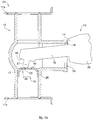
fig. 1a shows a system according to the present invention, in the case where the aperture of the flow passage is increased, in a first operating condition; -
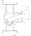
fig. 1b shows the system infig. 1a in a second operating condition; -
fig. 2 shows an example of a system according to the present invention. - To facilitate comprehension, the same reference numbers have been used, where possible, to identify identical common elements in the drawings. It is understood that elements and characteristics of one form of embodiment can conveniently be incorporated into other forms of embodiment without further clarifications.
- With reference to
figs. 1a and1b aheat exchanger 24 consists, by way of example, of two ormore plates - The
plates connector 12 that has two branches connected to theplates free mouth 13 accessible from the outside and that, during use, can be connected to feed/discharge pipes of the heat-carrying fluid or possibly closed by stoppers or valves to release the air. - The
connector 12 can be conformed in various ways, and its conformation has no influence on the invention. - The
free mouth 13 can be personalized in the most various ways, and may or may not have internal and/or external threadings, or other. - The
free mouth 13 is provided with aterminal abutment edge 14. - Inside the
connector 12, in relation to the desired direction of transit of the flow of heat-carrying fluid, achoke element 15 is provided. - Advantageously, but not exclusively, the
choke element 15 is the prefabricated type and is then inserted into theconnector 12. - According to a variant embodiment, it is provided that the
choke element 15 is made directly in theconnector 12. - The
choke element 15 can have different configurations and comprises aninsertion body 25 that, during use, engages against the inside walls of theconnector 12 into which it is inserted. Theinsertion body 25 is provided with one or more fins ormembranes 16 defined by at least a slot orslit 17. Theslot 17 initially determines, in practice, anaperture 26 preset for a guaranteed minimum passage of the heat-carrying fluid through thechoke element 15. - The
fin 16 can be provided with apossible hole 23, with sizes which have no influence on the passage of the fluid. - The
fin 16 can be suitably deformed by means of aregulator device 10 according to the present invention, in order to modify the sizes of the aperture 26 (fig. 1b ) in a predetermined or variable way. - The
regulator device 10 according to the present invention comprises ahandle 20, of various type and sizes to which anarm 19 is associated that has aregulator tooth 21 at the end. - The
handle 20 and thearm 19 have substantially oblong development and are associated with each other, disposed along a common axis. - Some forms of embodiment provide that the
handle 20 and thearm 19 are made in a single body. - Other forms of embodiment provide that the
handle 20 and thearm 19 each have a plate conformation. - The
handle 20 has a section size greater than that of thearm 19 in order to define, together with the latter, ashoulder 18 that during use allows the correct positioning of thearm 19 inside theconnector 12 and resting against theterminal abutment edge 14. - As shown in
fig. 1a , theregulator tooth 21 extends transversely to the longitudinal extension of thearm 19, and its length determines various and specific adjustments of theaperture 26 in thechoke element 15. Theregulator tooth 21 is suitably rounded at its end. - The terminal end of the
arm 19 can be provided with an abutment surface or limitingsurface 22, that cooperates during use with theregulator tooth 21. - The
regulator tooth 21 in this case is disposed substantially orthogonal to thelimiting surface 22. - The
limiting surface 22 can extend on both one side and the other with respect to theregulator tooth 21. - The presence of the
limiting surface 22, coordinated with the length of theregulator tooth 21, determines the degree of deformation of thefin 16 and therefore the sizes of theaperture 26. - During use the
limiting surface 22 rests against the occlusion surface of theinsertion body 25, in practice determining an end-of-travel condition for theregulator tooth 21. - In the form of embodiment in
figs. 1a and1b , the limitingsurface 22 is angled with respect to the axis of longitudinal extension of thearm 19. - One form of embodiment provides that the limiting
surface 22 is inclined by an angle comprised between 3° and 25° with respect to the axis of longitudinal extension of thearm 19. - This solution increases the useful support surface between the limiting
surface 22 and theinsertion body 25. - We shall now describe the functioning of the
device 10 according to the present invention with reference tofigs. 1a and1b . - The
arm 19 is inserted into theconnector 12, through thefree mouth 13, disposing theregulator tooth 21 in correspondence to thefin 16. Theshoulder 18 of thehandle 20 is disposed resting against theterminal edge 14 of theconnector 12. - The
handle 20 is subsequently rotated with fulcrum between theshoulder 18 and theterminal edge 14, and theregulator tooth 21, pressing on thefin 16, deforms the latter determining the desired sizes of theaperture 26. - According to another form of embodiment of the present invention, shown in
fig. 2 , aregulator device 110 is the multifunction type with several positions. - The
regulator device 110 comprises twohandles 20 disposed and associated transversely with respect to each other. - Each of the two ends of the
handles 20 is provided with arespective arm 19. - The ends of the
arms 19 are provided withrespective regulator teeth surfaces - The
regulator teeth fin 16. - One of the ends of the
arms 19 is provided with aregulator tooth 121 that has a hook conformation. - It should be noted that the
hook 121 is conformed depending on the shape and size of thepossible hole 23 provided in thefin 16 of thechoke element 15. Thehook 121 allows to possibly reduce the sizes of theaperture 26 which was previously made by deforming thefin 16 of thechoke element 15. - It is clear that modifications and/or additions of parts may be made to the regulator device as described heretofore, without departing from the field and scope of the present invention as defined in the claims. It is also clear that, although the present invention has been described with reference to some specific examples, a person of skill in the art shall certainly be able to achieve many other equivalent forms of regulator device, having the characteristics as set forth in the claims and hence all coming within the field of protection defined thereby.
Claims (11)
- A system of a regulator device and a choke element (15) that can be inserted in a connection pipe (12) of at least two plates (11a, 11b) of a heat exchanger (24), wherein said device is suitable to regulate the sizes of a flow passage aperture (26) characterized in that said flow passage aperture (26) is defined by at least one membrane (16) of said choke element (15), said membrane (16) having, or not, a transit slot (17) and a possible hole (23), whereas said regulator device comprises a plurality of handles (20) associated with each other and each of which is provided with at least a respective arm (19) each having a regulator tooth (21; 21a, 21b, 21c, 121) extending angled with respect to the longitudinal extension of said arm (19), and in that said regulator tooth (21, 21a, 21b, 21c, 121) on each occasion, has predefined lengths depending on the sizes of the flow passage aperture (26).
- System as in claim 1, characterized in that, together with said arm (19), said handle (20) defines a shoulder (18) that, during use, cooperates with a mouth (13) for access to said connection pipe (12) from the outside.
- System as in claim 2, characterized in that said handle (20) has a section size greater than that of said arm (19) to define said shoulder (18).
- System as in any claim hereinbefore, characterized in that the terminal end of said arm (19) is provided with an abutment surface (22) that cooperates during use with said regulator tooth (21).
- System as in claim 4, characterized in that said regulator tooth (21) is disposed substantially orthogonal with respect to said abutment surface (22).
- System as in claim 4 or 5, characterized in that said abutment surface (22) is angled with respect to the axis of longitudinal extension of the arm (19).
- System as in claim 6, characterized in that said abutment surface (22) is inclined by an angle comprised between 3° and 25° with respect to the axis of longitudinal extension of the arm (19).
- System as in any claim hereinbefore, characterized in that said regulator tooth (121) is conformed as a hook in order to engage in the possible hole (23), to pull said membrane (16), and to reduce the sizes of said aperture (26).
- System as in any claim hereinbefore, characterized in that said handle (20) and said arm (19) are made in a single body.
- System as in any claim hereinbefore, characterized in that said handle (20) and said arm (19) each have a plate conformation.
- System as in any claim hereinbefore, characterized in that said connection pipe (12) is T-shaped.
Applications Claiming Priority (1)
| Application Number | Priority Date | Filing Date | Title |
|---|---|---|---|
| IT000012U ITUD20130012U1 (en) | 2013-03-11 | 2013-03-11 | REGULATOR DEVICE FOR A PARTIALIZATION ELEMENT |
Publications (2)
| Publication Number | Publication Date |
|---|---|
| EP2806219A1 EP2806219A1 (en) | 2014-11-26 |
| EP2806219B1 true EP2806219B1 (en) | 2018-05-09 |
Family
ID=49485069
Family Applications (1)
| Application Number | Title | Priority Date | Filing Date |
|---|---|---|---|
| EP14158338.5A Not-in-force EP2806219B1 (en) | 2013-03-11 | 2014-03-07 | Regulator device for a choke element |
Country Status (2)
| Country | Link |
|---|---|
| EP (1) | EP2806219B1 (en) |
| IT (1) | ITUD20130012U1 (en) |
Family Cites Families (5)
| Publication number | Priority date | Publication date | Assignee | Title |
|---|---|---|---|---|
| US3877514A (en) * | 1972-06-19 | 1975-04-15 | Hayden Trans Cooler Inc | Heat exchanger valve system |
| DE19842233C2 (en) * | 1998-09-15 | 2003-04-30 | Kermi Gmbh | Manually operated angle thermostat |
| ITBO20080004U1 (en) * | 2008-01-10 | 2009-07-11 | Irsap Spa | FLOW DIVERTER FOR COLLETORS |
| DE102010010315B4 (en) * | 2010-03-04 | 2026-04-02 | Hans Berg Gmbh & Co. Kg | Valve connection fitting, valve adapter element, insert element and method for pressing in an insert element |
| DE202012007648U1 (en) * | 2012-08-10 | 2012-09-13 | Hans-Alfred Balg | Radiator valve insert |
-
2013
- 2013-03-11 IT IT000012U patent/ITUD20130012U1/en unknown
-
2014
- 2014-03-07 EP EP14158338.5A patent/EP2806219B1/en not_active Not-in-force
Non-Patent Citations (1)
| Title |
|---|
| None * |
Also Published As
| Publication number | Publication date |
|---|---|
| EP2806219A1 (en) | 2014-11-26 |
| ITUD20130012U1 (en) | 2014-09-12 |
Similar Documents
| Publication | Publication Date | Title |
|---|---|---|
| SA521421966B1 (en) | Fluid exchange devices and related controls, systems, and methods | |
| RU2646208C1 (en) | Method of balancing the heat flow system, system and controller using this method | |
| EP2594886A3 (en) | Heat exchanger and method of manufacturing the same | |
| GB2527682A (en) | Capacity modulating an expansion device of a HVAC system | |
| MY195134A (en) | Heat Exchanger and Refrigeration System Using Same | |
| US6871401B1 (en) | Tool for inserting and removing a corporation stop and method for use thereof | |
| US4653573A (en) | Connecting apparatus for a radiator | |
| FI3791096T3 (en) | Flow control valve assembly and complementary adjustment tool set | |
| EP2806219A1 (en) | Regulator device for a choke element | |
| JP2017525934A (en) | Heat exchanger and air conditioner provided with the same | |
| JP6242500B2 (en) | Fire extinguishing fluid nozzle system for stationary fire extinguishing systems with a throttling ring, and throttling rings for fire extinguishing fluid nozzles and fire extinguishing fluid nozzles | |
| EP3757302A3 (en) | Tap and system for selectively delivering processed and unprocessed liquid | |
| RU182450U1 (en) | REDUCING UNIT | |
| EP4660510A3 (en) | Vacuum adiabatic body and refrigerator | |
| US10494799B2 (en) | Universal hydraulic connection system | |
| CN205090115U (en) | Connecting device and including this connecting device's radiator | |
| EP4004296B1 (en) | Water delivery system | |
| EP2784403A3 (en) | Radiator arrangement | |
| CN101545661B (en) | Water delivery pressure control system and method | |
| CN203273149U (en) | Gas distribution assembly suitable for being installed in kitchen | |
| EP2024690B1 (en) | Connection device for a heating apparatus | |
| CN215372080U (en) | Water flowing device with flow stabilizing valve | |
| CN211574447U (en) | Connector | |
| RU158134U1 (en) | REGULATING DEVICE FOR HEATING SYSTEMS | |
| RU101762U1 (en) | PIPELINE PLUG |
Legal Events
| Date | Code | Title | Description |
|---|---|---|---|
| PUAI | Public reference made under article 153(3) epc to a published international application that has entered the european phase |
Free format text: ORIGINAL CODE: 0009012 |
|
| 17P | Request for examination filed |
Effective date: 20140307 |
|
| AK | Designated contracting states |
Kind code of ref document: A1 Designated state(s): AL AT BE BG CH CY CZ DE DK EE ES FI FR GB GR HR HU IE IS IT LI LT LU LV MC MK MT NL NO PL PT RO RS SE SI SK SM TR |
|
| AX | Request for extension of the european patent |
Extension state: BA ME |
|
| R17P | Request for examination filed (corrected) |
Effective date: 20150525 |
|
| RBV | Designated contracting states (corrected) |
Designated state(s): AL AT BE BG CH CY CZ DE DK EE ES FI FR GB GR HR HU IE IS IT LI LT LU LV MC MK MT NL NO PL PT RO RS SE SI SK SM TR |
|
| RAP1 | Party data changed (applicant data changed or rights of an application transferred) |
Owner name: DL RADIATORS S.R.L. |
|
| GRAP | Despatch of communication of intention to grant a patent |
Free format text: ORIGINAL CODE: EPIDOSNIGR1 |
|
| STAA | Information on the status of an ep patent application or granted ep patent |
Free format text: STATUS: GRANT OF PATENT IS INTENDED |
|
| INTG | Intention to grant announced |
Effective date: 20171130 |
|
| GRAS | Grant fee paid |
Free format text: ORIGINAL CODE: EPIDOSNIGR3 |
|
| GRAA | (expected) grant |
Free format text: ORIGINAL CODE: 0009210 |
|
| STAA | Information on the status of an ep patent application or granted ep patent |
Free format text: STATUS: THE PATENT HAS BEEN GRANTED |
|
| AK | Designated contracting states |
Kind code of ref document: B1 Designated state(s): AL AT BE BG CH CY CZ DE DK EE ES FI FR GB GR HR HU IE IS IT LI LT LU LV MC MK MT NL NO PL PT RO RS SE SI SK SM TR |
|
| REG | Reference to a national code |
Ref country code: GB Ref legal event code: FG4D |
|
| REG | Reference to a national code |
Ref country code: CH Ref legal event code: EP Ref country code: AT Ref legal event code: REF Ref document number: 997933 Country of ref document: AT Kind code of ref document: T Effective date: 20180515 |
|
| REG | Reference to a national code |
Ref country code: IE Ref legal event code: FG4D |
|
| REG | Reference to a national code |
Ref country code: DE Ref legal event code: R096 Ref document number: 602014025104 Country of ref document: DE |
|
| REG | Reference to a national code |
Ref country code: NL Ref legal event code: MP Effective date: 20180509 |
|
| PG25 | Lapsed in a contracting state [announced via postgrant information from national office to epo] |
Ref country code: SE Free format text: LAPSE BECAUSE OF FAILURE TO SUBMIT A TRANSLATION OF THE DESCRIPTION OR TO PAY THE FEE WITHIN THE PRESCRIBED TIME-LIMIT Effective date: 20180509 Ref country code: FI Free format text: LAPSE BECAUSE OF FAILURE TO SUBMIT A TRANSLATION OF THE DESCRIPTION OR TO PAY THE FEE WITHIN THE PRESCRIBED TIME-LIMIT Effective date: 20180509 Ref country code: BG Free format text: LAPSE BECAUSE OF FAILURE TO SUBMIT A TRANSLATION OF THE DESCRIPTION OR TO PAY THE FEE WITHIN THE PRESCRIBED TIME-LIMIT Effective date: 20180809 Ref country code: LT Free format text: LAPSE BECAUSE OF FAILURE TO SUBMIT A TRANSLATION OF THE DESCRIPTION OR TO PAY THE FEE WITHIN THE PRESCRIBED TIME-LIMIT Effective date: 20180509 Ref country code: NO Free format text: LAPSE BECAUSE OF FAILURE TO SUBMIT A TRANSLATION OF THE DESCRIPTION OR TO PAY THE FEE WITHIN THE PRESCRIBED TIME-LIMIT Effective date: 20180809 Ref country code: ES Free format text: LAPSE BECAUSE OF FAILURE TO SUBMIT A TRANSLATION OF THE DESCRIPTION OR TO PAY THE FEE WITHIN THE PRESCRIBED TIME-LIMIT Effective date: 20180509 |
|
| PG25 | Lapsed in a contracting state [announced via postgrant information from national office to epo] |
Ref country code: NL Free format text: LAPSE BECAUSE OF FAILURE TO SUBMIT A TRANSLATION OF THE DESCRIPTION OR TO PAY THE FEE WITHIN THE PRESCRIBED TIME-LIMIT Effective date: 20180509 Ref country code: HR Free format text: LAPSE BECAUSE OF FAILURE TO SUBMIT A TRANSLATION OF THE DESCRIPTION OR TO PAY THE FEE WITHIN THE PRESCRIBED TIME-LIMIT Effective date: 20180509 Ref country code: GR Free format text: LAPSE BECAUSE OF FAILURE TO SUBMIT A TRANSLATION OF THE DESCRIPTION OR TO PAY THE FEE WITHIN THE PRESCRIBED TIME-LIMIT Effective date: 20180810 Ref country code: LV Free format text: LAPSE BECAUSE OF FAILURE TO SUBMIT A TRANSLATION OF THE DESCRIPTION OR TO PAY THE FEE WITHIN THE PRESCRIBED TIME-LIMIT Effective date: 20180509 Ref country code: RS Free format text: LAPSE BECAUSE OF FAILURE TO SUBMIT A TRANSLATION OF THE DESCRIPTION OR TO PAY THE FEE WITHIN THE PRESCRIBED TIME-LIMIT Effective date: 20180509 |
|
| REG | Reference to a national code |
Ref country code: AT Ref legal event code: MK05 Ref document number: 997933 Country of ref document: AT Kind code of ref document: T Effective date: 20180509 |
|
| PG25 | Lapsed in a contracting state [announced via postgrant information from national office to epo] |
Ref country code: RO Free format text: LAPSE BECAUSE OF FAILURE TO SUBMIT A TRANSLATION OF THE DESCRIPTION OR TO PAY THE FEE WITHIN THE PRESCRIBED TIME-LIMIT Effective date: 20180509 Ref country code: EE Free format text: LAPSE BECAUSE OF FAILURE TO SUBMIT A TRANSLATION OF THE DESCRIPTION OR TO PAY THE FEE WITHIN THE PRESCRIBED TIME-LIMIT Effective date: 20180509 Ref country code: CZ Free format text: LAPSE BECAUSE OF FAILURE TO SUBMIT A TRANSLATION OF THE DESCRIPTION OR TO PAY THE FEE WITHIN THE PRESCRIBED TIME-LIMIT Effective date: 20180509 Ref country code: AT Free format text: LAPSE BECAUSE OF FAILURE TO SUBMIT A TRANSLATION OF THE DESCRIPTION OR TO PAY THE FEE WITHIN THE PRESCRIBED TIME-LIMIT Effective date: 20180509 Ref country code: DK Free format text: LAPSE BECAUSE OF FAILURE TO SUBMIT A TRANSLATION OF THE DESCRIPTION OR TO PAY THE FEE WITHIN THE PRESCRIBED TIME-LIMIT Effective date: 20180509 Ref country code: PL Free format text: LAPSE BECAUSE OF FAILURE TO SUBMIT A TRANSLATION OF THE DESCRIPTION OR TO PAY THE FEE WITHIN THE PRESCRIBED TIME-LIMIT Effective date: 20180509 Ref country code: SK Free format text: LAPSE BECAUSE OF FAILURE TO SUBMIT A TRANSLATION OF THE DESCRIPTION OR TO PAY THE FEE WITHIN THE PRESCRIBED TIME-LIMIT Effective date: 20180509 |
|
| REG | Reference to a national code |
Ref country code: DE Ref legal event code: R097 Ref document number: 602014025104 Country of ref document: DE |
|
| PG25 | Lapsed in a contracting state [announced via postgrant information from national office to epo] |
Ref country code: IT Free format text: LAPSE BECAUSE OF FAILURE TO SUBMIT A TRANSLATION OF THE DESCRIPTION OR TO PAY THE FEE WITHIN THE PRESCRIBED TIME-LIMIT Effective date: 20180509 Ref country code: SM Free format text: LAPSE BECAUSE OF FAILURE TO SUBMIT A TRANSLATION OF THE DESCRIPTION OR TO PAY THE FEE WITHIN THE PRESCRIBED TIME-LIMIT Effective date: 20180509 |
|
| PLBE | No opposition filed within time limit |
Free format text: ORIGINAL CODE: 0009261 |
|
| STAA | Information on the status of an ep patent application or granted ep patent |
Free format text: STATUS: NO OPPOSITION FILED WITHIN TIME LIMIT |
|
| 26N | No opposition filed |
Effective date: 20190212 |
|
| PG25 | Lapsed in a contracting state [announced via postgrant information from national office to epo] |
Ref country code: SI Free format text: LAPSE BECAUSE OF FAILURE TO SUBMIT A TRANSLATION OF THE DESCRIPTION OR TO PAY THE FEE WITHIN THE PRESCRIBED TIME-LIMIT Effective date: 20180509 |
|
| PG25 | Lapsed in a contracting state [announced via postgrant information from national office to epo] |
Ref country code: AL Free format text: LAPSE BECAUSE OF FAILURE TO SUBMIT A TRANSLATION OF THE DESCRIPTION OR TO PAY THE FEE WITHIN THE PRESCRIBED TIME-LIMIT Effective date: 20180509 |
|
| PG25 | Lapsed in a contracting state [announced via postgrant information from national office to epo] |
Ref country code: TR Free format text: LAPSE BECAUSE OF FAILURE TO SUBMIT A TRANSLATION OF THE DESCRIPTION OR TO PAY THE FEE WITHIN THE PRESCRIBED TIME-LIMIT Effective date: 20180509 |
|
| PGFP | Annual fee paid to national office [announced via postgrant information from national office to epo] |
Ref country code: DE Payment date: 20200319 Year of fee payment: 7 Ref country code: MC Payment date: 20200327 Year of fee payment: 7 Ref country code: IE Payment date: 20200324 Year of fee payment: 7 Ref country code: GB Payment date: 20200309 Year of fee payment: 7 |
|
| REG | Reference to a national code |
Ref country code: CH Ref legal event code: NV Representative=s name: RAPISARDI INTELLECTUAL PROPERTY SA, CH |
|
| PGFP | Annual fee paid to national office [announced via postgrant information from national office to epo] |
Ref country code: LU Payment date: 20200311 Year of fee payment: 7 Ref country code: BE Payment date: 20200311 Year of fee payment: 7 Ref country code: CH Payment date: 20200312 Year of fee payment: 7 |
|
| PG25 | Lapsed in a contracting state [announced via postgrant information from national office to epo] |
Ref country code: PT Free format text: LAPSE BECAUSE OF FAILURE TO SUBMIT A TRANSLATION OF THE DESCRIPTION OR TO PAY THE FEE WITHIN THE PRESCRIBED TIME-LIMIT Effective date: 20180910 Ref country code: MT Free format text: LAPSE BECAUSE OF NON-PAYMENT OF DUE FEES Effective date: 20190307 |
|
| PGFP | Annual fee paid to national office [announced via postgrant information from national office to epo] |
Ref country code: FR Payment date: 20200310 Year of fee payment: 7 |
|
| PG25 | Lapsed in a contracting state [announced via postgrant information from national office to epo] |
Ref country code: CY Free format text: LAPSE BECAUSE OF FAILURE TO SUBMIT A TRANSLATION OF THE DESCRIPTION OR TO PAY THE FEE WITHIN THE PRESCRIBED TIME-LIMIT Effective date: 20180509 |
|
| PG25 | Lapsed in a contracting state [announced via postgrant information from national office to epo] |
Ref country code: IS Free format text: LAPSE BECAUSE OF FAILURE TO SUBMIT A TRANSLATION OF THE DESCRIPTION OR TO PAY THE FEE WITHIN THE PRESCRIBED TIME-LIMIT Effective date: 20180909 |
|
| PG25 | Lapsed in a contracting state [announced via postgrant information from national office to epo] |
Ref country code: HU Free format text: LAPSE BECAUSE OF FAILURE TO SUBMIT A TRANSLATION OF THE DESCRIPTION OR TO PAY THE FEE WITHIN THE PRESCRIBED TIME-LIMIT; INVALID AB INITIO Effective date: 20140307 |
|
| REG | Reference to a national code |
Ref country code: DE Ref legal event code: R119 Ref document number: 602014025104 Country of ref document: DE |
|
| PG25 | Lapsed in a contracting state [announced via postgrant information from national office to epo] |
Ref country code: MC Free format text: LAPSE BECAUSE OF NON-PAYMENT OF DUE FEES Effective date: 20210331 |
|
| REG | Reference to a national code |
Ref country code: CH Ref legal event code: PL |
|
| GBPC | Gb: european patent ceased through non-payment of renewal fee |
Effective date: 20210307 |
|
| REG | Reference to a national code |
Ref country code: BE Ref legal event code: MM Effective date: 20210331 |
|
| PG25 | Lapsed in a contracting state [announced via postgrant information from national office to epo] |
Ref country code: DE Free format text: LAPSE BECAUSE OF NON-PAYMENT OF DUE FEES Effective date: 20211001 Ref country code: IE Free format text: LAPSE BECAUSE OF NON-PAYMENT OF DUE FEES Effective date: 20210307 Ref country code: FR Free format text: LAPSE BECAUSE OF NON-PAYMENT OF DUE FEES Effective date: 20210331 Ref country code: GB Free format text: LAPSE BECAUSE OF NON-PAYMENT OF DUE FEES Effective date: 20210307 Ref country code: CH Free format text: LAPSE BECAUSE OF NON-PAYMENT OF DUE FEES Effective date: 20210331 Ref country code: LI Free format text: LAPSE BECAUSE OF NON-PAYMENT OF DUE FEES Effective date: 20210331 Ref country code: LU Free format text: LAPSE BECAUSE OF NON-PAYMENT OF DUE FEES Effective date: 20210307 |
|
| PG25 | Lapsed in a contracting state [announced via postgrant information from national office to epo] |
Ref country code: MK Free format text: LAPSE BECAUSE OF FAILURE TO SUBMIT A TRANSLATION OF THE DESCRIPTION OR TO PAY THE FEE WITHIN THE PRESCRIBED TIME-LIMIT Effective date: 20180509 |
|
| PG25 | Lapsed in a contracting state [announced via postgrant information from national office to epo] |
Ref country code: BE Free format text: LAPSE BECAUSE OF NON-PAYMENT OF DUE FEES Effective date: 20210331 |