EP2806099A1 - Alignment of bop stack to facilitate use of a rotating control device - Google Patents
Alignment of bop stack to facilitate use of a rotating control device Download PDFInfo
- Publication number
- EP2806099A1 EP2806099A1 EP20140171890 EP14171890A EP2806099A1 EP 2806099 A1 EP2806099 A1 EP 2806099A1 EP 20140171890 EP20140171890 EP 20140171890 EP 14171890 A EP14171890 A EP 14171890A EP 2806099 A1 EP2806099 A1 EP 2806099A1
- Authority
- EP
- European Patent Office
- Prior art keywords
- axis
- alignment
- alignment device
- flanges
- flange
- Prior art date
- Legal status (The legal status is an assumption and is not a legal conclusion. Google has not performed a legal analysis and makes no representation as to the accuracy of the status listed.)
- Withdrawn
Links
- 238000000034 method Methods 0.000 claims abstract description 53
- 238000005553 drilling Methods 0.000 description 9
- 238000005452 bending Methods 0.000 description 2
- 230000008901 benefit Effects 0.000 description 2
- 238000004519 manufacturing process Methods 0.000 description 2
- 229910000831 Steel Inorganic materials 0.000 description 1
- 238000007792 addition Methods 0.000 description 1
- 230000000712 assembly Effects 0.000 description 1
- 238000000429 assembly Methods 0.000 description 1
- 238000010276 construction Methods 0.000 description 1
- 238000012217 deletion Methods 0.000 description 1
- 230000037430 deletion Effects 0.000 description 1
- 230000001419 dependent effect Effects 0.000 description 1
- 239000012530 fluid Substances 0.000 description 1
- 238000012423 maintenance Methods 0.000 description 1
- 230000013011 mating Effects 0.000 description 1
- 238000012986 modification Methods 0.000 description 1
- 230000004048 modification Effects 0.000 description 1
- 238000012545 processing Methods 0.000 description 1
- 238000007789 sealing Methods 0.000 description 1
- 125000006850 spacer group Chemical group 0.000 description 1
- 239000010959 steel Substances 0.000 description 1
- 238000006467 substitution reaction Methods 0.000 description 1
- 238000012360 testing method Methods 0.000 description 1
Images

Classifications
-
- E—FIXED CONSTRUCTIONS
- E21—EARTH OR ROCK DRILLING; MINING
- E21B—EARTH OR ROCK DRILLING; OBTAINING OIL, GAS, WATER, SOLUBLE OR MELTABLE MATERIALS OR A SLURRY OF MINERALS FROM WELLS
- E21B33/00—Sealing or packing boreholes or wells
- E21B33/02—Surface sealing or packing
- E21B33/03—Well heads; Setting-up thereof
- E21B33/06—Blow-out preventers, i.e. apparatus closing around a drill pipe, e.g. annular blow-out preventers
-
- E—FIXED CONSTRUCTIONS
- E21—EARTH OR ROCK DRILLING; MINING
- E21B—EARTH OR ROCK DRILLING; OBTAINING OIL, GAS, WATER, SOLUBLE OR MELTABLE MATERIALS OR A SLURRY OF MINERALS FROM WELLS
- E21B23/00—Apparatus for displacing, setting, locking, releasing or removing tools, packers or the like in boreholes or wells
-
- E—FIXED CONSTRUCTIONS
- E21—EARTH OR ROCK DRILLING; MINING
- E21B—EARTH OR ROCK DRILLING; OBTAINING OIL, GAS, WATER, SOLUBLE OR MELTABLE MATERIALS OR A SLURRY OF MINERALS FROM WELLS
- E21B33/00—Sealing or packing boreholes or wells
- E21B33/02—Surface sealing or packing
- E21B33/08—Wipers; Oil savers
- E21B33/085—Rotatable packing means, e.g. rotating blow-out preventers
-
- F—MECHANICAL ENGINEERING; LIGHTING; HEATING; WEAPONS; BLASTING
- F16—ENGINEERING ELEMENTS AND UNITS; GENERAL MEASURES FOR PRODUCING AND MAINTAINING EFFECTIVE FUNCTIONING OF MACHINES OR INSTALLATIONS; THERMAL INSULATION IN GENERAL
- F16L—PIPES; JOINTS OR FITTINGS FOR PIPES; SUPPORTS FOR PIPES, CABLES OR PROTECTIVE TUBING; MEANS FOR THERMAL INSULATION IN GENERAL
- F16L23/00—Flanged joints
- F16L23/003—Auxiliary devices
-
- F—MECHANICAL ENGINEERING; LIGHTING; HEATING; WEAPONS; BLASTING
- F16—ENGINEERING ELEMENTS AND UNITS; GENERAL MEASURES FOR PRODUCING AND MAINTAINING EFFECTIVE FUNCTIONING OF MACHINES OR INSTALLATIONS; THERMAL INSULATION IN GENERAL
- F16L—PIPES; JOINTS OR FITTINGS FOR PIPES; SUPPORTS FOR PIPES, CABLES OR PROTECTIVE TUBING; MEANS FOR THERMAL INSULATION IN GENERAL
- F16L23/00—Flanged joints
- F16L23/006—Attachments
-
- F—MECHANICAL ENGINEERING; LIGHTING; HEATING; WEAPONS; BLASTING
- F16—ENGINEERING ELEMENTS AND UNITS; GENERAL MEASURES FOR PRODUCING AND MAINTAINING EFFECTIVE FUNCTIONING OF MACHINES OR INSTALLATIONS; THERMAL INSULATION IN GENERAL
- F16L—PIPES; JOINTS OR FITTINGS FOR PIPES; SUPPORTS FOR PIPES, CABLES OR PROTECTIVE TUBING; MEANS FOR THERMAL INSULATION IN GENERAL
- F16L27/00—Adjustable joints; Joints allowing movement
-
- Y—GENERAL TAGGING OF NEW TECHNOLOGICAL DEVELOPMENTS; GENERAL TAGGING OF CROSS-SECTIONAL TECHNOLOGIES SPANNING OVER SEVERAL SECTIONS OF THE IPC; TECHNICAL SUBJECTS COVERED BY FORMER USPC CROSS-REFERENCE ART COLLECTIONS [XRACs] AND DIGESTS
- Y10—TECHNICAL SUBJECTS COVERED BY FORMER USPC
- Y10T—TECHNICAL SUBJECTS COVERED BY FORMER US CLASSIFICATION
- Y10T29/00—Metal working
- Y10T29/53—Means to assemble or disassemble
- Y10T29/53022—Means to assemble or disassemble with means to test work or product
Definitions
- the present disclosure relates generally to connecting components with flanged connections and, in specific examples described herein, more particularly provides for alignment of a BOP stack to facilitate use of a rotating control device.
- assemblies of components are connected using flanged connections.
- the mating surfaces of flanges in the flanged connections are intended to be oriented in a particular direction relative to the associated components being connected. If, however, the flanges are not suitably oriented, or the intended direction changes, the connected components will not be appropriately aligned with each other, or with other equipment.
- An example of such a system is disclosed in GB 2 340 570 .
- An annular joint is disclosed therein which includes internal and external faces, a plane of symmetry passing through an axis, and includes first and second contact zones contained respectively in first and second planes.
- the first and second planes intersect to form a dihedral having an edge perpendicular to the plane of symmetry, where the dihedral angle is between and degrees.
- the joint may be made of steel, and may have a polygonal, isosceles trapezoidal, rectangular trapezoidal, symmetrical oval, or asymmetrical oval cross section.
- the joint is used to connect two ducting members provided with flanges at each end, so that the longitudinal axes of the ducting members are not aligned.
- the joint may be used in the production of a curved ducting, eg a riser, for connecting an equipment item installed on the sea bed with a drilling platform or oil production platform.
- GB 130 846 also discloses two circular or annular wedges, bored to the inner diameter of a pipe and turned to the outer diameter of the flanges. The user can take the device and, guided by graduations, revolve the two wedges relatively to one another. The device can then be drilled to the flanges and bolted together.
- BOP blowout preventers
- RCD rotating control devices
- a flanged casing bowl is welded to the top of casing at a wellhead.
- the casing bowl allows secure, sealed attachment of blowout preventers and a rotating control device to the casing at the surface during well drilling and completion operations.
- casing bowls are not always welded to the top of the casing so that they are level (i.e., with the top flange surface of the casing bowl perfectly horizontal).
- the BOP's and RCD are bolted to the casing bowl, they are also not level, and any drill string or completion string which passes through the BOP's and RCD tend to rub on the inner surfaces of the BOP's and RCD. This causes damage to the seals and various other internal components of the BOP's and RCD, requiring expensive and time-consuming maintenance for these components.
- the BOP's and RCD are preferably aligned with an opening in a rig floor above the BOP's and RCD. If a rotary table is used in the rig floor, then a longitudinal axis of the BOP's and RCD is preferably axially aligned with the opening in the rotary table. However, a rig can settle during drilling and/or completion operations, and so it may be desirable to re-align the BOP's and RCD with the opening in the rig floor if misalignment does occur.
- one or more alignment devices in the form of wedge-shaped spacers (which are thinner on one side than on an opposite side) are interposed between the casing bowl flange and a flange of the BOP's and RCD assembly. In this way, any deviation of the casing bowl flange from horizontal can be corrected prior to attachment of the BOP's and RCD. Multiple alignment devices may be used, if necessary.
- FIG. 1 Representatively illustrated in FIG. 1 is an alignment system 10 and associated method which can embody principles of the present disclosure.
- a casing bowl 12 has been welded to the top of a casing string 14 at a wellhead.
- a flange 16 of the casing bowl 12 is not horizontal and, thus, is not oriented in a plane orthogonal to a longitudinal axis 18 of the casing string 14.
- a longitudinal axis 24 of the blowout preventer stack and rotating control device does not coincide with the axis 18 of the casing string 14.
- a tubular string 30 such as a drill string, work string, test string, completion string, etc.
- the axis 24 is also not aligned with a longitudinal axis 32 of the tubular string 30 and opening 26, and so the tubular string will rub against the interior of the blowout preventer stack 20 and rotating control device 22 as it is conveyed into and out of the casing string 14, and/or as it is rotated (e.g., using a rotary table 34). This could damage internal features of the blowout preventer stack 20 and rotating control device 22, and/or could prevent effective sealing between the tubular string 30 and the blowout preventer stack and/or rotating control device.
- the blowout preventer stack 20 includes ram-type blowout preventers 36, 38 and an annular blowout preventer 40.
- a lower flange 42 of the lower blowout preventer 38 attaches to the flange 16 of the casing bowl 12.
- the blowout preventers 36, 38, 40 are used to seal off the wellhead and thereby prevent undesired escape of fluids from the well in emergency situations (e.g., to prevent an uncontrolled blowout), or to seal off the annular space about the tubular string 30 in well control situations (e.g., when an excessive kick occurs in drilling operations). Rotation or other manipulation of the tubular string 30 would cease prior to operation of the blowout preventers 36, 38, 40.
- the rotating control device 22 is used to seal off the annular space about the tubular string 30 during drilling operations (i.e., while the tubular string is being rotated and/or lowered into the well to further drill a wellbore, although rotation of the tubular string is not necessary if a mud motor is used to rotate a drill bit on the lower end of the tubular string).
- the rotating control device 22 may be used in managed pressure drilling (such as, in underbalanced drilling, at balance drilling or slightly overbalanced drilling operations). However, it should be understood that use of the rotating control device 22 is not necessary in keeping with the principles of this disclosure.
- the system 10 utilizes one or more alignment devices 44 interposed between the flanges 16, 42 to produce an angular offset which compensates for the misalignment of the axis 24 relative to the axes 18, 32.
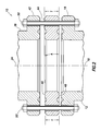
- An enlarged scale schematic cross-sectional view of the flanges 16, 42 and the alignment device 44 is representatively illustrated in FIG. 2 .
- the alignment device 44 has opposing planar flange surfaces 46, 48 which are angled relative to one another, due to the alignment device having a greater thickness T on one side as compared to a thickness t on an opposite side.
- an angular offset A will be produced, thereby aligning the axes 18, 24 and aligning the axis 24 with the axis 32 (not visible in FIG. 2 ).
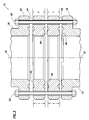
- a single alignment device 44 may not be sufficient to produce a desired angular offset A between the flanges 16, 42, in which case multiple alignment devices may be used.
- An example is representatively illustrated in FIG. 3 .
- the increments of adjustment in the depicted examples is determined by the number of bolts 50 (and associated bolt holes in the flanges 16, 42). For example, if there are twelve bolts 50 (and associated bolt holes) used to clamp the flanges 16, 42 to each other, then the number of increments of adjustment is also twelve, with each increment equaling thirty degrees (360 degrees/12 increments) of relative rotation between the alignment devices 44.
- the maximum angular offset A between the flanges 16, 42 is depicted in FIG. 3 , with the greatest thicknesses T of the alignment devices 44 overlapping each other.
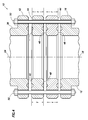
- the minimum angular offset A (zero angular offset) is depicted, with the greatest thickness T of one alignment device 44 overlapping the least thickness t of the other alignment device.
- the configuration of FIG. 4 may not be of use in a particular circumstance, since it produces no angular offset between the flanges 16, 42, but coupled with the configuration of FIG. 3 , it does show the range of adjustability of the angular offset.
- increments of adjustment of the angular offset between the flanges 16, 42 are determined by the number of bolts 50 (and associated bolt holes) in the flanges.
- finer or coarser increments of adjustment could be produced by providing a greater or fewer number of bolt holes in the alignment devices 44.
- a theoretically infinite number of angular offset adjustments could be produced by eliminating the bolt holes in one or all of the alignment devices 44.
- use of the bolt holes in the alignment devices 44 is presently preferred, since they can provide definite known values and increments of angular offsets for a particular configuration, and they help to maintain the alignment devices in position during assembly.
- the use of the alignment device(s) 44 between the flanges 16, 42 can produce a desired angular offset A between the flanges to thereby align components on either side of the flanges and/or to align a component with another item of equipment.
- the angular offset A between the flanges 16, 42 can align the axis 24 with the axes 18, 32, align the blowout preventer stack 20 and blowout preventers 36, 38, 40 thereof with the casing string 14 and/or opening 26 in the rig floor 28, align the rotating control device 22 with the casing string and/or opening in the rig floor, etc.
- Benefits can be derived from the angular offset A even if one of the flanges 16, 42 is not initially misaligned. For example, if the rig settles (thereby misaligning the opening 26 in the rig floor 28 with the axis 24 of the blowout preventer stack 20 and rotating control device 22), the alignment device(s) 44 can be used to restore alignment, without a need to move the rig itself.
- the above disclosure provides to the art a system 10 and associated method in which an angled alignment device 44 is interposed between a casing bowl flange 16 and a flange 42 of a blowout preventer 38 to thereby vertically align the blowout preventer (and associated blowout preventer stack 20 and rotating control device 22).
- the flanges 16, 42 could be provided on other components, and one or more of the components could be aligned with equipment other than a rig floor 28, rotary table 34, opening 26, tubular string 30, etc.
- Adjustment increments may be determined by the number of bolt holes in the flanges 16, 42 and alignment devices 44, or a greater or lesser number of increments may be provided.
- the alignment device(s) 44 may be used between any types of flanges, to thereby axially align any type of components (such as pipes, valves, etc.) on opposite sides of the flanges (i.e., the components on opposite sides of the flanges are axially aligned, but one or both of the flanges may not be axially aligned with those components).
- any type of components such as pipes, valves, etc.
- the components do not have to be related to wells; they could be used in any type of pipelines, processing plants, power plants, etc.
- the alignment device(s) 44 may be used between flanges to align a component associated with one of the flanges with another item of equipment.
- the blowout preventer stack 20 (which is associated with the flange 42) is aligned with the opening 26 in the rig floor 28 (which is not rigidly secured to either of the flanges 16, 42).
- an alignment system 10 which comprises at least one alignment device 44 positioned between two flanges 16, 42, with the alignment device 44 having a greater thickness T on one side of the alignment device 44 than on an opposite side of the alignment device 44.
- the system 10 can include multiple alignment devices 44 positioned between the flanges 16, 42.
- the alignment devices 44 may be displaceable relative to each other to thereby vary an angular offset A of one flange 16 relative to the other flange 42.
- One of the flanges 42 may be part of a blowout preventer 38.
- the alignment device 44 may align an axis 24 of the blowout preventer 38 with an axis 32 of a tubular string 30 extending through a rig floor 28.
- a rotating control device 22 may be connected to the blowout preventer 38.
- the alignment device 44 may align an axis 24 of the rotating control device 22 with an axis 32 of a tubular string 30 extending through a rig floor 28.
- One of the flanges 16 may be part of a casing bowl 12.
- the alignment device 44 may align an axis 24 of a blowout preventer stack 20 and/or a rotating control device 22 with an axis 18 of a casing string 14.
- Also provided by the above disclosure is a method of producing a relative angular offset A between a first flange 16 and a second flange 42.
- the method includes positioning at least one alignment device 44 between the first and second flanges 16, 42; and securing the alignment device 44 between the first and second flanges 16, 42, thereby producing the angular offset A.
- the positioning step may include positioning multiple alignment devices 44 between the first and second flanges 16, 42.
- the method can include displacing a first one of the alignment devices 44 relative to a second one of the alignments devices 44, thereby varying the angular offset.
- Securing the alignment device 44 may include aligning an axis 24 of a blowout preventer stack 20 and/or rotating control device 22 with an axis 18 of a casing string 14.
- the first flange 16 may be part of a casing bowl 12.
- the second flange 42 may be part of a blowout preventer 38.
- Securing the alignment device 44 may include aligning an axis 24 of the blowout preventer 38 with an axis 32 of a tubular string 30 extending through a rig floor 28.
- the method may include connecting a rotating control device 22 to the blowout preventer 36, 38, 40.
- Securing the alignment device 44 may include aligning an axis 24 of the rotating control device 22 with an axis 32 of a tubular string 30 extending through a rig floor 28.
- the above disclosure also provides to the art a method of aligning an axis 24 of a blowout preventer stack 20 with a rig floor 28.
- the method includes positioning at least one alignment device 44 between a first flange 16 and a second flange 42 of the blowout preventer stack 20; and securing the alignment device 44 between the first and second flanges 16, 42, thereby producing an angular offset A of the second flange 42 relative to the first flange 16.
- Securing the alignment device 44 may include aligning the axis 24 of the blowout preventer stack 20 with an axis 32 of a tubular string 30 extending through the rig floor 28.
- the method may include connecting a rotating control device 22 to the blowout preventer stack 20.
- Securing the alignment device 44 may include aligning an axis 24 of the rotating control device 22 with an axis 32 of a tubular string 30 extending through the rig floor 28.
- the positioning step may include positioning multiple alignment devices 44 between the first and second flanges 16, 42.
- the method may include displacing a first one of the alignment devices 44 relative to a second one of the alignments devices 44, thereby varying the angular offset.
- the displacing step may include selecting from among predetermined rotational orientations of the first alignment device 44 relative to the second alignment device 44.
- the first flange 16 may be part of a casing bowl 12.
- Securing the alignment device 44 may include aligning the axis 24 of the blowout preventer stack 20 and/or a rotating control device 22 with an axis 18 of a casing string 14.
Landscapes
- Engineering & Computer Science (AREA)
- General Engineering & Computer Science (AREA)
- Life Sciences & Earth Sciences (AREA)
- Geology (AREA)
- Mining & Mineral Resources (AREA)
- Environmental & Geological Engineering (AREA)
- Fluid Mechanics (AREA)
- General Life Sciences & Earth Sciences (AREA)
- Geochemistry & Mineralogy (AREA)
- Physics & Mathematics (AREA)
- Mechanical Engineering (AREA)
- Joints Allowing Movement (AREA)
- Earth Drilling (AREA)
- Wind Motors (AREA)
Abstract
Description
- The present disclosure relates generally to connecting components with flanged connections and, in specific examples described herein, more particularly provides for alignment of a BOP stack to facilitate use of a rotating control device.
- In various industries, assemblies of components are connected using flanged connections. Typically, the mating surfaces of flanges in the flanged connections are intended to be oriented in a particular direction relative to the associated components being connected. If, however, the flanges are not suitably oriented, or the intended direction changes, the connected components will not be appropriately aligned with each other, or with other equipment.
- An example of such a system is disclosed in
GB 2 340 570 -
GB 130 846 - It will be appreciated that improvements are needed in the art of aligning components connected with flanged connections.
-
-
FIG. 1 is a schematic elevational view of a system and associated method embodying principles of the present disclosure. -
FIG. 2 is an enlarged scale schematic cross-sectional view of flanges and an alignment device as used in the system and method. -
FIG. 3 is a schematic cross-sectional view of another configuration of the flanges and multiple alignment devices as used in the system and method. -
FIG. 4 is a schematic cross-sectional view of yet another configuration of the flanges and multiple alignment devices as used in the system and method. - According to the present invention there is provided a method of aligning an axis of a blowout preventer stack with a rig floor as defined in the appended claim 1.
- Further preferable features of the method of the present invention are defined in the appended dependent claims 2 to 7.
- This disclosure relates to alignment of equipment wherein components are connected using flanges. In specific examples described below, a system and method are provided for alignment of blowout preventers (BOP's), rotating control devices (RCD's, also known as rotating control heads and rotating blowout preventers) with a rig floor and/or a casing string. However, the principles of this disclosure are not limited to only these examples.
- In conventional well construction practice, a flanged casing bowl is welded to the top of casing at a wellhead. The casing bowl allows secure, sealed attachment of blowout preventers and a rotating control device to the casing at the surface during well drilling and completion operations.
- Unfortunately, casing bowls are not always welded to the top of the casing so that they are level (i.e., with the top flange surface of the casing bowl perfectly horizontal). Thus, when the BOP's and RCD are bolted to the casing bowl, they are also not level, and any drill string or completion string which passes through the BOP's and RCD tend to rub on the inner surfaces of the BOP's and RCD. This causes damage to the seals and various other internal components of the BOP's and RCD, requiring expensive and time-consuming maintenance for these components.
- The BOP's and RCD are preferably aligned with an opening in a rig floor above the BOP's and RCD. If a rotary table is used in the rig floor, then a longitudinal axis of the BOP's and RCD is preferably axially aligned with the opening in the rotary table. However, a rig can settle during drilling and/or completion operations, and so it may be desirable to re-align the BOP's and RCD with the opening in the rig floor if misalignment does occur.
- In the examples described below, one or more alignment devices in the form of wedge-shaped spacers (which are thinner on one side than on an opposite side) are interposed between the casing bowl flange and a flange of the BOP's and RCD assembly. In this way, any deviation of the casing bowl flange from horizontal can be corrected prior to attachment of the BOP's and RCD. Multiple alignment devices may be used, if necessary.
- Representatively illustrated in
FIG. 1 is analignment system 10 and associated method which can embody principles of the present disclosure. In thesystem 10, acasing bowl 12 has been welded to the top of acasing string 14 at a wellhead. Unfortunately, aflange 16 of thecasing bowl 12 is not horizontal and, thus, is not oriented in a plane orthogonal to alongitudinal axis 18 of thecasing string 14. - As a result, when a blowout preventer stack 20 and a rotating
control device 22 are connected to thecasing bowl 12, alongitudinal axis 24 of the blowout preventer stack and rotating control device does not coincide with theaxis 18 of thecasing string 14. Another result is that theaxis 24 is not aligned with anopening 26 in arig floor 28 through which a tubular string 30 (such as a drill string, work string, test string, completion string, etc.) extends. - The
axis 24 is also not aligned with alongitudinal axis 32 of thetubular string 30 and opening 26, and so the tubular string will rub against the interior of theblowout preventer stack 20 and rotatingcontrol device 22 as it is conveyed into and out of thecasing string 14, and/or as it is rotated (e.g., using a rotary table 34). This could damage internal features of theblowout preventer stack 20 and rotatingcontrol device 22, and/or could prevent effective sealing between thetubular string 30 and the blowout preventer stack and/or rotating control device. - As depicted in
FIG. 1 , theblowout preventer stack 20 includes ram-type blowout preventers annular blowout preventer 40. Alower flange 42 of thelower blowout preventer 38 attaches to theflange 16 of thecasing bowl 12. Theblowout preventers tubular string 30 in well control situations (e.g., when an excessive kick occurs in drilling operations). Rotation or other manipulation of thetubular string 30 would cease prior to operation of theblowout preventers - In contrast, the
rotating control device 22 is used to seal off the annular space about thetubular string 30 during drilling operations (i.e., while the tubular string is being rotated and/or lowered into the well to further drill a wellbore, although rotation of the tubular string is not necessary if a mud motor is used to rotate a drill bit on the lower end of the tubular string). The rotatingcontrol device 22 may be used in managed pressure drilling (such as, in underbalanced drilling, at balance drilling or slightly overbalanced drilling operations). However, it should be understood that use of the rotatingcontrol device 22 is not necessary in keeping with the principles of this disclosure. - To correct the misalignment of the
axis 24 relative to theaxes 18, 32 (and the associated misalignment of theblowout preventer stack 20 and rotatingcontrol device 22 with thecasing string 14, rig floor opening 26 and tubular string 30), thesystem 10 utilizes one ormore alignment devices 44 interposed between theflanges axis 24 relative to theaxes flanges alignment device 44 is representatively illustrated inFIG. 2 . - Note that the
alignment device 44 has opposingplanar flange surfaces alignment device 44 is clamped between theflanges 16, 42 (such as, by tightening bolts 50), an angular offset A will be produced, thereby aligning theaxes axis 24 with the axis 32 (not visible inFIG. 2 ). - In some circumstances, a
single alignment device 44 may not be sufficient to produce a desired angular offset A between theflanges FIG. 3 . - Another advantage derived from use of
multiple alignment devices 44 is that the angular offset A produced can be varied by rotating one of the alignment devices relative to another alignment device. The increments of adjustment in the depicted examples is determined by the number of bolts 50 (and associated bolt holes in theflanges 16, 42). For example, if there are twelve bolts 50 (and associated bolt holes) used to clamp theflanges alignment devices 44. - The maximum angular offset A between the
flanges FIG. 3 , with the greatest thicknesses T of thealignment devices 44 overlapping each other. InFIG. 4 , the minimum angular offset A (zero angular offset) is depicted, with the greatest thickness T of onealignment device 44 overlapping the least thickness t of the other alignment device. The configuration ofFIG. 4 may not be of use in a particular circumstance, since it produces no angular offset between theflanges FIG. 3 , it does show the range of adjustability of the angular offset. - Note that it is not necessary in keeping with the principles of this disclosure for the increments of adjustment of the angular offset between the
flanges alignment devices 44. - As another example, a theoretically infinite number of angular offset adjustments could be produced by eliminating the bolt holes in one or all of the
alignment devices 44. However, use of the bolt holes in thealignment devices 44 is presently preferred, since they can provide definite known values and increments of angular offsets for a particular configuration, and they help to maintain the alignment devices in position during assembly. - Since the
bolts 50 could be subject to large bending stresses due to the angular offset between theflanges U.S. Patent No. 7144049 may be used on the bolts to prevent such bending stresses. - It may now be fully appreciated that the use of the alignment device(s) 44 between the
flanges flanges axis 24 with theaxes blowout preventer stack 20 andblowout preventers casing string 14 and/oropening 26 in therig floor 28, align therotating control device 22 with the casing string and/or opening in the rig floor, etc. - Benefits can be derived from the angular offset A even if one of the
flanges opening 26 in therig floor 28 with theaxis 24 of theblowout preventer stack 20 and rotating control device 22), the alignment device(s) 44 can be used to restore alignment, without a need to move the rig itself. - Thus, in one example, the above disclosure provides to the art a
system 10 and associated method in which anangled alignment device 44 is interposed between acasing bowl flange 16 and aflange 42 of ablowout preventer 38 to thereby vertically align the blowout preventer (and associatedblowout preventer stack 20 and rotating control device 22). In other examples, theflanges rig floor 28, rotary table 34, opening 26,tubular string 30, etc. - The above disclosure also provides to the art a manner of using multiple angled
alignment devices 44 betweenflanges flanges alignment devices 44, or a greater or lesser number of increments may be provided. - The alignment device(s) 44 may be used between any types of flanges, to thereby axially align any type of components (such as pipes, valves, etc.) on opposite sides of the flanges (i.e., the components on opposite sides of the flanges are axially aligned, but one or both of the flanges may not be axially aligned with those components).
- In this aspect, the components do not have to be related to wells; they could be used in any type of pipelines, processing plants, power plants, etc.
- In another aspect, the alignment device(s) 44 may be used between flanges to align a component associated with one of the flanges with another item of equipment. Thus, in the examples described above, the blowout preventer stack 20 (which is associated with the flange 42) is aligned with the
opening 26 in the rig floor 28 (which is not rigidly secured to either of theflanges 16, 42). - More particularly, the above disclosure provides to the art an
alignment system 10 which comprises at least onealignment device 44 positioned between twoflanges alignment device 44 having a greater thickness T on one side of thealignment device 44 than on an opposite side of thealignment device 44. - The
system 10 can includemultiple alignment devices 44 positioned between theflanges - The
alignment devices 44 may be displaceable relative to each other to thereby vary an angular offset A of oneflange 16 relative to theother flange 42. - One of the
flanges 42 may be part of ablowout preventer 38. Thealignment device 44 may align anaxis 24 of theblowout preventer 38 with anaxis 32 of atubular string 30 extending through arig floor 28. - A
rotating control device 22 may be connected to theblowout preventer 38. Thealignment device 44 may align anaxis 24 of therotating control device 22 with anaxis 32 of atubular string 30 extending through arig floor 28. - One of the
flanges 16 may be part of acasing bowl 12. - The
alignment device 44 may align anaxis 24 of ablowout preventer stack 20 and/or arotating control device 22 with anaxis 18 of acasing string 14. - Also provided by the above disclosure is a method of producing a relative angular offset A between a
first flange 16 and asecond flange 42. The method includes positioning at least onealignment device 44 between the first andsecond flanges alignment device 44 between the first andsecond flanges - The positioning step may include positioning
multiple alignment devices 44 between the first andsecond flanges alignment devices 44 relative to a second one of thealignments devices 44, thereby varying the angular offset. - Securing the
alignment device 44 may include aligning anaxis 24 of ablowout preventer stack 20 and/orrotating control device 22 with anaxis 18 of acasing string 14. - The
first flange 16 may be part of acasing bowl 12. Thesecond flange 42 may be part of ablowout preventer 38. - Securing the
alignment device 44 may include aligning anaxis 24 of theblowout preventer 38 with anaxis 32 of atubular string 30 extending through arig floor 28. - The method may include connecting a
rotating control device 22 to theblowout preventer - Securing the
alignment device 44 may include aligning anaxis 24 of therotating control device 22 with anaxis 32 of atubular string 30 extending through arig floor 28. - The above disclosure also provides to the art a method of aligning an
axis 24 of ablowout preventer stack 20 with arig floor 28. The method includes positioning at least onealignment device 44 between afirst flange 16 and asecond flange 42 of theblowout preventer stack 20; and securing thealignment device 44 between the first andsecond flanges second flange 42 relative to thefirst flange 16. - Securing the
alignment device 44 may include aligning theaxis 24 of theblowout preventer stack 20 with anaxis 32 of atubular string 30 extending through therig floor 28. - The method may include connecting a
rotating control device 22 to theblowout preventer stack 20. Securing thealignment device 44 may include aligning anaxis 24 of therotating control device 22 with anaxis 32 of atubular string 30 extending through therig floor 28. - The positioning step may include positioning
multiple alignment devices 44 between the first andsecond flanges alignment devices 44 relative to a second one of thealignments devices 44, thereby varying the angular offset. The displacing step may include selecting from among predetermined rotational orientations of thefirst alignment device 44 relative to thesecond alignment device 44. - The
first flange 16 may be part of acasing bowl 12. - Securing the
alignment device 44 may include aligning theaxis 24 of theblowout preventer stack 20 and/or arotating control device 22 with anaxis 18 of acasing string 14. - It is to be understood that the various embodiments of the present disclosure described herein may be utilized in various orientations, such as inclined, inverted, horizontal, vertical, etc., and in various configurations, without departing from the principles of the present disclosure. The embodiments are described merely as examples of useful applications of the principles of the disclosure, which are not limited to any specific details of these embodiments.
- In the above description of the representative embodiments of the disclosure, directional terms, such as "above", "below", "upper", "lower", etc., are used merely for convenience in referring to the accompanying drawings.
- Of course, a person skilled in the art would, upon a careful consideration of the above description of representative embodiments of the disclosure, readily appreciate that many modifications, additions, substitutions, deletions, and other changes may be made to the specific embodiments, and such changes are contemplated by the principles of the present disclosure. Accordingly, the foregoing detailed description is to be clearly understood as being given by way of illustration and example only, the spirit and scope of the present invention being limited solely by the appended claims and their equivalents.
- Apparatus and methods may also be provided as recited in the following numbered statements:
- 1. An alignment system, comprising:
- at least one alignment device positioned between two flanges, the alignment device having a greater thickness on one side of the alignment device than on an opposite side of the alignment device.
- 2. The system of 1, wherein the system comprises multiple alignment devices positioned between the flanges.
- 3. The system of 2, wherein the alignment devices are displaceable relative to each other to thereby vary an angular offset of one flange relative to the other flange.
- 4. The system of 1, wherein one of the flanges is part of a blowout preventer.
- 5. The system of 4, wherein the alignment device aligns an axis of the blowout preventer with an axis of a tubular string extending through a rig floor.
- 6. The system of 4, wherein a rotating control device is connected to the blowout preventer.
- 7. The system of 6, wherein the alignment device aligns an axis of the rotating control device with an axis of a tubular string extending through a rig floor.
- 8. The system of 1, wherein one of the flanges is part of a casing bowl.
- 9. The system of 1, wherein the alignment device aligns an axis of a blowout preventer stack with an axis of a casing string.
- 10. The system of 1, wherein the alignment device aligns an axis of a rotating control device with an axis of a casing string.
- 11. A method of producing a relative angular offset between a first flange and a second flange, the method comprising:
- positioning at least one alignment device between the first and second flanges; and
- securing the alignment device between the first and second flanges, thereby producing the angular offset.
- 12. The method of 11, wherein positioning at least one alignment device comprises positioning multiple alignment devices between the first and second flanges.
- 13. The method of 12, further comprising displacing a first one of the alignment devices relative to a second one of the alignments devices, thereby varying the angular offset.
- 14. The method of 11, wherein the first flange is part of a casing bowl.
- 15. The method of 11, wherein securing the alignment device further comprises aligning an axis of a blowout preventer stack with an axis of a casing string.
- 16. The method of 11, wherein securing the alignment device further comprises aligning an axis of a rotating control device with an axis of a casing string.
- 17. The method of 11, wherein the second flange is part of a blowout preventer.
- 18. The method of 17, wherein securing the alignment device further comprises aligning an axis of the blowout preventer with an axis of a tubular string extending through a rig floor.
- 19. The method of 17, further comprising connecting a rotating control device to the blowout preventer.
- 20. The method of 19, wherein securing the alignment device further comprises aligning an axis of the rotating control device with an axis of a tubular string extending through a rig floor.
- 21. A method of aligning an axis of a blowout preventer stack with a rig floor, the method comprising:
- positioning at least one alignment device between a first flange, and a second flange of the blowout preventer stack; and
- securing the alignment device between the first and second flanges, thereby producing an angular offset of the second flange relative to the first flange.
- 22. The method of 21, wherein securing the alignment device further comprises aligning the axis of the blowout preventer stack with an axis of a tubular string extending through the rig floor.
- 23. The method of 21, further comprising connecting a rotating control device to the blowout preventer stack.
- 24. The method of 23, wherein securing the alignment device further comprises aligning an axis of the rotating control device with an axis of a tubular string extending through the rig floor.
- 25. The method of 21, wherein positioning at least one alignment device comprises positioning multiple alignment devices between the first and second flanges.
- 26. The method of 25, further comprising displacing a first one of the alignment devices relative to a second one of the alignments devices, thereby varying the angular offset.
- 27. The method of 26, wherein displacing a first one of the alignment devices relative to a second one of the alignment devices further comprises selecting from among predetermined rotational orientations of the first alignment device relative to the second alignment device.
- 28. The method of 21, wherein the first flange is part of a casing bowl.
- 29. The method of 21, wherein securing the alignment device further comprises aligning the axis of the blowout preventer stack with an axis of a casing string.
- 30. The method of 21, wherein securing the alignment device further comprises aligning an axis of a rotating control device with an axis of a casing string.
Claims (20)
- An alignment system, comprising:at least one alignment device positioned between two flanges, the alignment device having a greater thickness on one side of the alignment device than on an opposite side of the alignment device.
- The system of claim 1, wherein the system comprises multiple alignment devices positioned between the flanges.
- The system of claim 2, wherein the alignment devices are displaceable relative to each other to thereby vary an angular offset of one flange relative to the other flange.
- The system of claim 1, wherein one of the flanges is part of a blowout preventer.
- The system of claim 4, wherein the alignment device aligns an axis of the blowout preventer with an axis of a tubular string extending through a rig floor.
- The system of claim 4, wherein a rotating control device is connected to the blowout preventer.
- The system of claim 6, wherein the alignment device aligns an axis of the rotating control device with an axis of a tubular string extending through a rig floor.
- The system of claim 1, wherein one of the flanges is part of a casing bowl.
- The system of claim 1, wherein the alignment device aligns an axis of a blowout preventer stack with an axis of a casing string.
- The system of claim 1, wherein the alignment device aligns an axis of a rotating control device with an axis of a casing string.
- A method of producing a relative angular offset between a first flange and a second flange, the method comprising:positioning at least one alignment device between the first and second flanges; andsecuring the alignment device between the first and second flanges, thereby producing the angular offset.
- The method of claim 11, wherein positioning at least one alignment device comprises positioning multiple alignment devices between the first and second flanges.
- The method of claim 12, further comprising displacing a first one of the alignment devices relative to a second one of the alignments devices, thereby varying the angular offset.
- The method of claim 11, wherein the first flange is part of a casing bowl.
- The method of claim 11, wherein securing the alignment device further comprises aligning an axis of a blowout preventer stack with an axis of a casing string.
- The method of claim 11, wherein securing the alignment device further comprises aligning an axis of a rotating control device with an axis of a casing string.
- The method of claim 11, wherein the second flange is part of a blowout preventer.
- The method of claim 17, wherein securing the alignment device further comprises aligning an axis of the blowout preventer with an axis of a tubular string extending through a rig floor.
- The method of claim 17, further comprising connecting a rotating control device to the blowout preventer.
- The method of claim 19, wherein securing the alignment device further comprises aligning an axis of the rotating control device with an axis of a tubular string extending through a rig floor.
Priority Applications (1)
| Application Number | Priority Date | Filing Date | Title |
|---|---|---|---|
| EP20140171890 EP2806099A1 (en) | 2010-01-08 | 2010-01-08 | Alignment of bop stack to facilitate use of a rotating control device |
Applications Claiming Priority (3)
| Application Number | Priority Date | Filing Date | Title |
|---|---|---|---|
| EP20140171890 EP2806099A1 (en) | 2010-01-08 | 2010-01-08 | Alignment of bop stack to facilitate use of a rotating control device |
| PCT/US2010/020410 WO2011084159A1 (en) | 2010-01-08 | 2010-01-08 | Alignment of bop stack |
| EP10700143.0A EP2521836B1 (en) | 2010-01-08 | 2010-01-08 | Alignment of a bop stack |
Related Parent Applications (2)
| Application Number | Title | Priority Date | Filing Date |
|---|---|---|---|
| EP10700143.0A Division-Into EP2521836B1 (en) | 2010-01-08 | 2010-01-08 | Alignment of a bop stack |
| EP10700143.0A Division EP2521836B1 (en) | 2010-01-08 | 2010-01-08 | Alignment of a bop stack |
Publications (1)
| Publication Number | Publication Date |
|---|---|
| EP2806099A1 true EP2806099A1 (en) | 2014-11-26 |
Family
ID=42315609
Family Applications (2)
| Application Number | Title | Priority Date | Filing Date |
|---|---|---|---|
| EP10700143.0A Not-in-force EP2521836B1 (en) | 2010-01-08 | 2010-01-08 | Alignment of a bop stack |
| EP20140171890 Withdrawn EP2806099A1 (en) | 2010-01-08 | 2010-01-08 | Alignment of bop stack to facilitate use of a rotating control device |
Family Applications Before (1)
| Application Number | Title | Priority Date | Filing Date |
|---|---|---|---|
| EP10700143.0A Not-in-force EP2521836B1 (en) | 2010-01-08 | 2010-01-08 | Alignment of a bop stack |
Country Status (5)
| Country | Link |
|---|---|
| US (2) | US8109337B2 (en) |
| EP (2) | EP2521836B1 (en) |
| AU (1) | AU2010340372B2 (en) |
| BR (1) | BR112012016748A2 (en) |
| WO (1) | WO2011084159A1 (en) |
Families Citing this family (21)
| Publication number | Priority date | Publication date | Assignee | Title |
|---|---|---|---|---|
| US8479829B2 (en) | 2010-01-08 | 2013-07-09 | Halliburton Energy Services, Inc. | Alignment of BOP stack to facilitate use of a rotating control device |
| WO2011084159A1 (en) | 2010-01-08 | 2011-07-14 | Halliburton Energy Services, Inc. | Alignment of bop stack |
| BR112014008705A2 (en) * | 2011-10-14 | 2017-04-25 | Halliburton Energy Services Inc | alignment system |
| US9828817B2 (en) | 2012-09-06 | 2017-11-28 | Reform Energy Services Corp. | Latching assembly |
| MY181705A (en) | 2012-09-06 | 2021-01-04 | Reform Energy Services Corp | Latching assembly |
| BR112015033166B1 (en) * | 2013-05-20 | 2019-01-02 | Franks Int Llc | tubular driving system and method and apparatus for longitudinally moving a tubular |
| US9216495B2 (en) * | 2013-07-09 | 2015-12-22 | General Electric Company | Spacer |
| US9074447B1 (en) | 2014-01-15 | 2015-07-07 | Trendsetter Engineering, Inc. | Method and system for protecting wellhead integrity |
| GB2524790B (en) * | 2014-04-02 | 2018-02-07 | Schlumberger Holdings | Aligning borehole drilling equipment |
| GB2524789B (en) | 2014-04-02 | 2019-01-02 | Schlumberger Holdings | Methods of monitoring the condition of a sealing element of a rotating control device |
| US10435980B2 (en) | 2015-09-10 | 2019-10-08 | Halliburton Energy Services, Inc. | Integrated rotating control device and gas handling system for a marine drilling system |
| WO2017136948A1 (en) | 2016-02-10 | 2017-08-17 | Western Oiltools Ltd. | Anti-extrusion seal arrangement and ram-style blowout preventer |
| CN109415928B (en) | 2016-05-02 | 2021-10-08 | 斯伦贝谢技术有限公司 | BOP with wide flange body |
| GB2553753B (en) * | 2016-07-25 | 2021-06-16 | A&S Global Ltd | Clamp arrangement |
| BR112019001538B1 (en) | 2016-07-26 | 2023-05-09 | Dreco Energy Services Ulc | METHOD AND APPARATUS FOR REVERSIBLY MODIFYING A PRODUCTION WELL HEAD ASSEMBLY IN A WELL BORE SUBJECT TO INCREASED PRESSURES FROM UNDERGROUND FRACTURING OPERATIONS ADJACENT TO THE WELL HEAD ASSEMBLY |
| CA3049697C (en) | 2017-01-16 | 2023-09-05 | Dreco Energy Services Ulc | Multifunction blowout preventer |
| US11408232B2 (en) | 2017-02-23 | 2022-08-09 | Jason A Hatfield | Skid assembly for transporting, installing and removing blowout preventers |
| USD827972S1 (en) | 2017-02-23 | 2018-09-04 | Jason A Hatfield | Transport and positioning skid |
| US10941628B2 (en) * | 2017-09-25 | 2021-03-09 | Dreco Energy Services Ulc | Adjustable blowout preventer and methods of use |
| US11473377B2 (en) | 2019-04-12 | 2022-10-18 | NTDrill Holdings, LLC | Rotating control device with flexible sleeve |
| CN118997661B (en) * | 2024-10-25 | 2025-02-07 | 陕西太合智能钻探有限公司 | Ground and underground integrated thousand-meter directional drilling rig and drilling method |
Citations (17)
| Publication number | Priority date | Publication date | Assignee | Title |
|---|---|---|---|---|
| GB130846A (en) | 1918-10-10 | 1919-08-14 | Alfred Edward Shackleford | Improvements in or relating to Valves. |
| GB130856A (en) * | 1918-11-01 | 1919-08-14 | Percy Sheldon | Improvements in or relating to Means for Correcting Flange Adjustment in Piping and the like. |
| GB643028A (en) * | 1946-01-26 | 1950-09-15 | Standard Telephones Cables Ltd | Electron discharge tube construction |
| GB816559A (en) * | 1957-10-25 | 1959-07-15 | Hans Ziller | Wedge ring for pipe lines |
| US2963090A (en) * | 1958-12-15 | 1960-12-06 | Jersey Prod Res Co | Aligning means for well equipment |
| US4037680A (en) * | 1975-04-23 | 1977-07-26 | Grove Clinton E | Apparatus for adjusting camber |
| US4195862A (en) * | 1978-05-01 | 1980-04-01 | Shim-A-Line, Inc. | Camber adjusting shim arrangement |
| CA1226128A (en) * | 1983-03-28 | 1987-09-01 | Robert D. Johnson | Shim and method for adjusting wheel alignment |
| US4867472A (en) * | 1986-06-19 | 1989-09-19 | Ward Arlen T | Wheel steering axis inclination, caster, and camber adjustment assembly |
| GB2247723A (en) * | 1990-09-01 | 1992-03-11 | Pfaudler Werke Gmbh | Gasket to be arranged between two enameled flanges |
| DE29901351U1 (en) * | 1999-01-27 | 1999-04-29 | Kroll & Ziller KG, 40721 Hilden | Adjustable wedge ring |
| US5918707A (en) * | 1997-01-24 | 1999-07-06 | Accu Systems, Inc. | Method and apparatus for correcting brake rotor runout |
| GB2340570A (en) | 1998-07-30 | 2000-02-23 | Elf Exploration Prod | Annular joint |
| US7144049B2 (en) | 2004-05-04 | 2006-12-05 | United Technologies Corporation | Spherical flange assembly |
| US20070114039A1 (en) * | 2005-11-21 | 2007-05-24 | Tejas Research And Engineering, Lp | Rotatable flange adapter |
| CN101598253A (en) * | 2009-06-17 | 2009-12-09 | 叶尔肯·拜山 | Turning gasket for flange connection |
| WO2010071627A1 (en) * | 2008-12-15 | 2010-06-24 | Michelin Recherche Et Technique, S.A. | Method and apparatus for adjusting axle alignment |
Family Cites Families (22)
| Publication number | Priority date | Publication date | Assignee | Title |
|---|---|---|---|---|
| US2846013A (en) * | 1957-01-31 | 1958-08-05 | Melvin C Davis | Alignment fitting for well tubing heads |
| US3095927A (en) * | 1960-11-25 | 1963-07-02 | Mcevoy Co | Flange-connected well head apparatus |
| US3915424A (en) | 1973-01-26 | 1975-10-28 | Hydril Co | Blowout preventer with variable inside diameter |
| US4215747A (en) * | 1978-06-05 | 1980-08-05 | Cameron Iron Works, Inc. | Blowout preventer with tubing aligning apparatus |
| US4574881A (en) | 1985-02-12 | 1986-03-11 | Bednarz James W | Split nut in blowout preventer |
| DE3508732A1 (en) | 1985-03-12 | 1986-09-25 | M A N Nutzfahrzeuge GmbH, 8000 München | FLUID-TIGHT LINE CONNECTION |
| US4886121A (en) | 1988-02-29 | 1989-12-12 | Seaboard-Arval Corporation | Universal flexbowl wellhead and well completion method |
| AT394257B (en) | 1990-02-06 | 1992-02-25 | Schwarz Walter | MOLDED AND MATERIAL-CLOSE, PARTICULARLY ELECTRICALLY INSULATING PIPE CONNECTION |
| US5082050A (en) | 1990-05-29 | 1992-01-21 | Solar Turbines Incorporated | Thermal restraint system for a circular heat exchanger |
| US5065816A (en) | 1990-05-29 | 1991-11-19 | Solar Turbines Incorporated | Sealing system for a circular heat exchanger |
| US5427178A (en) | 1994-02-17 | 1995-06-27 | Rodec Tool Company Inc. | Tubing rotator and hanger |
| US6089526A (en) | 1997-05-01 | 2000-07-18 | Stewart & Stevenson Services, Inc. | Ram type blowout preventor |
| US5944110A (en) | 1997-09-11 | 1999-08-31 | Cooper Cameron Corporation | Variable bore ram packer for a ram type blowout preventer |
| EP1762696A3 (en) * | 1999-03-02 | 2016-07-20 | Weatherford Technology Holdings, LLC | Iinternal riser rotating control head |
| US20040046391A1 (en) | 2000-01-14 | 2004-03-11 | Vasudeva Kailash C. | Exhaust system flanges |
| US7448444B2 (en) | 2002-04-10 | 2008-11-11 | Thomson Michael A | Tubing saver rotator and method for using same |
| EP1508002B1 (en) | 2002-05-15 | 2008-07-23 | Imperial Sheet Metal Ltd. | Connection adapter for conduits and ventilation units |
| US7198303B2 (en) | 2003-03-31 | 2007-04-03 | Metex Mfg. Corporation | Exhaust pipe joint and seal |
| US7040411B2 (en) * | 2003-05-02 | 2006-05-09 | National-Oilwell, L.P. | BOP handling system |
| US7380590B2 (en) * | 2004-08-19 | 2008-06-03 | Sunstone Corporation | Rotating pressure control head |
| US7389820B2 (en) | 2005-11-30 | 2008-06-24 | Schlumberger Technology Corporation | Blowout preventer positioning system |
| WO2011084159A1 (en) | 2010-01-08 | 2011-07-14 | Halliburton Energy Services, Inc. | Alignment of bop stack |
-
2010
- 2010-01-08 WO PCT/US2010/020410 patent/WO2011084159A1/en not_active Ceased
- 2010-01-08 AU AU2010340372A patent/AU2010340372B2/en not_active Ceased
- 2010-01-08 EP EP10700143.0A patent/EP2521836B1/en not_active Not-in-force
- 2010-01-08 BR BR112012016748A patent/BR112012016748A2/en not_active IP Right Cessation
- 2010-01-08 EP EP20140171890 patent/EP2806099A1/en not_active Withdrawn
- 2010-12-11 US US12/965,844 patent/US8109337B2/en not_active Expired - Fee Related
-
2011
- 2011-12-30 US US13/341,297 patent/US8261840B2/en not_active Expired - Fee Related
Patent Citations (17)
| Publication number | Priority date | Publication date | Assignee | Title |
|---|---|---|---|---|
| GB130846A (en) | 1918-10-10 | 1919-08-14 | Alfred Edward Shackleford | Improvements in or relating to Valves. |
| GB130856A (en) * | 1918-11-01 | 1919-08-14 | Percy Sheldon | Improvements in or relating to Means for Correcting Flange Adjustment in Piping and the like. |
| GB643028A (en) * | 1946-01-26 | 1950-09-15 | Standard Telephones Cables Ltd | Electron discharge tube construction |
| GB816559A (en) * | 1957-10-25 | 1959-07-15 | Hans Ziller | Wedge ring for pipe lines |
| US2963090A (en) * | 1958-12-15 | 1960-12-06 | Jersey Prod Res Co | Aligning means for well equipment |
| US4037680A (en) * | 1975-04-23 | 1977-07-26 | Grove Clinton E | Apparatus for adjusting camber |
| US4195862A (en) * | 1978-05-01 | 1980-04-01 | Shim-A-Line, Inc. | Camber adjusting shim arrangement |
| CA1226128A (en) * | 1983-03-28 | 1987-09-01 | Robert D. Johnson | Shim and method for adjusting wheel alignment |
| US4867472A (en) * | 1986-06-19 | 1989-09-19 | Ward Arlen T | Wheel steering axis inclination, caster, and camber adjustment assembly |
| GB2247723A (en) * | 1990-09-01 | 1992-03-11 | Pfaudler Werke Gmbh | Gasket to be arranged between two enameled flanges |
| US5918707A (en) * | 1997-01-24 | 1999-07-06 | Accu Systems, Inc. | Method and apparatus for correcting brake rotor runout |
| GB2340570A (en) | 1998-07-30 | 2000-02-23 | Elf Exploration Prod | Annular joint |
| DE29901351U1 (en) * | 1999-01-27 | 1999-04-29 | Kroll & Ziller KG, 40721 Hilden | Adjustable wedge ring |
| US7144049B2 (en) | 2004-05-04 | 2006-12-05 | United Technologies Corporation | Spherical flange assembly |
| US20070114039A1 (en) * | 2005-11-21 | 2007-05-24 | Tejas Research And Engineering, Lp | Rotatable flange adapter |
| WO2010071627A1 (en) * | 2008-12-15 | 2010-06-24 | Michelin Recherche Et Technique, S.A. | Method and apparatus for adjusting axle alignment |
| CN101598253A (en) * | 2009-06-17 | 2009-12-09 | 叶尔肯·拜山 | Turning gasket for flange connection |
Also Published As
| Publication number | Publication date |
|---|---|
| EP2521836A1 (en) | 2012-11-14 |
| EP2521836B1 (en) | 2014-09-03 |
| US20120103630A1 (en) | 2012-05-03 |
| US20110168405A1 (en) | 2011-07-14 |
| US8261840B2 (en) | 2012-09-11 |
| WO2011084159A1 (en) | 2011-07-14 |
| AU2010340372B2 (en) | 2015-02-12 |
| AU2010340372A1 (en) | 2012-06-21 |
| BR112012016748A2 (en) | 2016-08-16 |
| US8109337B2 (en) | 2012-02-07 |
Similar Documents
| Publication | Publication Date | Title |
|---|---|---|
| EP2521836B1 (en) | Alignment of a bop stack | |
| US8479829B2 (en) | Alignment of BOP stack to facilitate use of a rotating control device | |
| US20070114039A1 (en) | Rotatable flange adapter | |
| DK2053197T3 (en) | ROTATING SAFETY VALVE | |
| US6615921B2 (en) | Apparatus and method for remote adjustment of drill string centering to prevent damage to wellhead | |
| US20160258239A1 (en) | Rotating Control Device with Latch Biased Toward Engagement | |
| US20130092390A1 (en) | Dynamic riser string hang-off assembly | |
| US9309721B2 (en) | Adjustable mud motor housing assembly | |
| EP1709285B1 (en) | Split locking ring for wellhead components | |
| EP3655617B1 (en) | Combined multi-coupler for top drive | |
| AU2011378761B2 (en) | Alignment of BOP stack to facilitate use of a rotating control device | |
| AU2015202540B2 (en) | Alignment of bop stack | |
| AU2012389806B2 (en) | Rotating control device having seal responsive to outer diameter changes | |
| RU2630002C1 (en) | Depth, load and torque moment positioning | |
| NO20180958A1 (en) | Bolt having torque resistant shear region | |
| US9068403B2 (en) | Riser tensioner frame assembly | |
| CA1074225A (en) | Marine riser connector | |
| AU2014202256B2 (en) | Pressure control device with remote orientation relative to a rig |
Legal Events
| Date | Code | Title | Description |
|---|---|---|---|
| PUAI | Public reference made under article 153(3) epc to a published international application that has entered the european phase |
Free format text: ORIGINAL CODE: 0009012 |
|
| 17P | Request for examination filed |
Effective date: 20140611 |
|
| AC | Divisional application: reference to earlier application |
Ref document number: 2521836 Country of ref document: EP Kind code of ref document: P |
|
| AK | Designated contracting states |
Kind code of ref document: A1 Designated state(s): AT BE BG CH CY CZ DE DK EE ES FI FR GB GR HR HU IE IS IT LI LT LU LV MC MK MT NL NO PL PT RO SE SI SK SM TR |
|
| R17P | Request for examination filed (corrected) |
Effective date: 20150526 |
|
| RBV | Designated contracting states (corrected) |
Designated state(s): AT BE BG CH CY CZ DE DK EE ES FI FR GB GR HR HU IE IS IT LI LT LU LV MC MK MT NL NO PL PT RO SE SI SK SM TR |
|
| STAA | Information on the status of an ep patent application or granted ep patent |
Free format text: STATUS: EXAMINATION IS IN PROGRESS |
|
| STAA | Information on the status of an ep patent application or granted ep patent |
Free format text: STATUS: THE APPLICATION HAS BEEN WITHDRAWN |
|
| 17Q | First examination report despatched |
Effective date: 20161124 |
|
| 18W | Application withdrawn |
Effective date: 20161130 |