EP2806049A1 - Cold spray coating process - Google Patents
Cold spray coating process Download PDFInfo
- Publication number
- EP2806049A1 EP2806049A1 EP14168673.3A EP14168673A EP2806049A1 EP 2806049 A1 EP2806049 A1 EP 2806049A1 EP 14168673 A EP14168673 A EP 14168673A EP 2806049 A1 EP2806049 A1 EP 2806049A1
- Authority
- EP
- European Patent Office
- Prior art keywords
- cold spray
- coating
- bearing assembly
- powdered
- spray nozzle
- Prior art date
- Legal status (The legal status is an assumption and is not a legal conclusion. Google has not performed a legal analysis and makes no representation as to the accuracy of the status listed.)
- Granted
Links
- 238000000034 method Methods 0.000 title claims abstract description 59
- 230000008569 process Effects 0.000 title claims abstract description 53
- 238000005507 spraying Methods 0.000 title claims abstract description 52
- 238000000576 coating method Methods 0.000 claims abstract description 120
- 239000011248 coating agent Substances 0.000 claims abstract description 117
- 239000007921 spray Substances 0.000 claims abstract description 104
- 239000000463 material Substances 0.000 claims abstract description 86
- 238000012544 monitoring process Methods 0.000 claims abstract description 8
- ATJFFYVFTNAWJD-UHFFFAOYSA-N Tin Chemical compound [Sn] ATJFFYVFTNAWJD-UHFFFAOYSA-N 0.000 claims description 23
- RYGMFSIKBFXOCR-UHFFFAOYSA-N Copper Chemical compound [Cu] RYGMFSIKBFXOCR-UHFFFAOYSA-N 0.000 claims description 15
- 229910052802 copper Inorganic materials 0.000 claims description 15
- 239000010949 copper Substances 0.000 claims description 15
- 229910052787 antimony Inorganic materials 0.000 claims description 6
- WATWJIUSRGPENY-UHFFFAOYSA-N antimony atom Chemical compound [Sb] WATWJIUSRGPENY-UHFFFAOYSA-N 0.000 claims description 6
- 239000000203 mixture Substances 0.000 claims description 6
- 230000004044 response Effects 0.000 claims description 4
- 230000003292 diminished effect Effects 0.000 claims description 3
- 239000012255 powdered metal Substances 0.000 claims description 2
- 238000003754 machining Methods 0.000 description 4
- 239000002184 metal Substances 0.000 description 4
- 229910052751 metal Inorganic materials 0.000 description 4
- 238000005259 measurement Methods 0.000 description 3
- 238000010288 cold spraying Methods 0.000 description 2
- 239000002131 composite material Substances 0.000 description 2
- 239000013078 crystal Substances 0.000 description 2
- 230000003247 decreasing effect Effects 0.000 description 2
- 239000007788 liquid Substances 0.000 description 2
- 239000000314 lubricant Substances 0.000 description 2
- 239000011159 matrix material Substances 0.000 description 2
- 239000011253 protective coating Substances 0.000 description 2
- 238000009987 spinning Methods 0.000 description 2
- 239000002344 surface layer Substances 0.000 description 2
- 238000009529 body temperature measurement Methods 0.000 description 1
- 230000003116 impacting effect Effects 0.000 description 1
- 238000009434 installation Methods 0.000 description 1
- 230000001050 lubricating effect Effects 0.000 description 1
- 239000000155 melt Substances 0.000 description 1
- 238000012986 modification Methods 0.000 description 1
- 230000004048 modification Effects 0.000 description 1
- 238000005191 phase separation Methods 0.000 description 1
- 230000001681 protective effect Effects 0.000 description 1
- 230000008439 repair process Effects 0.000 description 1
- 230000000007 visual effect Effects 0.000 description 1
Images

Classifications
-
- C—CHEMISTRY; METALLURGY
- C23—COATING METALLIC MATERIAL; COATING MATERIAL WITH METALLIC MATERIAL; CHEMICAL SURFACE TREATMENT; DIFFUSION TREATMENT OF METALLIC MATERIAL; COATING BY VACUUM EVAPORATION, BY SPUTTERING, BY ION IMPLANTATION OR BY CHEMICAL VAPOUR DEPOSITION, IN GENERAL; INHIBITING CORROSION OF METALLIC MATERIAL OR INCRUSTATION IN GENERAL
- C23C—COATING METALLIC MATERIAL; COATING MATERIAL WITH METALLIC MATERIAL; SURFACE TREATMENT OF METALLIC MATERIAL BY DIFFUSION INTO THE SURFACE, BY CHEMICAL CONVERSION OR SUBSTITUTION; COATING BY VACUUM EVAPORATION, BY SPUTTERING, BY ION IMPLANTATION OR BY CHEMICAL VAPOUR DEPOSITION, IN GENERAL
- C23C24/00—Coating starting from inorganic powder
-
- C—CHEMISTRY; METALLURGY
- C23—COATING METALLIC MATERIAL; COATING MATERIAL WITH METALLIC MATERIAL; CHEMICAL SURFACE TREATMENT; DIFFUSION TREATMENT OF METALLIC MATERIAL; COATING BY VACUUM EVAPORATION, BY SPUTTERING, BY ION IMPLANTATION OR BY CHEMICAL VAPOUR DEPOSITION, IN GENERAL; INHIBITING CORROSION OF METALLIC MATERIAL OR INCRUSTATION IN GENERAL
- C23C—COATING METALLIC MATERIAL; COATING MATERIAL WITH METALLIC MATERIAL; SURFACE TREATMENT OF METALLIC MATERIAL BY DIFFUSION INTO THE SURFACE, BY CHEMICAL CONVERSION OR SUBSTITUTION; COATING BY VACUUM EVAPORATION, BY SPUTTERING, BY ION IMPLANTATION OR BY CHEMICAL VAPOUR DEPOSITION, IN GENERAL
- C23C24/00—Coating starting from inorganic powder
- C23C24/02—Coating starting from inorganic powder by application of pressure only
- C23C24/04—Impact or kinetic deposition of particles
Definitions
- the present invention is directed generally to coating processes. More particularly, the present invention is directed to cold spray coating processes.
- Babbitt material is typically applied to component surfaces using centrifugal force while the component is spinning. To apply babbitt coating this way, the babbitt material must be in liquid form. Additionally, the component to which the coating is being applied must be pre-heated. Such a technique suffers from various drawbacks. Such a technique requires a large pot of melted babbitt material, is limited in application based upon component shape, may result in wasted babbitt material during application, may result in poor surface properties, may result in excess babbitt material being machined away, can suffer from phase separation during application, requires spinning of the component, or combinations thereof.
- babbitt material After coating, as a component is subjected to wear during operation, damage to the babbitt material occurs in various areas.
- the damaged babbitt material if detected early, is repaired in order to prevent damage to the component itself.
- One example method of repair involves stripping of the babbitt material, preparing the surface of the component for re-application of liquid babbitt, subsequent machining, or combinations thereof. Such methods are time consuming, can be costly, can result in damage to the component, may lead to further wasted babbitt material during application and machining, or combinations thereof.
- a cold spray coating process for propelling a powdered babbitt material using a cold spray nozzle includes positioning the cold spray nozzle relative to a bearing assembly, rotating the bearing assembly, and directing the powdered babbitt material through the cold spray nozzle, to a surface of the rotating bearing assembly.
- the powdered babbitt material adheres to the surface of the rotating bearing assembly, forming a coating on the surface of the rotating bearing assembly.
- a cold spray coating process for propelling a powdered babbitt material using a cold spray nozzle includes positioning the cold spray nozzle relative to a bearing assembly, rotating the cold spray nozzle, and directing the powdered babbitt material through the cold spray nozzle, to a surface of the bearing assembly.
- the powdered babbitt material adheres to the surface of the bearing assembly, the rotating of the cold spray nozzle forming a coating on the surface of the bearing assembly.
- a cold spray coating process for propelling a powdered babbitt material using a cold spray nozzle includes positioning the cold spray nozzle relative to a bearing assembly, rotating the cold spray nozzle and the bearing assembly relative to each other, directing the powdered babbitt material through the cold spray nozzle, to a surface of the bearing assembly, adhering the powdered babbitt material to the surface of the bearing assembly, the adhering of the babbitt material forming a coating on the surface of the bearing assembly, monitoring one or more properties of the coating on the surface of the bearing assembly with a coating monitor, transmitting a first signal from the coating monitor to a coating analyzer, analyzing the first signal from the coating monitor with the coating analyzer, sending a second signal from the coating analyzer to a coating control device, and configuring the cold spray nozzle with the coating control device in response to the second signal.
- Embodiments of the present disclosure in comparison to processes and articles not using one or more of the features disclosed herein, decrease post-coating machining, increase uniformity of coating, increase efficiency of coating, or a combination thereof.
- a cold spray apparatus 100 includes a cold spray nozzle 102 positioned relative to a bearing assembly 101.
- the bearing assembly 101 includes any type of bearing such as, but not limited to, a gas turbine bearing, a full bearing, a half bearing, a damaged bearing, or a combination thereof.
- a powdered babbitt material 103 is directed through the cold spray nozzle 102 to a surface 104 of the bearing assembly 101.
- the surface 104 includes, but is not limited to, a coated surface, a damaged surface, an uncoated surface, a surface having an area with diminished coating, or a combination thereof.
- the cold spray nozzle 102 propels the powdered babbitt material 103 to the surface 104 of the bearing assembly 101.
- the powdered babbitt material 103 adheres to the surface 104 of the bearing assembly 101, forming a coating 105 on the surface 104.
- the coating 105 is a re-coating of the surface 104 of the bearing assembly 101.
- the surface 104 of the bearing assembly 101 is not stripped prior to the re-coating.
- properties of the coating 105 are electronically monitored and controlled through adjustments to the cold spray nozzle 102.
- Properties of the coating 105 include, but are not limited to, thickness, distribution, or a combination thereof.
- Adjustment of the cold spray nozzle 102 includes, but is not limited to, speed of rotation, distribution of powdered babbitt material 103, amount of the powdered babbitt material 103 propelled, spray pattern of the powdered babbitt material 103, or a combination thereof.
- a coating monitor 110 acquires information 120 corresponding to at least one property of the coating 105 in real time.
- the coating monitor 110 acquires information 120 through any suitable method capable of measuring any suitable property of the coating 105 in real time.
- Suitable methods of measuring at least one property of the coating 105 include, but are not limited to, visual light measurements (such as white light/blue light), laser thickness measurements, temperature measurements, or a combination thereof.
- Suitable properties of the coating 105 for measurement include, but are not limited to, thickness, temperature, density, or a combination thereof.
- the coating monitor 110 generates a first signal 121 based upon the properties of the coating 105 and sends the first signal 121 to a coating analyzer 112.
- the coating analyzer 112 receives the first signal 121, analyzes the properties of the coating 105, and generates a second signal 122.
- the coating analyzer 112 sends the second signal 122 to a coating control device 114.
- the second signal 122 includes information for adjusting the cold spray nozzle 102, to form a desired final coating, based upon the properties of the coating 105 acquired in real time by the coating monitor 110.
- the coating control device 114 configures the cold spray nozzle 102 by altering the coating parameters or settings of the cold spray nozzle 102 or maintaining the coating parameters or settings of the cold spray nozzle 102.
- Suitable coating parameters capable of being altered include, speed of the cold spray nozzle 102, gas flows, coating path, or a combination thereof.
- the coating monitor 110 continues acquiring information 120 on the properties of the coating 105 after the coating control device 114 adjusts the cold spray nozzle 102, forming a continuous loop.
- the coating control device 114 adjusts the cold spray nozzle 102 to form an even distribution of the coating 105. In one embodiment, the coating control device 114 adjusts the cold spray nozzle 102 to maintain a desirable thickness of the coating 105. The desirable thickness of the coating 105 is decreased as compared to a coating formed from centrifugal coating. Decreasing the thickness of the coating 105 eliminates over-coating and/or a need for machining to finalize the coating 105. In one embodiment, the coating control device 114 directs the cold spray nozzle 102 to a damaged area of the bearing assembly 101.
- the cold spray apparatus 100 forms the coating 105 on the surface 104 by impacting the powdered babbitt material 103 in the absence of significant heat input to the powdered babbitt material 103.
- the cold spraying process 100 substantially retains the phases and microstructure of the powdered babbitt material 103.
- the cold spraying includes accelerating the powdered babbitt material 103 to at least a predetermined velocity or velocity range, for example, based upon the below equation for a converging-diverging nozzle:
- a A * 1 M ⁇ 2 ⁇ + 1 ⁇ 1 + ⁇ - 1 2 ⁇ M 2 ⁇ + 1 2 ⁇ ⁇ - 1
- Equation 1 "A” is the area of an exit of the cold spray nozzle 102 and “A*” is the area of a throat of the cold spray nozzle 102.
- “ ⁇ ” is the ratio C p /C v of a process gas being used (C p being the specific heat capacity at constant pressure and C v being the specific heat capacity at constant volume). The gas flow parameters depend upon the ratio of A/A*.
- M exit gas velocity Mach number
- Gas having a higher value for " ⁇ " results in a higher Mach number.
- the powdered babbitt material 103 impacts the surface 104 of the bearing assembly 101 at the predetermined velocity or velocity range and the powdered babbitt material 103 bonds to the surface 104 of the bearing assembly 101 to form the coating 105.
- the cold spray nozzle 102 is positioned a predetermined distance from the surface 104 of the bearing assembly 101, for example, between about 10 mm and about 150 mm, between about 10 mm and about 50 mm, between about 50 mm and about 100 mm, between about 10 mm and about 30 mm, between about 30 mm and about 70 mm, between about 70 mm and about 100 mm, or any suitable combination or sub-combination thereof.
- the cold spray nozzle 102 is positioned in a center of the bearing assembly 101. The cold spray nozzle 102 positioned in the center of the bearing assembly 101 is rotated in place, providing an equal distance between the cold spray nozzle 102 and the surface 104 throughout a 360° rotation.
- the cold spray nozzle 102 forms a concentric arrangement within the bearing assembly 101.
- the cold spray nozzle 102 in the concentric arrangement is moved in a circle within the bearing assembly 101 such that a distance between the cold spray nozzle 102 and the surface 104 is maintained throughout a 360° movement.
- a babbitt material is a metal matrix that forms a surface layer.
- the metal matrix is a composite having crystals dispersed in a metal.
- the babbitt material is used as a protective coating and/or a lubricant for the surface 104 of the bearing assembly 101.
- the crystals are relatively hard as compared to the metal, and form a non-lubricating portion of the surface layer.
- the babbitt material includes, but is not limited to, tin, copper, lead, or a combination thereof.
- Suitable compositions of babbitt material include, but are not limited to, 90% tin and 10% copper; 89% tin, 7% antimony and 4% copper; 80% lead, 15% antimony and 5% tin; 76% copper and 24% lead; 75% lead and 10% tin; 67% copper, 28% tin and 5% lead; or combinations thereof.
- babbitt material compositions including tin friction from using the bearing assembly 101 generates heat which melts the tin in the babbitt material. The melted tin forms a lubricant for protecting the surface 104 of the bearing assembly 101.
- the bearing assembly 101 is rotated 106 while the cold spray nozzle 102 is held stationary.
- the rotation 106 of the bearing assembly 101 while spraying powdered babbitt material 103 forms a circular strip of the coating 105 over the surface 104.
- the cold spray nozzle 102 is rotated 107 while the bearing assembly 101 is held stationary.
- the rotation 107 of the cold spray nozzle 102 while spraying powdered babbitt material 103 forms the circular strip of the coating 105 over the surface 104.
- the cold spray nozzle 102 propels the powdered babbitt material 103 in a pattern that covers a portion of a height 109 of the bearing assembly 101.
- a full rotation of the cold spray nozzle 102 or the bearing assembly 101 forms the circular strip of the coating 105 on the surface 104 of the bearing assembly 101.
- the cold spray nozzle 102 is adjusted relative to the height 109 of the bearing assembly 101 and powdered babbitt material 103 is propelled to an uncoated portion 108 of the bearing assembly 101.
- the cold spray nozzle 102 or the bearing assembly 101 is fully rotated forming another circular strip of the coating 105.
- the adjusting of the cold spray nozzle and the forming of the circular strip of the coating 105 is repeated until the surface 104 is adequately covered in the coating 105.
- a plurality of cold spray nozzles 102 are positioned relative to a bearing assembly 101.
- Each of the cold spray nozzles 102 propels the powdered babbitt material 103 in a pattern that covers a portion of the height 109 of the bearing assembly 101.
- An increase in the number of the cold spray nozzles 102 increases the portion of the height 109 covered in the coating 105 during a single full rotation.
- An alternate cold spray apparatus 100 includes a first cold spray nozzle 202 and a second cold spray nozzle 204 positioned relative to the bearing assembly 101.
- the first cold spray nozzle 202 and the second cold spray nozzle 204 both propel the powdered babbitt material 103 to the surface 104 of the bearing assembly 101.
- the first cold spray nozzle 202 forms a first circular strip 207 of the coating 105 at a first position
- the second cold spray nozzle 204 forms a second circular strip 209 of the coating 105 at a second position.
- the first position and the second position are similar, substantially similar, or differ relative to the height 109 of the bearing assembly 101.
- first cold spray nozzle 202 and the second cold spray nozzle 204 face 180° apart, such that rotating the nozzles 180° forms the coating 105 over 360° of the surface 104 of the bearing assembly 101.
- a separate feeder is provided for the first cold spray nozzle 202 and the second cold spray nozzle 204.
- the separate feeders permit the propulsion of different material combinations at one time, forming a composite or gradient in the coating 105. Additionally, the separate feeders permit changes to a chemistry of the coating 105 as a function of a thickness of the Babbitt material.
- speeds of rotation include, but are not limited to, between about .5 rotations per minute (RPM) and about 5 RPMs, between about 1 RPM and about 3 RPMs, between about 2 RPMs and about 4 RPMs, or any combination, sub-combination, range, or sub-range thereof.
- Suitable thicknesses of the coating 105 include, but are not limited to, between about 1 mil and about 2000 mils, between about 1 mil and about 500 mils, between about 10 mils and about 500 mils, between about 20 mils and about 400 mils, between about 30 mils and about 200 mils, between about 40 mils and about 100 mils, or any suitable combination or sub-combination thereof.
Landscapes
- Chemical & Material Sciences (AREA)
- Chemical Kinetics & Catalysis (AREA)
- Engineering & Computer Science (AREA)
- Materials Engineering (AREA)
- Mechanical Engineering (AREA)
- Metallurgy (AREA)
- Organic Chemistry (AREA)
- Application Of Or Painting With Fluid Materials (AREA)
- Other Surface Treatments For Metallic Materials (AREA)
Abstract
Description
- The present invention is directed generally to coating processes. More particularly, the present invention is directed to cold spray coating processes.
- Various materials used in industrial applications are subject to a diverse set of hostile conditions. For example, certain turbine components are subjected to thermally, mechanically and chemically stressful environments which can be harmful to the components. Often, a material's surface is provided with a protective coating specific to the operating conditions and intended use. As one example, turbine bearings are often coated with a protective babbitt material. However, coating of the material's surface can be difficult to control, unpredictable, time consuming, space consuming and costly.
- Babbitt material is typically applied to component surfaces using centrifugal force while the component is spinning. To apply babbitt coating this way, the babbitt material must be in liquid form. Additionally, the component to which the coating is being applied must be pre-heated. Such a technique suffers from various drawbacks. Such a technique requires a large pot of melted babbitt material, is limited in application based upon component shape, may result in wasted babbitt material during application, may result in poor surface properties, may result in excess babbitt material being machined away, can suffer from phase separation during application, requires spinning of the component, or combinations thereof.
- After coating, as a component is subjected to wear during operation, damage to the babbitt material occurs in various areas. The damaged babbitt material, if detected early, is repaired in order to prevent damage to the component itself. One example method of repair involves stripping of the babbitt material, preparing the surface of the component for re-application of liquid babbitt, subsequent machining, or combinations thereof. Such methods are time consuming, can be costly, can result in damage to the component, may lead to further wasted babbitt material during application and machining, or combinations thereof.
- A coating process and coated article that do not suffer from the above drawbacks would be desirable in the art.
- In an embodiment, a cold spray coating process for propelling a powdered babbitt material using a cold spray nozzle includes positioning the cold spray nozzle relative to a bearing assembly, rotating the bearing assembly, and directing the powdered babbitt material through the cold spray nozzle, to a surface of the rotating bearing assembly. The powdered babbitt material adheres to the surface of the rotating bearing assembly, forming a coating on the surface of the rotating bearing assembly.
- In another embodiment, a cold spray coating process for propelling a powdered babbitt material using a cold spray nozzle includes positioning the cold spray nozzle relative to a bearing assembly, rotating the cold spray nozzle, and directing the powdered babbitt material through the cold spray nozzle, to a surface of the bearing assembly. The powdered babbitt material adheres to the surface of the bearing assembly, the rotating of the cold spray nozzle forming a coating on the surface of the bearing assembly.
- In another embodiment, a cold spray coating process for propelling a powdered babbitt material using a cold spray nozzle includes positioning the cold spray nozzle relative to a bearing assembly, rotating the cold spray nozzle and the bearing assembly relative to each other, directing the powdered babbitt material through the cold spray nozzle, to a surface of the bearing assembly, adhering the powdered babbitt material to the surface of the bearing assembly, the adhering of the babbitt material forming a coating on the surface of the bearing assembly, monitoring one or more properties of the coating on the surface of the bearing assembly with a coating monitor, transmitting a first signal from the coating monitor to a coating analyzer, analyzing the first signal from the coating monitor with the coating analyzer, sending a second signal from the coating analyzer to a coating control device, and configuring the cold spray nozzle with the coating control device in response to the second signal.
- Various other features and advantages of the present invention will be apparent from the following more detailed description of the preferred embodiment, taken in conjunction with the accompanying drawings which illustrate, by way of example, the principles of the invention. In the drawings:
-
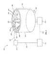
FIG. 1 is a perspective view of a cold spray nozzle positioned within a bearing according to an embodiment of the invention. -
FIG. 2 is a perspective view of a plurality of cold spray nozzles positioned within a bearing according to an embodiment of the invention. - Wherever possible, the same reference numbers will be used throughout the drawings to represent the same parts.
- Provided is a coating process. Embodiments of the present disclosure, in comparison to processes and articles not using one or more of the features disclosed herein, decrease post-coating machining, increase uniformity of coating, increase efficiency of coating, or a combination thereof.
- Referring to
FIG. 1 , in one embodiment, acold spray apparatus 100 includes acold spray nozzle 102 positioned relative to abearing assembly 101. Thebearing assembly 101 includes any type of bearing such as, but not limited to, a gas turbine bearing, a full bearing, a half bearing, a damaged bearing, or a combination thereof. A powderedbabbitt material 103 is directed through thecold spray nozzle 102 to asurface 104 of thebearing assembly 101. Thesurface 104 includes, but is not limited to, a coated surface, a damaged surface, an uncoated surface, a surface having an area with diminished coating, or a combination thereof. Thecold spray nozzle 102 propels the powderedbabbitt material 103 to thesurface 104 of thebearing assembly 101. The powderedbabbitt material 103 adheres to thesurface 104 of thebearing assembly 101, forming acoating 105 on thesurface 104. In one embodiment, thecoating 105 is a re-coating of thesurface 104 of thebearing assembly 101. In a further embodiment, thesurface 104 of thebearing assembly 101 is not stripped prior to the re-coating. - In one embodiment, properties of the
coating 105 are electronically monitored and controlled through adjustments to thecold spray nozzle 102. Properties of thecoating 105 include, but are not limited to, thickness, distribution, or a combination thereof. Adjustment of thecold spray nozzle 102 includes, but is not limited to, speed of rotation, distribution of powderedbabbitt material 103, amount of the powderedbabbitt material 103 propelled, spray pattern of the powderedbabbitt material 103, or a combination thereof. - In one embodiment, a
coating monitor 110 acquiresinformation 120 corresponding to at least one property of thecoating 105 in real time. Thecoating monitor 110 acquiresinformation 120 through any suitable method capable of measuring any suitable property of thecoating 105 in real time. Suitable methods of measuring at least one property of thecoating 105 include, but are not limited to, visual light measurements (such as white light/blue light), laser thickness measurements, temperature measurements, or a combination thereof. Suitable properties of thecoating 105 for measurement include, but are not limited to, thickness, temperature, density, or a combination thereof. - The
coating monitor 110 generates afirst signal 121 based upon the properties of thecoating 105 and sends thefirst signal 121 to acoating analyzer 112. Thecoating analyzer 112 receives thefirst signal 121, analyzes the properties of thecoating 105, and generates asecond signal 122. Thecoating analyzer 112 sends thesecond signal 122 to acoating control device 114. Thesecond signal 122 includes information for adjusting thecold spray nozzle 102, to form a desired final coating, based upon the properties of thecoating 105 acquired in real time by thecoating monitor 110. In response to thesecond signal 122, thecoating control device 114 configures thecold spray nozzle 102 by altering the coating parameters or settings of thecold spray nozzle 102 or maintaining the coating parameters or settings of thecold spray nozzle 102. Suitable coating parameters capable of being altered include, speed of thecold spray nozzle 102, gas flows, coating path, or a combination thereof. Thecoating monitor 110 continues acquiringinformation 120 on the properties of thecoating 105 after thecoating control device 114 adjusts thecold spray nozzle 102, forming a continuous loop. - In one embodiment, the
coating control device 114 adjusts thecold spray nozzle 102 to form an even distribution of thecoating 105. In one embodiment, thecoating control device 114 adjusts thecold spray nozzle 102 to maintain a desirable thickness of thecoating 105. The desirable thickness of thecoating 105 is decreased as compared to a coating formed from centrifugal coating. Decreasing the thickness of thecoating 105 eliminates over-coating and/or a need for machining to finalize thecoating 105. In one embodiment, thecoating control device 114 directs thecold spray nozzle 102 to a damaged area of thebearing assembly 101. - The
cold spray apparatus 100 forms thecoating 105 on thesurface 104 by impacting the powderedbabbitt material 103 in the absence of significant heat input to the powderedbabbitt material 103. Thecold spraying process 100 substantially retains the phases and microstructure of the powderedbabbitt material 103. In one embodiment, the cold spraying (step 304) includes accelerating the powderedbabbitt material 103 to at least a predetermined velocity or velocity range, for example, based upon the below equation for a converging-diverging nozzle:
- In Equation 1, "A" is the area of an exit of the
cold spray nozzle 102 and "A*" is the area of a throat of thecold spray nozzle 102. "γ" is the ratio Cp/Cv of a process gas being used (Cp being the specific heat capacity at constant pressure and Cv being the specific heat capacity at constant volume). The gas flow parameters depend upon the ratio of A/A*. When thecold spray nozzle 102 operates in a choked condition, the exit gas velocity Mach number (M) is identifiable by Equation 1. Gas having a higher value for "γ" results in a higher Mach number. The powderedbabbitt material 103 impacts thesurface 104 of thebearing assembly 101 at the predetermined velocity or velocity range and the powderedbabbitt material 103 bonds to thesurface 104 of thebearing assembly 101 to form thecoating 105. - The
cold spray nozzle 102 is positioned a predetermined distance from thesurface 104 of the bearingassembly 101, for example, between about 10 mm and about 150 mm, between about 10 mm and about 50 mm, between about 50 mm and about 100 mm, between about 10 mm and about 30 mm, between about 30 mm and about 70 mm, between about 70 mm and about 100 mm, or any suitable combination or sub-combination thereof. In one embodiment, thecold spray nozzle 102 is positioned in a center of the bearingassembly 101. Thecold spray nozzle 102 positioned in the center of the bearingassembly 101 is rotated in place, providing an equal distance between thecold spray nozzle 102 and thesurface 104 throughout a 360° rotation. In one embodiment, thecold spray nozzle 102 forms a concentric arrangement within the bearingassembly 101. Thecold spray nozzle 102 in the concentric arrangement is moved in a circle within the bearingassembly 101 such that a distance between thecold spray nozzle 102 and thesurface 104 is maintained throughout a 360° movement. - In one embodiment, a babbitt material is a metal matrix that forms a surface layer. The metal matrix is a composite having crystals dispersed in a metal. In one embodiment, the babbitt material is used as a protective coating and/or a lubricant for the
surface 104 of the bearingassembly 101. The crystals are relatively hard as compared to the metal, and form a non-lubricating portion of the surface layer. The babbitt material includes, but is not limited to, tin, copper, lead, or a combination thereof. Suitable compositions of babbitt material include, but are not limited to, 90% tin and 10% copper; 89% tin, 7% antimony and 4% copper; 80% lead, 15% antimony and 5% tin; 76% copper and 24% lead; 75% lead and 10% tin; 67% copper, 28% tin and 5% lead; or combinations thereof. For babbitt material compositions including tin, friction from using thebearing assembly 101 generates heat which melts the tin in the babbitt material. The melted tin forms a lubricant for protecting thesurface 104 of the bearingassembly 101. - In one embodiment, the bearing
assembly 101 is rotated 106 while thecold spray nozzle 102 is held stationary. Therotation 106 of the bearingassembly 101 while spraying powderedbabbitt material 103 forms a circular strip of thecoating 105 over thesurface 104. In one embodiment, thecold spray nozzle 102 is rotated 107 while the bearingassembly 101 is held stationary. The rotation 107 of thecold spray nozzle 102 while spraying powderedbabbitt material 103 forms the circular strip of thecoating 105 over thesurface 104. - In one embodiment, the
cold spray nozzle 102 propels the powderedbabbitt material 103 in a pattern that covers a portion of aheight 109 of the bearingassembly 101. A full rotation of thecold spray nozzle 102 or the bearingassembly 101 forms the circular strip of thecoating 105 on thesurface 104 of the bearingassembly 101. Thecold spray nozzle 102 is adjusted relative to theheight 109 of the bearingassembly 101 andpowdered babbitt material 103 is propelled to anuncoated portion 108 of the bearingassembly 101. Thecold spray nozzle 102 or the bearingassembly 101 is fully rotated forming another circular strip of thecoating 105. The adjusting of the cold spray nozzle and the forming of the circular strip of thecoating 105 is repeated until thesurface 104 is adequately covered in thecoating 105. - Referring to
FIG. 2 , in one embodiment, a plurality ofcold spray nozzles 102 are positioned relative to abearing assembly 101. Each of thecold spray nozzles 102 propels the powderedbabbitt material 103 in a pattern that covers a portion of theheight 109 of the bearingassembly 101. An increase in the number of thecold spray nozzles 102 increases the portion of theheight 109 covered in thecoating 105 during a single full rotation. - An alternate
cold spray apparatus 100 includes a firstcold spray nozzle 202 and a secondcold spray nozzle 204 positioned relative to the bearingassembly 101. The firstcold spray nozzle 202 and the secondcold spray nozzle 204 both propel the powderedbabbitt material 103 to thesurface 104 of the bearingassembly 101. The firstcold spray nozzle 202 forms a firstcircular strip 207 of thecoating 105 at a first position, and the secondcold spray nozzle 204 forms a secondcircular strip 209 of thecoating 105 at a second position. The first position and the second position are similar, substantially similar, or differ relative to theheight 109 of the bearingassembly 101. In one embodiment, the firstcold spray nozzle 202 and the secondcold spray nozzle 204 face 180° apart, such that rotating the nozzles 180° forms thecoating 105 over 360° of thesurface 104 of the bearingassembly 101. In another embodiment, a separate feeder is provided for the firstcold spray nozzle 202 and the secondcold spray nozzle 204. The separate feeders permit the propulsion of different material combinations at one time, forming a composite or gradient in thecoating 105. Additionally, the separate feeders permit changes to a chemistry of thecoating 105 as a function of a thickness of the Babbitt material. - In one embodiment, speeds of rotation include, but are not limited to, between about .5 rotations per minute (RPM) and about 5 RPMs, between about 1 RPM and about 3 RPMs, between about 2 RPMs and about 4 RPMs, or any combination, sub-combination, range, or sub-range thereof. Suitable thicknesses of the
coating 105 include, but are not limited to, between about 1 mil and about 2000 mils, between about 1 mil and about 500 mils, between about 10 mils and about 500 mils, between about 20 mils and about 400 mils, between about 30 mils and about 200 mils, between about 40 mils and about 100 mils, or any suitable combination or sub-combination thereof. - While the invention has been described with reference to a preferred embodiment, it will be understood by those skilled in the art that various changes may be made and equivalents may be substituted for elements thereof without departing from the scope of the invention. In addition, many modifications may be made to adapt a particular situation or material to the teachings of the invention without departing from the essential scope thereof. Therefore, it is intended that the invention not be limited to the particular embodiment disclosed as the preferred mode contemplated for carrying out this invention, but that the invention will include all embodiments falling within the scope of the appended claims.
- Various aspects and embodiments of the present invention are defined by the following numbered clauses:
- 1. A cold spray coating process for propelling a powdered babbitt material using a cold spray nozzle, the cold spray coating process comprising:
- positioning the cold spray nozzle relative to a bearing assembly;
- rotating the bearing assembly; and
- directing the powdered babbitt material through the cold spray nozzle, to a surface of the rotating bearing assembly;
- wherein the powdered babbitt material adheres to the surface of the rotating bearing assembly, forming a coating on the surface of the rotating bearing assembly.
- 2. The cold spray coating process of clause 1, wherein the bearing assembly is a half bearing.
- 3. The cold spray coating process of any preceding clause, wherein the bearing assembly is a full bearing.
- 4. The cold spray coating process of any preceding clause, further comprising repairing a damaged bearing assembly.
- 5. The cold spray coating process of any preceding clause, further comprising re-coating the surface of the bearing assembly.
- 6. The cold spray coating process of any preceding clause, wherein the surface of the bearing assembly is not stripped prior to re-coating.
- 7. The cold spray coating process of any preceding clause, wherein the surface of the bearing assembly comprises an area having diminished coating.
- 8. The cold spray coating process of any preceding clause, further comprising evenly distributing the coating on the surface of the rotating bearing assembly.
- 9. The cold spray coating process of any preceding clause, wherein the coating is not machined prior to installation.
- 10. The cold spray coating process of any preceding clause, further comprising electronic monitoring of one or more properties of the coating.
- 11. The cold spray coating process of any preceding clause, further comprising real time monitoring of a thickness of the coating.
- 12. The cold spray coating process of any preceding clause, further comprising electronic control of the cold spray nozzle.
- 13. The cold spray coating process of any preceding clause, further comprising a plurality of the cold spray nozzles positioned relative to the bearing assembly.
- 14. The cold spray coating process of any preceding clause, wherein the powdered babbitt material includes tin, copper, lead, or a combination thereof.
- 15. The cold spray coating process of any preceding clause, wherein tin application is not required prior to directing the powdered metal material through the cold spray nozzle.
- 16. The cold spray coating process of any preceding clause, wherein rotating the bearing assembly is provided at a speed of rotation between about 0.5 rotations per minute and 5 rotations per minute.
- 17. The cold spray coating process of any preceding clause, wherein the powdered babbitt material has a composition, by weight, selected from the group of compositions consisting of
about 90% tin and about 10% copper;
about 89% tin, about 7% antimony, and about 4% copper;
about 80% lead, about 15% antimony, and about 5% tin;
about 76% copper and about 24% lead;
about 75% lead and about 10% tin;
about 67% copper, about 28% tin, and about 5% lead; and
combinations thereof. - 18. A cold spray coating process for propelling a powdered babbitt material using a cold spray nozzle, the cold spray coating process comprising:
- positioning the cold spray nozzle relative to a bearing assembly;
- rotating the cold spray nozzle; and
- directing the powdered babbitt material through the cold spray nozzle, to a surface of the bearing assembly;
- wherein the powdered babbitt material adheres to the surface of the bearing assembly, the rotating of the cold spray nozzle forming a coating on the surface of the bearing assembly.
- 19. A cold spray coating process for propelling a powdered babbitt material using a cold spray nozzle, the cold spray coating process comprising:
- positioning the cold spray nozzle relative to a bearing assembly;
- rotating the cold spray nozzle and the bearing assembly relative to each other;
- directing the powdered babbitt material through the cold spray nozzle, to a surface of the bearing assembly;
- adhering the powdered babbitt material to the surface of the bearing assembly, the adhering of the babbitt material forming a coating on the surface of the bearing assembly;
- monitoring one or more properties of the coating on the surface of the bearing assembly with a coating monitor;
- transmitting a first signal from the coating monitor to a coating analyzer;
- analyzing the first signal from the coating monitor with the coating analyzer;
- sending a second signal from the coating analyzer to a coating control device; and
- configuring the cold spray nozzle with the coating control device in response to the second signal.
- 20. The cold spray coating process of any preceding clause, wherein manipulation of the cold spray nozzle comprises speed of rotation, distribution of powdered babbitt material, amount of the powdered babbitt material propelled, and spray pattern of the powdered babbitt material.
Claims (15)
- A cold spray coating process for propelling a powdered babbitt material (103) using a cold spray nozzle (102), the cold spray coating process comprising:positioning the cold spray nozzle (102) relative to a bearing assembly (101);rotating the bearing assembly (101); anddirecting the powdered babbitt material (103) through the cold spray nozzle (102), to a surface (104) of the rotating bearing assembly (101);wherein the powdered babbitt material (103) adheres to the surface (104) of the rotating bearing assembly (101), forming a coating (105) on the surface (104) of the rotating bearing assembly (101).
- The cold spray coating process of claim 1, further comprising repairing a damaged bearing assembly (101).
- The cold spray coating process of any preceding claim, further comprising re-coating the surface (104) of the bearing assembly (101).
- The cold spray coating process of claim 3, wherein the surface (104) of the bearing assembly (101) is not stripped prior to re-coating.
- The cold spray coating process of any preceding claim, wherein the surface (104) of the bearing assembly (101) comprises an area having diminished coating (105).
- The cold spray coating process of any preceding claim, further comprising evenly distributing the coating (105) on the surface (104) of the rotating bearing assembly (101).
- The cold spray coating process of any preceding claim, further comprising electronic monitoring of one or more properties of the coating (105).
- The cold spray coating process of any preceding claim, further comprising real time monitoring of a thickness of the coating (105).
- The cold spray coating process of any preceding claim, wherein the powdered babbitt material (103) includes tin, copper, lead, or a combination thereof.
- The cold spray coating process of any preceding claim, wherein tin application is not required prior to directing the powdered metal material through the cold spray nozzle (102).
- The cold spray coating process of any preceding claim, wherein rotating the bearing assembly (101) is provided at a speed of rotation between about 0.5 rotations per minute and 5 rotations per minute.
- The cold spray coating process of any preceding claim, wherein the powdered babbitt material (103) has a composition, by weight, selected from the group of compositions consisting of:about 90% tin and about 10% copper;about 89% tin, about 7% antimony, and about 4% copper;about 80% lead, about 15% antimony, and about 5% tin;about 76% copper and about 24% lead;about 75% lead and about 10% tin;about 67% copper, about 28% tin, and about 5% lead; andcombinations thereof.
- A cold spray coating process for propelling a powdered babbitt material (103) using a cold spray nozzle (102), the cold spray coating process comprising:positioning the cold spray nozzle (102) relative to a bearing assembly (101);rotating the cold spray nozzle (102); anddirecting the powdered babbitt material (103) through the cold spray nozzle (102), to a surface (104) of the bearing assembly (101);wherein the powdered babbitt material (103) adheres to the surface (104) of the bearing assembly (101), the rotating of the cold spray nozzle (102) forming a coating (105) on the surface of the bearing assembly (101).
- A cold spray coating process for propelling a powdered babbitt (103) material using a cold spray nozzle, the cold spray coating process comprising:positioning the cold spray nozzle relative to a bearing assembly;rotating the cold spray nozzle and the bearing assembly relative to each other;directing the powdered babbitt material through the cold spray nozzle, to a surface of the bearing assembly;adhering the powdered babbitt material to the surface of the bearing assembly, the adhering of the babbitt material forming a coating on the surface of the bearing assembly;monitoring one or more properties of the coating on the surface of the bearing assembly with a coating monitor;transmitting a first signal from the coating monitor to a coating analyzer;analyzing the first signal from the coating monitor with the coating analyzer;sending a second signal from the coating analyzer to a coating control device; andconfiguring the cold spray nozzle with the coating control device in response to the second signal.
- The cold spray coating process of claim 14, wherein manipulation of the cold spray nozzle (102) comprises speed of rotation, distribution of powdered babbitt material (103), amount of the powdered babbitt material (103) propelled, and spray pattern of the powdered babbitt material (103).
Applications Claiming Priority (1)
| Application Number | Priority Date | Filing Date | Title |
|---|---|---|---|
| US13/901,686 US9109291B2 (en) | 2013-05-24 | 2013-05-24 | Cold spray coating process |
Publications (2)
| Publication Number | Publication Date |
|---|---|
| EP2806049A1 true EP2806049A1 (en) | 2014-11-26 |
| EP2806049B1 EP2806049B1 (en) | 2018-08-22 |
Family
ID=50828697
Family Applications (1)
| Application Number | Title | Priority Date | Filing Date |
|---|---|---|---|
| EP14168673.3A Active EP2806049B1 (en) | 2013-05-24 | 2014-05-16 | Cold spray coating process |
Country Status (4)
| Country | Link |
|---|---|
| US (1) | US9109291B2 (en) |
| EP (1) | EP2806049B1 (en) |
| JP (1) | JP2015007282A (en) |
| CN (1) | CN104178760B (en) |
Cited By (3)
| Publication number | Priority date | Publication date | Assignee | Title |
|---|---|---|---|---|
| GB2545481A (en) * | 2015-12-18 | 2017-06-21 | Rolls Royce Plc | An assembly and a method of using the assembly |
| WO2017203190A1 (en) * | 2016-05-27 | 2017-11-30 | Saint Jean Industries | Method for manufacturing a part consisting at least partially of a metal alloy, and optimisation method |
| CN112962092A (en) * | 2021-02-05 | 2021-06-15 | 中国人民解放军第五七一九工厂 | Method for repairing abrasion of spline pipe sleeve teeth of aircraft engine |
Families Citing this family (13)
| Publication number | Priority date | Publication date | Assignee | Title |
|---|---|---|---|---|
| US9335296B2 (en) | 2012-10-10 | 2016-05-10 | Westinghouse Electric Company Llc | Systems and methods for steam generator tube analysis for detection of tube degradation |
| CN106435563B (en) * | 2016-10-27 | 2019-05-03 | 北京科技大学 | A kind of method for spraying babbitt coating on the steel back of bearing bush |
| US10226791B2 (en) | 2017-01-13 | 2019-03-12 | United Technologies Corporation | Cold spray system with variable tailored feedstock cartridges |
| US10315218B2 (en) | 2017-07-06 | 2019-06-11 | General Electric Company | Method for repairing turbine component by application of thick cold spray coating |
| US11273526B1 (en) | 2018-08-07 | 2022-03-15 | Kyle William Johnson | Systems and methods for application of stress corrosion cracking resistant cold spray coatings |
| CN109267064B (en) * | 2018-11-09 | 2020-04-28 | 成都青石激光科技有限公司 | Preparation method of iron-based alloy bearing bush wear-resistant layer |
| US11935662B2 (en) | 2019-07-02 | 2024-03-19 | Westinghouse Electric Company Llc | Elongate SiC fuel elements |
| KR102523509B1 (en) | 2019-09-19 | 2023-04-18 | 웨스팅하우스 일렉트릭 컴퍼니 엘엘씨 | Apparatus and Method of Use for Performing In Situ Adhesion Testing of Cold Spray Deposits |
| CN111560580B (en) * | 2020-06-22 | 2022-10-04 | 沈阳理工大学 | A kind of manufacturing method of tin-based babbitt coating containing carbon fiber C12 |
| CN111575628A (en) * | 2020-06-28 | 2020-08-25 | 沈阳理工大学 | A kind of preparation method of tin-based babbitt coating containing TiN and TiO2 |
| CN111519123B (en) * | 2020-06-29 | 2022-09-13 | 沈阳理工大学 | Preparation method of tin-based Babbitt alloy coating containing high carbon fibers |
| US20230338974A1 (en) * | 2022-04-22 | 2023-10-26 | Helmut P. Hoell | System and apparatus for applying babbitt materials and the like |
| NL2037798B1 (en) | 2024-01-16 | 2025-02-28 | Univ Taizhou | A tracking temperature and speed monitoring device and method for cold spray process |
Citations (4)
| Publication number | Priority date | Publication date | Assignee | Title |
|---|---|---|---|---|
| DE102004043914A1 (en) * | 2004-09-10 | 2006-03-16 | Linde Ag | Bronze slip bearing is fabricated by cold gas spray application of a suitable alloy |
| DE102006060021A1 (en) * | 2006-12-19 | 2008-06-26 | Ecka Granulate Gmbh & Co. Kg | Preparing heavy-duty coating composition containing e.g. tin, useful to coat on e.g. bearings, comprises introducing an input stock of the composition into a cold gas spraying system, cold gas spraying of metal layers on a base metal |
| US20100170937A1 (en) * | 2009-01-07 | 2010-07-08 | General Electric Company | System and Method of Joining Metallic Parts Using Cold Spray Technique |
| US20120128284A1 (en) * | 2009-06-17 | 2012-05-24 | Mahle Metal Leve S/A | Slide bearing, a manufacturing process and an internal combustion engine |
Family Cites Families (15)
| Publication number | Priority date | Publication date | Assignee | Title |
|---|---|---|---|---|
| US2381797A (en) | 1943-06-16 | 1945-08-07 | Aviat Corp | Method of babbitting |
| US4435448A (en) | 1983-04-21 | 1984-03-06 | Allis-Chalmers Corporation | Method for manufacturing babbitted bearings |
| JPS59219425A (en) * | 1983-05-25 | 1984-12-10 | N D C Kk | Production of bearing material |
| US6117565A (en) | 1996-05-24 | 2000-09-12 | Pioneer Motor Bearing Co. | Babbitted bearing having an improved bonding layer and a method of depositing same |
| JP3340335B2 (en) * | 1997-01-22 | 2002-11-05 | 日本パーカライジング株式会社 | Multi-layer plain bearing |
| ATE221929T1 (en) | 1998-03-14 | 2002-08-15 | Dana Corp | METHOD FOR PRODUCING A PLAIN BEARING COATING |
| JP2000345312A (en) * | 1999-06-08 | 2000-12-12 | Nippon Steel Hardfacing Co Ltd | Continuous thermal spraying method for outer peripheral faces of boiler tubes of panel-form and thermal spraying device therefor |
| JP4105516B2 (en) * | 2002-09-27 | 2008-06-25 | 大同メタル工業株式会社 | Film forming device for bearing inner surface |
| JP2004323875A (en) * | 2003-04-22 | 2004-11-18 | Fuji Technica Inc | Method and apparatus for depositing metallic film on free curved surface |
| DE102006023384A1 (en) * | 2006-05-17 | 2007-11-22 | Sms Demag Ag | Use of a sliding bearing |
| JP4943063B2 (en) * | 2006-06-09 | 2012-05-30 | 富士フイルム株式会社 | Film forming apparatus and film forming method |
| JP2008291285A (en) * | 2007-05-22 | 2008-12-04 | Ntn Corp | Coating film forming apparatus |
| JP2009275397A (en) * | 2008-05-14 | 2009-11-26 | West Nippon Expressway Engineering Chugoku Co Ltd | Guardrail remake system |
| JP2010111932A (en) * | 2008-11-07 | 2010-05-20 | Kanto Auto Works Ltd | Thermal spraying system |
| US20110193338A1 (en) * | 2010-02-09 | 2011-08-11 | General Electric Company | Threaded metal pipe |
-
2013
- 2013-05-24 US US13/901,686 patent/US9109291B2/en active Active
-
2014
- 2014-05-16 EP EP14168673.3A patent/EP2806049B1/en active Active
- 2014-05-19 JP JP2014102939A patent/JP2015007282A/en not_active Ceased
- 2014-05-23 CN CN201410220528.XA patent/CN104178760B/en not_active Expired - Fee Related
Patent Citations (4)
| Publication number | Priority date | Publication date | Assignee | Title |
|---|---|---|---|---|
| DE102004043914A1 (en) * | 2004-09-10 | 2006-03-16 | Linde Ag | Bronze slip bearing is fabricated by cold gas spray application of a suitable alloy |
| DE102006060021A1 (en) * | 2006-12-19 | 2008-06-26 | Ecka Granulate Gmbh & Co. Kg | Preparing heavy-duty coating composition containing e.g. tin, useful to coat on e.g. bearings, comprises introducing an input stock of the composition into a cold gas spraying system, cold gas spraying of metal layers on a base metal |
| US20100170937A1 (en) * | 2009-01-07 | 2010-07-08 | General Electric Company | System and Method of Joining Metallic Parts Using Cold Spray Technique |
| US20120128284A1 (en) * | 2009-06-17 | 2012-05-24 | Mahle Metal Leve S/A | Slide bearing, a manufacturing process and an internal combustion engine |
Cited By (5)
| Publication number | Priority date | Publication date | Assignee | Title |
|---|---|---|---|---|
| GB2545481A (en) * | 2015-12-18 | 2017-06-21 | Rolls Royce Plc | An assembly and a method of using the assembly |
| US10155236B2 (en) | 2015-12-18 | 2018-12-18 | Rolls-Royce Plc | Cold spray nozzle assembly and a method of depositing a powder material onto a surface of a component using the assembly |
| WO2017203190A1 (en) * | 2016-05-27 | 2017-11-30 | Saint Jean Industries | Method for manufacturing a part consisting at least partially of a metal alloy, and optimisation method |
| FR3051697A1 (en) * | 2016-05-27 | 2017-12-01 | Saint Jean Ind | PROCESS FOR MANUFACTURING A WORK PART AT LEAST PARTIALLY OF A METAL ALLOY, AND METHOD OF OPTIMIZATION |
| CN112962092A (en) * | 2021-02-05 | 2021-06-15 | 中国人民解放军第五七一九工厂 | Method for repairing abrasion of spline pipe sleeve teeth of aircraft engine |
Also Published As
| Publication number | Publication date |
|---|---|
| EP2806049B1 (en) | 2018-08-22 |
| CN104178760A (en) | 2014-12-03 |
| US20140349007A1 (en) | 2014-11-27 |
| JP2015007282A (en) | 2015-01-15 |
| US9109291B2 (en) | 2015-08-18 |
| CN104178760B (en) | 2018-02-02 |
Similar Documents
| Publication | Publication Date | Title |
|---|---|---|
| US9109291B2 (en) | Cold spray coating process | |
| Fukanuma et al. | In-flight particle velocity measurements with DPV-2000 in cold spray | |
| US6706319B2 (en) | Mixed powder deposition of components for wear, erosion and abrasion resistant applications | |
| JP4988824B2 (en) | Sliding bearing, method for producing such a sliding bearing and use thereof | |
| US6892954B2 (en) | Method for controlling a spray process | |
| WO2002034967A1 (en) | Abradable coating applied with cold spray technique | |
| EP3245007B1 (en) | Cold spray method to repair or in certain cases strengthen metals | |
| EP2902530B1 (en) | Method for applying a coating to a substrate | |
| EP0578219A1 (en) | Continuous melt-coating method and apparatus | |
| CA2802755C (en) | Method for repairing rotor blades | |
| JP2015007282A5 (en) | ||
| JP2016529391A (en) | Method for pretreating a substrate for thermal spraying of a metal coating | |
| Wei et al. | Splat formation during plasma spraying for 8 mol% yttria-stabilized zirconia droplets impacting on stainless steel substrate | |
| CN104507587A (en) | Movable mask for a thermal and/or kinetic coating system | |
| CA2951204A1 (en) | A method of coating a sheet of steel | |
| EP3093524A1 (en) | Shaft balancing system and method of balancing a shaft | |
| US7425115B2 (en) | Thermal turbomachine | |
| EP3463812B1 (en) | Apparatus for additive manufacturing of 3d objects using cold spraying | |
| Gedzevičius et al. | Influence of the particles velocity on the arc spraying coating adhesion | |
| JP4110436B2 (en) | Thermal spraying method and thermal spraying apparatus for inner surface of cylinder bore | |
| US20100260932A1 (en) | Cold spray method of applying aluminum seal strips | |
| EP1519791B1 (en) | High-temperature powder deposition apparatus and method utilizing feedback control | |
| US20150246371A1 (en) | Method of cold spraying components of a gas turbine engine mask therefor | |
| Mehdizadeh et al. | Adhesion of tin droplets impinging on a stainless steel plate: effect of substrate temperature and roughness | |
| US20130089726A1 (en) | Process of applying porous metallic structure and cold-sprayed article |
Legal Events
| Date | Code | Title | Description |
|---|---|---|---|
| PUAI | Public reference made under article 153(3) epc to a published international application that has entered the european phase |
Free format text: ORIGINAL CODE: 0009012 |
|
| 17P | Request for examination filed |
Effective date: 20140516 |
|
| AK | Designated contracting states |
Kind code of ref document: A1 Designated state(s): AL AT BE BG CH CY CZ DE DK EE ES FI FR GB GR HR HU IE IS IT LI LT LU LV MC MK MT NL NO PL PT RO RS SE SI SK SM TR |
|
| AX | Request for extension of the european patent |
Extension state: BA ME |
|
| R17P | Request for examination filed (corrected) |
Effective date: 20150526 |
|
| RBV | Designated contracting states (corrected) |
Designated state(s): AL AT BE BG CH CY CZ DE DK EE ES FI FR GB GR HR HU IE IS IT LI LT LU LV MC MK MT NL NO PL PT RO RS SE SI SK SM TR |
|
| 17Q | First examination report despatched |
Effective date: 20151112 |
|
| STAA | Information on the status of an ep patent application or granted ep patent |
Free format text: STATUS: EXAMINATION IS IN PROGRESS |
|
| GRAP | Despatch of communication of intention to grant a patent |
Free format text: ORIGINAL CODE: EPIDOSNIGR1 |
|
| STAA | Information on the status of an ep patent application or granted ep patent |
Free format text: STATUS: GRANT OF PATENT IS INTENDED |
|
| INTG | Intention to grant announced |
Effective date: 20180305 |
|
| GRAS | Grant fee paid |
Free format text: ORIGINAL CODE: EPIDOSNIGR3 |
|
| GRAA | (expected) grant |
Free format text: ORIGINAL CODE: 0009210 |
|
| STAA | Information on the status of an ep patent application or granted ep patent |
Free format text: STATUS: THE PATENT HAS BEEN GRANTED |
|
| AK | Designated contracting states |
Kind code of ref document: B1 Designated state(s): AL AT BE BG CH CY CZ DE DK EE ES FI FR GB GR HR HU IE IS IT LI LT LU LV MC MK MT NL NO PL PT RO RS SE SI SK SM TR |
|
| REG | Reference to a national code |
Ref country code: GB Ref legal event code: FG4D |
|
| REG | Reference to a national code |
Ref country code: CH Ref legal event code: EP |
|
| REG | Reference to a national code |
Ref country code: AT Ref legal event code: REF Ref document number: 1032611 Country of ref document: AT Kind code of ref document: T Effective date: 20180915 |
|
| REG | Reference to a national code |
Ref country code: IE Ref legal event code: FG4D |
|
| REG | Reference to a national code |
Ref country code: DE Ref legal event code: R096 Ref document number: 602014030735 Country of ref document: DE |
|
| REG | Reference to a national code |
Ref country code: NL Ref legal event code: MP Effective date: 20180822 |
|
| REG | Reference to a national code |
Ref country code: LT Ref legal event code: MG4D |
|
| PG25 | Lapsed in a contracting state [announced via postgrant information from national office to epo] |
Ref country code: FI Free format text: LAPSE BECAUSE OF FAILURE TO SUBMIT A TRANSLATION OF THE DESCRIPTION OR TO PAY THE FEE WITHIN THE PRESCRIBED TIME-LIMIT Effective date: 20180822 Ref country code: GR Free format text: LAPSE BECAUSE OF FAILURE TO SUBMIT A TRANSLATION OF THE DESCRIPTION OR TO PAY THE FEE WITHIN THE PRESCRIBED TIME-LIMIT Effective date: 20181123 Ref country code: NO Free format text: LAPSE BECAUSE OF FAILURE TO SUBMIT A TRANSLATION OF THE DESCRIPTION OR TO PAY THE FEE WITHIN THE PRESCRIBED TIME-LIMIT Effective date: 20181122 Ref country code: IS Free format text: LAPSE BECAUSE OF FAILURE TO SUBMIT A TRANSLATION OF THE DESCRIPTION OR TO PAY THE FEE WITHIN THE PRESCRIBED TIME-LIMIT Effective date: 20181222 Ref country code: RS Free format text: LAPSE BECAUSE OF FAILURE TO SUBMIT A TRANSLATION OF THE DESCRIPTION OR TO PAY THE FEE WITHIN THE PRESCRIBED TIME-LIMIT Effective date: 20180822 Ref country code: NL Free format text: LAPSE BECAUSE OF FAILURE TO SUBMIT A TRANSLATION OF THE DESCRIPTION OR TO PAY THE FEE WITHIN THE PRESCRIBED TIME-LIMIT Effective date: 20180822 Ref country code: BG Free format text: LAPSE BECAUSE OF FAILURE TO SUBMIT A TRANSLATION OF THE DESCRIPTION OR TO PAY THE FEE WITHIN THE PRESCRIBED TIME-LIMIT Effective date: 20181122 Ref country code: SE Free format text: LAPSE BECAUSE OF FAILURE TO SUBMIT A TRANSLATION OF THE DESCRIPTION OR TO PAY THE FEE WITHIN THE PRESCRIBED TIME-LIMIT Effective date: 20180822 Ref country code: LT Free format text: LAPSE BECAUSE OF FAILURE TO SUBMIT A TRANSLATION OF THE DESCRIPTION OR TO PAY THE FEE WITHIN THE PRESCRIBED TIME-LIMIT Effective date: 20180822 |
|
| REG | Reference to a national code |
Ref country code: AT Ref legal event code: MK05 Ref document number: 1032611 Country of ref document: AT Kind code of ref document: T Effective date: 20180822 |
|
| PG25 | Lapsed in a contracting state [announced via postgrant information from national office to epo] |
Ref country code: AL Free format text: LAPSE BECAUSE OF FAILURE TO SUBMIT A TRANSLATION OF THE DESCRIPTION OR TO PAY THE FEE WITHIN THE PRESCRIBED TIME-LIMIT Effective date: 20180822 Ref country code: LV Free format text: LAPSE BECAUSE OF FAILURE TO SUBMIT A TRANSLATION OF THE DESCRIPTION OR TO PAY THE FEE WITHIN THE PRESCRIBED TIME-LIMIT Effective date: 20180822 Ref country code: HR Free format text: LAPSE BECAUSE OF FAILURE TO SUBMIT A TRANSLATION OF THE DESCRIPTION OR TO PAY THE FEE WITHIN THE PRESCRIBED TIME-LIMIT Effective date: 20180822 |
|
| PG25 | Lapsed in a contracting state [announced via postgrant information from national office to epo] |
Ref country code: ES Free format text: LAPSE BECAUSE OF FAILURE TO SUBMIT A TRANSLATION OF THE DESCRIPTION OR TO PAY THE FEE WITHIN THE PRESCRIBED TIME-LIMIT Effective date: 20180822 Ref country code: PL Free format text: LAPSE BECAUSE OF FAILURE TO SUBMIT A TRANSLATION OF THE DESCRIPTION OR TO PAY THE FEE WITHIN THE PRESCRIBED TIME-LIMIT Effective date: 20180822 Ref country code: RO Free format text: LAPSE BECAUSE OF FAILURE TO SUBMIT A TRANSLATION OF THE DESCRIPTION OR TO PAY THE FEE WITHIN THE PRESCRIBED TIME-LIMIT Effective date: 20180822 Ref country code: CZ Free format text: LAPSE BECAUSE OF FAILURE TO SUBMIT A TRANSLATION OF THE DESCRIPTION OR TO PAY THE FEE WITHIN THE PRESCRIBED TIME-LIMIT Effective date: 20180822 Ref country code: EE Free format text: LAPSE BECAUSE OF FAILURE TO SUBMIT A TRANSLATION OF THE DESCRIPTION OR TO PAY THE FEE WITHIN THE PRESCRIBED TIME-LIMIT Effective date: 20180822 Ref country code: AT Free format text: LAPSE BECAUSE OF FAILURE TO SUBMIT A TRANSLATION OF THE DESCRIPTION OR TO PAY THE FEE WITHIN THE PRESCRIBED TIME-LIMIT Effective date: 20180822 |
|
| REG | Reference to a national code |
Ref country code: DE Ref legal event code: R097 Ref document number: 602014030735 Country of ref document: DE |
|
| PG25 | Lapsed in a contracting state [announced via postgrant information from national office to epo] |
Ref country code: DK Free format text: LAPSE BECAUSE OF FAILURE TO SUBMIT A TRANSLATION OF THE DESCRIPTION OR TO PAY THE FEE WITHIN THE PRESCRIBED TIME-LIMIT Effective date: 20180822 Ref country code: SM Free format text: LAPSE BECAUSE OF FAILURE TO SUBMIT A TRANSLATION OF THE DESCRIPTION OR TO PAY THE FEE WITHIN THE PRESCRIBED TIME-LIMIT Effective date: 20180822 Ref country code: SK Free format text: LAPSE BECAUSE OF FAILURE TO SUBMIT A TRANSLATION OF THE DESCRIPTION OR TO PAY THE FEE WITHIN THE PRESCRIBED TIME-LIMIT Effective date: 20180822 |
|
| PLBE | No opposition filed within time limit |
Free format text: ORIGINAL CODE: 0009261 |
|
| STAA | Information on the status of an ep patent application or granted ep patent |
Free format text: STATUS: NO OPPOSITION FILED WITHIN TIME LIMIT |
|
| 26N | No opposition filed |
Effective date: 20190523 |
|
| PG25 | Lapsed in a contracting state [announced via postgrant information from national office to epo] |
Ref country code: SI Free format text: LAPSE BECAUSE OF FAILURE TO SUBMIT A TRANSLATION OF THE DESCRIPTION OR TO PAY THE FEE WITHIN THE PRESCRIBED TIME-LIMIT Effective date: 20180822 |
|
| PG25 | Lapsed in a contracting state [announced via postgrant information from national office to epo] |
Ref country code: MC Free format text: LAPSE BECAUSE OF FAILURE TO SUBMIT A TRANSLATION OF THE DESCRIPTION OR TO PAY THE FEE WITHIN THE PRESCRIBED TIME-LIMIT Effective date: 20180822 |
|
| REG | Reference to a national code |
Ref country code: BE Ref legal event code: MM Effective date: 20190531 |
|
| PG25 | Lapsed in a contracting state [announced via postgrant information from national office to epo] |
Ref country code: LU Free format text: LAPSE BECAUSE OF NON-PAYMENT OF DUE FEES Effective date: 20190516 |
|
| PG25 | Lapsed in a contracting state [announced via postgrant information from national office to epo] |
Ref country code: TR Free format text: LAPSE BECAUSE OF FAILURE TO SUBMIT A TRANSLATION OF THE DESCRIPTION OR TO PAY THE FEE WITHIN THE PRESCRIBED TIME-LIMIT Effective date: 20180822 |
|
| PG25 | Lapsed in a contracting state [announced via postgrant information from national office to epo] |
Ref country code: IE Free format text: LAPSE BECAUSE OF NON-PAYMENT OF DUE FEES Effective date: 20190516 |
|
| PG25 | Lapsed in a contracting state [announced via postgrant information from national office to epo] |
Ref country code: BE Free format text: LAPSE BECAUSE OF NON-PAYMENT OF DUE FEES Effective date: 20190531 |
|
| PG25 | Lapsed in a contracting state [announced via postgrant information from national office to epo] |
Ref country code: PT Free format text: LAPSE BECAUSE OF FAILURE TO SUBMIT A TRANSLATION OF THE DESCRIPTION OR TO PAY THE FEE WITHIN THE PRESCRIBED TIME-LIMIT Effective date: 20181222 |
|
| PG25 | Lapsed in a contracting state [announced via postgrant information from national office to epo] |
Ref country code: CY Free format text: LAPSE BECAUSE OF FAILURE TO SUBMIT A TRANSLATION OF THE DESCRIPTION OR TO PAY THE FEE WITHIN THE PRESCRIBED TIME-LIMIT Effective date: 20180822 |
|
| PG25 | Lapsed in a contracting state [announced via postgrant information from national office to epo] |
Ref country code: HU Free format text: LAPSE BECAUSE OF FAILURE TO SUBMIT A TRANSLATION OF THE DESCRIPTION OR TO PAY THE FEE WITHIN THE PRESCRIBED TIME-LIMIT; INVALID AB INITIO Effective date: 20140516 Ref country code: MT Free format text: LAPSE BECAUSE OF FAILURE TO SUBMIT A TRANSLATION OF THE DESCRIPTION OR TO PAY THE FEE WITHIN THE PRESCRIBED TIME-LIMIT Effective date: 20180822 |
|
| PG25 | Lapsed in a contracting state [announced via postgrant information from national office to epo] |
Ref country code: MK Free format text: LAPSE BECAUSE OF FAILURE TO SUBMIT A TRANSLATION OF THE DESCRIPTION OR TO PAY THE FEE WITHIN THE PRESCRIBED TIME-LIMIT Effective date: 20180822 |
|
| PGFP | Annual fee paid to national office [announced via postgrant information from national office to epo] |
Ref country code: IT Payment date: 20230420 Year of fee payment: 10 Ref country code: FR Payment date: 20230420 Year of fee payment: 10 Ref country code: DE Payment date: 20230419 Year of fee payment: 10 Ref country code: CH Payment date: 20230602 Year of fee payment: 10 |
|
| PGFP | Annual fee paid to national office [announced via postgrant information from national office to epo] |
Ref country code: GB Payment date: 20230420 Year of fee payment: 10 |
|
| REG | Reference to a national code |
Ref country code: DE Ref legal event code: R081 Ref document number: 602014030735 Country of ref document: DE Owner name: GENERAL ELECTRIC TECHNOLOGY GMBH, CH Free format text: FORMER OWNER: GENERAL ELECTRIC COMPANY, SCHENECTADY, NY, US |
|
| REG | Reference to a national code |
Ref country code: GB Ref legal event code: 732E Free format text: REGISTERED BETWEEN 20240222 AND 20240228 |
|
| REG | Reference to a national code |
Ref country code: DE Ref legal event code: R119 Ref document number: 602014030735 Country of ref document: DE |
|
| REG | Reference to a national code |
Ref country code: CH Ref legal event code: PL |
|
| GBPC | Gb: european patent ceased through non-payment of renewal fee |
Effective date: 20240516 |
|
| PG25 | Lapsed in a contracting state [announced via postgrant information from national office to epo] |
Ref country code: CH Free format text: LAPSE BECAUSE OF NON-PAYMENT OF DUE FEES Effective date: 20240531 |
|
| PG25 | Lapsed in a contracting state [announced via postgrant information from national office to epo] |
Ref country code: DE Free format text: LAPSE BECAUSE OF NON-PAYMENT OF DUE FEES Effective date: 20241203 |
|
| PG25 | Lapsed in a contracting state [announced via postgrant information from national office to epo] |
Ref country code: FR Free format text: LAPSE BECAUSE OF NON-PAYMENT OF DUE FEES Effective date: 20240531 |
|
| PG25 | Lapsed in a contracting state [announced via postgrant information from national office to epo] |
Ref country code: GB Free format text: LAPSE BECAUSE OF NON-PAYMENT OF DUE FEES Effective date: 20240516 Ref country code: IT Free format text: LAPSE BECAUSE OF NON-PAYMENT OF DUE FEES Effective date: 20240516 |