EP2805901B1 - Scraper, holding device and scraper assembly - Google Patents
Scraper, holding device and scraper assembly Download PDFInfo
- Publication number
- EP2805901B1 EP2805901B1 EP14168578.4A EP14168578A EP2805901B1 EP 2805901 B1 EP2805901 B1 EP 2805901B1 EP 14168578 A EP14168578 A EP 14168578A EP 2805901 B1 EP2805901 B1 EP 2805901B1
- Authority
- EP
- European Patent Office
- Prior art keywords
- head
- scraper blade
- holding device
- scraper
- groove
- Prior art date
- Legal status (The legal status is an assumption and is not a legal conclusion. Google has not performed a legal analysis and makes no representation as to the accuracy of the status listed.)
- Active
Links
- 230000007704 transition Effects 0.000 claims description 37
- 238000004140 cleaning Methods 0.000 claims description 4
- 239000000463 material Substances 0.000 description 15
- 238000011161 development Methods 0.000 description 9
- 230000018109 developmental process Effects 0.000 description 9
- 230000033001 locomotion Effects 0.000 description 4
- 238000007790 scraping Methods 0.000 description 4
- 230000000712 assembly Effects 0.000 description 3
- 238000000429 assembly Methods 0.000 description 3
- 238000004519 manufacturing process Methods 0.000 description 3
- 238000005299 abrasion Methods 0.000 description 2
- 238000004132 cross linking Methods 0.000 description 2
- 229920002635 polyurethane Polymers 0.000 description 2
- 239000004814 polyurethane Substances 0.000 description 2
- 230000000284 resting effect Effects 0.000 description 2
- 230000009286 beneficial effect Effects 0.000 description 1
- 238000005266 casting Methods 0.000 description 1
- 239000011248 coating agent Substances 0.000 description 1
- 238000000576 coating method Methods 0.000 description 1
- 238000007373 indentation Methods 0.000 description 1
- 238000005192 partition Methods 0.000 description 1
Images


Classifications
-
- B—PERFORMING OPERATIONS; TRANSPORTING
- B65—CONVEYING; PACKING; STORING; HANDLING THIN OR FILAMENTARY MATERIAL
- B65G—TRANSPORT OR STORAGE DEVICES, e.g. CONVEYORS FOR LOADING OR TIPPING, SHOP CONVEYOR SYSTEMS OR PNEUMATIC TUBE CONVEYORS
- B65G45/00—Lubricating, cleaning, or clearing devices
- B65G45/10—Cleaning devices
- B65G45/12—Cleaning devices comprising scrapers
- B65G45/16—Cleaning devices comprising scrapers with scraper biasing means
Definitions
- the present invention relates to the field of scraper assemblies, comprising at least one scraper blade and a holding device, for cleaning of conveyor belts and, more particularly, to scraper assemblies where the at least one scraper blade easily can be replaced.
- Scraper assemblies used to keep conveyor belts clean and free of undesirable deposits generally comprises at least one scraper blade arranged to abut a conveyor belt for mechanical scraping of the belt.
- the scraper blade is generally arranged in the proximity of the conveyor wheel at the turn around point of the conveyor belt, just after the conveyor belt has discharged its load.
- the scraper blade may be arranged in contact with the conveyor belt or just over the surface of the conveyor belt.
- the scraper blade will be exposed to extensive, continuous abrasion from the conveyor belt. Consequently, it is desirable that the scraper blade is arranged at a distance from the conveyor belt, but at the same time the closer the scraping blade is arranged to the conveyor belt, the better will the scraping characteristics of the scraper assembly be.
- the object of the present invention is to provide an inventive product for improved mounting and dismounting of replaceable scraper blades of a scraper assembly where the previously mentioned problems are partly avoided.
- the invention comprises a scraper assembly as stated in claim 11, a scraper blade as stated in claim 1 and a holding device as stated in claim 6.
- the inventive scraper assembly will obtain beneficial properties overcoming some of the previous problems within the technical field.
- the inventive scarper assembly provides a robust and simple scraper assembly arrangement, where the scraper blades may be replaced one by one independently.
- the inventive scraper blade is provided with a front and a back side.
- the front side is adapted to be directed towards said conveyor belt and said back side is arranged opposite said front side.
- the scraper blade is provided with a top portion adapted to abut against the conveyor belt.
- the scraper blade is also provided with a base portion adapted to be mounted on a holding device and an intermediate portion connecting the top portion with the base portion.
- the base portion of the inventive scraper blade is formed as a tongue, which tongue extends from the intermediate portion, such that a groove is formed, which groove extends along the front side of the base portion and adjacent to the intermediate portion, i.e. in the transition between the intermediate portion and the base portion.
- the groove is provided with an inner part, which is provided with a semi circular cross section.
- the base portion and especially the groove are adapted to interact with the holding device of the scraper assembly in order to achieve a quick exchange of scraper blades.
- the inventive holding device is provided with an elongated shape and a U-shaped cross section, created by a first and a second wall part and a bottom extending there between.
- the holding device can be provided to hold one or several scraper blades, wherein in most common applications a plurality of scraper blades is preferred.
- the first wall part of said inventive holding device is provided with a first head, which first head is provided with a cross section with an essentially circularly shaped outer circumference, such as a three quarter circular cross section.
- the first head is adapted to be fitted in the groove of the scraper blade.
- the first head is arranged at the top of the first wall part, wherein the top of said first wall is opposite to an end of the first wall part connecting to the bottom.
- the first head is adapted to be fitted into said groove of said inventive scraper blade such that said first head forms a pivot shoulder for said scraper blade, whereby said scraper blade can be pivoted about said first head between at least a first and a second position.
- the circularity of the first head of the holding device and the circularity of the groove of the scraper blade are adapted such that they can form a pivot joint when the first head is fitted into the groove.
- the scraper blade In the first position the scraper blade can be fitted onto or removed from the holding device in that the groove is fitted about or removed from the first head. In the first position a scraper blade arranged in the holding device can easily be removed from the holding device, and thereby be replaced by a new scraper blade. After mounting of a scraper blade on the holding device, the scraper blade is in the first position, whereby by pivot the scraper blade into the second position the scraper blade is fixed to the holding device and in its working position. In the second position the scraper blade is adapted to be arranged such that it abuts the conveyor belt for cleaning or like of the conveyor belt. In the second position the scraper blade is arranged in its working position, i.e. is fixed in the holding device and the only movement it can perform is the pivot motion in direction towards the first position. In the second the tongue protrudes under the first head and the second wall limits the space on the backside of the tongue such that the second head cannot be removed from the groove.
- the inventive scraper assembly enables an exchange of scraper blades in a quick manner, because one scraper blade can be removed from a scraper assembly without removing other adjacent scraper blades. This is enabled because the scraper blade is able to pivot about the first head of the holding device.
- said first head is arranged such relative said first wall, that said first head is directed into said U-shaped section and thereby extends into said U-shaped cross section. It is however preferred that an outer surface of said first wall has a smooth transition into said first head. A large portion of the tongue can thereby protrude in under the first head of the holding device and thereby fix the scraper blade to the holding device.
- the backside of the tongue is provided with a transition surface, wherein the transition surface is connecting to the front side.
- the transition surface reaches from the transition of the intermediate portion to the front side of the tongue.
- the transition surface is rounded.
- the transition surface can be rounded such that it is one continuous surface or be divided into a plurality of surfaces.
- the shape of the transition surface must be such that the scraper blade can pivot freely between its first and second position without any interference with neither of the second wall and/or the bottom of the holding device.
- the scraper blade must be pivoted approximately 90° when being pivoted from the first position to the second position.
- the first head is adapted to receive protrusions of fixing means.
- the first head is provided with circularly shaped recesses on each short side of the elongated holding device, wherein the recesses are adapted to receive the protrusions of fixing means.
- the circularly shaped recesses are preferably provided in the middle of the first head.
- the recesses may be formed either by the first head being provided with a circular hole through the whole head or by a circular indentations in the short ends of the first head.
- Developments of the holding device with a circular, all trough passing hole has the advantage that they will be lighter and that less material is needed for manufacturing.
- the tongue is narrower than the intermediate portion, such that a first and a second support surface is created in the transition of the intermediate portion and the tongue at the front and the back side respectively.
- the second wall part of the inventive holding device is provided with the previously mentioned second head.
- the second head is provided by a flange extending from the second wall part.
- the flange is directed into the U-shaped cross section and thereby extending into the U-shaped cross section.
- Arranging the second head as according to the invention has the advantage that it can be abutted by the second support surface of the scraper blade, which contributes to improved stability when the scraper blade is positioned in the second position, and that the flange forms a protruding lip which may be used for locking purposes.
- the scraper blade will abut the conveyor with its top portion such, that a reaction force upon the scraper blade acts to pivot the scraper blade towards its second position. A further rotation of the scraper blade, beyond the second position is prevented in that the scraper blade is supported by the second head upon its second support surface.
- the first head is provided at a distance from the bottom of the U-shaped cross section such that a stop surface is provided between the first head and the bottom.
- the stop surface is constituted by the first wall part.
- the scraper blade is provided with a corresponding third support surface provided at the end of the tongue, between the groove and the connection of the transition surface to the front side.
- the third support surface is thereby provided at the front side below the groove.
- the third support surface is adapted to abut against the stop surface of the holding device when the scraper blade is positioned in its second position, whereby the stop surface is adapted to take up the reaction force upon the scraper blade together with the flange upon the second wall part.
- the second and the third support surface are adapted to make contact with their respective stop surface essentially simultaneously.
- the width of an opening of the groove at least corresponding to a diameter of the semi circular cross section of the inner part of the groove. This has the advantage of that the opening of the groove is not hindering for the first head to fit the dimensions of the inner part of the groove, wherein the scraper blade can be made in a stiffer material.
- the transition surface of the scraper blade is provided with at least one locking protrusion, wherein the locking protrusion is provided at the back side of the transition surface. Further, the locking protrusion is provided such upon the transition surface that in the second position it is positioned between the second head and the bottom of the holding device. Further, the transition surface is thereby provided such, that when the locking protrusion passes the second head when the scraper blade pivots between its first and second position the locking protrusion must be pressed past the second head. The locking protrusion interacts with the second head and thereby provides a snap fit of the scraper blade, preventing the scraper blade to freely move between its first and second position.
- the locking protrusion can be provided as a continuous elongated shoulder extending essentially parallel with the extension of the scraper blade or as a plurality of protrusion arranged parallel with the extension of the scraper blade.
- the scraper blade is made out of one piece of material.
- Using scraper blades made out of one piece of material has the advantage of that easy, fast end cost efficient manufacturing methods may be used.
- the scraper blade can be made out of different materials offering different material properties in regards of e.g. hardness, abrasion resistance, durability etc., depending on what properties that is desired for the scraper blade. It is also possible to coat the exposed surface area of the scraper blade abutting the conveyor belt with a coating or to enhance the exposed surface area in another way, e.g. by arranging a wear resistant material on the abutting surface.
- the scraper blade made out of one piece of a polyurethane material.
- Polyurethane materials have the advantage of being hard, tough and rigid, if high amounts of cross linking are present. Also other polymeric materials, preferably with high amount of cross linking or other structural properties providing desired material properties, are however possible.
- the at least one scraper blade is generally arranged in the holding device to clean the conveyor belt, wherein this at least one scraper blade needs to cover the complete width of the conveyor belt. Either may one scraper blade with substantially the same width as the conveyor belt be arranged in the holding device, or may a plurality of scraper blades, together having substantially the same width as the conveyor belt, be arranged in the holding device.
- the holding device is adapted to receive a plurality of scraper blades.
- a plurality of scraper blades has the advantage of that just the most worn scraper blades may be replaced, which will lower the cost for replaced scraper blades.
- a middle scraper blade can be exchanged without removing the adjacent scraper blades. This is due to the inventive pivot arrangement of the scraper blades upon the holding device.
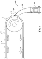
- Figure 1 shows a schematic view of an example of an inventive scraper assembly 100 arranged at a conveyor belt 10, wherein the inventive scraper assembly 100 comprises a scraper blade 200 and a holding device 300 according to the invention.
- the scraper blade 200 is accordingly arranged in the holding device 300. Further, as is schematically shown in Fig. 1 , the scraper blade is arranged to abut the conveyor belt 10 such that material 11 transported by the conveyor belt 10, is scraped off the conveyor belt 10.
- FIG 2a shows a schematic side view of an example of the inventive scraper blade 200.
- the scraper blade has a front side 203 and a back side 204.
- the scraper blade 200 comprises a top portion 201, a base portion 210 and an intermediate portion 202, wherein the intermediate portion 202 is connecting the top portion 201 with the base portion 210.
- the top portion 201 is configured to abut a conveyor belt for scraping of the conveyor belt.
- the base portion 210 of the scraper blade 200 is provided as a tongue 211 extending from the intermediate portion 202.
- the tongue 211 is narrower than the intermediate portion 202 and is arranged substantially in the middle in between the front and the back side 203, 204 relative the intermediate portion 202.
- the tongue 211 is additionally bent in approximately 90° towards the front side 203, such that a groove 212 is provided at the front side 203 of the scraper blade 200.
- the inner part 213 of the groove 212 is provided with a semi circular cross section.
- the back side 204 of the base portion 210 is a transition surface 220 extending from the intermediate portion 202 to the front side 203 of the base portion 210. At the transition surface 220 a locking protrusion 215 is provided as an elongated shoulder 215.
- the scraper blade 200 is provided with a first, a second and a third support surface 205; 206; 214.
- the first support surface 205 is provided at the front side 203, and is formed in the transition of the intermediate portion 202 to the tongue 211, due to that the tongue 211 is narrower than the intermediate portion 202.
- the second support surface is provided at the back side 204, and is formed in the transition of the intermediate portion 202 to the tongue 211, due to that the tongue 211 is narrower than the intermediate portion 202 and located centered relative the intermediate portion 202.
- the third support surface 214 is provided at the end of the tongue 211 in between the groove 212 and where the transition surface 220 connects to the front side 203.
- Figure 2b shows a schematic perspective view of the embodiment of the inventive scraper blade 200, showing that the scraper blade 200 has an elongated shape with a width w1.
- Fig. 2b additionally shows how the groove 212, formed between the tongue 211 and the intermediate portion 202, extends along the front side 203 of the scraper blade 200, wherein the groove 212 has the same width w1 as the scraper blade 200 and extends adjacent to the intermediate portion 202.
- the short sides of the scraper blade 200 are substantially flat, enabling that a plurality of scraper blades may be arranged side by side.
- the scraper blade 200 is also provided with the locking protrusion 215.
- Figure 3a shows a schematic side view of an embodiment of the inventive holding device 300 with an H-shaped cross section.
- the upper part of the holding device 300 consequently has a U-shaped cross section.
- the U-shaped portion of the holding device 300 is formed by a first wall part, a second wall part and a bottom 310; 320; 307, wherein the first wall part 310 and the second wall part 320 are substantially parallel.
- the bottom 307 extending between the first wall part 310 and the second wall part 320 and is substantially perpendicular to the first and second wall part 310; 320.
- the first wall part 310 is provided with a first head 311, which is arranged at the top of the U-shape.
- the first head 311 is provided with a cross section with an essentially circularly shaped outer circumference. Further, the first head 311 is provided at the top of the first wall part 310 such that the first head 311 protrudes into the U-shaped cross section of the holding device 300. The distance the first head 311 protrude inside the U-shaped cross section is about equal with the diameter of the circular cross section of the first head 311.
- the second wall part 320 is provided with a second head 321, which is arranged at the top of the U-shape.
- the second head 321 is formed as a flange extending into the U-shape.
- An upper surface of the first head 311 is substantially on the same level as an upper surface of the second head 321.
- a stop surface 312 is provided at the first wall part 310 below the first head 311 and the bottom 307. The stop surface is formed by partition of the first wall part 310 extending between the bottom 307 and the first head 311.
- the first head 311 is provided with a circularly shaped recess 313, which preferably extends along the whole length of the first head 311.
- Figure 3b shows a schematic perspective view of the holding device 300.
- Fig. 3b has the holding device 300 an elongated shape with a length w2.
- the first wall part, the second wall part, the bottom, the first head and the second head 310; 320; 307; 311; 321 extends along the whole holding device 300 and thereby have the same length w2 as the holding device 300.
- said first head 310 of said holding device 300 may be provided as a ring with a minor ring segment missing such that an open ring is formed. This may be an advantageous design when manufacturing said elongated holding device 300, especially during a casting process.
- Figure 4a and b shows a schematic view of an embodiment of an inventive scraper assembly 100 comprising the scraper blade 200 and the holding device 300.
- the scraper blade 200 is adapted to be fitted onto the holding device 300 in that the groove 212 of the scraper blade 200 receives the first head 213 of the holding device 300.
- the scraper blade 200 can thereby pivot about the first head 213 between a first and a second position, wherein the scraper blade 200 is shown in its first position in figure 4a and in its second position in figure 4b .
- the scraper blade 200 can easily be mounted and dismounted from the holding device 300, in order to exchange a worn out scraper blade 200.
- the scraper blade In the second position the scraper blade is pivoted approximately 90° from its first position. In the second position the first support surface 205 abutting and resting on the top surface of the first head 311 and the second support surface 206 abutting and resting on the top surface of the second head 321 and the third support surface 214 is abutting the stop surface 312.
- the scraper assembly 100 is mounted at a conveyor belt (as shown in figure 1 ) such that the top portion 201 of the scraper blade 200 is pressed against the conveyor belt, whereby the second and third support surfaces 206; 214 is pressed against the top surface of the flange 321 and the stop surface 312.
- transition surface 220 is configured such that the pivot motion of the scraper blade 200 can be performed without the transition surface 220 interfere with either of the second wall 320 nor the bottom 307 of the holding device 300.
- the locking protrusion 215 is provided such upon the transition surface 220, that it is located below the second head 321 when the scraper blade 200 is positioned in its second position. Further, the transition surface 220 with the locking protrusion 214 and the second head 206 is provided such relative each other that the locking protrusion 215 provides a snap lock for the scraper blade 200 when the scraper blade is pivoted such that the locking protrusion passes the second head 206 in a pivot motion from the first to the second position.
- Figure 5 shows a schematic perspective view of an inventive scraper assembly 100 provided with four scraper blades 200a, 200b, 200c, 200d arranged side by side in an elongated holding device 300.
- One of the middle scraper blades 200b is arranged in its first position.
- the scraper blade 200b can be removed from the inventive scraper assembly 100, whereby the other scraper blades 200a, 200c, 200d not have to be moved or tampered with in order to exchange of the scraper blade 200b.
- Figure 6a and b discloses a short end of the inventive scraper assembly 100.
- the holding device 300 By providing the holding device 300 with an H-shaped cross section, it can be fitted on to a beam 400 in a convenient manner.
- a locking device 500 is provided in order to lock the scraper assembly 100 to the beam 400.
- the locking device 500 has a lower U-shaped cross section, such that it is adapted to be fitted upon a beam 400 and is provided with a first and a second attachment pin 501, 502 upon a flange 503.
- the first attachment pin 501 is adapted to fit into the circular shaped recesses 313 in the first head of the holding device 300.
- the second attachment pin 502 is adapted to be fitted in between the transition surface 220 of the scraper blade 200 and the second wall part 320 of the holding device 300.
- the first and the second attachment pin 501, 502 is positioned into the holding device 300 by sliding the locking device 500 into its locking position ( figure 6b ).
- the locking device 500 is fixed to the beam with a bolt 504 and a nut 505, wherein the bolt can be arranged through the beam 400 or below the beam 400.
Landscapes
- Engineering & Computer Science (AREA)
- Mechanical Engineering (AREA)
- Cleaning In General (AREA)
- Cleaning In Electrography (AREA)
Description
- The present invention relates to the field of scraper assemblies, comprising at least one scraper blade and a holding device, for cleaning of conveyor belts and, more particularly, to scraper assemblies where the at least one scraper blade easily can be replaced.
- Scraper assemblies used to keep conveyor belts clean and free of undesirable deposits, generally comprises at least one scraper blade arranged to abut a conveyor belt for mechanical scraping of the belt. In order to be as effective as possible, the scraper blade is generally arranged in the proximity of the conveyor wheel at the turn around point of the conveyor belt, just after the conveyor belt has discharged its load. The scraper blade may be arranged in contact with the conveyor belt or just over the surface of the conveyor belt.
- If the scraper is arranged in contact with the conveyor belt the scraper blade will be exposed to extensive, continuous abrasion from the conveyor belt. Consequently, it is desirable that the scraper blade is arranged at a distance from the conveyor belt, but at the same time the closer the scraping blade is arranged to the conveyor belt, the better will the scraping characteristics of the scraper assembly be.
- Further, in order to overcome this problem different materials or different configurations of the surface area of the scraper blade that abuts the conveyor belt may be used. However, this approach will not prevent wear of the scraper blades.
- Generally the wear caused by the conveyor belt and the material transported thereon, on said a scraper is most significant at a central portions of the scraper abutting the middle of the conveyor belt. Consequently, if more than one scraper blade is used the wear of the centrally arranged scraper blades will be more significant than the wear of the outer arranged scraper blades.
- Consequently, the scraper blades will be exposed to extensive wear resulting in that the scraper blades have limited lifetime. Replacing worn out scraper blades may be costly both due to the material cost and due to that the transport line, including the conveyor belt, needs to be stopped during the replacement of the scraper blades. It is desired that a scraper blade can be replaced in a quick and efficient manner. Document
US 2013/026008 A1 discloses a scraper blade, a holding device and a scraper assembly according to the preamble ofclaims 1, 6 and 11 respectively. DocumentUS 4 349 934 A discloses a knife block for drum dryers and flakers, the knife block is provided with a slot for attachments purposes. - The object of the present invention is to provide an inventive product for improved mounting and dismounting of replaceable scraper blades of a scraper assembly where the previously mentioned problems are partly avoided. The invention comprises a scraper assembly as stated in
claim 11, a scraper blade as stated in claim 1 and a holding device as stated in claim 6. By combining the inventive scraper blade with the inventive holding device the inventive scraper assembly will obtain beneficial properties overcoming some of the previous problems within the technical field. The inventive scarper assembly provides a robust and simple scraper assembly arrangement, where the scraper blades may be replaced one by one independently. - The inventive scraper blade is provided with a front and a back side. The front side is adapted to be directed towards said conveyor belt and said back side is arranged opposite said front side. Further, the scraper blade is provided with a top portion adapted to abut against the conveyor belt. The scraper blade is also provided with a base portion adapted to be mounted on a holding device and an intermediate portion connecting the top portion with the base portion.
- The base portion of the inventive scraper blade is formed as a tongue, which tongue extends from the intermediate portion, such that a groove is formed, which groove extends along the front side of the base portion and adjacent to the intermediate portion, i.e. in the transition between the intermediate portion and the base portion. The groove is provided with an inner part, which is provided with a semi circular cross section. The base portion and especially the groove are adapted to interact with the holding device of the scraper assembly in order to achieve a quick exchange of scraper blades.
- The inventive holding device is provided with an elongated shape and a U-shaped cross section, created by a first and a second wall part and a bottom extending there between. The holding device can be provided to hold one or several scraper blades, wherein in most common applications a plurality of scraper blades is preferred.
- The first wall part of said inventive holding device is provided with a first head, which first head is provided with a cross section with an essentially circularly shaped outer circumference, such as a three quarter circular cross section. The first head is adapted to be fitted in the groove of the scraper blade. The first head is arranged at the top of the first wall part, wherein the top of said first wall is opposite to an end of the first wall part connecting to the bottom.
- The first head is adapted to be fitted into said groove of said inventive scraper blade such that said first head forms a pivot shoulder for said scraper blade, whereby said scraper blade can be pivoted about said first head between at least a first and a second position. The circularity of the first head of the holding device and the circularity of the groove of the scraper blade are adapted such that they can form a pivot joint when the first head is fitted into the groove.
- In the first position the scraper blade can be fitted onto or removed from the holding device in that the groove is fitted about or removed from the first head. In the first position a scraper blade arranged in the holding device can easily be removed from the holding device, and thereby be replaced by a new scraper blade. After mounting of a scraper blade on the holding device, the scraper blade is in the first position, whereby by pivot the scraper blade into the second position the scraper blade is fixed to the holding device and in its working position. In the second position the scraper blade is adapted to be arranged such that it abuts the conveyor belt for cleaning or like of the conveyor belt. In the second position the scraper blade is arranged in its working position, i.e. is fixed in the holding device and the only movement it can perform is the pivot motion in direction towards the first position. In the second the tongue protrudes under the first head and the second wall limits the space on the backside of the tongue such that the second head cannot be removed from the groove.
- The inventive scraper assembly enables an exchange of scraper blades in a quick manner, because one scraper blade can be removed from a scraper assembly without removing other adjacent scraper blades. This is enabled because the scraper blade is able to pivot about the first head of the holding device.
- It can be foreseen that said first head is arranged such relative said first wall, that said first head is directed into said U-shaped section and thereby extends into said U-shaped cross section. It is however preferred that an outer surface of said first wall has a smooth transition into said first head. A large portion of the tongue can thereby protrude in under the first head of the holding device and thereby fix the scraper blade to the holding device.
- The backside of the tongue is provided with a transition surface, wherein the transition surface is connecting to the front side. The transition surface reaches from the transition of the intermediate portion to the front side of the tongue. Especially, the transition surface is rounded. The transition surface can be rounded such that it is one continuous surface or be divided into a plurality of surfaces. However, the shape of the transition surface must be such that the scraper blade can pivot freely between its first and second position without any interference with neither of the second wall and/or the bottom of the holding device.
- It is preferred that the scraper blade must be pivoted approximately 90° when being pivoted from the first position to the second position.
- According to another development of the holding device the first head is adapted to receive protrusions of fixing means. This is enabled by that the first head is provided with circularly shaped recesses on each short side of the elongated holding device, wherein the recesses are adapted to receive the protrusions of fixing means. The circularly shaped recesses are preferably provided in the middle of the first head. Using recesses provided at the first head of the holding device has the advantage that the scraper assembly can easily and simply be arranged at desired location, if desired location is provided with the fixing means, without any need of additional fastening means.
- The recesses may be formed either by the first head being provided with a circular hole through the whole head or by a circular indentations in the short ends of the first head. Developments of the holding device with a circular, all trough passing hole has the advantage that they will be lighter and that less material is needed for manufacturing.
- According to yet a development of the inventive scraper blade, the tongue is narrower than the intermediate portion, such that a first and a second support surface is created in the transition of the intermediate portion and the tongue at the front and the back side respectively. When the scraper blade is positioned in the second position the first support surface of the scraper blade will abut the first head of the holding device and the second support surface of the scraper blade will abut a second head of the holding device, giving the advantage of that the scraper blade will be steadily arranged in the holding device.
- Further, the second wall part of the inventive holding device is provided with the previously mentioned second head. The second head is provided by a flange extending from the second wall part. According to a preferred development the flange is directed into the U-shaped cross section and thereby extending into the U-shaped cross section. Arranging the second head as according to the invention has the advantage that it can be abutted by the second support surface of the scraper blade, which contributes to improved stability when the scraper blade is positioned in the second position, and that the flange forms a protruding lip which may be used for locking purposes.
- Normally, when the inventive scraper assembly is in use, the scraper blade will abut the conveyor with its top portion such, that a reaction force upon the scraper blade acts to pivot the scraper blade towards its second position. A further rotation of the scraper blade, beyond the second position is prevented in that the scraper blade is supported by the second head upon its second support surface.
- According to yet another development of the inventive holding device the first head is provided at a distance from the bottom of the U-shaped cross section such that a stop surface is provided between the first head and the bottom. The stop surface is constituted by the first wall part. The scraper blade is provided with a corresponding third support surface provided at the end of the tongue, between the groove and the connection of the transition surface to the front side. The third support surface is thereby provided at the front side below the groove. The third support surface is adapted to abut against the stop surface of the holding device when the scraper blade is positioned in its second position, whereby the stop surface is adapted to take up the reaction force upon the scraper blade together with the flange upon the second wall part. Hence, the second and the third support surface are adapted to make contact with their respective stop surface essentially simultaneously.
- It is preferred that the width of an opening of the groove at least corresponding to a diameter of the semi circular cross section of the inner part of the groove. This has the advantage of that the opening of the groove is not hindering for the first head to fit the dimensions of the inner part of the groove, wherein the scraper blade can be made in a stiffer material.
- According to a development of the scraper blade and the scraper assembly the transition surface of the scraper blade is provided with at least one locking protrusion, wherein the locking protrusion is provided at the back side of the transition surface. Further, the locking protrusion is provided such upon the transition surface that in the second position it is positioned between the second head and the bottom of the holding device. Further, the transition surface is thereby provided such, that when the locking protrusion passes the second head when the scraper blade pivots between its first and second position the locking protrusion must be pressed past the second head. The locking protrusion interacts with the second head and thereby provides a snap fit of the scraper blade, preventing the scraper blade to freely move between its first and second position.
- The locking protrusion can be provided as a continuous elongated shoulder extending essentially parallel with the extension of the scraper blade or as a plurality of protrusion arranged parallel with the extension of the scraper blade.
- According to a preferred development of the inventive scraper assembly, and especially of the inventive scraper blade, the scraper blade is made out of one piece of material. Using scraper blades made out of one piece of material has the advantage of that easy, fast end cost efficient manufacturing methods may be used. However, the scraper blade can be made out of different materials offering different material properties in regards of e.g. hardness, abrasion resistance, durability etc., depending on what properties that is desired for the scraper blade. It is also possible to coat the exposed surface area of the scraper blade abutting the conveyor belt with a coating or to enhance the exposed surface area in another way, e.g. by arranging a wear resistant material on the abutting surface.
- In a preferred development of the inventive scraper blade is the scraper blade made out of one piece of a polyurethane material. Polyurethane materials have the advantage of being hard, tough and rigid, if high amounts of cross linking are present. Also other polymeric materials, preferably with high amount of cross linking or other structural properties providing desired material properties, are however possible.
- The at least one scraper blade is generally arranged in the holding device to clean the conveyor belt, wherein this at least one scraper blade needs to cover the complete width of the conveyor belt. Either may one scraper blade with substantially the same width as the conveyor belt be arranged in the holding device, or may a plurality of scraper blades, together having substantially the same width as the conveyor belt, be arranged in the holding device.
- According to an advantageous development of the inventive scraper assembly, the holding device is adapted to receive a plurality of scraper blades. Using a plurality of scraper blades has the advantage of that just the most worn scraper blades may be replaced, which will lower the cost for replaced scraper blades. In the inventive scraper assembly a middle scraper blade can be exchanged without removing the adjacent scraper blades. This is due to the inventive pivot arrangement of the scraper blades upon the holding device.
- The present invention will now be described in detail with reference to the figures, wherein:
-
Fig. 1 shows a schematic view of an example of an inventive scraper assembly arranged at a conveyor belt, -
Fig. 2a shows a schematic side view of an example of an inventive scraper blade, -
Fig. 2b shows a schematic perspective view of an example of an inventive scraper blade, -
Fig. 3a shows a schematic side view of an example of an inventive, H-shaped holding device, -
Fig. 3b shows a schematic perspective view of an example of an inventive holding device, -
Fig. 4a shows a schematic view of an example of an inventive scraper blade arranged in an inventive holding device, wherein said scraper blade is positioned in a first position, -
Fig. 4b shows a schematic view of an example of an inventive scraper blade arranged in an inventive holding device, wherein said scraper blade is positioned in a second position, and -
Fig. 5 shows a schematic perspective view of an example of four inventive scraper blades arranged in an inventive holding device. - In the following only one embodiment of the invention is shown and described, simply by way of illustration of one mode of carrying out the invention.
-
Figure 1 shows a schematic view of an example of aninventive scraper assembly 100 arranged at aconveyor belt 10, wherein theinventive scraper assembly 100 comprises ascraper blade 200 and aholding device 300 according to the invention. Thescraper blade 200 is accordingly arranged in theholding device 300. Further, as is schematically shown inFig. 1 , the scraper blade is arranged to abut theconveyor belt 10 such thatmaterial 11 transported by theconveyor belt 10, is scraped off theconveyor belt 10. -
Figure 2a shows a schematic side view of an example of theinventive scraper blade 200. The scraper blade has afront side 203 and aback side 204. Thescraper blade 200 comprises atop portion 201, a base portion 210 and anintermediate portion 202, wherein theintermediate portion 202 is connecting thetop portion 201 with the base portion 210. Thetop portion 201 is configured to abut a conveyor belt for scraping of the conveyor belt. The base portion 210 of thescraper blade 200 is provided as atongue 211 extending from theintermediate portion 202. - The
tongue 211 is narrower than theintermediate portion 202 and is arranged substantially in the middle in between the front and theback side intermediate portion 202. Thetongue 211 is additionally bent in approximately 90° towards thefront side 203, such that agroove 212 is provided at thefront side 203 of thescraper blade 200. Theinner part 213 of thegroove 212 is provided with a semi circular cross section. Theback side 204 of the base portion 210 is atransition surface 220 extending from theintermediate portion 202 to thefront side 203 of the base portion 210. At the transition surface 220 a lockingprotrusion 215 is provided as anelongated shoulder 215. - Further, the
scraper blade 200 is provided with a first, a second and athird support surface 205; 206; 214. Thefirst support surface 205 is provided at thefront side 203, and is formed in the transition of theintermediate portion 202 to thetongue 211, due to that thetongue 211 is narrower than theintermediate portion 202. The second support surface is provided at theback side 204, and is formed in the transition of theintermediate portion 202 to thetongue 211, due to that thetongue 211 is narrower than theintermediate portion 202 and located centered relative theintermediate portion 202. Thethird support surface 214 is provided at the end of thetongue 211 in between thegroove 212 and where thetransition surface 220 connects to thefront side 203. -
Figure 2b shows a schematic perspective view of the embodiment of theinventive scraper blade 200, showing that thescraper blade 200 has an elongated shape with a width w1.Fig. 2b additionally shows how thegroove 212, formed between thetongue 211 and theintermediate portion 202, extends along thefront side 203 of thescraper blade 200, wherein thegroove 212 has the same width w1 as thescraper blade 200 and extends adjacent to theintermediate portion 202. According to the embodiment of theinventive scraper blade 200 shown inFig. 2b the short sides of thescraper blade 200 are substantially flat, enabling that a plurality of scraper blades may be arranged side by side. Thescraper blade 200 is also provided with the lockingprotrusion 215. -
Figure 3a shows a schematic side view of an embodiment of theinventive holding device 300 with an H-shaped cross section. The upper part of the holdingdevice 300 consequently has a U-shaped cross section. The U-shaped portion of the holdingdevice 300 is formed by a first wall part, a second wall part and a bottom 310; 320; 307, wherein thefirst wall part 310 and thesecond wall part 320 are substantially parallel. The bottom 307 extending between thefirst wall part 310 and thesecond wall part 320 and is substantially perpendicular to the first andsecond wall part 310; 320. Thefirst wall part 310 is provided with afirst head 311, which is arranged at the top of the U-shape. Thefirst head 311 is provided with a cross section with an essentially circularly shaped outer circumference. Further, thefirst head 311 is provided at the top of thefirst wall part 310 such that thefirst head 311 protrudes into the U-shaped cross section of the holdingdevice 300. The distance thefirst head 311 protrude inside the U-shaped cross section is about equal with the diameter of the circular cross section of thefirst head 311. - The
second wall part 320 is provided with asecond head 321, which is arranged at the top of the U-shape. Thesecond head 321 is formed as a flange extending into the U-shape. An upper surface of thefirst head 311 is substantially on the same level as an upper surface of thesecond head 321. Further astop surface 312 is provided at thefirst wall part 310 below thefirst head 311 and the bottom 307. The stop surface is formed by partition of thefirst wall part 310 extending between the bottom 307 and thefirst head 311. Thefirst head 311 is provided with a circularly shapedrecess 313, which preferably extends along the whole length of thefirst head 311. -
Figure 3b shows a schematic perspective view of the holdingdevice 300. As can be seen inFig. 3b has the holdingdevice 300 an elongated shape with a length w2. It can further be seen that the first wall part, the second wall part, the bottom, the first head and thesecond head 310; 320; 307; 311; 321 extends along thewhole holding device 300 and thereby have the same length w2 as the holdingdevice 300. - It should also be pointed out that said
first head 310 of saidholding device 300, provided with a cross section with an essentially circularly shaped outer circumference, may be provided as a ring with a minor ring segment missing such that an open ring is formed. This may be an advantageous design when manufacturing saidelongated holding device 300, especially during a casting process.Figure 4a and b shows a schematic view of an embodiment of aninventive scraper assembly 100 comprising thescraper blade 200 and the holdingdevice 300. Thescraper blade 200 is adapted to be fitted onto the holdingdevice 300 in that thegroove 212 of thescraper blade 200 receives thefirst head 213 of the holdingdevice 300. - The
scraper blade 200 can thereby pivot about thefirst head 213 between a first and a second position, wherein thescraper blade 200 is shown in its first position infigure 4a and in its second position infigure 4b . - In the first position the
scraper blade 200 can easily be mounted and dismounted from the holdingdevice 300, in order to exchange a worn outscraper blade 200. - In the second position the scraper blade is pivoted approximately 90° from its first position. In the second position the
first support surface 205 abutting and resting on the top surface of thefirst head 311 and thesecond support surface 206 abutting and resting on the top surface of thesecond head 321 and thethird support surface 214 is abutting thestop surface 312. Thescraper assembly 100 is mounted at a conveyor belt (as shown infigure 1 ) such that thetop portion 201 of thescraper blade 200 is pressed against the conveyor belt, whereby the second and third support surfaces 206; 214 is pressed against the top surface of theflange 321 and thestop surface 312. - Additionally, the
transition surface 220 is configured such that the pivot motion of thescraper blade 200 can be performed without thetransition surface 220 interfere with either of thesecond wall 320 nor the bottom 307 of the holdingdevice 300. - Additionally, the locking
protrusion 215 is provided such upon thetransition surface 220, that it is located below thesecond head 321 when thescraper blade 200 is positioned in its second position. Further, thetransition surface 220 with the lockingprotrusion 214 and thesecond head 206 is provided such relative each other that the lockingprotrusion 215 provides a snap lock for thescraper blade 200 when the scraper blade is pivoted such that the locking protrusion passes thesecond head 206 in a pivot motion from the first to the second position. -
Figure 5 shows a schematic perspective view of aninventive scraper assembly 100 provided with fourscraper blades elongated holding device 300. One of themiddle scraper blades 200b is arranged in its first position. As can be seen from its first position thescraper blade 200b can be removed from theinventive scraper assembly 100, whereby theother scraper blades scraper blade 200b. -
Figure 6a and b discloses a short end of theinventive scraper assembly 100. By providing theholding device 300 with an H-shaped cross section, it can be fitted on to abeam 400 in a convenient manner. Further, alocking device 500 is provided in order to lock thescraper assembly 100 to thebeam 400. Thelocking device 500 has a lower U-shaped cross section, such that it is adapted to be fitted upon abeam 400 and is provided with a first and asecond attachment pin flange 503. Thefirst attachment pin 501 is adapted to fit into the circular shapedrecesses 313 in the first head of the holdingdevice 300. Thesecond attachment pin 502 is adapted to be fitted in between thetransition surface 220 of thescraper blade 200 and thesecond wall part 320 of the holdingdevice 300. The first and thesecond attachment pin device 300 by sliding thelocking device 500 into its locking position (figure 6b ). Thelocking device 500 is fixed to the beam with abolt 504 and anut 505, wherein the bolt can be arranged through thebeam 400 or below thebeam 400.
Claims (14)
- A scraper blade (200) for cleaning of a conveyor belt (10), said scraper blade (200) is provided with• a front and a back side (203, 204), whereby said front side (203) is adapted to be directed towards said conveyor belt (10) and said back side (204) is arranged opposite said front side (203),• a top portion (201) adapted to abut against said conveyor belt (10),• a base portion (210) adapted to be mounted on a holding device (300), and• an intermediate portion (202) connecting said top portion (201) with said base portion (210),said base portion (210) is formed as a tongue (211), which tongue (211) extends from said intermediate portion (202), such that a groove (212) is formed,
the groove (212) extends along said front side (203) of said base portion (210) and adjacent said intermediate portion (202), wherein said groove (212) is provided with an inner part (213) with a semi-circular cross section, characterised in, that the backside (204) of said tongue (211) is provided with a transition surface (220), and said transition surface (220) is rounded, and in that the transition surface (220) is connecting to the front side (203). - A scraper blade (200) according to claim 1, wherein said tongue (211) is narrower than said intermediate portion (202) such that a first and a second support surface (205, 206) is created in the transition of said intermediate portion (202) and said tongue (211) at the front and the back side (203, 204) respectively.
- A scraper blade (200) according to claim 1 or 2, wherein a third support surface (214) is provided at the end of said tongue (211) at said front side (203) below said groove (212).
- A scraper blade (200) according to any of the preceding claim, wherein a width of an opening of said groove (212) at least corresponds to a diameter (d) of said semi-circular cross section.
- A scraper blade (200) according to any of the preceding claims, wherein said transition surface (220) is provided with a locking protrusion (215) provided at said back side (204).
- A holding device (300) for receiving a base portion (210) of a scraper blade (200), wherein said holding device (300) is provided with an elongate shape and an U-shaped cross section created by a first and a second wall part (310, 320) and a bottom (307) whereby said first wall part (310) is provided with a first head (311), characterised in that first head (311) is provided with a cross section with a circularly shaped outer circumference.
- A holding device (300) according to claim 6, wherein said second wall part (320) is provided with a second head (321), which second head (321) is provided by a flange extending from said second wall part (320).
- A holding device (300) according to claim 7, wherein said flange is directed into said U-shaped cross section.
- A holding device (300) according to any of the preceding claims 6-8, wherein said first head (311) is provided such that it extends into said U-shaped cross section.
- A holding device (300) according to any of the preceding claims 6-9, wherein said first head (311) is provided at a distance from said bottom (307) of said U-shaped cross section such, that a stop surface (312) is provided between said first head (311) and said bottom (301).
- A scraper assembly (100) for cleaning of a conveyor belt (10), wherein said scraper assembly (100) comprising a scraper blade (200) and a holding device (300), wherein said scraper assembly (100) is provided with;• a front and a back side (203, 204), whereby said front side (203) is adapted to be directed towards said conveyor belt (10) and said back side (204) is arranged opposite said front side (203), andsaid scraper blade (200) is provided with;• a top portion (201) adapted to be mounted against said conveyor belt (10),• a base portion (210) adapted to be mounted on a holding device (300),• an intermediate portion (202) connecting said top portion (201) with said base portion (210), andsaid holding device (300) is provided with;• an elongated shape and an U-shaped cross section, created by a first and a second wall part (310, 320) and a bottom (307),whereby
said base portion (210) is formed as a tongue (211), which extends from said intermediate portion (202), such that a groove (212) is formed, which groove extends along said front side (203) of said base portion (210) and adjacent said intermediate portion (202),
, and a transition surface (220) is provided at said tongue (211) back side (204), wherein said groove (212) is provided with an inner part (213), which is provided with a semi circular cross section, and said transition surface (220) is connecting to said front side (203), characterised in, that said first wall part (310) is provided with a first head (311), which first head (311) is provided with a cross section with a circularly shaped outer circumference, wherein
said first head (311) can be fitted into said groove (212) such that said first head (311) forms a pivot shoulder for said scraper blade (200), whereby said scraper blade (200) can be pivoted about said first head (311) between at least a first and a second position, wherein in said first position said first head (311) can be fitted into said groove (212), and in said second position transition surface (220) connects to said front side (203) in between said first head (311) and said bottom (307). - A scraper assembly (100) according to claim 11, wherein said tongue (211) is narrower than said intermediate portion (202) such that a first and a second support surface (205, 206) is created in the transition of said intermediate portion (202) and said tongue (211) at the front and the back side (203, 204) respectively, and said second wall part (320) is provided with a second head (321), which second head (321) is provided by a flange extending from said second wall part (320), whereby in said first position;• said first support surface (205) is adapted to rest upon said first head (311), and• said second support surface (206) is adapted to rest upon said second head (321).
- A scraper assembly (100) according to claim 11 or 12, wherein a third support surface (214) is provided between said groove (212) and said connection to said front side (203) of said transition surface (220), and said third support surface (214) is adapted to rest upon a stop surface (312) provided by the first wall (310) in between said bottom (301) and said first head (311).
- A scraper assembly (100) according to any of the claims 11 to 13, wherein said transition surface (220) is provided with a locking protrusion (215) provided along said back side (204) and said locking protrusion (215) is provided such upon said transition surface (220) that in said second position it is positioned between said second head (321) and said bottom (301) of said holding device (300).
Applications Claiming Priority (1)
| Application Number | Priority Date | Filing Date | Title |
|---|---|---|---|
| SE1350625 | 2013-05-22 |
Publications (2)
| Publication Number | Publication Date |
|---|---|
| EP2805901A1 EP2805901A1 (en) | 2014-11-26 |
| EP2805901B1 true EP2805901B1 (en) | 2016-07-27 |
Family
ID=50732823
Family Applications (1)
| Application Number | Title | Priority Date | Filing Date |
|---|---|---|---|
| EP14168578.4A Active EP2805901B1 (en) | 2013-05-22 | 2014-05-16 | Scraper, holding device and scraper assembly |
Country Status (3)
| Country | Link |
|---|---|
| EP (1) | EP2805901B1 (en) |
| ES (1) | ES2595081T3 (en) |
| PL (1) | PL2805901T3 (en) |
Families Citing this family (2)
| Publication number | Priority date | Publication date | Assignee | Title |
|---|---|---|---|---|
| CN106198151B (en) * | 2016-08-31 | 2022-12-23 | 湖南三德科技股份有限公司 | Scraping and sweeping type divider for material conveying equipment |
| CN115045477B (en) * | 2021-03-08 | 2023-06-30 | 广东博智林机器人有限公司 | Scraper device |
Citations (1)
| Publication number | Priority date | Publication date | Assignee | Title |
|---|---|---|---|---|
| US4349934A (en) * | 1981-02-17 | 1982-09-21 | Thomas Margittai | Doctoring knife for drum dryers and flakers |
Family Cites Families (2)
| Publication number | Priority date | Publication date | Assignee | Title |
|---|---|---|---|---|
| US6401911B1 (en) * | 1999-01-15 | 2002-06-11 | Martin Engineering Company | Differential wear conveyor belt scraper blade |
| US8393459B2 (en) * | 2011-07-28 | 2013-03-12 | Martin Engineering Company | Conveyor belt scraper assembly comprising scraper members that are clamped together and method pertaining to the same |
-
2014
- 2014-05-16 EP EP14168578.4A patent/EP2805901B1/en active Active
- 2014-05-16 ES ES14168578.4T patent/ES2595081T3/en active Active
- 2014-05-16 PL PL14168578T patent/PL2805901T3/en unknown
Patent Citations (1)
| Publication number | Priority date | Publication date | Assignee | Title |
|---|---|---|---|---|
| US4349934A (en) * | 1981-02-17 | 1982-09-21 | Thomas Margittai | Doctoring knife for drum dryers and flakers |
Also Published As
| Publication number | Publication date |
|---|---|
| EP2805901A1 (en) | 2014-11-26 |
| ES2595081T3 (en) | 2016-12-27 |
| PL2805901T3 (en) | 2017-01-31 |
Similar Documents
| Publication | Publication Date | Title |
|---|---|---|
| EP2551220B1 (en) | Conveyer belt scraper assembly and related assembling method | |
| AU2009101050A4 (en) | A conveyor belt cleaner blade | |
| US6581754B2 (en) | Conveyor belt cleaner | |
| EP2805901B1 (en) | Scraper, holding device and scraper assembly | |
| US20040188224A1 (en) | Scraper blade for conveyor belts | |
| US9751694B2 (en) | Side-flexing conveyors | |
| US6315105B1 (en) | Conveyor belt scraping apparatus | |
| EP1568559B1 (en) | A windscreen wiper device | |
| FI76043B (en) | RENGOERINGSARRANGEMANG FOER TRANSPORTBAND. | |
| EP1167249A1 (en) | Self-locking pin mounting arrangement for conveyor belt cleaner scraper blades | |
| US4779716A (en) | Conveyor belt cleaner | |
| US6354428B1 (en) | Conveyor belt scraping apparatus | |
| CN103764525A (en) | Chain link comprising an articulation section and a fork section separated by a slide section | |
| US2756868A (en) | Replaceable flight conveyor chain | |
| CN103930358B (en) | There is scraper and the using method thereof of the loose material travelling belt of dust baffle plate | |
| US9327688B2 (en) | Windscreen wiper device | |
| JP5115484B2 (en) | Wiper blade | |
| WO2010135722A1 (en) | Double edged belt scraper blade | |
| CN112469553B (en) | Circular knife, cutting assembly and method for cutting tire components | |
| JP2012000551A (en) | Screw conveyor | |
| WO2003074393A1 (en) | Conveyor belt scraper blade assembly | |
| US20130298372A1 (en) | Removable profile assembly and method of use | |
| GB2364985A (en) | Conveyor belt scraper | |
| CN117441073A (en) | Energy guiding chain with a skid plate and attachable skid plate therefor | |
| CN1451517A (en) | Runner |
Legal Events
| Date | Code | Title | Description |
|---|---|---|---|
| PUAI | Public reference made under article 153(3) epc to a published international application that has entered the european phase |
Free format text: ORIGINAL CODE: 0009012 |
|
| 17P | Request for examination filed |
Effective date: 20140516 |
|
| AK | Designated contracting states |
Kind code of ref document: A1 Designated state(s): AL AT BE BG CH CY CZ DE DK EE ES FI FR GB GR HR HU IE IS IT LI LT LU LV MC MK MT NL NO PL PT RO RS SE SI SK SM TR |
|
| AX | Request for extension of the european patent |
Extension state: BA ME |
|
| R17P | Request for examination filed (corrected) |
Effective date: 20150526 |
|
| RBV | Designated contracting states (corrected) |
Designated state(s): AL AT BE BG CH CY CZ DE DK EE ES FI FR GB GR HR HU IE IS IT LI LT LU LV MC MK MT NL NO PL PT RO RS SE SI SK SM TR |
|
| GRAP | Despatch of communication of intention to grant a patent |
Free format text: ORIGINAL CODE: EPIDOSNIGR1 |
|
| INTG | Intention to grant announced |
Effective date: 20150921 |
|
| INTG | Intention to grant announced |
Effective date: 20160216 |
|
| GRAS | Grant fee paid |
Free format text: ORIGINAL CODE: EPIDOSNIGR3 |
|
| GRAA | (expected) grant |
Free format text: ORIGINAL CODE: 0009210 |
|
| AK | Designated contracting states |
Kind code of ref document: B1 Designated state(s): AL AT BE BG CH CY CZ DE DK EE ES FI FR GB GR HR HU IE IS IT LI LT LU LV MC MK MT NL NO PL PT RO RS SE SI SK SM TR |
|
| REG | Reference to a national code |
Ref country code: GB Ref legal event code: FG4D |
|
| REG | Reference to a national code |
Ref country code: CH Ref legal event code: EP |
|
| REG | Reference to a national code |
Ref country code: AT Ref legal event code: REF Ref document number: 815618 Country of ref document: AT Kind code of ref document: T Effective date: 20160815 |
|
| REG | Reference to a national code |
Ref country code: IE Ref legal event code: FG4D |
|
| REG | Reference to a national code |
Ref country code: DE Ref legal event code: R096 Ref document number: 602014002837 Country of ref document: DE |
|
| REG | Reference to a national code |
Ref country code: NL Ref legal event code: FP |
|
| REG | Reference to a national code |
Ref country code: SE Ref legal event code: TRGR |
|
| REG | Reference to a national code |
Ref country code: LT Ref legal event code: MG4D |
|
| REG | Reference to a national code |
Ref country code: NO Ref legal event code: T2 Effective date: 20160727 |
|
| REG | Reference to a national code |
Ref country code: ES Ref legal event code: FG2A Ref document number: 2595081 Country of ref document: ES Kind code of ref document: T3 Effective date: 20161227 |
|
| PG25 | Lapsed in a contracting state [announced via postgrant information from national office to epo] |
Ref country code: HR Free format text: LAPSE BECAUSE OF FAILURE TO SUBMIT A TRANSLATION OF THE DESCRIPTION OR TO PAY THE FEE WITHIN THE PRESCRIBED TIME-LIMIT Effective date: 20160727 Ref country code: RS Free format text: LAPSE BECAUSE OF FAILURE TO SUBMIT A TRANSLATION OF THE DESCRIPTION OR TO PAY THE FEE WITHIN THE PRESCRIBED TIME-LIMIT Effective date: 20160727 Ref country code: LT Free format text: LAPSE BECAUSE OF FAILURE TO SUBMIT A TRANSLATION OF THE DESCRIPTION OR TO PAY THE FEE WITHIN THE PRESCRIBED TIME-LIMIT Effective date: 20160727 Ref country code: IS Free format text: LAPSE BECAUSE OF FAILURE TO SUBMIT A TRANSLATION OF THE DESCRIPTION OR TO PAY THE FEE WITHIN THE PRESCRIBED TIME-LIMIT Effective date: 20161127 |
|
| PG25 | Lapsed in a contracting state [announced via postgrant information from national office to epo] |
Ref country code: GR Free format text: LAPSE BECAUSE OF FAILURE TO SUBMIT A TRANSLATION OF THE DESCRIPTION OR TO PAY THE FEE WITHIN THE PRESCRIBED TIME-LIMIT Effective date: 20161028 Ref country code: PT Free format text: LAPSE BECAUSE OF FAILURE TO SUBMIT A TRANSLATION OF THE DESCRIPTION OR TO PAY THE FEE WITHIN THE PRESCRIBED TIME-LIMIT Effective date: 20161128 Ref country code: BE Free format text: LAPSE BECAUSE OF FAILURE TO SUBMIT A TRANSLATION OF THE DESCRIPTION OR TO PAY THE FEE WITHIN THE PRESCRIBED TIME-LIMIT Effective date: 20160727 Ref country code: LV Free format text: LAPSE BECAUSE OF FAILURE TO SUBMIT A TRANSLATION OF THE DESCRIPTION OR TO PAY THE FEE WITHIN THE PRESCRIBED TIME-LIMIT Effective date: 20160727 |
|
| PG25 | Lapsed in a contracting state [announced via postgrant information from national office to epo] |
Ref country code: RO Free format text: LAPSE BECAUSE OF FAILURE TO SUBMIT A TRANSLATION OF THE DESCRIPTION OR TO PAY THE FEE WITHIN THE PRESCRIBED TIME-LIMIT Effective date: 20160727 Ref country code: EE Free format text: LAPSE BECAUSE OF FAILURE TO SUBMIT A TRANSLATION OF THE DESCRIPTION OR TO PAY THE FEE WITHIN THE PRESCRIBED TIME-LIMIT Effective date: 20160727 |
|
| REG | Reference to a national code |
Ref country code: DE Ref legal event code: R097 Ref document number: 602014002837 Country of ref document: DE |
|
| REG | Reference to a national code |
Ref country code: FR Ref legal event code: PLFP Year of fee payment: 4 |
|
| PG25 | Lapsed in a contracting state [announced via postgrant information from national office to epo] |
Ref country code: SM Free format text: LAPSE BECAUSE OF FAILURE TO SUBMIT A TRANSLATION OF THE DESCRIPTION OR TO PAY THE FEE WITHIN THE PRESCRIBED TIME-LIMIT Effective date: 20160727 Ref country code: DK Free format text: LAPSE BECAUSE OF FAILURE TO SUBMIT A TRANSLATION OF THE DESCRIPTION OR TO PAY THE FEE WITHIN THE PRESCRIBED TIME-LIMIT Effective date: 20160727 Ref country code: SK Free format text: LAPSE BECAUSE OF FAILURE TO SUBMIT A TRANSLATION OF THE DESCRIPTION OR TO PAY THE FEE WITHIN THE PRESCRIBED TIME-LIMIT Effective date: 20160727 Ref country code: BG Free format text: LAPSE BECAUSE OF FAILURE TO SUBMIT A TRANSLATION OF THE DESCRIPTION OR TO PAY THE FEE WITHIN THE PRESCRIBED TIME-LIMIT Effective date: 20161027 |
|
| PLBE | No opposition filed within time limit |
Free format text: ORIGINAL CODE: 0009261 |
|
| STAA | Information on the status of an ep patent application or granted ep patent |
Free format text: STATUS: NO OPPOSITION FILED WITHIN TIME LIMIT |
|
| 26N | No opposition filed |
Effective date: 20170502 |
|
| PG25 | Lapsed in a contracting state [announced via postgrant information from national office to epo] |
Ref country code: LU Free format text: LAPSE BECAUSE OF NON-PAYMENT OF DUE FEES Effective date: 20170531 Ref country code: SI Free format text: LAPSE BECAUSE OF FAILURE TO SUBMIT A TRANSLATION OF THE DESCRIPTION OR TO PAY THE FEE WITHIN THE PRESCRIBED TIME-LIMIT Effective date: 20160727 |
|
| REG | Reference to a national code |
Ref country code: CH Ref legal event code: PL |
|
| PG25 | Lapsed in a contracting state [announced via postgrant information from national office to epo] |
Ref country code: MC Free format text: LAPSE BECAUSE OF FAILURE TO SUBMIT A TRANSLATION OF THE DESCRIPTION OR TO PAY THE FEE WITHIN THE PRESCRIBED TIME-LIMIT Effective date: 20160727 |
|
| PG25 | Lapsed in a contracting state [announced via postgrant information from national office to epo] |
Ref country code: LI Free format text: LAPSE BECAUSE OF NON-PAYMENT OF DUE FEES Effective date: 20170531 Ref country code: CH Free format text: LAPSE BECAUSE OF NON-PAYMENT OF DUE FEES Effective date: 20170531 |
|
| PG25 | Lapsed in a contracting state [announced via postgrant information from national office to epo] |
Ref country code: LU Free format text: LAPSE BECAUSE OF NON-PAYMENT OF DUE FEES Effective date: 20170516 |
|
| REG | Reference to a national code |
Ref country code: FR Ref legal event code: PLFP Year of fee payment: 5 |
|
| PG25 | Lapsed in a contracting state [announced via postgrant information from national office to epo] |
Ref country code: MT Free format text: LAPSE BECAUSE OF NON-PAYMENT OF DUE FEES Effective date: 20170516 |
|
| PG25 | Lapsed in a contracting state [announced via postgrant information from national office to epo] |
Ref country code: AL Free format text: LAPSE BECAUSE OF FAILURE TO SUBMIT A TRANSLATION OF THE DESCRIPTION OR TO PAY THE FEE WITHIN THE PRESCRIBED TIME-LIMIT Effective date: 20160727 |
|
| PG25 | Lapsed in a contracting state [announced via postgrant information from national office to epo] |
Ref country code: HU Free format text: LAPSE BECAUSE OF FAILURE TO SUBMIT A TRANSLATION OF THE DESCRIPTION OR TO PAY THE FEE WITHIN THE PRESCRIBED TIME-LIMIT; INVALID AB INITIO Effective date: 20140516 |
|
| PG25 | Lapsed in a contracting state [announced via postgrant information from national office to epo] |
Ref country code: CY Free format text: LAPSE BECAUSE OF FAILURE TO SUBMIT A TRANSLATION OF THE DESCRIPTION OR TO PAY THE FEE WITHIN THE PRESCRIBED TIME-LIMIT Effective date: 20160727 |
|
| REG | Reference to a national code |
Ref country code: AT Ref legal event code: UEP Ref document number: 815618 Country of ref document: AT Kind code of ref document: T Effective date: 20160727 |
|
| PG25 | Lapsed in a contracting state [announced via postgrant information from national office to epo] |
Ref country code: MK Free format text: LAPSE BECAUSE OF FAILURE TO SUBMIT A TRANSLATION OF THE DESCRIPTION OR TO PAY THE FEE WITHIN THE PRESCRIBED TIME-LIMIT Effective date: 20160727 |
|
| PG25 | Lapsed in a contracting state [announced via postgrant information from national office to epo] |
Ref country code: TR Free format text: LAPSE BECAUSE OF FAILURE TO SUBMIT A TRANSLATION OF THE DESCRIPTION OR TO PAY THE FEE WITHIN THE PRESCRIBED TIME-LIMIT Effective date: 20160727 |
|
| PGFP | Annual fee paid to national office [announced via postgrant information from national office to epo] |
Ref country code: NL Payment date: 20240424 Year of fee payment: 11 |
|
| PGFP | Annual fee paid to national office [announced via postgrant information from national office to epo] |
Ref country code: IE Payment date: 20240422 Year of fee payment: 11 |
|
| PGFP | Annual fee paid to national office [announced via postgrant information from national office to epo] |
Ref country code: GB Payment date: 20240523 Year of fee payment: 11 |
|
| PGFP | Annual fee paid to national office [announced via postgrant information from national office to epo] |
Ref country code: DE Payment date: 20240513 Year of fee payment: 11 |
|
| PGFP | Annual fee paid to national office [announced via postgrant information from national office to epo] |
Ref country code: ES Payment date: 20240614 Year of fee payment: 11 |
|
| PGFP | Annual fee paid to national office [announced via postgrant information from national office to epo] |
Ref country code: AT Payment date: 20240422 Year of fee payment: 11 Ref country code: CZ Payment date: 20240417 Year of fee payment: 11 |
|
| PGFP | Annual fee paid to national office [announced via postgrant information from national office to epo] |
Ref country code: NO Payment date: 20240426 Year of fee payment: 11 Ref country code: IT Payment date: 20240513 Year of fee payment: 11 Ref country code: FR Payment date: 20240524 Year of fee payment: 11 Ref country code: FI Payment date: 20240422 Year of fee payment: 11 |
|
| PGFP | Annual fee paid to national office [announced via postgrant information from national office to epo] |
Ref country code: PL Payment date: 20240417 Year of fee payment: 11 |
|
| PGFP | Annual fee paid to national office [announced via postgrant information from national office to epo] |
Ref country code: SE Payment date: 20240516 Year of fee payment: 11 |