EP2805871A2 - Power steering system - Google Patents
Power steering system Download PDFInfo
- Publication number
- EP2805871A2 EP2805871A2 EP14169106.3A EP14169106A EP2805871A2 EP 2805871 A2 EP2805871 A2 EP 2805871A2 EP 14169106 A EP14169106 A EP 14169106A EP 2805871 A2 EP2805871 A2 EP 2805871A2
- Authority
- EP
- European Patent Office
- Prior art keywords
- steering
- power steering
- assist force
- torque
- eps
- Prior art date
- Legal status (The legal status is an assumption and is not a legal conclusion. Google has not performed a legal analysis and makes no representation as to the accuracy of the status listed.)
- Granted
Links
Images


Classifications
-
- B—PERFORMING OPERATIONS; TRANSPORTING
- B62—LAND VEHICLES FOR TRAVELLING OTHERWISE THAN ON RAILS
- B62D—MOTOR VEHICLES; TRAILERS
- B62D5/00—Power-assisted or power-driven steering
- B62D5/06—Power-assisted or power-driven steering fluid, i.e. using a pressurised fluid for most or all the force required for steering a vehicle
- B62D5/08—Power-assisted or power-driven steering fluid, i.e. using a pressurised fluid for most or all the force required for steering a vehicle characterised by type of steering valve used
- B62D5/083—Rotary valves
- B62D5/0835—Rotary valves characterised by means for actively influencing the deflection angle of the valve, e.g. depending on driving parameters
-
- B—PERFORMING OPERATIONS; TRANSPORTING
- B62—LAND VEHICLES FOR TRAVELLING OTHERWISE THAN ON RAILS
- B62D—MOTOR VEHICLES; TRAILERS
- B62D5/00—Power-assisted or power-driven steering
- B62D5/04—Power-assisted or power-driven steering electrical, e.g. using an electric servo-motor connected to, or forming part of, the steering gear
- B62D5/0457—Power-assisted or power-driven steering electrical, e.g. using an electric servo-motor connected to, or forming part of, the steering gear characterised by control features of the drive means as such
- B62D5/046—Controlling the motor
- B62D5/0463—Controlling the motor calculating assisting torque from the motor based on driver input
-
- B—PERFORMING OPERATIONS; TRANSPORTING
- B62—LAND VEHICLES FOR TRAVELLING OTHERWISE THAN ON RAILS
- B62D—MOTOR VEHICLES; TRAILERS
- B62D5/00—Power-assisted or power-driven steering
- B62D5/04—Power-assisted or power-driven steering electrical, e.g. using an electric servo-motor connected to, or forming part of, the steering gear
- B62D5/0457—Power-assisted or power-driven steering electrical, e.g. using an electric servo-motor connected to, or forming part of, the steering gear characterised by control features of the drive means as such
- B62D5/0481—Power-assisted or power-driven steering electrical, e.g. using an electric servo-motor connected to, or forming part of, the steering gear characterised by control features of the drive means as such monitoring the steering system, e.g. failures
- B62D5/0484—Power-assisted or power-driven steering electrical, e.g. using an electric servo-motor connected to, or forming part of, the steering gear characterised by control features of the drive means as such monitoring the steering system, e.g. failures for reaction to failures, e.g. limp home
-
- B—PERFORMING OPERATIONS; TRANSPORTING
- B62—LAND VEHICLES FOR TRAVELLING OTHERWISE THAN ON RAILS
- B62D—MOTOR VEHICLES; TRAILERS
- B62D5/00—Power-assisted or power-driven steering
- B62D5/06—Power-assisted or power-driven steering fluid, i.e. using a pressurised fluid for most or all the force required for steering a vehicle
- B62D5/065—Power-assisted or power-driven steering fluid, i.e. using a pressurised fluid for most or all the force required for steering a vehicle characterised by specially adapted means for varying pressurised fluid supply based on need, e.g. on-demand, variable assist
-
- B—PERFORMING OPERATIONS; TRANSPORTING
- B62—LAND VEHICLES FOR TRAVELLING OTHERWISE THAN ON RAILS
- B62D—MOTOR VEHICLES; TRAILERS
- B62D5/00—Power-assisted or power-driven steering
- B62D5/06—Power-assisted or power-driven steering fluid, i.e. using a pressurised fluid for most or all the force required for steering a vehicle
- B62D5/30—Safety devices, e.g. alternate emergency power supply or transmission means to ensure steering upon failure of the primary steering means
Definitions
- the invention relates to a power steering system.
- a conventional power steering system including both an electric steering assist device that uses a motor as a power source and a hydraulic steering assist device that uses an internal combustion engine, which serves as a vehicle axle driving source, as a power source, in order to apply assist torque to a steering system of a vehicle, as described in, for example, Japanese Patent No. 5034446 .
- the electric steering assist device is a column assist-type steering assist device.
- the electric steering assist device produces output torque by adding assist torque, which is generated by the motor, to input torque, which is input into a steering wheel, and then applies the output torque to the hydraulic steering assist device.
- the hydraulic steering assist device is a rack-and-pinion-type steering assist device including a rotary control valve.
- the control valve Upon application of the output torque from the electric steering assist device, the control valve is operated. Through the operation of the control valve, the flow path and the flow rate of hydraulic fluid that is supplied from a hydraulic pump to a power cylinder disposed in a rack body are switched based on a torsion angle of a torsion bar incorporated in the control valve.
- the power cylinder generates a rack driving force (steering assist force) as the hydraulic fluid is supplied to a cylinder chamber for right steering assist or a cylinder chamber for left steering assist.
- a solenoid relief valve is disposed between a high-pressure flow path that leads to the hydraulic pump and a low-pressure flow path that leads to a reservoir tank.
- the electric steering assist device does not generate assist torque using the motor when the input torque is lower than a set value. That is, the input torque is used as it is, as the output torque from the electric steering assist device. Assist torque corresponding to the output torque is generated by the hydraulic steering assist device until the output torque reaches the set value. After the output torque reaches the set value, the electric steering assist device starts generating assist torque, while the solenoid relief valve is opened and thus part of the hydraulic fluid is returned to the reservoir tank, so that the assist torque that is generated by the hydraulic steering assist device is limited.
- the output torque produced by the electric steering assist device is a value that is obtained by adding the assist torque generated by the motor to the input torque input into the steering wheel.
- the hydraulic steering assist device If one of the electric steering assist device and the hydraulic steering assist device malfunctions, steering assist is continued by the other one of the hydraulic steering assist device and the electric steering assist device, which is operating properly. If the electric steering assist device malfunctions, a set valve opening pressure, at which the solenoid relief valve is opened, is changed to a value higher than that used at normal times. Because it is possible to increase the flow rate of the hydraulic fluid that is supplied to the power cylinder to a flow rate higher than that used at normal times, the hydraulic steering assist device is able to generate assist torque corresponding to the torque applied to the hydraulic steering assist device not only when the torque applied to the hydraulic steering assist device is lower than the set value but also when the torque applied thereto is equal to or higher than the set value. That is, if the electric steering assist device malfunctions, a shortfall in the assist torque due to the malfunctioning is covered by the steering assist force generated the hydraulic steering assist device.
- the electric steering assist device If the hydraulic steering assist device malfunctions, the electric steering assist device generates assist torque using the motor even when the input torque input into the steering wheel is lower than the set value.
- the control valve of the hydraulic steering assist device is operated based on the output torque from the electric steering assist device.
- the stiffness (spring constant) of the torsion bar of the control valve is set based on the output torque from the electric steering assist device. That is, the torsion bar is appropriately twisted upon application of the output torque from the electric steering assist device operating properly. As a result, desired operation characteristics of the control valve are obtained. Therefore, if the electric steering assist device malfunctions, a steering feel similar to that before occurrence of the malfunction is obtained until the input torque input into the steering wheel reaches the set value.
- the input torque needs to be higher than that at normal times because assist torque from the motor is not obtained.
- the opening degree of the control valve and thus the steering assist force due to hydraulic pressure will not be sufficiently obtained because high input torque is required. This leads to deterioration of the steering feel.
- One object of the invention is to provide a power steering system that provides, even if an electric power steering malfunctions, a steering feel similar to that before occurrence of the malfunction.
- a power steering system includes: an electric power steering including a motor serving as an electric actuator that generates a first steering assist force based on a torsion amount of a first torsion bar to which steering torque is applied; and a hydraulic power steering including a hydraulic actuator that generates a second steering assist force based on a flow rate of a hydraulic fluid supplied from a pump that operates using an internal combustion engine as a driving source, and a control valve that controls supply of the hydraulic fluid to the hydraulic actuator and drain of the hydraulic fluid from the hydraulic actuator based on a torsion amount of a second torsion bar to which the steering torque and the first steering assist force are applied.
- the second torsion bar has a torsional stiffness that is equal to or substantially equal to a torsional stiffness of the first torsion bar.
- the torsional stiffness of the second torsion bar is equal to or substantially equal to the torsional stiffness of the first torsion bar. That is, when the same degree of torque is applied to each of the first torsion bar and the second torsion bar, the torsion amount of the first torsion bar and the torsion amount of the second torsion bar are equal to or substantially equal to each other.
- the steering torque is applied as it is, to the second torsion bar via the first torsion bar.
- the electric power steering malfunctions it is possible to gain the steering feel similar to that when the electric power steering is operating properly.
- the first steering assist force generated by the electric power steering in addition to the steering torque is applied to the second torsion bar. That is, the second torsion bar is supplied with a torque higher than the torque that is applied to the second torsion bar when the electric power steering malfunctions.
- the torsion amount of the second torsion bar is significantly increased, and thus the hydraulic actuator may be supplied with the hydraulic fluid at the maximum flow rate in the control valve.
- the power steering system may further include: an electric valve that provides or interrupts communication between a supply path through which the hydraulic fluid is supplied to the control valve and a drain path through which the hydraulic fluid is drained from the control valve; and a controller that adjusts the flow rate of the hydraulic fluid that is supplied to the control valve by controlling an opening degree of the electric valve.
- the controller may be configured to fully close the electric valve when the electric power steering malfunctions.
- the hydraulic fluid discharged from the pump is entirely supplied to the control valve.
- the control valve supplies the hydraulic actuator with the hydraulic fluid at the flow rate corresponding to the torsion amount of the second torsion bar caused upon application of the steering torque.
- the controller may be configured to fully open the electric valve when the hydraulic power steering malfunctions.
- the hydraulic fluid flow from the pump side toward the control valve There may be situations where it is not desirable that the hydraulic fluid flow from the pump side toward the control valve.
- the hydraulic fluid discharged from the pump is introduced to the drain path via the electric valve. Therefore, it is possible to restrain the hydraulic fluid discharged from the pump from being supplied to the control valve.
- the controller may serve as a controller for the motor.
- the controller may compute a required steering assist force based on the steering torque, and the controller may control the opening degree of the electric valve in the following manner. Until the required steering assist force reaches a maximum steering assist force that the electric power steering is able to generate, the steering assist force is generated only by the electric power steering. When the required steering assist force exceeds the maximum steering assist force that the electric power steering is able to generate, a steering assist force corresponding to a shortfall in the steering assist force generated by the electric power steering is generated by the hydraulic power steering.
- the power steering system 11 includes an electric power steering (EPS) 12, a hydraulic power steering (HPS) 13, and an electronic control unit (ECU) 14.
- EPS electric power steering
- HPS hydraulic power steering
- ECU electronic control unit
- the EPS 12 is disposed on an intermediate portion of a steering shaft 16 to which a steering wheel 15 is connected.
- the EPS 12 includes a torque sensor 21, a motor 22, and a speed reducer 23.
- the torque sensor 21 includes a torsion bar 21a disposed at an intermediate portion of the steering shaft 16, and two sensor elements 21b, 21c such as Halls IC that are disposed in the vicinity of the torsion bar 21a.
- the torsion bar 21a is twisted when steering torque is applied to the torsion bar 21a by a driver via the steering wheel 15.
- the two sensor elements 21b, 21c generate electrical signals Sa, Sb based on the torsion of the torsion bar 21a.
- the motor 22 is connected to the steering shaft 16 via the speed reducer 23.
- the speed reducer 23 reduces the speed of rotation output from the motor 22, and transmits the torque, which is output from the motor and then amplified due to reduction in the rotation speed, to the steering shaft 16. That is, the torque generated by the motor 22 is applied to the steering shaft 16 as a steering assist force, so that the driver's operation of the steering wheel 15 is assisted.
- the ECU 14 acquires results of detection by various sensors disposed in the vehicle as information indicating a command from the driver or a travelling state, and controls the motor 22 based on the acquired various information.
- the various sensors include, in addition to the torque sensor 21, a vehicle speed sensor 24 that detects a vehicle speed V that is a travelling speed of the vehicle.
- the ECU 14 detects a steering torque ⁇ based on the electrical signals Sa, Sb generated by the two sensor elements 21b, 21c.
- the ECU 14 computes a target assist force, which is a target assist amount, based on the steering torque ⁇ and the vehicle speed V, and then supplies the motor 22 with driving electric power used to generate the target assist force.
- the HPS 13 is disposed at an end portion of the steering shaft 16, the end portion being on the opposite side of the steering shaft 16 from the steering wheel 15.
- the HPS 13 includes a recirculating ball screw-type (RBS-type) steering gear box 31, a pump 32, and a reservoir tank 33.
- a pump port of the steering gear box 31 is connected to the pump 32 through a discharge pipe 34.
- a tank port of the steering gear box 31 is connected to the reservoir tank 33 through a drain pipe 35.
- the discharge pipe 34 and the drain pipe 35 are connected to each other by a bypass pipe 36.
- the bypass pipe 36 is provided with an electric valve 37.
- the steering gear box 31 converts the rotary motion of the steering shaft 16 into a right-left oscillating motion of a pitman arm 41.
- the oscillation of the pitman arm 41 is transmitted to right and left steered wheels 43 via right and left tie rods 42.
- the pump 32 is driven by an engine 44.
- hydraulic fluid in the reservoir tank 33 is supplied to the steering gear box 31 through the discharge pipe 34.
- the hydraulic fluid drained from the steering gear box 31 is returned to the reservoir tank 33 through the drain pipe 35.
- the opening degree of the electric valve 37 is controlled by the ECU 14. As the opening degree of the electric valve 37 is increased, the flow rate of the hydraulic fluid that is diverted to the drain pipe 35, out of the hydraulic fluid discharged from the pump 32, is increased.
- an input shaft 52, a hollow ball screw 53, a torsion bar 54, multiple balls 55, a ball nut 56, and a sector shaft 57 are disposed in a housing 51 of the steering gear box 31.
- the input shaft 52 passes through an upper wall of the housing 51, and is supported so as to be rotatable relative to the housing 51.
- An outer end of the input shaft 52 is inserted in the steering shaft 16 so as to be rotatable relative to the steering shaft 16, and an inner end of the input shaft 52 is inserted in the ball screw 53 so as to be rotatable relative to the ball screw 53.
- the inner end of the input shaft 52 and an inner bottom face of the ball screw 53 are connected to each other by the torsion bar 54 disposed therebetween.
- the ball screw 53 is screwed to the ball nut 56 via the multiple circulating balls 55.
- the ball nut 56 is disposed so as to be slidable relative to a cylinder portion of the housing 51 in a direction along the axis of the ball nut 56.
- Rack teeth 56a are formed on an outer peripheral face of the ball nut 56 over a certain range in the axial direction of the ball nut 56.
- the rack teeth 56a are meshed with a sector gear 57a formed on the sector shaft 57 that is orthogonal to the axis of the ball nut 56.
- One end portion of the sector shaft 57 protrudes outside the housing 51, and the one end portion is provided with the pitman arm 41 such that the pitman arm 41 and the sector shaft 57 are rotatable together with each other.
- the right and left tie rods 42 are connected to the pitman arm 41.
- the rotation of the steering wheel 15 is transmitted to the ball screw 53 via the input shaft 52 and the torsion bar 54.
- the sector shaft 57 and thus the pitman arm 41 are oscillated from side to side via the sector gear 57a meshed with the rack teeth 56a.
- the internal space of the housing 51 is partitioned into two oil chambers 58, 59 by the ball nut 56.
- the two oil chambers 58, 59 are located with the ball nut 56 interposed therebetween in the axial direction of the ball nut 56.
- the oil chamber 58 is located in an upper portion of the housing 51 in FIG. 2 and the oil chamber 59 is located in a lower portion of the housing 51 in FIG. 2 .
- the hydraulic fluid is supplied to the two oil chambers 58, 59 via a control valve 61 disposed in the housing 51. As the hydraulic fluid from the pump 32 is supplied to one of the two oil chambers 58, 59 via the control valve 61, a difference in pressure between the two oil chambers 58, 59 is caused.
- the ball nut 56 functions as a piston in response to the pressure difference and is pressed along the axial direction of the ball nut 56, an assist force based on the hydraulic pressure is applied to the tie rod 42 (steering mechanism) via the sector shaft 57 and the pitman arm 41.
- the control valve 61 is a rotary valve that controls supply or drain of the hydraulic fluid to or from the two oil chambers 58, 59 based on the torque applied to the input shaft 52, that is, the rotation of the input shaft 52.
- the control valve 61 includes an inner valve 62 disposed on an outer periphery of the input shaft 52, and an outer valve 63 disposed on an inner periphery of the ball screw 53.
- an inner valve 62 disposed on an outer periphery of the input shaft 52
- an outer valve 63 disposed on an inner periphery of the ball screw 53.
- the control valve 61 adjusts the flow passage area based on the difference (valve operating angle) between the rotation angle of the input shaft 52 (inner valve 62) and the rotation angle of the ball screw 53 (outer valve 63), thereby adjusting the flow rate of the hydraulic fluid that is supplied to the oil chambers 58, 59. That is, the hydraulic fluid that is supplied through the discharge pipe 34 from the pump 32 is diverted to one of the two oil chambers 58, 59 based on a relative angular displacement between the inner valve 62 and the outer valve 63.
- the hydraulic fluid in the other one of the oil chambers 59, 58 which is not supplied with the hydraulic fluid, is pushed out of the other one of the oil chambers 59, 58 as the ball nut 56 is axially displaced in a direction away from the one of the oil chambers 58, 59 to which the hydraulic fluid is supplied from the pump 32.
- the hydraulic fluid pushed out of the other one of the oil chambers 58, 59 is drained to the reservoir tank 33 via the drain pipe 35.
- the torsion bar 21a of the torque sensor 21 is twisted as the steering torque is applied to the steering wheel 15. Because a moderate reaction force (response) needs to be generated in response to an operation of the steering wheel 15, the torsion of the torsion bar 21a of the torque sensor 21 is used as the reaction force in the power steering system 11 to obtain the responsive feel.
- the responsive feel gained in response to the operation of the steering wheel 15, that is, so-called heaviness of steering, is generated by the torsion bar 21a.
- the surface resistance is high, the torsion bar 21a is largely twisted to generate a high reaction force.
- the torsion angle is small and the reaction force is also small.
- the torsion bar 54 of the steering gear box 31 is twisted as the output torque from the EPS 12, which contains the steering torque, is applied to the input shaft 52. Therefore, the torsional stiffness (spring constant) of the torsion bar 54 is usually set higher than that of the torsion bar 21a of the torque sensor 21. This is because the output torque from the EPS 12 is a value obtained by adding the assist force generated by the motor 22 to the steering torque applied to the steering wheel 15, and is a value higher than the steering torque. Therefore, in order to cause the EPS 13 to generate an appropriate assist force corresponding to a steering operation performed by the driver, the output torque from the EPS 12 needs to be taken into account to set the torsional stiffness of the torsion bar 54.
- the torsional stiffness of the torsion bar (TB) 54 is set substantially equal to the torsional stiffness of the torsion bar (TB) 21a in the present embodiment.
- the torsional stiffness of the torsion bar (TB) 54 is substantially equal to the torsional stiffness of the torsion bar (TB) 21a" means not only that the two torsion bars 21a, 54 are equal in torsional stiffness to each other as indicated by a continuous line in the graph in FIG.
- the torsional stiffness of the torsion bar (TB) 54 is slightly higher than the torsional stiffness of the torsion bar 21a (indicated by a two-dot chain line above the continuous line) and the torsional stiffness of the torsion bar (TB) 54 is slightly lower than the torsional stiffness of the torsion bar 21a (indicated by a two-dot chain line below the continuous line) as indicated by two-dot chain lines in the graph in FIG. 3 .
- the torsion amounts (torsion angles) of the torsion bars 21a, 54 are substantially equal to each other.
- the torsional stiffness of the torsion bar 21a of the torque sensor 21 is set on the basis of the steering torque ⁇ applied to the steering wheel 15 by the driver.
- the steering torque ⁇ generated by the driver's steering operation is 10 Nm at the maximum, each of the two torsion bars 21a, 54 is sufficiently twisted at 10 Nm.
- the torque sensor 21, the vehicle speed sensor 24, two pressure sensors 71, 72, and an engine speed sensor 73 are connected to the ECU 14.
- the motor 22 and the electric valve 37 are connected to the ECU 14.
- the pressure sensor 71 detects a pressure in the discharge pipe (high-pressure pipe) 34 and the pressure sensor 72 detects a pressure in the drain pipe (low-pressure pipe) 35.
- the engine speed sensor 73 detects a rotational speed of the engine 44.
- the ECU 14 computes a target assist torque, which is the target assist amount, based on the results of detection obtained by the torque sensor 21 and the vehicle speed sensor 24, that is, the steering torque ⁇ (more specifically, the two electrical signals Sa, Sb) and the vehicle speed V.
- the ECU 14 computes an appropriate target assist amount corresponding to the present vehicle state on the basis of an assist map 74, stored in a memory 14a of the ECU 14.
- the assist map 74 is a vehicle speed-sensitive three-dimensional map for computing a target assist amount Tas* based on the steering torque ⁇ and the vehicle speed V.
- the target assist amount Tas* having a larger value is computed as the absolute value of the steering torque ⁇ is higher and as the vehicle speed V is lower, so that a larger assist force is applied to a steering system.
- the target assist amount Tas* computed based on the assist map 74 is the total assist amount that is the sum of the assist amount achieved by the EPS 12 (the amount of assist provided by the EPS 12) and the assist amount achieved by the HPS 13 (the amount of assist provided by the EPS 13).
- the ECU 14 controls the motor 22 and the electric valve 37 such that the target assist amount Tas* is obtained as a whole, while adjusting the assist amount to be achieved by the EPS 12 and the assist amount to be achieved by the HPS 13 as needed based on results of output from the various sensors.
- the ECU 14 computes a target EPS assist amount Tas1* and a target HPS assist amount Tas2* based on the target assist amount Tas* and the steering torque ⁇ .
- the target EPS assist amount Tas1* is an assist amount that is contained in the target assist amount Tas* and that should be achieved by the EPS 12.
- the ECU 14 controls the assist amount to be achieved by the EPS 12 by adjusting the amount of currents supplied to the motor 22, and controls the assist amount to be achieved by the HPS 13 by adjusting the opening degree of the electric valve 37.
- the driver's steering operation is assisted mainly by the EPS 12 as much as possible from the viewpoint of energy saving. If the diver's steering operation is not assisted sufficiently even when the maximum ability of the EPS 12 is fully utilized, the electric valve 37 disposed in the bypass pipe 36 is gradually closed based on a shortfall in the assist amount to increase the assist amount to be achieved by the HPS 13.
- the pump 32 is driven by the engine 44. Therefore, when the driver's steering operation is assisted by the HPS 13a, an extra load is placed on the engine 44 accordingly. Therefore, in the case where the required assist amount is small, as in the case where the vehicle is travelling at a high speed, the driver's steering operation should be assisted only by the EPS 12 without using the HPS 13. In this case, the fuel consumption is smaller and the amount of energy saving is larger than those in the case where a load due to the steering assist is maintained constantly placed on the engine 44.
- the ECU 14 controls the electric valve 37 according to one of the following methods (A) and (B).
- the ECU 14 determines a target opening degree of the electric valve 37 based on an engine speed N and the target HPS assist amount Tas2*, and controls the electric valve 37 to achieve the target opening degree.
- the ECU 14 determines a target pressure difference between the pressure in the high pressure-side discharge pipe 34 and the pressure in the low pressure-side drain pipe 35 based on the engine speed N and the target HPS assist amount Tas2*, and executes feedback control on the electric valve 37 to make the difference between pressures P1, P2, which are respectively detected by the two pressure sensors 71, 72, coincide with the target pressure difference.
- the rotational speed of the pump 32 is determined by the rotational speed of the engine 44.
- the flow rate of the hydraulic fluid that is supplied to the HPS 13 is determined basically according to the rotational speed of the engine 44. Therefore, it is possible to adjust the flow rate of the hydraulic fluid that is supplied to the HPS 13 by adjusting the opening degree of the electric valve 37 in the present embodiment.
- the electric valve 37 is fully closed, most of the hydraulic fluid from the pump 32 is supplied to the HPS 13. At this time, the HPS 13 is able to exhibit its assisting ability to the fullest extent.
- the assist amount achieved by the HPS 13 is influenced by the rotational speed of the engine 44.
- the ECU 14 has a function of detecting malfunctions of the EPS 12 and the HPS 13.
- the ECU 14 detects, for example, each of the following conditions (C), (D) as a malfunction of the EPS 12.
- the ECU 14 fully closes the electric valve 37 when a malfunction of the EPS 12 is detected.
- the ECU 14 controls the power supply to the motor 22 through pulse width modulation (PWM) using a motor driver (PWM inverter (not illustrated)).
- PWM pulse width modulation
- the ECU 14 detects a current that is supplied to the motor 22 using a current sensor (not illustrated). When the value of current supplied to the motor 22 is zero despite the fact that the duty ratio of a PWM control signal for the motor driver is set at 100%, a malfunction such as disconnection occurs in the motor 22 or a power supply path to the motor 22
- the ECU 14 detects, for example, the following condition (E) as a malfunction of the HPS 13.
- the ECU 14 fully opens the electric valve 37 disposed in the bypass pipe 36 when a malfunction of the HPS 13 is detected.
- the ECU 14 executes control in the following manner.
- the driver's steering operation is assisted only by the EPS 12 until the required assist amount (target assist amount Tas*) reaches the critical power of the EPS 12 (the maximum assist amount achievable by the EPS 12).
- the required assist amount cannot be achieved only by the EPS 12
- the assist amount achieved by the HPS 13 is added to the assist amount achieved by the EPS 12 on the basis of a shortfall in the required assist amount.
- the ECU 14 executes control such that the driver's steering operation is assisted only by the EPS 12 until the input torque (steering torque ⁇ ) reaches a threshold ⁇ 1.
- the threshold ⁇ 1 is set based on the critical power of the EPS 12. That is, the total assist amount that is required when the input torque reaches the threshold ⁇ 1 is a maximum assist amount Te-max that is able to be generated by the EPS 12.
- the ECU 14 keeps the electric valve 37 fully open until the input torque reaches the threshold ⁇ 1. Because most of the hydraulic fluid from the pump 32 is returned to the reservoir tank 33 through the bypass pipe 36, almost no hydraulic fluid is supplied to the HPS 13. Therefore, the assist amount achieved by the HPS 13 is a value close to zero. After the input torque reaches the threshold ⁇ 1, the ECU 14 gradually decreases the opening degree of the electric valve 37 based on an increase in the input torque. As the opening degree of the electric valve 37 is decreased, the flow rate of the hydraulic fluid that is supplied to the HPS 13 increases. The assist amount achieved by the HPS 13 is increased with an increase in the flow rate of the hydraulic fluid. A total assist amount Tas is gradually increased with an increase in the assist amount achieved by the HPS 13, as the assist amount achieved by the HPS 13 is added to the assist amount achieved by the EPS 12.
- the torsion bar 54 of the control valve 61 has a torsional stiffness substantially equal to the torsional stiffness of the torsion bar 21a of the EPS 12. That is, the torsional stiffness of the torsion bar 54 is set such that the torsion bar 54 is sufficiently twisted by the steering torque ⁇ applied by the driver.
- the control valve 61 is substantially fully open when the steering torque ⁇ and the assist torque generated by the EPS 12 are both applied to the input shaft 52 for the control valve 61. Therefore, the assist amount to be achieved by the HPS 13 is adjusted by adjusting the opening degree of the electric valve 37.
- the assist amount achieved by the EPS 12 is zero.
- the assist amount achieved by the HPS 13 is used as it is, as the total assist amount Tas.
- the ECU 14 keeps the electric valve 37 fully closed.
- the hydraulic fluid from the pump 32 is entirely supplied to the HPS 13.
- the torsion bar 54 is twisted based on the input torque (steering torque ⁇ , in this case) input into the input shaft 52 for the control valve 61, so that the opening degree of the control valve 61 is changed based on the degree of torsion of the torsion bar 54.
- the hydraulic fluid with a flow rate corresponding to the opening degree is supplied to the oil chamber 58 or the oil chamber 59.
- the HPS 13 generates an assist force corresponding to the flow rate of the hydraulic fluid supplied to the oil chamber 58 or 59 and the rotational speed of the engine 44 at the present moment.
- the assist amount achieved by the HPS 13 increases with an increase in the input torque.
- the assist amount achieved by the HPS 13 is maintained constant regardless of the input torque. That is, after the input torque reaches the threshold ⁇ 2, the originally required total assist amount reaches the maximum assist amount Th-max that is achievable by the HPS 13.
- the threshold ⁇ 2 is determined by the critical power of the HPS 13.
- the steering feel gained by the driver is similar to that when the EPS 12 is operating properly.
- the responsive feel gained in response to the operation of the steering wheel 15 depends on not only the torsion bar 21a but also the torsion bar 54.
- the torsional stiffness of the torsion bar 54 is set substantially the same as the torsional stiffness of the torsion bar 21a, and thus the steering feel gained by the driver is similar to that when the EPS 12 is operating properly.
- the assist amount achieved by the HPS 13 is zero.
- the assist amount achieved by the EPS 12 is used as it is, as the total assist amount Tas.
- the ECU 14 generates the assist torque corresponding to the input torque (steering torque ⁇ , in this case) through the control of the motor 22.
- the assist amount achieved by the EPS 12 increases with an increase in the input torque.
- the assist amount achieved by the EPS 12 is maintained constant regardless of the input torque. That is, after the input torque reaches the threshold ⁇ 1, the originally required total assist amount reaches the maximum assist amount Te-max that is achievable by the EPS 12.
- the ECU 14 keeps the electric valve 37 fully open for the following reason.
- a malfunction may occur in the control valve 61 although the pump 32 is operating properly.
- the following description will be provided on the assumption that the torsion bar 54 is stuck twisted in one direction (becomes immovable after being twisted in one direction).
- the hydraulic fluid is supplied to only one of the two oil chambers 58, 59.
- the pressure in the oil chamber 58 or 59 to which the hydraulic fluid is supplied gradually increases if the electric valve 37 is closed.
- the electric valve 37 is open, the hydraulic fluid from the pump 32 is returned to the reservoir tank 33 through the bypass pipe 36. In this way, it is possible to prevent an excessive increase in the pressure in the oil chamber 58, 59 to which the hydraulic fluid is supplied.
- the torsional stiffness of the torsion bar 54 is sufficiently higher than the torsional stiffness of the torsion bar 21a.
- the maximum steering torque ⁇ generated by an average driver is 10 Nm.
- the EPS 12 includes the torsion bar 21a having such a degree of stiffness that the torsion bar 21a is sufficiently twisted when the steering torque ⁇ of 10 Nm is applied to the steering wheel 15, and the EPS 12 is able to exhibit its assisting ability to the fullest extent when the steering torque ⁇ of 10 Nm is applied to the steering wheel 15.
- the EPS 12 amplifies the steering torque ⁇ to, for example, 100 Nm, which is ten times as high as the steering torque ⁇ of 10 Nm.
- the HPS 13 includes the torsion bar 54 having such a degree of stiffness that the torsion bar 54 is sufficiently twisted when the output torque of 100 Nm, which is the critical power of the EPS 12, is applied to the HPS 13, and the HPS 13 is able to exhibit its assisting ability to the fullest extent when the output torque of 100 Nm is applied to the HPS 13.
- the HPS 13 amplifies the output torque of 100 Nm from the EPS 12 to, for example, 1000 Nm, which is ten times as high as the output torque of 100 Nm.
- FIG. 9 illustrates the comparative example in which the EPS 12 is operating properly.
- the steering torque ⁇ of 10 Nm applied by the driver is used as it is, as the output torque from the EPS 12.
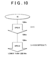
- the HPS 13 is able to exhibit its assisting ability to the fullest extent when the output torque of 100 Nm is applied to the HPS 13. Therefore, in a comparative example in FIG. 10 , the assist of 1000 Nm is not obtained unlike in the comparative example in FIG. 9 in which the EPS 12 is operating properly.
- the steering torque ⁇ of 100 Nm needs to be applied to the steering wheel 15 in order to allow the HPS 13 to exhibit its assisting ability to the fullest extent.
- it is difficult to allow the HPS 13 to exhibit its assisting ability to the fullest extent because the steering torque ⁇ required to obtain the steering assist from the HPS 13 is excessively high. That is, if the steering assist from the EPS 12 is stopped and thus the steering assist is provided only by the HPS 13, the driver's steering operation becomes considerably heavy, leading to a difficulty in smooth steering.
- the torsional stiffness of the torsion bar 54 of the HPS 13 is set to a low value that is substantially equal to the torsional stiffness of the torsion bar 21a of the EPS 12.
- the torsional stiffness of the torsion bar 54 is set to one-tenths of that in the comparative example illustrated in FIG. 9 .
- the torsion bar 54 in the present embodiment is twisted ten times as much as the torsion bar 54 in the comparative example illustrated in FIG. 9 .
- the HPS 13 is able to exhibit its assisting ability to the fullest extent even when the steering torque ⁇ of 10 Nm, which is the maximum steering torque that can be applied by an average driver, is applied to the steering wheel 15. Because the torsional stiffness of the torsion bar 54 is one-tenths of that in the comparative example, the HPS 13 amplifies the torque 100-fold, not 10-fold as in the comparative example. This is because the torsional stiffness of the torsion bar 54 is decreased and the torsion amount of the torsion bar 54 upon application of the same steering torque ⁇ is increased accordingly. The torsion amount of the torsion bar 54 is increased, and the opening degree of the control valve 61 is increased and the flow rate of the hydraulic fluid is increased accordingly. Thus, the steering torque ⁇ of 10 Nm, which is the output torque from the EPS 12, is amplified by the HPS 13 to 1000 Nm, which is 100 times as high as 10 Nm.
- the steering torque ⁇ that is required to allow the HPS 13 to exhibit its assisting ability to the fullest extent is substantially equal to that when the EPS 12 is operating properly. Further, it is possible to gain substantially the same steering feel as that when the EPS 12 is operating properly.
- the final assist amount achieved by the HPS 13 is 1000 Nm that is equal to the final assist amount achieved when the EPS 12 is operating properly in the comparative example illustrated in FIG. 9 .
- the steering torque ⁇ of 10 Nm that is applied to the steering wheel 15 is amplified 10-fold to 100 Nm.
- the torsional stiffness of the torsion bar 54 of the HPS 13 is set to a low value that is substantially equal to the torsional stiffness of the torsion bar 21a of the EPS 12.
- the opening degree of the control valve 61 is maximized and thus the HPS 13 exhibits its assisting ability to the fullest extent.
- the HPS 13 amplifies the output torque of 100 Nm from the EPS 12 100-fold to 10000 Nm, which is 100 times as high as 100 Nm.
- the total assist amount is excessive when the EPS 12 is operating properly.
- bypass pipe 36 and the electric valve 37 are provided in the present embodiment. At normal times, it is possible to limit the assisting ability of the HPS 13 by adjusting the opening degree of the electric valve 37. This is because it is possible to adjust the flow rate of the hydraulic fluid that is supplied to the HPS 13 based on the opening degree of the electric valve 37.
- the steering torque ⁇ of 10 Nm applied to the steering wheel 15 is amplified 10-fold to 100 Nm.
- the torsional stiffness of the torsion bar 54 of the HPS 13 is set to a low value that is substantially equal to the torsional stiffness of the torsion bar 21a of the EPS 12 as described above, the opening degree of the control valve 61 is maximized and thus the HPS 13 exhibits its assisting ability to the fullest extent.
- the assisting ability of the HPS 13 needs to be limited to one-tenths of that in the comparative example illustrated in FIG. 11 . That is, the opening degree of the electric valve 37 is adjusted such that 90% of the hydraulic fluid discharged from the pump 32 is returned to the reservoir tank 33 through the bypass pipe 36 and the remaining 10% of the hydraulic fluid is supplied to the HPS 13.
- the assisting ability of the HPS 13 limited to one-tenths of that in the comparative example in FIG. 11 as the flow rate of the hydraulic fluid supplied to the HPS 13 is limited to one-tenths of that in the comparative example illustrated in FIG. 11 .
- the HPS 13 amplifies the output torque of 100 Nm to 1000 Nm, which is not 100 times but 10 times as high as 100 Nm, as illustrated in FIG. 12 .
- the flow rate of the hydraulic fluid that is supplied to the HPS 13 through adjustment of the opening degree of the electric valve 37 as described above, it is possible to flexibly control the assist amount to be achieved by the HPS 13.
- the above-described embodiment may be modified as follows.
- the opening degree of the electric valve 37 may be adjusted continuously or may be adjusted in a stepwise manner.
- the target assist amount Tas* is computed based on the steering torque ⁇ and the vehicle speed V in the above-described embodiment.
- the target assist amount Tas* may be computed based on at least the steering torque ⁇ .
- the difference in pressure between the discharge pipe 34 and the drain pipe 35 is obtained with the use of the two pressure sensors 71, 72 in the above-described embodiment.
- a single differential pressure sensor may be disposed between the discharge pipe 34 and the drain pipe 35.
- the ECU 14 may be exclusive to the EPS 12. An additional ECU that controls the electric valve 37 may be provided, or an ECU of another vehicle system may also control the electric valve 37.
- the two pressure sensors 71, 72 may be omitted. In this case, the control of the electric valve 37 is executed according to the above-described method (A) in which the pressure sensors 71, 72 are not used.
- a malfunction of the HPS 13 is detected according to a method in which the pressure sensors 71, 72 are not used.
- the ECU 14 determines that a malfunction has occurred in the HPS 13, for example, when the steering assist is not executed although the driver's steering operation should be assisted by the HPS 13.
- the ECU 14 detects an output torque from the EPS 12 and thus an axial force acting in the axial direction of the steered wheels 43 by multiplying the motor current by the steering torque ⁇ (input torque).
- the ECU 14 computes a momentum of the vehicle such as a yaw rate based on the vehicle speed and the steering angle, and computes a total axial force that should be generated by the power steering system 11 based on the computed momentum of the vehicle.
- the ECU 14 determines whether an axial force is generated by the HPS 13 by comparing the total axial force that should be generated and the axial force generated by the EPS 12.
- the ECU 14 determines that a malfunction has occurred in the HPS 13 when the axial force generated by the EPS 12 is smaller than the total axial force that should be generated by the power steering system 11 although the axial force generated by the EPS 12 exhibits a value corresponding to the critical power of the EPS 12. In this way, it is possible to determine whether the HPS 13 assists the driver's steering operation while the vehicle is travelling, without providing the pressure sensors 71, 72.
- bypass pipe 36 that connects the high pressure-side discharge pipe 34 and the low pressure-side drain pipe 35 to each other and the electric valve 37 that opens or closes the bypass pipe 36.
- the bypass pipe 36 and the electric valve 37 may be adopted. With this configuration, even when the EPS 12 malfunctions, it is possible to gain the steering feel similar to that when the EPS 12 is operating properly.
- the RBS-type steering mechanism is adopted in the above-described embodiment.
- a rack-and-pinion-type steering mechanism may be adopted.
- the rack-and-pinion mechanism changes the orientation of the wheels by converting the rotation of a pinion shaft linked to the steering wheel 15 into a linear motion of a rack shaft meshed with the pinion shaft.
- the HPS 13 assists the driver's steering operation by assisting the operation of the rack shaft. That is, an assist force is generated by introducing the hydraulic fluid supplied from the pump 32 via the control valve 61 to a power cylinder disposed coaxially with the rack shaft.
- the input shaft 52 for the control valve 61 and the pinion shaft are connected to each other via the torsion bar 54.
- the flow rate of the hydraulic fluid that is supplied to the power cylinder is adjusted based on the valve operating angle, which is the difference between the rotation angle of the input shaft 52 and the rotation angle of the pinion shaft.
Abstract
Description
- The invention relates to a power steering system.
- There is a conventional power steering system including both an electric steering assist device that uses a motor as a power source and a hydraulic steering assist device that uses an internal combustion engine, which serves as a vehicle axle driving source, as a power source, in order to apply assist torque to a steering system of a vehicle, as described in, for example, Japanese Patent No.
5034446 - The electric steering assist device is a column assist-type steering assist device. The electric steering assist device produces output torque by adding assist torque, which is generated by the motor, to input torque, which is input into a steering wheel, and then applies the output torque to the hydraulic steering assist device. The hydraulic steering assist device is a rack-and-pinion-type steering assist device including a rotary control valve. Upon application of the output torque from the electric steering assist device, the control valve is operated. Through the operation of the control valve, the flow path and the flow rate of hydraulic fluid that is supplied from a hydraulic pump to a power cylinder disposed in a rack body are switched based on a torsion angle of a torsion bar incorporated in the control valve. The power cylinder generates a rack driving force (steering assist force) as the hydraulic fluid is supplied to a cylinder chamber for right steering assist or a cylinder chamber for left steering assist. A solenoid relief valve is disposed between a high-pressure flow path that leads to the hydraulic pump and a low-pressure flow path that leads to a reservoir tank.
- At normal times, the electric steering assist device does not generate assist torque using the motor when the input torque is lower than a set value. That is, the input torque is used as it is, as the output torque from the electric steering assist device. Assist torque corresponding to the output torque is generated by the hydraulic steering assist device until the output torque reaches the set value. After the output torque reaches the set value, the electric steering assist device starts generating assist torque, while the solenoid relief valve is opened and thus part of the hydraulic fluid is returned to the reservoir tank, so that the assist torque that is generated by the hydraulic steering assist device is limited. In this case, the output torque produced by the electric steering assist device is a value that is obtained by adding the assist torque generated by the motor to the input torque input into the steering wheel.
- If one of the electric steering assist device and the hydraulic steering assist device malfunctions, steering assist is continued by the other one of the hydraulic steering assist device and the electric steering assist device, which is operating properly. If the electric steering assist device malfunctions, a set valve opening pressure, at which the solenoid relief valve is opened, is changed to a value higher than that used at normal times. Because it is possible to increase the flow rate of the hydraulic fluid that is supplied to the power cylinder to a flow rate higher than that used at normal times, the hydraulic steering assist device is able to generate assist torque corresponding to the torque applied to the hydraulic steering assist device not only when the torque applied to the hydraulic steering assist device is lower than the set value but also when the torque applied thereto is equal to or higher than the set value. That is, if the electric steering assist device malfunctions, a shortfall in the assist torque due to the malfunctioning is covered by the steering assist force generated the hydraulic steering assist device.
- If the hydraulic steering assist device malfunctions, the electric steering assist device generates assist torque using the motor even when the input torque input into the steering wheel is lower than the set value.
- In the power steering system according to Japanese Patent No.
5034446 - One object of the invention is to provide a power steering system that provides, even if an electric power steering malfunctions, a steering feel similar to that before occurrence of the malfunction.
- A power steering system according to an aspect of the invention includes: an electric power steering including a motor serving as an electric actuator that generates a first steering assist force based on a torsion amount of a first torsion bar to which steering torque is applied; and a hydraulic power steering including a hydraulic actuator that generates a second steering assist force based on a flow rate of a hydraulic fluid supplied from a pump that operates using an internal combustion engine as a driving source, and a control valve that controls supply of the hydraulic fluid to the hydraulic actuator and drain of the hydraulic fluid from the hydraulic actuator based on a torsion amount of a second torsion bar to which the steering torque and the first steering assist force are applied. The second torsion bar has a torsional stiffness that is equal to or substantially equal to a torsional stiffness of the first torsion bar.
- In this configuration, the torsional stiffness of the second torsion bar is equal to or substantially equal to the torsional stiffness of the first torsion bar. That is, when the same degree of torque is applied to each of the first torsion bar and the second torsion bar, the torsion amount of the first torsion bar and the torsion amount of the second torsion bar are equal to or substantially equal to each other. When the electric power steering malfunctions, the steering torque is applied as it is, to the second torsion bar via the first torsion bar. Thus, even if the electric power steering malfunctions, it is possible to gain the steering feel similar to that when the electric power steering is operating properly.
- When the electric power steering is operating properly, the first steering assist force generated by the electric power steering in addition to the steering torque is applied to the second torsion bar. That is, the second torsion bar is supplied with a torque higher than the torque that is applied to the second torsion bar when the electric power steering malfunctions. The torsion amount of the second torsion bar is significantly increased, and thus the hydraulic actuator may be supplied with the hydraulic fluid at the maximum flow rate in the control valve.
- In order to avoid such a possibility, the power steering system according to the above aspect may further include: an electric valve that provides or interrupts communication between a supply path through which the hydraulic fluid is supplied to the control valve and a drain path through which the hydraulic fluid is drained from the control valve; and a controller that adjusts the flow rate of the hydraulic fluid that is supplied to the control valve by controlling an opening degree of the electric valve.
- With this configuration, it is possible to appropriately adjust the magnitude of the second steering assist force generated by the hydraulic actuator, by controlling the flow rate of the hydraulic fluid that is supplied to the control valve and then to the hydraulic actuator through adjustment of the opening degree of the electric valve. As the opening degree of the electric valve is increased, the flow rate of the hydraulic fluid that is diverted to the drain path, out of the hydraulic fluid discharged from the pump, is increased, and thus the flow rate of the hydraulic fluid that is supplied to the control valve is decreased.
- In the power steering system according to the aspect, the controller may be configured to fully close the electric valve when the electric power steering malfunctions. With this configuration, the hydraulic fluid discharged from the pump is entirely supplied to the control valve. The control valve supplies the hydraulic actuator with the hydraulic fluid at the flow rate corresponding to the torsion amount of the second torsion bar caused upon application of the steering torque. Thus, it is possible to utilize the steering ability of the hydraulic power steering to the fullest extent.
- In the power steering system according to the above aspect, the controller may be configured to fully open the electric valve when the hydraulic power steering malfunctions. There are various factors of a malfunction of the hydraulic power steering. There may be situations where it is not desirable that the hydraulic fluid flow from the pump side toward the control valve. However, by fully opening the electric valve, the hydraulic fluid discharged from the pump is introduced to the drain path via the electric valve. Therefore, it is possible to restrain the hydraulic fluid discharged from the pump from being supplied to the control valve.
- In the power steering system according to the above aspect, the controller may serve as a controller for the motor. In the power steering system according to the above aspect, the controller may compute a required steering assist force based on the steering torque, and the controller may control the opening degree of the electric valve in the following manner. Until the required steering assist force reaches a maximum steering assist force that the electric power steering is able to generate, the steering assist force is generated only by the electric power steering. When the required steering assist force exceeds the maximum steering assist force that the electric power steering is able to generate, a steering assist force corresponding to a shortfall in the steering assist force generated by the electric power steering is generated by the hydraulic power steering.
- With this configuration, by giving a higher priority to the electric power steering than to the hydraulic power steering when they are used, the load on the engine is reduced accordingly.
- The foregoing and further features and advantages of the invention will become apparent from the following description of example embodiments with reference to the accompanying drawings, wherein like numerals are used to represent like elements and wherein:
-
FIG. 1 is a configuration diagram illustrating the schematic configuration of a power steering system according to an embodiment of the invention; -
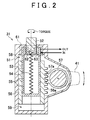
FIG. 2 is a view schematically illustrating the configuration of a steering gearbox in the embodiment; -
FIG. 3 is a graph illustrating the relationship between the input torque and the deformation amount of a torsion bar in the embodiment; -
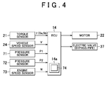
FIG. 4 is a block diagram illustrating the electrical configuration of the power steering system according to the embodiment; -
FIG. 5 is a graph illustrating an assist map in the embodiment; -
FIG. 6 is a graph illustrating the ratio between the assist amount achieved by an electric power steering and the assist amount achieved by a hydraulic power steering at normal times according to the embodiment; -
FIG. 7 is a graph illustrating variations of the assist amount achieved by the hydraulic power steering with respect to the input torque when the electric power steering malfunctions in the embodiment; -
FIG. 8 is a graph illustrating variations of the assist amount achieved by the electric power steering with respect to the input torque when the hydraulic power steering malfunctions in the embodiment; -
FIG. 9 is a conceptual diagram illustrating the concept of steering assist provided by the electric power steering and the hydraulic power steering at normal times in a comparative example; -
FIG. 10 is a conceptual diagram illustrating the concept of steering assist provided by the electric power steering and the hydraulic power steering when the electric power steering malfunctions in a comparative example; -
FIG. 11 is a conceptual diagram illustrating the concept of steering assist provided by the electric power steering and the hydraulic power steering at normal times in a comparative example; and -
FIG. 12 is a conceptual diagram illustrating the concept of steering assist provided by the electric power steering and the hydraulic power steering at normal times in the embodiment. - Hereinafter, a
power steering system 11 of a vehicle according to an embodiment of the invention will be described. As illustrated inFIG. 1 , thepower steering system 11 includes an electric power steering (EPS) 12, a hydraulic power steering (HPS) 13, and an electronic control unit (ECU) 14. - The
EPS 12 is disposed on an intermediate portion of a steeringshaft 16 to which asteering wheel 15 is connected. TheEPS 12 includes atorque sensor 21, amotor 22, and aspeed reducer 23. - The
torque sensor 21 includes atorsion bar 21a disposed at an intermediate portion of the steeringshaft 16, and twosensor elements torsion bar 21a. Thetorsion bar 21a is twisted when steering torque is applied to thetorsion bar 21a by a driver via thesteering wheel 15. The twosensor elements torsion bar 21a. - The
motor 22 is connected to the steeringshaft 16 via thespeed reducer 23. Thespeed reducer 23 reduces the speed of rotation output from themotor 22, and transmits the torque, which is output from the motor and then amplified due to reduction in the rotation speed, to the steeringshaft 16. That is, the torque generated by themotor 22 is applied to the steeringshaft 16 as a steering assist force, so that the driver's operation of thesteering wheel 15 is assisted. - The
ECU 14 acquires results of detection by various sensors disposed in the vehicle as information indicating a command from the driver or a travelling state, and controls themotor 22 based on the acquired various information. Examples of the various sensors include, in addition to thetorque sensor 21, avehicle speed sensor 24 that detects a vehicle speed V that is a travelling speed of the vehicle. TheECU 14 detects a steering torque τ based on the electrical signals Sa, Sb generated by the twosensor elements ECU 14 computes a target assist force, which is a target assist amount, based on the steering torque τ and the vehicle speed V, and then supplies themotor 22 with driving electric power used to generate the target assist force. - The
HPS 13 is disposed at an end portion of the steeringshaft 16, the end portion being on the opposite side of the steeringshaft 16 from thesteering wheel 15. TheHPS 13 includes a recirculating ball screw-type (RBS-type)steering gear box 31, apump 32, and areservoir tank 33. A pump port of thesteering gear box 31 is connected to thepump 32 through adischarge pipe 34. A tank port of thesteering gear box 31 is connected to thereservoir tank 33 through adrain pipe 35. Thedischarge pipe 34 and thedrain pipe 35 are connected to each other by a bypass pipe 36. The bypass pipe 36 is provided with anelectric valve 37. - The
steering gear box 31 converts the rotary motion of the steeringshaft 16 into a right-left oscillating motion of apitman arm 41. The oscillation of thepitman arm 41 is transmitted to right and left steeredwheels 43 via right and lefttie rods 42. Thepump 32 is driven by anengine 44. As thepump 32 is driven, hydraulic fluid in thereservoir tank 33 is supplied to thesteering gear box 31 through thedischarge pipe 34. The hydraulic fluid drained from thesteering gear box 31 is returned to thereservoir tank 33 through thedrain pipe 35. The opening degree of theelectric valve 37 is controlled by theECU 14. As the opening degree of theelectric valve 37 is increased, the flow rate of the hydraulic fluid that is diverted to thedrain pipe 35, out of the hydraulic fluid discharged from thepump 32, is increased. - As illustrated in
FIG. 2 , aninput shaft 52, ahollow ball screw 53, atorsion bar 54,multiple balls 55, aball nut 56, and asector shaft 57 are disposed in ahousing 51 of thesteering gear box 31. - The
input shaft 52 passes through an upper wall of thehousing 51, and is supported so as to be rotatable relative to thehousing 51. An outer end of theinput shaft 52 is inserted in the steeringshaft 16 so as to be rotatable relative to the steeringshaft 16, and an inner end of theinput shaft 52 is inserted in theball screw 53 so as to be rotatable relative to theball screw 53. The inner end of theinput shaft 52 and an inner bottom face of theball screw 53 are connected to each other by thetorsion bar 54 disposed therebetween. The ball screw 53 is screwed to theball nut 56 via the multiple circulatingballs 55. Theball nut 56 is disposed so as to be slidable relative to a cylinder portion of thehousing 51 in a direction along the axis of theball nut 56.Rack teeth 56a are formed on an outer peripheral face of theball nut 56 over a certain range in the axial direction of theball nut 56. Therack teeth 56a are meshed with asector gear 57a formed on thesector shaft 57 that is orthogonal to the axis of theball nut 56. One end portion of thesector shaft 57 protrudes outside thehousing 51, and the one end portion is provided with thepitman arm 41 such that thepitman arm 41 and thesector shaft 57 are rotatable together with each other. The right and lefttie rods 42 are connected to thepitman arm 41. - The rotation of the
steering wheel 15 is transmitted to theball screw 53 via theinput shaft 52 and thetorsion bar 54. As theball nut 56 is moved in its axial direction due to the rotation of theball screw 53, thesector shaft 57 and thus thepitman arm 41 are oscillated from side to side via thesector gear 57a meshed with therack teeth 56a. - The internal space of the
housing 51 is partitioned into twooil chambers ball nut 56. The twooil chambers ball nut 56 interposed therebetween in the axial direction of theball nut 56. Theoil chamber 58 is located in an upper portion of thehousing 51 inFIG. 2 and theoil chamber 59 is located in a lower portion of thehousing 51 inFIG. 2 . The hydraulic fluid is supplied to the twooil chambers control valve 61 disposed in thehousing 51. As the hydraulic fluid from thepump 32 is supplied to one of the twooil chambers control valve 61, a difference in pressure between the twooil chambers ball nut 56 functions as a piston in response to the pressure difference and is pressed along the axial direction of theball nut 56, an assist force based on the hydraulic pressure is applied to the tie rod 42 (steering mechanism) via thesector shaft 57 and thepitman arm 41. - Upon application of torque to the
input shaft 52, theinput shaft 52 rotates. Thecontrol valve 61 is a rotary valve that controls supply or drain of the hydraulic fluid to or from the twooil chambers input shaft 52, that is, the rotation of theinput shaft 52. When theinput shaft 52 rotates clockwise relative to theball screw 53, thepump 32 and theoil chamber 58 communicate with each other. When theinput shaft 52 rotates counterclockwise relative to theball screw 53, thepump 32 and theoil chamber 59 communicate with each other. - The
control valve 61 includes aninner valve 62 disposed on an outer periphery of theinput shaft 52, and anouter valve 63 disposed on an inner periphery of theball screw 53. When frictional resistance between the steeredwheels 43 and a road surface is greater than the torque applied to theinput shaft 52, theball screw 53 does not rotate and thetorsion bar 54 is twisted based on the torque applied to theinput shaft 52. As thetorsion bar 54 is twisted, the positional relationship (relative angle) between theinner valve 62 and theouter valve 63 in the rotational direction is changed. Thecontrol valve 61 switches the flow path of the hydraulic fluid on the basis of a change in the positional relationship. Thecontrol valve 61 adjusts the flow passage area based on the difference (valve operating angle) between the rotation angle of the input shaft 52 (inner valve 62) and the rotation angle of the ball screw 53 (outer valve 63), thereby adjusting the flow rate of the hydraulic fluid that is supplied to theoil chambers discharge pipe 34 from thepump 32 is diverted to one of the twooil chambers inner valve 62 and theouter valve 63. The hydraulic fluid in the other one of theoil chambers oil chambers ball nut 56 is axially displaced in a direction away from the one of theoil chambers pump 32. The hydraulic fluid pushed out of the other one of theoil chambers reservoir tank 33 via thedrain pipe 35. - Next, the
torsion bars torsion bar 21a of thetorque sensor 21 is twisted as the steering torque is applied to thesteering wheel 15. Because a moderate reaction force (response) needs to be generated in response to an operation of thesteering wheel 15, the torsion of thetorsion bar 21a of thetorque sensor 21 is used as the reaction force in thepower steering system 11 to obtain the responsive feel. The responsive feel gained in response to the operation of thesteering wheel 15, that is, so-called heaviness of steering, is generated by thetorsion bar 21a. When the surface resistance is high, thetorsion bar 21a is largely twisted to generate a high reaction force. On the other hand, when the surface resistance is low, the torsion angle is small and the reaction force is also small. - The
torsion bar 54 of thesteering gear box 31 is twisted as the output torque from theEPS 12, which contains the steering torque, is applied to theinput shaft 52. Therefore, the torsional stiffness (spring constant) of thetorsion bar 54 is usually set higher than that of thetorsion bar 21a of thetorque sensor 21. This is because the output torque from theEPS 12 is a value obtained by adding the assist force generated by themotor 22 to the steering torque applied to thesteering wheel 15, and is a value higher than the steering torque. Therefore, in order to cause theEPS 13 to generate an appropriate assist force corresponding to a steering operation performed by the driver, the output torque from theEPS 12 needs to be taken into account to set the torsional stiffness of thetorsion bar 54. - As illustrated in a graph in
FIG. 3 , the torsional stiffness of the torsion bar (TB) 54 is set substantially equal to the torsional stiffness of the torsion bar (TB) 21a in the present embodiment. "The torsional stiffness of the torsion bar (TB) 54 is substantially equal to the torsional stiffness of the torsion bar (TB) 21a" means not only that the twotorsion bars FIG. 3 but also that the torsional stiffness of the torsion bar (TB) 54 is slightly higher than the torsional stiffness of thetorsion bar 21a (indicated by a two-dot chain line above the continuous line) and the torsional stiffness of the torsion bar (TB) 54 is slightly lower than the torsional stiffness of thetorsion bar 21a (indicated by a two-dot chain line below the continuous line) as indicated by two-dot chain lines in the graph inFIG. 3 . Therefore, when the same magnitude of torque is applied to second ends of thetorsion bars torsion bars torsion bars torsion bar 21a of thetorque sensor 21 is set on the basis of the steering torque τ applied to thesteering wheel 15 by the driver. When the steering torque τ generated by the driver's steering operation is 10 Nm at the maximum, each of the twotorsion bars torsion bar 54 of theHPS 13 substantially equal to the torsional stiffness of thetorsion bar 21a of theEPS 12 as described above, it is possible to operate thecontrol valve 61 through the steering operation by the driver even if the assist force from theEPS 12 is not obtained. - The electrical configuration of the
power steering system 11 will be described below. As illustrated inFIG. 4 , thetorque sensor 21, thevehicle speed sensor 24, twopressure sensors engine speed sensor 73 are connected to theECU 14. Themotor 22 and theelectric valve 37 are connected to theECU 14. Thepressure sensor 71 detects a pressure in the discharge pipe (high-pressure pipe) 34 and thepressure sensor 72 detects a pressure in the drain pipe (low-pressure pipe) 35. Theengine speed sensor 73 detects a rotational speed of theengine 44. - The
ECU 14 computes a target assist torque, which is the target assist amount, based on the results of detection obtained by thetorque sensor 21 and thevehicle speed sensor 24, that is, the steering torque τ (more specifically, the two electrical signals Sa, Sb) and the vehicle speed V. TheECU 14 computes an appropriate target assist amount corresponding to the present vehicle state on the basis of anassist map 74, stored in amemory 14a of theECU 14. - As illustrated in
FIG. 5 , theassist map 74 is a vehicle speed-sensitive three-dimensional map for computing a target assist amount Tas* based on the steering torque τ and the vehicle speed V. According to the assistmap 74, the target assist amount Tas* having a larger value (absolute value) is computed as the absolute value of the steering torque τ is higher and as the vehicle speed V is lower, so that a larger assist force is applied to a steering system. - The target assist amount Tas* computed based on the
assist map 74 is the total assist amount that is the sum of the assist amount achieved by the EPS 12 (the amount of assist provided by the EPS 12) and the assist amount achieved by the HPS 13 (the amount of assist provided by the EPS 13). TheECU 14 controls themotor 22 and theelectric valve 37 such that the target assist amount Tas* is obtained as a whole, while adjusting the assist amount to be achieved by theEPS 12 and the assist amount to be achieved by theHPS 13 as needed based on results of output from the various sensors. - The
ECU 14 computes a target EPS assist amount Tas1* and a target HPS assist amount Tas2* based on the target assist amount Tas* and the steering torque τ. The target EPS assist amount Tas1* is an assist amount that is contained in the target assist amount Tas* and that should be achieved by theEPS 12. The target HPS assist amount Tas2* is an assist amount that is contained in the target assist amount Tas* and that should be generated by theHPS 13. Theoretically, the following equation (1) is satisfied.
- The
ECU 14 controls the assist amount to be achieved by theEPS 12 by adjusting the amount of currents supplied to themotor 22, and controls the assist amount to be achieved by theHPS 13 by adjusting the opening degree of theelectric valve 37. - In the present embodiment, the driver's steering operation is assisted mainly by the
EPS 12 as much as possible from the viewpoint of energy saving. If the diver's steering operation is not assisted sufficiently even when the maximum ability of theEPS 12 is fully utilized, theelectric valve 37 disposed in the bypass pipe 36 is gradually closed based on a shortfall in the assist amount to increase the assist amount to be achieved by theHPS 13. Thepump 32 is driven by theengine 44. Therefore, when the driver's steering operation is assisted by the HPS 13a, an extra load is placed on theengine 44 accordingly. Therefore, in the case where the required assist amount is small, as in the case where the vehicle is travelling at a high speed, the driver's steering operation should be assisted only by theEPS 12 without using theHPS 13. In this case, the fuel consumption is smaller and the amount of energy saving is larger than those in the case where a load due to the steering assist is maintained constantly placed on theengine 44. - The
ECU 14 controls theelectric valve 37 according to one of the following methods (A) and (B). - (A) The
ECU 14 determines a target opening degree of theelectric valve 37 based on an engine speed N and the target HPS assist amount Tas2*, and controls theelectric valve 37 to achieve the target opening degree. - (B) The
ECU 14 determines a target pressure difference between the pressure in the high pressure-side discharge pipe 34 and the pressure in the low pressure-side drain pipe 35 based on the engine speed N and the target HPS assist amount Tas2*, and executes feedback control on theelectric valve 37 to make the difference between pressures P1, P2, which are respectively detected by the twopressure sensors - The rotational speed of the
pump 32 is determined by the rotational speed of theengine 44. Thus, the flow rate of the hydraulic fluid that is supplied to theHPS 13 is determined basically according to the rotational speed of theengine 44. Therefore, it is possible to adjust the flow rate of the hydraulic fluid that is supplied to theHPS 13 by adjusting the opening degree of theelectric valve 37 in the present embodiment. When theelectric valve 37 is fully closed, most of the hydraulic fluid from thepump 32 is supplied to theHPS 13. At this time, theHPS 13 is able to exhibit its assisting ability to the fullest extent. However, the assist amount achieved by theHPS 13 is influenced by the rotational speed of theengine 44. On the other hand, when theelectric valve 37 is fully open, most of the hydraulic fluid from thepump 32 flows to thedrain pipe 35 through the bypass pipe 36, and thus almost no hydraulic fluid is supplied to theHPS 13. At this time, almost no steering assist is provided by theHPS 13. By changing the flow rate of the hydraulic fluid that is supplied to theHPS 13 on the basis of the opening degree of theelectric valve 37 in this way, it is possible to control the assist amount achieved by theHPS 13. - The
ECU 14 has a function of detecting malfunctions of theEPS 12 and theHPS 13. TheECU 14 detects, for example, each of the following conditions (C), (D) as a malfunction of theEPS 12. TheECU 14 fully closes theelectric valve 37 when a malfunction of theEPS 12 is detected. - (C) A malfunction of the torque sensor 21 (electrical signals Sa, Sb) is detected.
- When the values of the two electrical signals Sa, Sb deviate from values of the electrical signals Sa, Sb at normal times, the electrical signals Sa, Sb that deviate from the normal values are abnormal.
- When the values of the two electrical signals Sa, Sb or the amounts of change in the two electrical signals Sa, Sb per unit time are not equal to each other, at least one of the two electrical signals Sa, Sb is abnormal.
- (D) A malfunction of the
motor 22 is detected. - The
ECU 14 controls the power supply to themotor 22 through pulse width modulation (PWM) using a motor driver (PWM inverter (not illustrated)). TheECU 14 detects a current that is supplied to themotor 22 using a current sensor (not illustrated). When the value of current supplied to themotor 22 is zero despite the fact that the duty ratio of a PWM control signal for the motor driver is set at 100%, a malfunction such as disconnection occurs in themotor 22 or a power supply path to themotor 22 - The
ECU 14 detects, for example, the following condition (E) as a malfunction of theHPS 13. TheECU 14 fully opens theelectric valve 37 disposed in the bypass pipe 36 when a malfunction of theHPS 13 is detected. - (E) When the difference between the pressure in the
discharge pipe 34, which is detected by the high pressure-side pressure sensor 71, and the pressure in thedrain pipe 35, which is detected by the low pressure-side pressure sensor 72, falls out off a prescribed normal range, there is a possibility that thepump 32 is not operating properly. - The operation of the
power steering system 11 will be described below. First, the operation of thepower steering system 11 when both theEPS 12 and theHPS 13 are operating properly will be described. - The
ECU 14 executes control in the following manner. The driver's steering operation is assisted only by theEPS 12 until the required assist amount (target assist amount Tas*) reaches the critical power of the EPS 12 (the maximum assist amount achievable by the EPS 12). When the required assist amount cannot be achieved only by theEPS 12, the assist amount achieved by theHPS 13 is added to the assist amount achieved by theEPS 12 on the basis of a shortfall in the required assist amount. - As illustrated in a graph in
FIG. 6 , theECU 14 executes control such that the driver's steering operation is assisted only by theEPS 12 until the input torque (steering torque τ) reaches a threshold τ1. The threshold τ1 is set based on the critical power of theEPS 12. That is, the total assist amount that is required when the input torque reaches the threshold τ1 is a maximum assist amount Te-max that is able to be generated by theEPS 12. - The
ECU 14 keeps theelectric valve 37 fully open until the input torque reaches the threshold τ1. Because most of the hydraulic fluid from thepump 32 is returned to thereservoir tank 33 through the bypass pipe 36, almost no hydraulic fluid is supplied to theHPS 13. Therefore, the assist amount achieved by theHPS 13 is a value close to zero. After the input torque reaches the threshold τ1, theECU 14 gradually decreases the opening degree of theelectric valve 37 based on an increase in the input torque. As the opening degree of theelectric valve 37 is decreased, the flow rate of the hydraulic fluid that is supplied to theHPS 13 increases. The assist amount achieved by theHPS 13 is increased with an increase in the flow rate of the hydraulic fluid. A total assist amount Tas is gradually increased with an increase in the assist amount achieved by theHPS 13, as the assist amount achieved by theHPS 13 is added to the assist amount achieved by theEPS 12. - The assist torque generated by the
EPS 12, in addition to the steering torque τ applied to thesteering wheel 15 by the driver, is applied to theinput shaft 52 for theHPS 13. Thetorsion bar 54 of thecontrol valve 61 has a torsional stiffness substantially equal to the torsional stiffness of thetorsion bar 21a of theEPS 12. That is, the torsional stiffness of thetorsion bar 54 is set such that thetorsion bar 54 is sufficiently twisted by the steering torque τ applied by the driver. Thus, thecontrol valve 61 is substantially fully open when the steering torque τ and the assist torque generated by theEPS 12 are both applied to theinput shaft 52 for thecontrol valve 61. Therefore, the assist amount to be achieved by theHPS 13 is adjusted by adjusting the opening degree of theelectric valve 37. - The operation of the
power steering system 11 when a malfunction occurs in theEPS 12 will be described below. - When a malfunction occurs in the
EPS 12, the assist amount achieved by theEPS 12 is zero. The assist amount achieved by theHPS 13 is used as it is, as the total assist amount Tas. TheECU 14 keeps theelectric valve 37 fully closed. Thus, the hydraulic fluid from thepump 32 is entirely supplied to theHPS 13. Thetorsion bar 54 is twisted based on the input torque (steering torque τ, in this case) input into theinput shaft 52 for thecontrol valve 61, so that the opening degree of thecontrol valve 61 is changed based on the degree of torsion of thetorsion bar 54. The hydraulic fluid with a flow rate corresponding to the opening degree is supplied to theoil chamber 58 or theoil chamber 59. TheHPS 13 generates an assist force corresponding to the flow rate of the hydraulic fluid supplied to theoil chamber engine 44 at the present moment. - As illustrated in a graph in
FIG. 7 , the assist amount achieved by theHPS 13 increases with an increase in the input torque. After the input torque reaches a threshold τ2 (> τ1), the assist amount achieved by theHPS 13 is maintained constant regardless of the input torque. That is, after the input torque reaches the threshold τ2, the originally required total assist amount reaches the maximum assist amount Th-max that is achievable by theHPS 13. The threshold τ2 is determined by the critical power of theHPS 13. - Although the assist torque by the
EPS 12 is not obtained, the steering feel gained by the driver is similar to that when theEPS 12 is operating properly. When theEPS 12 malfunctions, the responsive feel gained in response to the operation of thesteering wheel 15 depends on not only thetorsion bar 21a but also thetorsion bar 54. In the present embodiment, the torsional stiffness of thetorsion bar 54 is set substantially the same as the torsional stiffness of thetorsion bar 21a, and thus the steering feel gained by the driver is similar to that when theEPS 12 is operating properly. - The operation of the
power steering system 11 when a malfunction occurs in theHPS 13 will be described below. - When a malfunction occurs in the
HPS 13, the assist amount achieved by theHPS 13 is zero. The assist amount achieved by theEPS 12 is used as it is, as the total assist amount Tas. TheECU 14 generates the assist torque corresponding to the input torque (steering torque τ, in this case) through the control of themotor 22. - As illustrated in a graph in
FIG. 8 , until the input torque reaches the threshold τ1 corresponding to the critical power of theEPS 12, the assist amount achieved by theEPS 12 increases with an increase in the input torque. After the input torque reaches the threshold τ1, the assist amount achieved by theEPS 12 is maintained constant regardless of the input torque. That is, after the input torque reaches the threshold τ1, the originally required total assist amount reaches the maximum assist amount Te-max that is achievable by theEPS 12. - When a malfunction occurs in the
HPS 13, theECU 14 keeps theelectric valve 37 fully open for the following reason. There are various factors of a malfunction of theHPS 13. For example, a malfunction may occur in thecontrol valve 61 although thepump 32 is operating properly. The following description will be provided on the assumption that thetorsion bar 54 is stuck twisted in one direction (becomes immovable after being twisted in one direction). In this case, the hydraulic fluid is supplied to only one of the twooil chambers oil chamber electric valve 37 is closed. However, if theelectric valve 37 is open, the hydraulic fluid from thepump 32 is returned to thereservoir tank 33 through the bypass pipe 36. In this way, it is possible to prevent an excessive increase in the pressure in theoil chamber - Next, the action of the
power steering system 11 will be described. First, a power steering system as a comparative example will be described below. In this comparative example, the bypass pipe 36 and theelectric valve 37 are not provided. For convenience of description, the vehicle speed V is not taken into account in this comparative example. - In the comparative example illustrated in
FIG. 9 , the torsional stiffness of thetorsion bar 54 is sufficiently higher than the torsional stiffness of thetorsion bar 21a. The maximum steering torque τ generated by an average driver is 10 Nm. TheEPS 12 includes thetorsion bar 21a having such a degree of stiffness that thetorsion bar 21a is sufficiently twisted when the steering torque τ of 10 Nm is applied to thesteering wheel 15, and theEPS 12 is able to exhibit its assisting ability to the fullest extent when the steering torque τ of 10 Nm is applied to thesteering wheel 15. TheEPS 12 amplifies the steering torque τ to, for example, 100 Nm, which is ten times as high as the steering torque τ of 10 Nm. - The
HPS 13 includes thetorsion bar 54 having such a degree of stiffness that thetorsion bar 54 is sufficiently twisted when the output torque of 100 Nm, which is the critical power of theEPS 12, is applied to theHPS 13, and theHPS 13 is able to exhibit its assisting ability to the fullest extent when the output torque of 100 Nm is applied to theHPS 13. TheHPS 13 amplifies the output torque of 100 Nm from theEPS 12 to, for example, 1000 Nm, which is ten times as high as the output torque of 100 Nm. -
FIG. 9 illustrates the comparative example in which theEPS 12 is operating properly. On the other hand, if a malfunction occurs in theEPS 12 and an assist force from theEPS 12 is not obtained as illustrated inFIG. 10 , the steering torque τ of 10 Nm applied by the driver is used as it is, as the output torque from theEPS 12. TheHPS 13 is able to exhibit its assisting ability to the fullest extent when the output torque of 100 Nm is applied to theHPS 13. Therefore, in a comparative example inFIG. 10 , the assist of 1000 Nm is not obtained unlike in the comparative example inFIG. 9 in which theEPS 12 is operating properly. - When a malfunction occurs in the
EPS 12 and the assist force from theEPS 12 is not obtained, the steering torque τ of 100 Nm needs to be applied to thesteering wheel 15 in order to allow theHPS 13 to exhibit its assisting ability to the fullest extent. However, it is difficult to allow theHPS 13 to exhibit its assisting ability to the fullest extent, because the steering torque τ required to obtain the steering assist from theHPS 13 is excessively high. That is, if the steering assist from theEPS 12 is stopped and thus the steering assist is provided only by theHPS 13, the driver's steering operation becomes considerably heavy, leading to a difficulty in smooth steering. - In the present embodiment, the following configuration is adopted to obtain the steering feel similar to that at normal times even if the
EPS 12 malfunctions. The torsional stiffness of thetorsion bar 54 of theHPS 13 is set to a low value that is substantially equal to the torsional stiffness of thetorsion bar 21a of theEPS 12. The torsional stiffness of thetorsion bar 54 is set to one-tenths of that in the comparative example illustrated inFIG. 9 . Thetorsion bar 54 in the present embodiment is twisted ten times as much as thetorsion bar 54 in the comparative example illustrated inFIG. 9 . Thus, theHPS 13 is able to exhibit its assisting ability to the fullest extent even when the steering torque τ of 10 Nm, which is the maximum steering torque that can be applied by an average driver, is applied to thesteering wheel 15. Because the torsional stiffness of thetorsion bar 54 is one-tenths of that in the comparative example, theHPS 13 amplifies the torque 100-fold, not 10-fold as in the comparative example. This is because the torsional stiffness of thetorsion bar 54 is decreased and the torsion amount of thetorsion bar 54 upon application of the same steering torque τ is increased accordingly. The torsion amount of thetorsion bar 54 is increased, and the opening degree of thecontrol valve 61 is increased and the flow rate of the hydraulic fluid is increased accordingly. Thus, the steering torque τ of 10 Nm, which is the output torque from theEPS 12, is amplified by theHPS 13 to 1000 Nm, which is 100 times as high as 10 Nm. - As described above, even when the
EPS 12 malfunctions, the steering torque τ that is required to allow theHPS 13 to exhibit its assisting ability to the fullest extent is substantially equal to that when theEPS 12 is operating properly. Further, it is possible to gain substantially the same steering feel as that when theEPS 12 is operating properly. In addition, the final assist amount achieved by theHPS 13 is 1000 Nm that is equal to the final assist amount achieved when theEPS 12 is operating properly in the comparative example illustrated inFIG. 9 . - As described above, by setting the torsional stiffness of the
torsion bar 54 to a low value, an appropriate assist amount is achieved by theHPS 13 when theEPS 12 malfunctions. However, when theEPS 12 is operating properly, the following concerns may be raised. - As illustrated in
FIG. 11 , when theEPS 12 is operating properly, the steering torque τ of 10 Nm that is applied to thesteering wheel 15 is amplified 10-fold to 100 Nm. As described above, the torsional stiffness of thetorsion bar 54 of theHPS 13 is set to a low value that is substantially equal to the torsional stiffness of thetorsion bar 21a of theEPS 12. Thus, the opening degree of thecontrol valve 61 is maximized and thus theHPS 13 exhibits its assisting ability to the fullest extent. Thus, theHPS 13 amplifies the output torque of 100 Nm from theEPS 12 100-fold to 10000 Nm, which is 100 times as high as 100 Nm. As described above, the total assist amount is excessive when theEPS 12 is operating properly. - Therefore, the bypass pipe 36 and the
electric valve 37 are provided in the present embodiment. At normal times, it is possible to limit the assisting ability of theHPS 13 by adjusting the opening degree of theelectric valve 37. This is because it is possible to adjust the flow rate of the hydraulic fluid that is supplied to theHPS 13 based on the opening degree of theelectric valve 37. - As illustrated in
FIG. 12 , when theEPS 12 is operating properly, the steering torque τ of 10 Nm applied to thesteering wheel 15 is amplified 10-fold to 100 Nm. Because the torsional stiffness of thetorsion bar 54 of theHPS 13 is set to a low value that is substantially equal to the torsional stiffness of thetorsion bar 21a of theEPS 12 as described above, the opening degree of thecontrol valve 61 is maximized and thus theHPS 13 exhibits its assisting ability to the fullest extent. In order to obtain, as the final assist torque, the assist torque of 1000 Nm that equal to the assist torque obtained when theEPS 12 is operating properly in the comparative example illustrated inFIG. 9 , the assisting ability of theHPS 13 needs to be limited to one-tenths of that in the comparative example illustrated inFIG. 11 . That is, the opening degree of theelectric valve 37 is adjusted such that 90% of the hydraulic fluid discharged from thepump 32 is returned to thereservoir tank 33 through the bypass pipe 36 and the remaining 10% of the hydraulic fluid is supplied to theHPS 13. The assisting ability of theHPS 13 limited to one-tenths of that in the comparative example inFIG. 11 as the flow rate of the hydraulic fluid supplied to theHPS 13 is limited to one-tenths of that in the comparative example illustrated inFIG. 11 . Thus, theHPS 13 amplifies the output torque of 100 Nm to 1000 Nm, which is not 100 times but 10 times as high as 100 Nm, as illustrated inFIG. 12 . By controlling the flow rate of the hydraulic fluid that is supplied to theHPS 13 through adjustment of the opening degree of theelectric valve 37 as described above, it is possible to flexibly control the assist amount to be achieved by theHPS 13. - According to the present embodiment, it is possible to obtain the following advantageous effects.
- (1) The
power steering system 11 includes theEPS 12 and theHPS 13. Even if one of theEPS 12 and theHPS 13 malfunctions, it is possible to continue the steering assist with the use of the other one of theHPS 13 and theEPS 12, which is operating properly. - (2) The torsional stiffness of the
torsion bar 54 of theHPS 13 is substantially equal to the torsional stiffness of thetorsion bar 21a of theEPS 12. Thus, even if theEPS 12 malfunctions, it is possible to obtain substantially the same steering feel as that when theEPS 12 is operating properly. - (3) There are provided the bypass pipe 36 that connects the high pressure-
side discharge pipe 34 and the low pressure-side drain pipe 35 to each other, and theelectric valve 37 that opens or closes the bypass pipe 36. It is possible to control the assist amount to be achieved by theHPS 13 by adjusting the opening degree of theelectric valve 37. - (4) The
electric valve 37 is fully closed when theEPS 12 malfunctions. The assist amount that is supposed to be achieved by theEPS 12 is covered by allowing theHPS 13 to exhibit its assisting ability to the fullest extent. In this way, it is possible to minimize a shortfall in the total assist force. - (5) The
electric valve 37 is fully opened when theHPS 13 malfunctions. The flow of the hydraulic fluid may be hindered for some reason. In this case, an excessive pressure may be generated in, for example, theoil chamber pump 32. However, the hydraulic fluid from thepump 32 is returned to thereservoir tank 33 through the bypass pipe 36 by fully opening theelectric valve 37. Thus, it is possible to suppress generation of an excessive pressure in, for example, theoil chambers - (6) The
electric valve 37 is controlled by theECU 14 that controls theEPS 12. Thus, it is possible to efficiently assist the driver's steering operation. - (7) At normal times, the
ECU 14 collectively controls the assist amount to be achieved by theEPS 12 and the assist amount to be achieved by theHPS 13. The driver's steering operation is assisted only by theEPS 12 until the required assist amount reaches the critical power of theEPS 12. When the assist amount achieved by theEPS 12 is not sufficient, the assist amount achieved by theHPS 13 is added to the assist amount achieved by theEPS 12 based on a shortfall in the assist amount. By giving a higher priority to theEPS 12 than to theHPS 13 when they are used, the load on theengine 44 is reduced and energy is saved accordingly. In addition, the fuel economy is improved. - (8) It is possible to deal with both the state where the
EPS 12 is operating properly and the state where theEPS 12 malfunctions, just by providing theelectric valve 37 in the bypass pipe 36. An appropriate assist amount is achieved through adjustment of the opening degree of theelectric valve 37. - (9) In a strict sense, the assist amount achieved by the
HPS 13 is influenced by, for example, mechanical variations of thecontrol valve 61 and thepump 32. When the influence is taken into account in controlling the assist amount to be achieved by theHPS 13, feedback control should be executed on the opening degree of theelectric valve 37 based on the pressures P1, P2 respectively detected by the twopressure sensors - The above-described embodiment may be modified as follows. The opening degree of the
electric valve 37 may be adjusted continuously or may be adjusted in a stepwise manner. - The target assist amount Tas* is computed based on the steering torque τ and the vehicle speed V in the above-described embodiment. Alternatively, the target assist amount Tas* may be computed based on at least the steering torque τ. The difference in pressure between the
discharge pipe 34 and thedrain pipe 35 is obtained with the use of the twopressure sensors discharge pipe 34 and thedrain pipe 35. - The
ECU 14 may be exclusive to theEPS 12. An additional ECU that controls theelectric valve 37 may be provided, or an ECU of another vehicle system may also control theelectric valve 37. The twopressure sensors electric valve 37 is executed according to the above-described method (A) in which thepressure sensors HPS 13 is detected according to a method in which thepressure sensors ECU 14 determines that a malfunction has occurred in theHPS 13, for example, when the steering assist is not executed although the driver's steering operation should be assisted by theHPS 13. Specifically, theECU 14 detects an output torque from theEPS 12 and thus an axial force acting in the axial direction of the steeredwheels 43 by multiplying the motor current by the steering torque τ (input torque). In addition, theECU 14 computes a momentum of the vehicle such as a yaw rate based on the vehicle speed and the steering angle, and computes a total axial force that should be generated by thepower steering system 11 based on the computed momentum of the vehicle. TheECU 14 determines whether an axial force is generated by theHPS 13 by comparing the total axial force that should be generated and the axial force generated by theEPS 12. TheECU 14 determines that a malfunction has occurred in theHPS 13 when the axial force generated by theEPS 12 is smaller than the total axial force that should be generated by thepower steering system 11 although the axial force generated by theEPS 12 exhibits a value corresponding to the critical power of theEPS 12. In this way, it is possible to determine whether theHPS 13 assists the driver's steering operation while the vehicle is travelling, without providing thepressure sensors - In the above-described embodiment, there are provided the bypass pipe 36 that connects the high pressure-
side discharge pipe 34 and the low pressure-side drain pipe 35 to each other and theelectric valve 37 that opens or closes the bypass pipe 36. However, a configuration in which the bypass pipe 36 and theelectric valve 37 are omitted may be adopted. With this configuration, even when theEPS 12 malfunctions, it is possible to gain the steering feel similar to that when theEPS 12 is operating properly. - The RBS-type steering mechanism is adopted in the above-described embodiment. Alternatively, a rack-and-pinion-type steering mechanism may be adopted. The rack-and-pinion mechanism changes the orientation of the wheels by converting the rotation of a pinion shaft linked to the
steering wheel 15 into a linear motion of a rack shaft meshed with the pinion shaft. TheHPS 13 assists the driver's steering operation by assisting the operation of the rack shaft. That is, an assist force is generated by introducing the hydraulic fluid supplied from thepump 32 via thecontrol valve 61 to a power cylinder disposed coaxially with the rack shaft. When the rack-and-pinion-type steering mechanism is adopted, theinput shaft 52 for thecontrol valve 61 and the pinion shaft are connected to each other via thetorsion bar 54. The flow rate of the hydraulic fluid that is supplied to the power cylinder is adjusted based on the valve operating angle, which is the difference between the rotation angle of theinput shaft 52 and the rotation angle of the pinion shaft.
Claims (7)
- A power steering system comprising:an electric power steering including a motor serving as an electric actuator that generates a first steering assist force based on a torsion amount of a first torsion bar to which steering torque is applied; anda hydraulic power steering including a hydraulic actuator that generates a second steering assist force based on a flow rate of a hydraulic fluid supplied from a pump that operates using an internal combustion engine as a driving source, and a control valve that controls supply of the hydraulic fluid to the hydraulic actuator and drain of the hydraulic fluid from the hydraulic actuator based on a torsion amount of a second torsion bar to which the steering torque and the first steering assist force are applied,wherein the second torsion bar has a torsional stiffness that is equal to or substantially equal to a torsional stiffness of the first torsion bar.
- The power steering system according to claim 1, further comprising:an electric valve that provides or interrupts communication between a supply path through which the hydraulic fluid is supplied to the control valve and a drain path through which the hydraulic fluid is drained from the control valve; anda controller that adjusts the flow rate of the hydraulic fluid that is supplied to the control valve by controlling an opening degree of the electric valve,wherein the controller fully closes the electric valve when the electric power steering malfunctions.
- The power steering system according to claim 2, wherein the controller fully opens the electric valve when the hydraulic power steering malfunctions.
- The power steering system according to claim 2, wherein the controller serves as a controller for the motor.
- The power steering system according to claim 3, wherein the controller serves as a controller for the motor.
- The power steering system according to claim 4, wherein:the controller computes a required steering assist force based on the steering torque; andthe controller controls the opening degree of the electric valve in a manner such that
until the required steering assist force reaches a maximum steering assist force that the electric power steering is able to generate, the steering assist force is generated only by the electric power steering, and
when the required steering assist force exceeds the maximum steering assist force that the electric power steering is able to generate, a steering assist force corresponding to a shortfall in the steering assist force generated by the electric power steering is generated by the hydraulic power steering. - The power steering system according to claim 5,
the controller computes a required steering assist force based on the steering torque; and
the controller controls the opening degree of the electric valve in a manner such that
until the required steering assist force reaches a maximum steering assist force that the electric power steering is able to generate, the steering assist force is generated only by the electric power steering, and
when the required steering assist force exceeds the maximum steering assist force that the electric power steering is able to generate, a steering assist force corresponding to a shortfall in the steering assist force generated by the electric power steering is generated by the hydraulic power steering.
Applications Claiming Priority (1)
| Application Number | Priority Date | Filing Date | Title |
|---|---|---|---|
| JP2013108266A JP2014227042A (en) | 2013-05-22 | 2013-05-22 | Power steering device |
Publications (3)
| Publication Number | Publication Date |
|---|---|
| EP2805871A2 true EP2805871A2 (en) | 2014-11-26 |
| EP2805871A3 EP2805871A3 (en) | 2015-12-30 |
| EP2805871B1 EP2805871B1 (en) | 2017-03-15 |
Family
ID=50732061
Family Applications (1)
| Application Number | Title | Priority Date | Filing Date |
|---|---|---|---|
| EP14169106.3A Not-in-force EP2805871B1 (en) | 2013-05-22 | 2014-05-20 | Power steering system |
Country Status (4)
| Country | Link |
|---|---|
| US (1) | US9511796B2 (en) |
| EP (1) | EP2805871B1 (en) |
| JP (1) | JP2014227042A (en) |
| CN (1) | CN104176115A (en) |
Cited By (7)
| Publication number | Priority date | Publication date | Assignee | Title |
|---|---|---|---|---|
| CN106043419A (en) * | 2016-07-11 | 2016-10-26 | 南京航空航天大学 | Control device for electric-hydraulic composite power steering system and control method of control device |
| EP3109134A1 (en) * | 2015-06-26 | 2016-12-28 | JTEKT Corporation | Vehicular steering system |
| CN106428197A (en) * | 2016-11-15 | 2017-02-22 | 南京航空航天大学 | Controller and control method based on multi-mode steering system auxiliary power coupler |
| WO2019170808A1 (en) * | 2018-03-09 | 2019-09-12 | Knorr-Bremse Systeme für Nutzfahrzeuge GmbH | Steering method for an autonomously steered vehicle |
| WO2020122783A1 (en) * | 2018-12-11 | 2020-06-18 | Scania Cv Ab | A method for determining hydraulic failure in a hybrid steering system, a control device, a hybrid steering system and a vehicle |
| US20210155286A1 (en) * | 2019-11-25 | 2021-05-27 | Steering Solutions Ip Holding Corporation | Electric recirculating ball power steering system |
| CN114162165A (en) * | 2020-09-10 | 2022-03-11 | 利勃海尔交通系统股份有限公司 | Active wheel set control device for railway vehicle |
Families Citing this family (30)
| Publication number | Priority date | Publication date | Assignee | Title |
|---|---|---|---|---|
| JP5772294B2 (en) * | 2011-06-28 | 2015-09-02 | いすゞ自動車株式会社 | Power steering device |
| US9156494B2 (en) * | 2013-10-18 | 2015-10-13 | GM Global Technology Operations LLC | Vehicle steering systems |
| US9994250B2 (en) * | 2014-03-19 | 2018-06-12 | Hitachi Automotive Systems, Ltd. | Power steering device |
| US20150360717A1 (en) * | 2014-06-13 | 2015-12-17 | Hyundai Motor Company | Steering system for vehicle and control method thereof |
| JP2016088436A (en) * | 2014-11-10 | 2016-05-23 | 株式会社デンソー | Motor control device |
| JP6001122B1 (en) * | 2015-03-31 | 2016-10-05 | 本田技研工業株式会社 | Electric power steering device |
| US9789900B2 (en) | 2015-12-30 | 2017-10-17 | Automotive Research & Testing Center | Modular steering system |
| DE102016202606B4 (en) | 2016-02-19 | 2022-06-02 | Volkswagen Aktiengesellschaft | Steering device and method for controlling a steering device |
| US10421485B2 (en) * | 2016-02-24 | 2019-09-24 | Steering Solutions Ip Holding Corporation | Steering system having a pressure sensor |
| JP6661483B2 (en) * | 2016-07-04 | 2020-03-11 | クノールブレムゼステアリングシステムジャパン株式会社 | Actuator for steering device |
| US9975573B2 (en) * | 2016-07-29 | 2018-05-22 | Ford Global Technologies, Llc | Enhanced steering operation |
| CN109476338B (en) * | 2016-09-20 | 2022-03-15 | 克诺尔转向系统日本有限公司 | Power steering apparatus |
| CN108068880B (en) * | 2016-11-14 | 2021-01-19 | 比亚迪股份有限公司 | Vehicle steering control method and device and vehicle |
| CN108657266A (en) * | 2017-03-31 | 2018-10-16 | 宝沃汽车(中国)有限公司 | Vehicular turn force aid system and method and electro-motive vehicle |
| EP3444483B1 (en) | 2017-08-17 | 2020-12-16 | Goodrich Actuation Systems Limited | Multi-cylinder hydraulic actuator system |
| JP6839632B2 (en) * | 2017-08-25 | 2021-03-10 | クノールブレムゼステアリングシステムジャパン株式会社 | Steering device |
| JP6802126B2 (en) | 2017-08-25 | 2020-12-16 | アイシン・エィ・ダブリュ株式会社 | Inverter controller |
| US10518802B2 (en) * | 2017-12-27 | 2019-12-31 | Automotive Research & Testing Center | Method for controlling a power steering system of a road vehicle |
| CN109987135B (en) * | 2017-12-29 | 2022-05-06 | 陕西重型汽车有限公司 | Steering system for heavy vehicle |
| US10800446B2 (en) * | 2018-05-01 | 2020-10-13 | Ford Global Technologies, Llc | Methods and apparatus to modify steering assist of a hydraulic power steering system |
| CN109080696A (en) * | 2018-06-07 | 2018-12-25 | 奇瑞汽车股份有限公司 | The protective device and wire-controlled steering system of wire-controlled steering system |
| JP7144723B2 (en) * | 2018-06-22 | 2022-09-30 | マツダ株式会社 | Vehicle control method and vehicle system |
| CN109318989A (en) * | 2018-11-12 | 2019-02-12 | 天津清智科技有限公司 | A kind of pilotless automobile chassis steering system backup method |
| CN109466622B (en) * | 2018-11-14 | 2020-06-16 | 北汽福田汽车股份有限公司 | Vehicle steering system, control method and vehicle |
| CN109969255B (en) * | 2018-12-28 | 2023-06-23 | 南京航空航天大学 | Circulation ball type electrohydraulic steering system based on magnetorheological fluid and optimization method thereof |
| JP7256062B2 (en) | 2019-04-15 | 2023-04-11 | トヨタ自動車株式会社 | steering system |
| CN110386191B (en) * | 2019-04-23 | 2020-07-24 | 南京航空航天大学 | Electro-hydraulic intelligent steering system performance monitor and performance optimization method |
| KR102167914B1 (en) * | 2019-05-14 | 2020-10-20 | 주식회사 만도 | Steering Apparatus for Vehicle |
| IT201900010539A1 (en) * | 2019-07-01 | 2021-01-01 | Ognibene Power Spa | HYDROSTATIC STEERING UNIT |
| CN113635967B (en) * | 2021-09-17 | 2022-04-26 | 山东蓬翔汽车有限公司 | Control method of energy-saving hydraulic power-assisted steering system of heavy-duty car |
Citations (1)
| Publication number | Priority date | Publication date | Assignee | Title |
|---|---|---|---|---|
| JP5034446B2 (en) | 2006-11-06 | 2012-09-26 | トヨタ自動車株式会社 | Power steering device |
Family Cites Families (14)
| Publication number | Priority date | Publication date | Assignee | Title |
|---|---|---|---|---|
| JPS63190905A (en) * | 1987-01-31 | 1988-08-08 | Hiroshi Sato | Parallel driving type hydraulic motor device and vehicle driven by hydraulic motor |
| DE19805015C1 (en) * | 1998-02-07 | 1999-07-08 | Daimler Chrysler Ag | Steering control for non-rail vehicle with jointed wheels |
| DE10210368A1 (en) * | 2002-03-08 | 2003-09-25 | Daimler Chrysler Ag | Steering shaft assembly |
| US6909951B2 (en) * | 2003-09-12 | 2005-06-21 | Dana Corporation | Fail-safe torque transducer system |
| JP2005132201A (en) * | 2003-10-30 | 2005-05-26 | Nissan Motor Co Ltd | Power steering device for hybrid vehicle |
| DE10351618B4 (en) | 2003-11-05 | 2011-06-09 | Man Nutzfahrzeuge Ag | Commercial vehicle steering |
| US7530422B2 (en) * | 2004-09-17 | 2009-05-12 | Delphi Technologies, Inc. | Force and position control for active front steering |
| JP4254777B2 (en) * | 2005-11-11 | 2009-04-15 | トヨタ自動車株式会社 | Steering control device for vehicle |
| JP4941651B2 (en) * | 2007-01-30 | 2012-05-30 | トヨタ自動車株式会社 | Steering device |
| DE102008021973A1 (en) * | 2008-05-02 | 2009-11-05 | Bayerische Motoren Werke Aktiengesellschaft | Vehicle steering system of the by-wire design |
| DE102009010878A1 (en) | 2009-02-27 | 2009-10-08 | Daimler Ag | Hybrid steering system operating method for motor vehicle, involves determining whether information contains details about straight route to be passed by vehicle, and deactivating hydraulic steering when preset conditions are satisfied |
| EP2687388B1 (en) * | 2011-03-16 | 2018-06-06 | Nissan Motor Co., Ltd | Motor vehicle and steer control method for steerable wheel |
| JP5607583B2 (en) * | 2011-07-12 | 2014-10-15 | 日立オートモティブシステムズステアリング株式会社 | Power steering device |
| KR101349464B1 (en) * | 2012-07-05 | 2014-01-09 | 현대자동차주식회사 | Commercial vehicle's hybrid power steering system and performance and fuel ratio improving method thereof |
-
2013
- 2013-05-22 JP JP2013108266A patent/JP2014227042A/en active Pending
-
2014
- 2014-05-16 US US14/280,246 patent/US9511796B2/en not_active Expired - Fee Related
- 2014-05-20 CN CN201410213360.XA patent/CN104176115A/en active Pending
- 2014-05-20 EP EP14169106.3A patent/EP2805871B1/en not_active Not-in-force
Patent Citations (1)
| Publication number | Priority date | Publication date | Assignee | Title |
|---|---|---|---|---|
| JP5034446B2 (en) | 2006-11-06 | 2012-09-26 | トヨタ自動車株式会社 | Power steering device |
Cited By (15)
| Publication number | Priority date | Publication date | Assignee | Title |
|---|---|---|---|---|
| EP3109134A1 (en) * | 2015-06-26 | 2016-12-28 | JTEKT Corporation | Vehicular steering system |
| US9663141B2 (en) | 2015-06-26 | 2017-05-30 | Jtekt Corporation | Vehicular steering system |
| CN106043419A (en) * | 2016-07-11 | 2016-10-26 | 南京航空航天大学 | Control device for electric-hydraulic composite power steering system and control method of control device |
| CN106043419B (en) * | 2016-07-11 | 2018-06-26 | 南京航空航天大学 | Electric-liquid composite power steering control device and its control method |
| CN106428197A (en) * | 2016-11-15 | 2017-02-22 | 南京航空航天大学 | Controller and control method based on multi-mode steering system auxiliary power coupler |
| CN106428197B (en) * | 2016-11-15 | 2018-11-09 | 南京航空航天大学 | Controller and control method based on multi-mode steering system power-assisted coupler |
| WO2019170808A1 (en) * | 2018-03-09 | 2019-09-12 | Knorr-Bremse Systeme für Nutzfahrzeuge GmbH | Steering method for an autonomously steered vehicle |
| US11643110B2 (en) | 2018-03-09 | 2023-05-09 | Knorr-Bremse Systeme Fuer Nutzfahrzeuge Gmbh | Steering method for an autonomously steered vehicle |
| WO2020122783A1 (en) * | 2018-12-11 | 2020-06-18 | Scania Cv Ab | A method for determining hydraulic failure in a hybrid steering system, a control device, a hybrid steering system and a vehicle |
| CN113056409A (en) * | 2018-12-11 | 2021-06-29 | 斯堪尼亚商用车有限公司 | Method for determining a hydraulic fault in a hybrid steering system, control device, hybrid steering system and vehicle |
| US20210155286A1 (en) * | 2019-11-25 | 2021-05-27 | Steering Solutions Ip Holding Corporation | Electric recirculating ball power steering system |
| US11780491B2 (en) * | 2019-11-25 | 2023-10-10 | Steering Solutions Ip Holding Corporation | Electric recirculating ball power steering system |
| CN114162165A (en) * | 2020-09-10 | 2022-03-11 | 利勃海尔交通系统股份有限公司 | Active wheel set control device for railway vehicle |
| EP3967568B1 (en) | 2020-09-10 | 2022-12-21 | Liebherr-Transportation Systems GmbH & Co. KG | Active wheel set control for a railway vehicle |
| CN114162165B (en) * | 2020-09-10 | 2024-04-09 | 利勃海尔交通系统股份有限公司 | Active wheel set control device for rail vehicle |
Also Published As
| Publication number | Publication date |
|---|---|
| CN104176115A (en) | 2014-12-03 |
| EP2805871B1 (en) | 2017-03-15 |
| US20140345965A1 (en) | 2014-11-27 |
| US9511796B2 (en) | 2016-12-06 |
| JP2014227042A (en) | 2014-12-08 |
| EP2805871A3 (en) | 2015-12-30 |
Similar Documents
| Publication | Publication Date | Title |
|---|---|---|
| EP2805871B1 (en) | Power steering system | |
| US10759471B2 (en) | Power steering device | |
| JP4941651B2 (en) | Steering device | |
| US8162095B2 (en) | Vehicle steering system of the by-wire design type | |
| US20130199865A1 (en) | Hybrid power steering system | |
| US7306072B2 (en) | Hydraulic power-assisted steering system | |
| DE102006039281A1 (en) | Power steering apparatus | |
| US20110272204A1 (en) | Hydraulic Power-Assisted Steering and Method for Determining Steering Wheel Torque | |
| JP2008260329A (en) | Power steering device | |
| US7337872B2 (en) | Hydraulic power assisted steering system | |
| US7484588B2 (en) | Closed center steering system | |
| US9415801B2 (en) | Power steering system | |
| EP2557019B1 (en) | Hydraulic power steering system | |
| JP4639146B2 (en) | Power steering device | |
| US20130240287A1 (en) | Apparatus for use in turning steerable vehicle wheels | |
| US20100018796A1 (en) | Apparatus for controlling a power-assisted steering gear in response to vehicle conditions | |
| CN108860305B (en) | EPS of large vehicle | |
| US20130118826A1 (en) | Power steering system | |
| KR101039952B1 (en) | Steering hydraulic pressure failure safety typed motor driven steer system | |
| JP2015160447A (en) | power steering device | |
| JP4802017B2 (en) | Power steering device | |
| US11648979B2 (en) | Steering system | |
| JP2010089662A (en) | Electric power steering device | |
| JP2010163110A (en) | Electric power steering device | |
| JP2008213669A (en) | Steering device |
Legal Events
| Date | Code | Title | Description |
|---|---|---|---|
| PUAI | Public reference made under article 153(3) epc to a published international application that has entered the european phase |
Free format text: ORIGINAL CODE: 0009012 |
|
| 17P | Request for examination filed |
Effective date: 20140520 |
|
| AK | Designated contracting states |
Kind code of ref document: A2 Designated state(s): AL AT BE BG CH CY CZ DE DK EE ES FI FR GB GR HR HU IE IS IT LI LT LU LV MC MK MT NL NO PL PT RO RS SE SI SK SM TR |
|
| AX | Request for extension of the european patent |
Extension state: BA ME |
|
| PUAL | Search report despatched |
Free format text: ORIGINAL CODE: 0009013 |
|
| AK | Designated contracting states |
Kind code of ref document: A3 Designated state(s): AL AT BE BG CH CY CZ DE DK EE ES FI FR GB GR HR HU IE IS IT LI LT LU LV MC MK MT NL NO PL PT RO RS SE SI SK SM TR |
|
| AX | Request for extension of the european patent |
Extension state: BA ME |
|
| RIC1 | Information provided on ipc code assigned before grant |
Ipc: B62D 5/00 20060101AFI20151120BHEP |
|
| R17P | Request for examination filed (corrected) |
Effective date: 20160531 |
|
| RBV | Designated contracting states (corrected) |
Designated state(s): AL AT BE BG CH CY CZ DE DK EE ES FI FR GB GR HR HU IE IS IT LI LT LU LV MC MK MT NL NO PL PT RO RS SE SI SK SM TR |
|
| GRAP | Despatch of communication of intention to grant a patent |
Free format text: ORIGINAL CODE: EPIDOSNIGR1 |
|
| INTG | Intention to grant announced |
Effective date: 20160720 |
|
| GRAS | Grant fee paid |
Free format text: ORIGINAL CODE: EPIDOSNIGR3 |
|
| RIN1 | Information on inventor provided before grant (corrected) |
Inventor name: URA, NORITAKE |
|
| GRAA | (expected) grant |
Free format text: ORIGINAL CODE: 0009210 |
|
| AK | Designated contracting states |
Kind code of ref document: B1 Designated state(s): AL AT BE BG CH CY CZ DE DK EE ES FI FR GB GR HR HU IE IS IT LI LT LU LV MC MK MT NL NO PL PT RO RS SE SI SK SM TR |
|
| REG | Reference to a national code |
Ref country code: CH Ref legal event code: EP Ref country code: GB Ref legal event code: FG4D |
|
| REG | Reference to a national code |
Ref country code: IE Ref legal event code: FG4D |
|
| REG | Reference to a national code |
Ref country code: AT Ref legal event code: REF Ref document number: 875214 Country of ref document: AT Kind code of ref document: T Effective date: 20170415 |
|
| REG | Reference to a national code |
Ref country code: DE Ref legal event code: R096 Ref document number: 602014007512 Country of ref document: DE Ref country code: FR Ref legal event code: PLFP Year of fee payment: 4 |
|
| REG | Reference to a national code |
Ref country code: NL Ref legal event code: MP Effective date: 20170315 |
|
| REG | Reference to a national code |
Ref country code: LT Ref legal event code: MG4D |
|
| PG25 | Lapsed in a contracting state [announced via postgrant information from national office to epo] |
Ref country code: GR Free format text: LAPSE BECAUSE OF FAILURE TO SUBMIT A TRANSLATION OF THE DESCRIPTION OR TO PAY THE FEE WITHIN THE PRESCRIBED TIME-LIMIT Effective date: 20170616 Ref country code: NO Free format text: LAPSE BECAUSE OF FAILURE TO SUBMIT A TRANSLATION OF THE DESCRIPTION OR TO PAY THE FEE WITHIN THE PRESCRIBED TIME-LIMIT Effective date: 20170615 Ref country code: LT Free format text: LAPSE BECAUSE OF FAILURE TO SUBMIT A TRANSLATION OF THE DESCRIPTION OR TO PAY THE FEE WITHIN THE PRESCRIBED TIME-LIMIT Effective date: 20170315 Ref country code: HR Free format text: LAPSE BECAUSE OF FAILURE TO SUBMIT A TRANSLATION OF THE DESCRIPTION OR TO PAY THE FEE WITHIN THE PRESCRIBED TIME-LIMIT Effective date: 20170315 Ref country code: FI Free format text: LAPSE BECAUSE OF FAILURE TO SUBMIT A TRANSLATION OF THE DESCRIPTION OR TO PAY THE FEE WITHIN THE PRESCRIBED TIME-LIMIT Effective date: 20170315 |
|
| PGFP | Annual fee paid to national office [announced via postgrant information from national office to epo] |
Ref country code: DE Payment date: 20170516 Year of fee payment: 4 Ref country code: FR Payment date: 20170427 Year of fee payment: 4 |
|
| REG | Reference to a national code |
Ref country code: AT Ref legal event code: MK05 Ref document number: 875214 Country of ref document: AT Kind code of ref document: T Effective date: 20170315 |
|
| PG25 | Lapsed in a contracting state [announced via postgrant information from national office to epo] |
Ref country code: LV Free format text: LAPSE BECAUSE OF FAILURE TO SUBMIT A TRANSLATION OF THE DESCRIPTION OR TO PAY THE FEE WITHIN THE PRESCRIBED TIME-LIMIT Effective date: 20170315 Ref country code: BG Free format text: LAPSE BECAUSE OF FAILURE TO SUBMIT A TRANSLATION OF THE DESCRIPTION OR TO PAY THE FEE WITHIN THE PRESCRIBED TIME-LIMIT Effective date: 20170615 Ref country code: LU Free format text: LAPSE BECAUSE OF NON-PAYMENT OF DUE FEES Effective date: 20170531 Ref country code: RS Free format text: LAPSE BECAUSE OF FAILURE TO SUBMIT A TRANSLATION OF THE DESCRIPTION OR TO PAY THE FEE WITHIN THE PRESCRIBED TIME-LIMIT Effective date: 20170315 Ref country code: SE Free format text: LAPSE BECAUSE OF FAILURE TO SUBMIT A TRANSLATION OF THE DESCRIPTION OR TO PAY THE FEE WITHIN THE PRESCRIBED TIME-LIMIT Effective date: 20170315 |
|
| PG25 | Lapsed in a contracting state [announced via postgrant information from national office to epo] |
Ref country code: NL Free format text: LAPSE BECAUSE OF FAILURE TO SUBMIT A TRANSLATION OF THE DESCRIPTION OR TO PAY THE FEE WITHIN THE PRESCRIBED TIME-LIMIT Effective date: 20170315 |
|
| PG25 | Lapsed in a contracting state [announced via postgrant information from national office to epo] |
Ref country code: EE Free format text: LAPSE BECAUSE OF FAILURE TO SUBMIT A TRANSLATION OF THE DESCRIPTION OR TO PAY THE FEE WITHIN THE PRESCRIBED TIME-LIMIT Effective date: 20170315 Ref country code: RO Free format text: LAPSE BECAUSE OF FAILURE TO SUBMIT A TRANSLATION OF THE DESCRIPTION OR TO PAY THE FEE WITHIN THE PRESCRIBED TIME-LIMIT Effective date: 20170315 Ref country code: ES Free format text: LAPSE BECAUSE OF FAILURE TO SUBMIT A TRANSLATION OF THE DESCRIPTION OR TO PAY THE FEE WITHIN THE PRESCRIBED TIME-LIMIT Effective date: 20170315 Ref country code: SK Free format text: LAPSE BECAUSE OF FAILURE TO SUBMIT A TRANSLATION OF THE DESCRIPTION OR TO PAY THE FEE WITHIN THE PRESCRIBED TIME-LIMIT Effective date: 20170315 Ref country code: CZ Free format text: LAPSE BECAUSE OF FAILURE TO SUBMIT A TRANSLATION OF THE DESCRIPTION OR TO PAY THE FEE WITHIN THE PRESCRIBED TIME-LIMIT Effective date: 20170315 Ref country code: AT Free format text: LAPSE BECAUSE OF FAILURE TO SUBMIT A TRANSLATION OF THE DESCRIPTION OR TO PAY THE FEE WITHIN THE PRESCRIBED TIME-LIMIT Effective date: 20170315 Ref country code: IT Free format text: LAPSE BECAUSE OF FAILURE TO SUBMIT A TRANSLATION OF THE DESCRIPTION OR TO PAY THE FEE WITHIN THE PRESCRIBED TIME-LIMIT Effective date: 20170315 |
|
| PG25 | Lapsed in a contracting state [announced via postgrant information from national office to epo] |
Ref country code: IS Free format text: LAPSE BECAUSE OF FAILURE TO SUBMIT A TRANSLATION OF THE DESCRIPTION OR TO PAY THE FEE WITHIN THE PRESCRIBED TIME-LIMIT Effective date: 20170715 Ref country code: PL Free format text: LAPSE BECAUSE OF FAILURE TO SUBMIT A TRANSLATION OF THE DESCRIPTION OR TO PAY THE FEE WITHIN THE PRESCRIBED TIME-LIMIT Effective date: 20170315 Ref country code: SM Free format text: LAPSE BECAUSE OF FAILURE TO SUBMIT A TRANSLATION OF THE DESCRIPTION OR TO PAY THE FEE WITHIN THE PRESCRIBED TIME-LIMIT Effective date: 20170315 Ref country code: PT Free format text: LAPSE BECAUSE OF FAILURE TO SUBMIT A TRANSLATION OF THE DESCRIPTION OR TO PAY THE FEE WITHIN THE PRESCRIBED TIME-LIMIT Effective date: 20170717 |
|
| REG | Reference to a national code |
Ref country code: DE Ref legal event code: R097 Ref document number: 602014007512 Country of ref document: DE |
|
| REG | Reference to a national code |
Ref country code: CH Ref legal event code: PL |
|
| PLBE | No opposition filed within time limit |
Free format text: ORIGINAL CODE: 0009261 |
|
| STAA | Information on the status of an ep patent application or granted ep patent |
Free format text: STATUS: NO OPPOSITION FILED WITHIN TIME LIMIT |
|
| PG25 | Lapsed in a contracting state [announced via postgrant information from national office to epo] |
Ref country code: DK Free format text: LAPSE BECAUSE OF FAILURE TO SUBMIT A TRANSLATION OF THE DESCRIPTION OR TO PAY THE FEE WITHIN THE PRESCRIBED TIME-LIMIT Effective date: 20170315 Ref country code: MC Free format text: LAPSE BECAUSE OF FAILURE TO SUBMIT A TRANSLATION OF THE DESCRIPTION OR TO PAY THE FEE WITHIN THE PRESCRIBED TIME-LIMIT Effective date: 20170315 |
|
| 26N | No opposition filed |
Effective date: 20171218 |
|
| REG | Reference to a national code |
Ref country code: IE Ref legal event code: MM4A |
|
| PG25 | Lapsed in a contracting state [announced via postgrant information from national office to epo] |
Ref country code: SI Free format text: LAPSE BECAUSE OF FAILURE TO SUBMIT A TRANSLATION OF THE DESCRIPTION OR TO PAY THE FEE WITHIN THE PRESCRIBED TIME-LIMIT Effective date: 20170315 Ref country code: LI Free format text: LAPSE BECAUSE OF NON-PAYMENT OF DUE FEES Effective date: 20170531 Ref country code: CH Free format text: LAPSE BECAUSE OF NON-PAYMENT OF DUE FEES Effective date: 20170531 |
|
| PG25 | Lapsed in a contracting state [announced via postgrant information from national office to epo] |
Ref country code: LU Free format text: LAPSE BECAUSE OF NON-PAYMENT OF DUE FEES Effective date: 20170520 |
|
| REG | Reference to a national code |
Ref country code: BE Ref legal event code: MM Effective date: 20170531 |
|
| PG25 | Lapsed in a contracting state [announced via postgrant information from national office to epo] |
Ref country code: IE Free format text: LAPSE BECAUSE OF NON-PAYMENT OF DUE FEES Effective date: 20170520 |
|
| PG25 | Lapsed in a contracting state [announced via postgrant information from national office to epo] |
Ref country code: BE Free format text: LAPSE BECAUSE OF NON-PAYMENT OF DUE FEES Effective date: 20170531 |
|
| PG25 | Lapsed in a contracting state [announced via postgrant information from national office to epo] |
Ref country code: MT Free format text: LAPSE BECAUSE OF NON-PAYMENT OF DUE FEES Effective date: 20170520 |
|
| REG | Reference to a national code |
Ref country code: DE Ref legal event code: R119 Ref document number: 602014007512 Country of ref document: DE |
|
| GBPC | Gb: european patent ceased through non-payment of renewal fee |
Effective date: 20180520 |
|
| PG25 | Lapsed in a contracting state [announced via postgrant information from national office to epo] |
Ref country code: FR Free format text: LAPSE BECAUSE OF NON-PAYMENT OF DUE FEES Effective date: 20180531 Ref country code: DE Free format text: LAPSE BECAUSE OF NON-PAYMENT OF DUE FEES Effective date: 20181201 Ref country code: GB Free format text: LAPSE BECAUSE OF NON-PAYMENT OF DUE FEES Effective date: 20180520 |
|
| PG25 | Lapsed in a contracting state [announced via postgrant information from national office to epo] |
Ref country code: HU Free format text: LAPSE BECAUSE OF FAILURE TO SUBMIT A TRANSLATION OF THE DESCRIPTION OR TO PAY THE FEE WITHIN THE PRESCRIBED TIME-LIMIT; INVALID AB INITIO Effective date: 20140520 |
|
| PG25 | Lapsed in a contracting state [announced via postgrant information from national office to epo] |
Ref country code: CY Free format text: LAPSE BECAUSE OF FAILURE TO SUBMIT A TRANSLATION OF THE DESCRIPTION OR TO PAY THE FEE WITHIN THE PRESCRIBED TIME-LIMIT Effective date: 20170315 |
|
| PG25 | Lapsed in a contracting state [announced via postgrant information from national office to epo] |
Ref country code: MK Free format text: LAPSE BECAUSE OF FAILURE TO SUBMIT A TRANSLATION OF THE DESCRIPTION OR TO PAY THE FEE WITHIN THE PRESCRIBED TIME-LIMIT Effective date: 20170315 |
|
| PG25 | Lapsed in a contracting state [announced via postgrant information from national office to epo] |
Ref country code: TR Free format text: LAPSE BECAUSE OF FAILURE TO SUBMIT A TRANSLATION OF THE DESCRIPTION OR TO PAY THE FEE WITHIN THE PRESCRIBED TIME-LIMIT Effective date: 20170315 |
|
| PG25 | Lapsed in a contracting state [announced via postgrant information from national office to epo] |
Ref country code: AL Free format text: LAPSE BECAUSE OF FAILURE TO SUBMIT A TRANSLATION OF THE DESCRIPTION OR TO PAY THE FEE WITHIN THE PRESCRIBED TIME-LIMIT Effective date: 20170315 |