EP2805841A1 - Protector with sensor and method of molding end part of the same - Google Patents
Protector with sensor and method of molding end part of the same Download PDFInfo
- Publication number
- EP2805841A1 EP2805841A1 EP20140167619 EP14167619A EP2805841A1 EP 2805841 A1 EP2805841 A1 EP 2805841A1 EP 20140167619 EP20140167619 EP 20140167619 EP 14167619 A EP14167619 A EP 14167619A EP 2805841 A1 EP2805841 A1 EP 2805841A1
- Authority
- EP
- European Patent Office
- Prior art keywords
- opening
- insert
- protector
- sensor
- die
- Prior art date
- Legal status (The legal status is an assumption and is not a legal conclusion. Google has not performed a legal analysis and makes no representation as to the accuracy of the status listed.)
- Granted
Links
Images


Classifications
-
- B—PERFORMING OPERATIONS; TRANSPORTING
- B60—VEHICLES IN GENERAL
- B60J—WINDOWS, WINDSCREENS, NON-FIXED ROOFS, DOORS, OR SIMILAR DEVICES FOR VEHICLES; REMOVABLE EXTERNAL PROTECTIVE COVERINGS SPECIALLY ADAPTED FOR VEHICLES
- B60J5/00—Doors
- B60J5/04—Doors arranged at the vehicle sides
- B60J5/0493—Appurtenances
- B60J5/0495—Finger guards
-
- B—PERFORMING OPERATIONS; TRANSPORTING
- B29—WORKING OF PLASTICS; WORKING OF SUBSTANCES IN A PLASTIC STATE IN GENERAL
- B29C—SHAPING OR JOINING OF PLASTICS; SHAPING OF MATERIAL IN A PLASTIC STATE, NOT OTHERWISE PROVIDED FOR; AFTER-TREATMENT OF THE SHAPED PRODUCTS, e.g. REPAIRING
- B29C45/00—Injection moulding, i.e. forcing the required volume of moulding material through a nozzle into a closed mould; Apparatus therefor
- B29C45/16—Making multilayered or multicoloured articles
-
- B—PERFORMING OPERATIONS; TRANSPORTING
- B60—VEHICLES IN GENERAL
- B60J—WINDOWS, WINDSCREENS, NON-FIXED ROOFS, DOORS, OR SIMILAR DEVICES FOR VEHICLES; REMOVABLE EXTERNAL PROTECTIVE COVERINGS SPECIALLY ADAPTED FOR VEHICLES
- B60J10/00—Sealing arrangements
- B60J10/20—Sealing arrangements characterised by the shape
- B60J10/24—Sealing arrangements characterised by the shape having tubular parts
-
- B—PERFORMING OPERATIONS; TRANSPORTING
- B60—VEHICLES IN GENERAL
- B60J—WINDOWS, WINDSCREENS, NON-FIXED ROOFS, DOORS, OR SIMILAR DEVICES FOR VEHICLES; REMOVABLE EXTERNAL PROTECTIVE COVERINGS SPECIALLY ADAPTED FOR VEHICLES
- B60J10/00—Sealing arrangements
- B60J10/20—Sealing arrangements characterised by the shape
- B60J10/27—Sealing arrangements characterised by the shape having projections, grooves or channels in the longitudinal direction
- B60J10/273—Sealing arrangements characterised by the shape having projections, grooves or channels in the longitudinal direction for enclosing or housing devices for purposes other than sealing, e.g. cables
-
- B—PERFORMING OPERATIONS; TRANSPORTING
- B60—VEHICLES IN GENERAL
- B60J—WINDOWS, WINDSCREENS, NON-FIXED ROOFS, DOORS, OR SIMILAR DEVICES FOR VEHICLES; REMOVABLE EXTERNAL PROTECTIVE COVERINGS SPECIALLY ADAPTED FOR VEHICLES
- B60J10/00—Sealing arrangements
- B60J10/30—Sealing arrangements characterised by the fastening means
- B60J10/32—Sealing arrangements characterised by the fastening means using integral U-shaped retainers
-
- B—PERFORMING OPERATIONS; TRANSPORTING
- B60—VEHICLES IN GENERAL
- B60J—WINDOWS, WINDSCREENS, NON-FIXED ROOFS, DOORS, OR SIMILAR DEVICES FOR VEHICLES; REMOVABLE EXTERNAL PROTECTIVE COVERINGS SPECIALLY ADAPTED FOR VEHICLES
- B60J10/00—Sealing arrangements
- B60J10/80—Sealing arrangements specially adapted for opening panels, e.g. doors
- B60J10/82—Sealing arrangements specially adapted for opening panels, e.g. doors for movable panels in roofs
-
- B—PERFORMING OPERATIONS; TRANSPORTING
- B60—VEHICLES IN GENERAL
- B60J—WINDOWS, WINDSCREENS, NON-FIXED ROOFS, DOORS, OR SIMILAR DEVICES FOR VEHICLES; REMOVABLE EXTERNAL PROTECTIVE COVERINGS SPECIALLY ADAPTED FOR VEHICLES
- B60J10/00—Sealing arrangements
- B60J10/80—Sealing arrangements specially adapted for opening panels, e.g. doors
- B60J10/86—Sealing arrangements specially adapted for opening panels, e.g. doors arranged on the opening panel
-
- E—FIXED CONSTRUCTIONS
- E05—LOCKS; KEYS; WINDOW OR DOOR FITTINGS; SAFES
- E05F—DEVICES FOR MOVING WINGS INTO OPEN OR CLOSED POSITION; CHECKS FOR WINGS; WING FITTINGS NOT OTHERWISE PROVIDED FOR, CONCERNED WITH THE FUNCTIONING OF THE WING
- E05F15/00—Power-operated mechanisms for wings
- E05F15/40—Safety devices, e.g. detection of obstructions or end positions
- E05F15/42—Detection using safety edges
- E05F15/44—Detection using safety edges responsive to changes in electrical conductivity
-
- E—FIXED CONSTRUCTIONS
- E05—LOCKS; KEYS; WINDOW OR DOOR FITTINGS; SAFES
- E05Y—INDEXING SCHEME RELATING TO HINGES OR OTHER SUSPENSION DEVICES FOR DOORS, WINDOWS OR WINGS AND DEVICES FOR MOVING WINGS INTO OPEN OR CLOSED POSITION, CHECKS FOR WINGS AND WING FITTINGS NOT OTHERWISE PROVIDED FOR, CONCERNED WITH THE FUNCTIONING OF THE WING
- E05Y2400/00—Electronic control; Power supply; Power or signal transmission; User interfaces
- E05Y2400/60—Power supply; Power or signal transmission
- E05Y2400/65—Power or signal transmission
- E05Y2400/654—Power or signal transmission by electrical cables
-
- E—FIXED CONSTRUCTIONS
- E05—LOCKS; KEYS; WINDOW OR DOOR FITTINGS; SAFES
- E05Y—INDEXING SCHEME RELATING TO HINGES OR OTHER SUSPENSION DEVICES FOR DOORS, WINDOWS OR WINGS AND DEVICES FOR MOVING WINGS INTO OPEN OR CLOSED POSITION, CHECKS FOR WINGS AND WING FITTINGS NOT OTHERWISE PROVIDED FOR, CONCERNED WITH THE FUNCTIONING OF THE WING
- E05Y2900/00—Application of doors, windows, wings or fittings thereof
- E05Y2900/50—Application of doors, windows, wings or fittings thereof for vehicles
- E05Y2900/53—Application of doors, windows, wings or fittings thereof for vehicles characterised by the type of wing
- E05Y2900/531—Doors
Definitions
- the present invention relates to protectors with sensors and methods of molding end parts of the protectors with the sensors.
- the sensors of the protectors When alien substances including fingers are caught between openings of automobiles and opening or closing objects for opening or closing the openings of automobiles, the sensors of the protectors output corresponding signals for detecting the alien substances.
- the opening or closing objects include: doors such as sliding doors on wagons, station wagons or the like sliding frontward and rearward of the automobile bodies and back doors; and sun roofs.
- a protector 10, 20 with a sensor is installed on an automobile including a wagon shown in Fig. 4 of which a sliding door 1 (or a back door) opens or closes an opening of an automobile body or on an automobile shown in Fig. 5 of which sun roof 2 opens or closes the opening of the automobile body.
- the protector 10 with the sensor extending in an upper and lower direction as shown in Fig.6 , is installed on a front end surface of the sliding door 1.
- the protector 10 with the sensor extends frontward of the automobile body from the front end surface of the sliding door 1.
- the protector 10 with the sensor, installed on the front end surface of the sliding door 1 comprises: an installation base member 11 having a substantially U-shaped cross section including an inner-cabin side wall 11a, an outer-cabin side wall 11b and a connecting wall 11c; and a hollow part 12 integrally molded with the installation base member 11.
- the hollow part 12 comprises a sensor (pressure sensitive sensor) 80 which outputs a corresponding electric signal upon detecting the alien substance such as a part of human bodies (fingers, hands or legs) between the sliding door 1 and a body side opening (may also be front door or side door) (see, for example, Japanese unexamined Patent Publications No. 2010-15696 , No. 2001-297842 and No. 2005-114395 ).
- a channel part 13 having a substantially C-shaped cross section is integrally molded with the inner-cabin side wall 11a side of the installation base member 11 for holding wire harness 90 joined with the pressure sensitive sensor 80.
- the installation base member 11 has a plurality of holding lips 14 formed inside and a core 15 having a substantially U-shaped cross section embedded therein for increasing rigidity.
- a decorative lip 16 is provided on the outer-cabin side wall 11b of the installation base member 11.
- the sensor (pressure sensitive sensor) 80 has two core wires (electrode wires) 31, 32 extending in an upper and lower direction (longitudinal direction) embedded in conductive rubber-like elastic bodies 34, 35 with a space 33 therebetween, which are fixed in the hollow part 12.
- a part of the hollow part 12 is pressed and crushed, and then the rubber-like elastic bodies 34, 35 contact with each other and the two core wires 31, 32 short.
- Resultant change in electric signal is transmitted to a control unit 40 joined with leads 36 which are connected with the two core wires 31, 32 in a lower side terminal part of the protector 10 with the sensor, and as a result, the alien substances are detected.
- the leads 36 covered with insulator are tied by the wire harness 90. Top ends of the leads 36, bared from covered parts 37, are naked wires.
- the leads 36 are piled on the two core wires 31, 32 drawn out in a longitudinal direction (left direction in Figs. 9(a) to 9(c) relative to a sheet), the leads 36 and the two core wires 31, 32 are connected by resistance welding or soft soldering ( Fig. 9(b) ) and an insert 25 fills up the space 33 which is exposed in an end part ( Fig. 9(c) ). Then, as shown in Fig. 10 , a wire connection part 70, the insert 25 and a part of the wire harness 90 are embedded in a die molded part by die molding and are not exposed.
- legs of a resistor 39 are piled on the two core wires 31, 32 drawn out in the longitudinal direction (right direction in Fig. 11 relative to the sheet), the legs and the two core wires 31, 32 are connected by resistance welding or soft soldering and an insert 26 fills up the space 33. Then, the wire connection parts 70, the insert 26 and the resistor 39 are embedded in a die molded part by the die molding and are not exposed.
- dotted lines show the die molded parts.
- the inserts 25, 26 fill up the space 33 for preventing decline in sensor function caused by die molding material flowing in the space 33 during the die molding.
- the inserts 25, 26 prevent the two core wires 31, 32 including the wire connection parts 70 from contacting with each other in the die molded part and shorting.
- the inserts 25, 26 enable the wiring and the resistor 39 to be securely sealed inside the die molded part.
- Japanese unexamined Patent Publication No. 2010-15696 discloses to insert end caps into the hollow parts for preventing resin from going into the hollow parts while die molding the terminal parts, but does not disclose material of the end caps.
- Japanese unexamined Patent Publication No. 2001-297842 does not disclose to die mold the terminal parts.
- Japanese unexamined Patent Publication No. 2005-114395 discloses a method of simply molding the terminal parts by processes which are easily automated, but the terminal parts are molded by a plurality of processes, not by a single die molding.
- the wire connection parts 70 and the resistor 39 are easily affected by injection molding pressure while the wire connection parts 70 and the resistor 39 are being embedded in the die molded parts.
- the wire connection part 70 and the leads 36 have to be firmly fixed on a surface of the insert 25 by adhesive for positioning, while in the upper side terminal part of the protector 10 with the sensor, the wire connection parts 70 and the resistor 39 have to be firmly fixed on a surface of the insert 26 by adhesive for positioning.
- the structure necessitates an additional process of adhesion, and an increase in amount of adhesive to be used has caused insufficient adhesion.
- the use of adhesive tends to cause unevenness, which makes it difficult to stably fix the wire connection parts 70 and the resistor 39.
- an object of the present invention is to lower costs and simplify operability of die molding the terminal parts.
- Another object of the present invention is to provide the protectors with the sensors capable of simply fixing the wire connection parts on the inserts which prevent the die molding materials from flowing in, not solely by the adhesive.
- a protector with a sensor comprising: an installation base member (11) operatively coupled on a peripheral edge of an opening or closing object for opening or closing an opening of an automobile body, the opening or closing object including a door (1) or a sun roof (2) of an automobile, or on a peripheral edge of said opening; and a hollow part (12) integrally molded with the installation base member (11), the hollow part (12) having two core wires (31, 32) and a space (33) provided therein, the space (33) being positioned between the two core wires (31, 32), in which:
- the "change in electric signal” includes a change by short between the two core wires and a change in capacitance.
- both of the materials of said insert (50) and said die molding material are soft thermoplastic elastomer materials (TPE materials).
- said insert (50) is made of a flexible material, has channels (55, 58, 65) formed thereon for storing wire connection parts (70) of said core wires (31, 32) and the leads (36) and encloses the wire connection parts (70).
- said channels (55, 65) are concaves having openings covered with right and left overhangs (53, 54, 63, 64) overhanging from both sides toward inner sides.
- a method of molding an end part of a protector with a sensor comprising: an installation base member (11) operatively coupled on a peripheral edge of an opening or closing object for opening or closing an opening of an automobile body, the opening or closing object including a door (1) or a sun roof (2) of an automobile, or on a peripheral edge of said opening; and a hollow part (12) integrally molded with the installation base member (11), the hollow part (12) having two core wires (31, 32) and a space (33) provided therein, the space (33) being positioned between the two core wires (31, 32), in which:
- the terminal part is die molded while the insert fills up the space from the opening of the hollow part and the materials of the insert and the die molding material have compatibility with each other. Accordingly, when the insert and the die molding material have homogeneity in such a manner as to mutually fuse, unification of the insert and the die molding material improves handling of the protector with the sensor and prevents entrance of water toward an internal electrical component or wiring without using adhesive or the like. In addition, even in case the insert has to be wrapped with an extra resin material (adhesive) for further preventing entrance of water, the compatibility between the insert and the die molding material simplifies selection of the adhesive having high adhesiveness with the insert and the die molding material.
- the insert when a shape modelled on the insert is embedded in a part of a material flow passage inside the die for molding the terminal part, the insert can be simultaneously molded while the terminal part is being molded.
- the structure does not necessitate an extra die for the insert for manufacturing the insert in an extra process as in the prior art, thereby reducing costs of manufacturing components and production. Also, the structure which enables the simultaneous molding of the insert as well as the terminal part in the single die molding is excellent in operability.
- the insert is made of the flexible material, has the channels formed thereon for storing the wire connection parts and encloses the wire connection parts.
- the structure enables the die molding while keeping the wire connection parts on the appropriate positions without using adhesive as in the prior art.
- the structure easily prevents exposure of the wire connection parts from the die molded part or damages to the wires, caused by the injection molding pressure during the die molding and does not degrade external appearance.
- the structure without use of the adhesive does not necessitate the extra process and does not cause insufficient adherence.
- the channels are concaves having the openings covered with the right and left overhangs overhanging from both sides toward the inner sides. Therefore, the wire connection parts stored in the channels are kept more stably and do not easily expose from the die molded part easily.
- the insert when the materials of the insert and the die molding material are soft thermoplastic elastomer materials (TPE materials), the insert can have further flexibility, the channels for surrounding the wire connection parts can be simply shaped on the insert and the structure of the die can be simplified.
- TPE materials soft thermoplastic elastomer materials
- the thermoplastic elastomer include olefin TPO and styrene TFS.
- a protector with a sensor according to an embodiment of the present invention will be described.
- a protector 10 with a sensor of the embodiment of the present invention which extends toward a front side of an automobile body is installed on a front end surface of a sliding door 1 of an automobile shown in Fig. 4 of which the sliding door 1 opens or closes an opening of the automobile body.
- a sensor (pressure sensitive sensor) 80 installed on the protector 10 with the sensor outputs corresponding electric signal upon detecting an alien substance such as a part of human body (finger, hand or leg) between the sliding door 1 and a body side opening (may also be front door or side door).
- Both the present invention and the prior art comprise the structures of Fig. 6 to Fig. 8 . But an insert 50 of the present invention is different from an insert 25 of the prior art in structure and material.
- core wires (electrode wires) 31, 32 are connected with leads 36 which are further connected with leads joined with a control unit 40 or an electrical component for detecting the alien substance based on change in electric signal in the core wires 31, 32; and structure for fixing circumference of a wire connection parts 70 of the core wires 31, 32 and the leads 36.
- the protector 10 with the sensor comprises: an installation base member 11 operatively coupled on a flange (not shown) formed on a sliding door 1 directly; a hollow part 12 which is integrally molded with the installation base member 11 and which makes elastic contact with the alien substance when the alien substance including a finger is caught between a front end surface of the sliding door 1 and a body side opening which faces the front end surface while closing the door 1; and the sensor (pressure sensitive sensor) 80 which is incorporated in the hollow part 12 and which outputs a corresponding electric signal upon detecting the alien substance.
- the sensor (pressure sensitive sensor) 80 has two core wires (electrode wires) 31, 32 extending in an upper and lower direction (longitudinal direction) embedded in conductive rubber-like elastic bodies 34, 35 with a space 33 therebetween, which are fixed in the hollow part 12.
- the insert 50 having a shape shown in Fig. 2 fills up the space 33 of the hollow part 12, which is open in the lower side terminal part.
- the insert 50 is made of a flexible and non-conductive material and comprises an insertion part 51 on one end side and a protrusion part 52 having a substantially heart-shaped cross section on another end side.
- length of the insertion part 51 and the protrusion part 52 in a longitudinal direction is substantially the same but the length is not specifically limited.
- the insertion part 51 has a cross sectional shape which is substantially the same as or a little larger than the space 33 for being pressed in the space 33 of the hollow part 12 and tightly filling up the space 33, thereby preventing decline in sensor function caused by die molding material flowing in the space 33 during die molding.
- the insertion part 51 has a substantially ridge shaped cross section. Since a cross section of a space 33 of Fig. 9 is a little different from the present embodiment, an insertion part 51 having a cross sectional shape corresponding to the space 33 of Fig. 9 is used. In other words, the cross sectional shape of the insertion part 51 corresponds to the cross sectional shape of the space 33 for tightly filling up the space 33.
- the protrusion part 52 has two channels 55, 58 of different shapes formed thereon for storing the wire connection parts 70 and encloses the stored wire connection parts 70 by peripheral edges forming the channels 55, 58.
- the channel 55 is a concave having an opening covered with right and left overhangs 53, 54 overhanging from both sides toward inner sides.
- the channel 55 has a cross sectional shape of a keyhole.
- the channel 55 stores: the wire connection part 70 formed by piling a naked wire of a top end of the lead 36 joined with the control unit 40 on the core wire 31 drawn out from the hollow part 12 toward a lower side in a longitudinal direction, and connecting the lead 36 and the core wire 31 by resistance welding or soft soldering; and a top end of a covered part 37 of the lead 36.
- the channel 58 stores: the wire connection part 70 formed by piling the naked wire of the top end of a lead 36 joined with the control unit 40 on the other core wire 32 drawn out from the hollow part 12 toward the lower side in the longitudinal direction, and connecting the lead 36 and the core wire 32 by the resistance welding or the soft soldering; and the top end of the covered part 37 of the lead 36.
- An interval between the right and left overhangs 53, 54 of the channel 55 is shorter than a diameter of the covered part 37 of the lead 36 so that the wire connection part 70 and the covered part 37 once stored in the channel 55 do not easily come off from appropriate positions.
- Surrounding walls 56, 57 of the channel 58 widen toward outer sides so that positioning of the wire connection part 70 and the covered part 37 in the channel 58 is easy.
- a cross sectional shape of the channel 55 which is substantially the same as or a little smaller than the diameter of the covered part 37 enables to firmly keep the covered part 37 in the channel 55.
- the materials of the insert 50 and the die molding material are soft TPO materials for keeping compatibility of the insert 50 and the die molding material well.
- the insert 50, the wire connection part 70, the covered part 37 and a part of the wire harness 90 are embedded in a die molded part and are not exposed.
- both of the materials of the insert 50, which fills up the space 33 from an opening of the hollow part 12, and the die molding material are the same soft TPO materials, when a shape modelled on the insert 50 is embedded in a part of the die for molding the terminal part of the protector 10 with the sensor, the insert 50 can be simultaneously molded while the terminal part is being molded.
- the structure does not necessitate a die exclusively for the insert 50 for manufacturing the insert 50 in an extra process as in the prior art, thereby reducing costs of manufacturing components and production. Also, the structure which enables the simultaneous molding of the insert as well as the terminal part in the single die molding is excellent in operability.
- the insert 50 has the channels 55, 58 formed thereon for storing the wire connection parts 70 of the core wires 31, 32 and the leads 36, and encloses the wire connection parts 70.
- the structure enables the die molding while keeping the wire connection parts 70 on appropriate positions without using adhesive as in the prior arts.
- the structure easily prevents exposure of the wire connection parts 70 from the die molded part or damages to the wires, caused by the injection molding pressure during the die molding, and does not degrade external appearance.
- the structure without use of the adhesive does not necessitate an extra process and does not cause insufficient adherence.
- one of the channels 55 is the concave having the opening covered with the right and left overhangs 53, 54 overhanging from both sides toward inner sides. Therefore, the wire connection part 70 stored in the channel 55 is kept more stably and does not easily expose from the die molded part.
- the insert 50 can have further flexibility and can be easily taken off from the die after molding, the channels 55, 58 for surrounding the wire connection parts 70 can be simply shaped on the insert 50 and structure of the die can be simplified.
- the structure forms sense of unification between the insert 50 and the die molding material and simplifies handling of the protector 10 with the sensor.
- the insert 50 and the die molding material are made of soft TPO materials. But any materials having compatibility with each other, and preferably having homogeneity in such a manner as to mutually fuse during the die molding, are usable as the insert 50 and the die molding material.
- the insert 50 and the die molding material may have homogeneity in such a manner as to mutually fuse.
- the structure further achieves the sense of unification between the insert 50 and the die molding material and further simplifies handling of the protector 10 with the sensor.
- the insert 50 adheres to the die molding material during the die molding without adhesive, entrance of water toward the internal electrical component or the wiring is prevented.
- to "have homogeneity in such a manner as to mutually fuse" during the die molding means to assure that the insert 50 and the die molding material are homogeneous in such a manner as to mutually fuse during the die molding: in case the die molding material is made of TPO, the insert 50 may be TPE containing polypropylene, polyethylene, TPO or olefin resin.
- TPE containing olefin resin examples include styrene thermoplastic elastomer (TPS).
- TPS styrene thermoplastic elastomer
- the above-mentioned examples of the material of the insert 50 can have homogeneity to fuse with the die molding material in a similar manner as a case the die molding material is made of TPO.
- Materials of the insert 50 and the die molding material may have the same degree of rigidity. Said structure further achieves the sense of unification of the insert 50 and the die molding material and further simplifies handling of the protector 10 with the sensor.
- the rigidity is preferably in a range of JISA 20 to 90, and more preferably, JISA 40 to 90. JIS is an abbreviation of Japanese Industrial Standards, wherein JISA is measured by a type A durometer. When the rigidity is less than JISA 40, the die molded part may insufficiently function (such as assembling property on the automobile body) and when the rigidity is less than JISA 20, the die molded part does not sufficiently function.
- the insert 50 is wrapped with an extra resin material (adhesive, for example) for preventing the entrance of water toward the internal electrical component or wiring
- the extra resin material which is as soft as or softer (lower rigidity) than the die molding material does not hamper the above-mentioned sense of unification.
- the protrusion part 52 having a substantially heart-shaped cross section has the channels 55, 58 formed thereon for storing the wire connection parts 70 and the covered parts 37.
- the shape of the insert 50 is not especially limited and the insert 50 of any shape provided with surrounding walls for enclosing the wire connection parts 70 and the covered parts 37 as well as the channels for storing the wire connection parts 70 and the covered parts 37 is usable.
- Fig. 3 (a) in which the insert 50 has two channels 55 formed thereon, that is, the channel 58 is changed into the channel 55 which is the concave having the opening covered with the right and left overhangs 53, 54.
- Examples of the variation of the insert 50 also include Fig. 3 (b) in which the insert 50 has two concaves 65 having substantially C-shaped cross sections of which openings are covered with right and left lips 63, 64 curving from both sides toward inner sides.
- the insert 50 has two concaves 65 having substantially C-shaped cross sections of which openings are covered with right and left lips 63, 64 curving from both sides toward inner sides.
- One of or both of the wire connection parts 70 and the covered parts 37 are pressed into the concaves 65 respectively so that top ends of the lips 63, 64 elastically engage the wire connection parts 70 or the covered parts 37, thereby holding down the wire connection parts 70 or the covered parts 37 inside the concaves 65.
- the present embodiment specifies the method of molding the lower side terminal part of the protector 10 with the sensor. But the present invention is also applicable to an upper side terminal part of the protector 10 with the sensor of Fig. 11 , provided with a resistor 39 as an electrical component. More specifically, as the materials of the insert filling up the space 33 of the hollow part 12 in the upper side terminal part of the protector 10 with the sensor and the die molding material are homogeneous, when a shape modelled on the insert is embedded in a part of a material flow passage inside the die for molding the terminal part, the insert can be simultaneously molded while the terminal part is being molded.
- the present embodiment specifies an example that the protector 10 with the sensor is installed on the sliding door 1 side of the automobile, which slides frontward and rearward. But the protector 10 with the sensor may be installed on the body side opening for detecting the alien substance between the sliding door and the body side opening.
- the protector 10 with the sensor is applicable to a back door or a sun roof 2 ( Fig. 5 ).
Abstract
Description
- The present invention relates to protectors with sensors and methods of molding end parts of the protectors with the sensors. When alien substances including fingers are caught between openings of automobiles and opening or closing objects for opening or closing the openings of automobiles, the sensors of the protectors output corresponding signals for detecting the alien substances. The opening or closing objects include: doors such as sliding doors on wagons, station wagons or the like sliding frontward and rearward of the automobile bodies and back doors; and sun roofs.
- A
protector Fig. 4 of which a sliding door 1 (or a back door) opens or closes an opening of an automobile body or on an automobile shown inFig. 5 of whichsun roof 2 opens or closes the opening of the automobile body. - For example, the
protector 10 with the sensor, extending in an upper and lower direction as shown inFig.6 , is installed on a front end surface of the slidingdoor 1. Theprotector 10 with the sensor extends frontward of the automobile body from the front end surface of the slidingdoor 1. - As shown in
Fig. 7 and Fig. 8 , theprotector 10 with the sensor, installed on the front end surface of the slidingdoor 1 comprises: aninstallation base member 11 having a substantially U-shaped cross section including an inner-cabin side wall 11a, an outer-cabin side wall 11b and a connectingwall 11c; and ahollow part 12 integrally molded with theinstallation base member 11. Thehollow part 12 comprises a sensor (pressure sensitive sensor) 80 which outputs a corresponding electric signal upon detecting the alien substance such as a part of human bodies (fingers, hands or legs) between the slidingdoor 1 and a body side opening (may also be front door or side door) (see, for example, Japanese unexamined Patent Publications No.2010-15696 2001-297842 2005-114395 - In a lower part of the
protector 10 with the sensor, achannel part 13 having a substantially C-shaped cross section is integrally molded with the inner-cabin side wall 11a side of theinstallation base member 11 forholding wire harness 90 joined with the pressuresensitive sensor 80. Theinstallation base member 11 has a plurality ofholding lips 14 formed inside and acore 15 having a substantially U-shaped cross section embedded therein for increasing rigidity. In addition, adecorative lip 16 is provided on the outer-cabin side wall 11b of theinstallation base member 11. - The sensor (pressure sensitive sensor) 80 has two core wires (electrode wires) 31, 32 extending in an upper and lower direction (longitudinal direction) embedded in conductive rubber-like
elastic bodies space 33 therebetween, which are fixed in thehollow part 12. As the alien substance is caught between the slidingdoor 1 and the body side opening while closing the slidingdoor 1, a part of thehollow part 12 is pressed and crushed, and then the rubber-likeelastic bodies core wires control unit 40 joined withleads 36 which are connected with the twocore wires protector 10 with the sensor, and as a result, the alien substances are detected. Theleads 36 covered with insulator are tied by thewire harness 90. Top ends of theleads 36, bared from coveredparts 37, are naked wires. - As shown in
Figs. 9(a) to 9(c) , in the lower side terminal part of theprotector 10 with the sensor, theleads 36 are piled on the twocore wires Figs. 9(a) to 9(c) relative to a sheet), theleads 36 and the twocore wires Fig. 9(b) ) and aninsert 25 fills up thespace 33 which is exposed in an end part (Fig. 9(c) ). Then, as shown inFig. 10 , awire connection part 70, theinsert 25 and a part of thewire harness 90 are embedded in a die molded part by die molding and are not exposed. - Also, as shown in
Fig. 11 , in an upper side terminal part of theprotector 10 with the sensor, legs of aresistor 39 are piled on the twocore wires Fig. 11 relative to the sheet), the legs and the twocore wires insert 26 fills up thespace 33. Then, thewire connection parts 70, theinsert 26 and theresistor 39 are embedded in a die molded part by the die molding and are not exposed. - In
Figs. 10 and 11 , dotted lines show the die molded parts. - The
inserts space 33 for preventing decline in sensor function caused by die molding material flowing in thespace 33 during the die molding. Theinserts core wires wire connection parts 70 from contacting with each other in the die molded part and shorting. In addition, theinserts resistor 39 to be securely sealed inside the die molded part. - While examples of the material used for the inserts include PA6 materials and PET materials, ordinary die molded terminal parts have been made of materials of different kinds. The structure necessitates formation of dies for the inserts for forming the inserts in an extra process, which increases costs.
- Japanese unexamined Patent Publication No.
2010-15696 - Japanese unexamined Patent Publication No.
2001-297842 - Japanese unexamined Patent Publication No.
2005-114395 - The
wire connection parts 70 and theresistor 39 are easily affected by injection molding pressure while thewire connection parts 70 and theresistor 39 are being embedded in the die molded parts. In this connection, for preventing thewire connection part 70 or theresistor 39 from being exposed or for preventing the wires from being damaged, in the lower side terminal part of theprotector 10 with the sensor, thewire connection part 70 and theleads 36 have to be firmly fixed on a surface of theinsert 25 by adhesive for positioning, while in the upper side terminal part of theprotector 10 with the sensor, thewire connection parts 70 and theresistor 39 have to be firmly fixed on a surface of theinsert 26 by adhesive for positioning. - The structure necessitates an additional process of adhesion, and an increase in amount of adhesive to be used has caused insufficient adhesion. In addition, the use of adhesive tends to cause unevenness, which makes it difficult to stably fix the
wire connection parts 70 and theresistor 39. - Therefore, an object of the present invention is to lower costs and simplify operability of die molding the terminal parts.
- Another object of the present invention is to provide the protectors with the sensors capable of simply fixing the wire connection parts on the inserts which prevent the die molding materials from flowing in, not solely by the adhesive.
- In order to achieve the above-mentioned object, according to one aspect of the invention, a protector with a sensor is provided, the protector with the sensor comprising: an installation base member (11) operatively coupled on a peripheral edge of an opening or closing object for opening or closing an opening of an automobile body, the opening or closing object including a door (1) or a sun roof (2) of an automobile, or on a peripheral edge of said opening; and a hollow part (12) integrally molded with the installation base member (11), the hollow part (12) having two core wires (31, 32) and a space (33) provided therein, the space (33) being positioned between the two core wires (31, 32), in which:
- when an alien substance caught between said opening or closing object and said opening presses and crushes said hollow part (12) while closing said opening or closing object, a corresponding change in electric signal detects said alien substance; and
- in a terminal part, said core wires (31, 32) drawn out in a longitudinal direction are connected with leads (36), said leads (36) being joined with a control unit (40) or an electrical component, and one end side of an insert (50) made of a non-conductive material is inserted in and fills up said space (33), and said terminal part is die molded, wherein:
- materials of said insert (50) and die molding material have compatibility with each other.
- It is to be noted that the "change in electric signal" includes a change by short between the two core wires and a change in capacitance.
- In addition, according to an aspect of the present invention, both of the materials of said insert (50) and said die molding material are soft thermoplastic elastomer materials (TPE materials).
- In addition, according to an aspect of the present invention, said insert (50) is made of a flexible material, has channels (55, 58, 65) formed thereon for storing wire connection parts (70) of said core wires (31, 32) and the leads (36) and encloses the wire connection parts (70).
- In addition, according to an aspect of the present invention, said channels (55, 65) are concaves having openings covered with right and left overhangs (53, 54, 63, 64) overhanging from both sides toward inner sides.
- In addition, according to an aspect of the invention, a method of molding an end part of a protector with a sensor is provided, the protector with the sensor comprising: an installation base member (11) operatively coupled on a peripheral edge of an opening or closing object for opening or closing an opening of an automobile body, the opening or closing object including a door (1) or a sun roof (2) of an automobile, or on a peripheral edge of said opening; and a hollow part (12) integrally molded with the installation base member (11), the hollow part (12) having two core wires (31, 32) and a space (33) provided therein, the space (33) being positioned between the two core wires (31, 32), in which:
- when an alien substance caught between said opening or closing object and said opening presses and crushes said hollow part (12) while closing said opening or closing object, a corresponding change in electric signal detects said alien substance; and
- in a terminal part, said core wires (31, 32) drawn out in a longitudinal direction are connected with leads (36), said leads (36) being joined with a control unit (40) or an electrical component, and one end side of an insert (50) made of a non-conductive material is inserted in and fills up said space (33), and said terminal part is die molded, wherein:
- materials of said insert (50) and said die molding material are the same and said insert (50) is simultaneously die molded while the end part of said protector (10) is being die molded.
- Symbols in parentheses show constituents or items corresponding to the drawings.
- According to the protector with the sensor of the present invention, the terminal part is die molded while the insert fills up the space from the opening of the hollow part and the materials of the insert and the die molding material have compatibility with each other. Accordingly, when the insert and the die molding material have homogeneity in such a manner as to mutually fuse, unification of the insert and the die molding material improves handling of the protector with the sensor and prevents entrance of water toward an internal electrical component or wiring without using adhesive or the like. In addition, even in case the insert has to be wrapped with an extra resin material (adhesive) for further preventing entrance of water, the compatibility between the insert and the die molding material simplifies selection of the adhesive having high adhesiveness with the insert and the die molding material.
- In case the materials of the insert and the die molding material are the same, when a shape modelled on the insert is embedded in a part of a material flow passage inside the die for molding the terminal part, the insert can be simultaneously molded while the terminal part is being molded.
- The structure does not necessitate an extra die for the insert for manufacturing the insert in an extra process as in the prior art, thereby reducing costs of manufacturing components and production. Also, the structure which enables the simultaneous molding of the insert as well as the terminal part in the single die molding is excellent in operability.
- In addition, the insert is made of the flexible material, has the channels formed thereon for storing the wire connection parts and encloses the wire connection parts. The structure enables the die molding while keeping the wire connection parts on the appropriate positions without using adhesive as in the prior art.
- The structure easily prevents exposure of the wire connection parts from the die molded part or damages to the wires, caused by the injection molding pressure during the die molding and does not degrade external appearance.
- The structure without use of the adhesive does not necessitate the extra process and does not cause insufficient adherence.
- In addition, the channels are concaves having the openings covered with the right and left overhangs overhanging from both sides toward the inner sides. Therefore, the wire connection parts stored in the channels are kept more stably and do not easily expose from the die molded part easily.
- Especially, when the materials of the insert and the die molding material are soft thermoplastic elastomer materials (TPE materials), the insert can have further flexibility, the channels for surrounding the wire connection parts can be simply shaped on the insert and the structure of the die can be simplified. Examples of the thermoplastic elastomer include olefin TPO and styrene TFS.
-
-
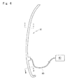
Fig. 1 is a perspective view of a lower side terminal part of a protector with a sensor according to an embodiment of the present invention at a time of die molding; -
Fig. 2 is a perspective view of an insert of the protector with the sensor according to the embodiment of the present invention; -
Fig. 3 (a) and Fig. 3 (b) are cross sections of another insert of the protector with the sensor according to the embodiment of the present invention; -
Fig. 4 is a side view of an automobile which opens or closes by a sliding door; -
Fig. 5 is a perspective view of an automobile with a sun roof; -
Fig. 6 is a side view of the protector with the sensor ofFig. 4 ; -
Fig. 7 is a I-I line enlarged cross section ofFig. 6 ; -
Fig. 8 is a II-II line enlarged cross section ofFig. 6 ; -
Fig. 9 (a), Fig. 9 (b) and Fig. 9 (c) are perspective views of processes before die molding a lower side terminal part of a protector with a sensor according to a prior art; -
Fig. 10 is a perspective view of a structural gist of the lower side terminal part of the protector with the sensor according to the prior art after die molding; and -
Fig. 11 is a perspective view of a structural gist of an upper side terminal part of the protector with the sensor according to the prior art after die molding. - Referring to
Fig. 1 ,Fig 2 ,Fig. 4 to Fig. 11 , a protector with a sensor according to an embodiment of the present invention will be described. - A
protector 10 with a sensor of the embodiment of the present invention, which extends toward a front side of an automobile body is installed on a front end surface of a slidingdoor 1 of an automobile shown inFig. 4 of which the slidingdoor 1 opens or closes an opening of the automobile body. A sensor (pressure sensitive sensor) 80 installed on theprotector 10 with the sensor outputs corresponding electric signal upon detecting an alien substance such as a part of human body (finger, hand or leg) between the slidingdoor 1 and a body side opening (may also be front door or side door). Both the present invention and the prior art comprise the structures ofFig. 6 to Fig. 8 . But aninsert 50 of the present invention is different from aninsert 25 of the prior art in structure and material. Also, the present invention is different from the prior art in the following aspects: core wires (electrode wires) 31, 32 are connected withleads 36 which are further connected with leads joined with acontrol unit 40 or an electrical component for detecting the alien substance based on change in electric signal in thecore wires wire connection parts 70 of thecore wires - The
protector 10 with the sensor comprises: aninstallation base member 11 operatively coupled on a flange (not shown) formed on a slidingdoor 1 directly; ahollow part 12 which is integrally molded with theinstallation base member 11 and which makes elastic contact with the alien substance when the alien substance including a finger is caught between a front end surface of the slidingdoor 1 and a body side opening which faces the front end surface while closing thedoor 1; and the sensor (pressure sensitive sensor) 80 which is incorporated in thehollow part 12 and which outputs a corresponding electric signal upon detecting the alien substance. The sensor (pressure sensitive sensor) 80 has two core wires (electrode wires) 31, 32 extending in an upper and lower direction (longitudinal direction) embedded in conductive rubber-likeelastic bodies space 33 therebetween, which are fixed in thehollow part 12. - As shown in
Fig. 1 , in a lower side terminal part of theprotector 10 with the sensor, theinsert 50 having a shape shown inFig. 2 fills up thespace 33 of thehollow part 12, which is open in the lower side terminal part. - The
insert 50 is made of a flexible and non-conductive material and comprises aninsertion part 51 on one end side and aprotrusion part 52 having a substantially heart-shaped cross section on another end side. In the present embodiment, length of theinsertion part 51 and theprotrusion part 52 in a longitudinal direction is substantially the same but the length is not specifically limited. - The
insertion part 51 has a cross sectional shape which is substantially the same as or a little larger than thespace 33 for being pressed in thespace 33 of thehollow part 12 and tightly filling up thespace 33, thereby preventing decline in sensor function caused by die molding material flowing in thespace 33 during die molding. In the present embodiment, theinsertion part 51 has a substantially ridge shaped cross section. Since a cross section of aspace 33 ofFig. 9 is a little different from the present embodiment, aninsertion part 51 having a cross sectional shape corresponding to thespace 33 ofFig. 9 is used. In other words, the cross sectional shape of theinsertion part 51 corresponds to the cross sectional shape of thespace 33 for tightly filling up thespace 33. - As shown in
Fig. 2 , theprotrusion part 52 has twochannels wire connection parts 70 and encloses the storedwire connection parts 70 by peripheral edges forming thechannels channel 55 is a concave having an opening covered with right and leftoverhangs channel 55 has a cross sectional shape of a keyhole. - The
channel 55 stores: thewire connection part 70 formed by piling a naked wire of a top end of thelead 36 joined with thecontrol unit 40 on thecore wire 31 drawn out from thehollow part 12 toward a lower side in a longitudinal direction, and connecting thelead 36 and thecore wire 31 by resistance welding or soft soldering; and a top end of acovered part 37 of thelead 36. Thechannel 58 stores: thewire connection part 70 formed by piling the naked wire of the top end of a lead 36 joined with thecontrol unit 40 on theother core wire 32 drawn out from thehollow part 12 toward the lower side in the longitudinal direction, and connecting thelead 36 and thecore wire 32 by the resistance welding or the soft soldering; and the top end of the coveredpart 37 of thelead 36. - An interval between the right and left
overhangs channel 55 is shorter than a diameter of the coveredpart 37 of thelead 36 so that thewire connection part 70 and the coveredpart 37 once stored in thechannel 55 do not easily come off from appropriate positions. Surroundingwalls channel 58 widen toward outer sides so that positioning of thewire connection part 70 and the coveredpart 37 in thechannel 58 is easy. - A cross sectional shape of the
channel 55, which is substantially the same as or a little smaller than the diameter of the coveredpart 37 enables to firmly keep thecovered part 37 in thechannel 55. - In the present embodiment, the materials of the
insert 50 and the die molding material are soft TPO materials for keeping compatibility of theinsert 50 and the die molding material well. - By die molding the lower end part of the
protector 10, theinsert 50, thewire connection part 70, the coveredpart 37 and a part of thewire harness 90 are embedded in a die molded part and are not exposed. - As both of the materials of the
insert 50, which fills up thespace 33 from an opening of thehollow part 12, and the die molding material are the same soft TPO materials, when a shape modelled on theinsert 50 is embedded in a part of the die for molding the terminal part of theprotector 10 with the sensor, theinsert 50 can be simultaneously molded while the terminal part is being molded. - The structure does not necessitate a die exclusively for the
insert 50 for manufacturing theinsert 50 in an extra process as in the prior art, thereby reducing costs of manufacturing components and production. Also, the structure which enables the simultaneous molding of the insert as well as the terminal part in the single die molding is excellent in operability. - The
insert 50 has thechannels wire connection parts 70 of thecore wires leads 36, and encloses thewire connection parts 70. The structure enables the die molding while keeping thewire connection parts 70 on appropriate positions without using adhesive as in the prior arts. - The structure easily prevents exposure of the
wire connection parts 70 from the die molded part or damages to the wires, caused by the injection molding pressure during the die molding, and does not degrade external appearance. - The structure without use of the adhesive does not necessitate an extra process and does not cause insufficient adherence.
- In addition, one of the
channels 55 is the concave having the opening covered with the right and leftoverhangs wire connection part 70 stored in thechannel 55 is kept more stably and does not easily expose from the die molded part. - Especially, when the materials of the
insert 50 and the die molding material are soft TPO materials, theinsert 50 can have further flexibility and can be easily taken off from the die after molding, thechannels wire connection parts 70 can be simply shaped on theinsert 50 and structure of the die can be simplified. The structure forms sense of unification between theinsert 50 and the die molding material and simplifies handling of theprotector 10 with the sensor. - In the present embodiment, the
insert 50 and the die molding material are made of soft TPO materials. But any materials having compatibility with each other, and preferably having homogeneity in such a manner as to mutually fuse during the die molding, are usable as theinsert 50 and the die molding material. - The
insert 50 and the die molding material may have homogeneity in such a manner as to mutually fuse. The structure further achieves the sense of unification between theinsert 50 and the die molding material and further simplifies handling of theprotector 10 with the sensor. In addition, since theinsert 50 adheres to the die molding material during the die molding without adhesive, entrance of water toward the internal electrical component or the wiring is prevented. It is to be noted that to "have homogeneity in such a manner as to mutually fuse" during the die molding means to assure that theinsert 50 and the die molding material are homogeneous in such a manner as to mutually fuse during the die molding: in case the die molding material is made of TPO, theinsert 50 may be TPE containing polypropylene, polyethylene, TPO or olefin resin. Examples of the TPE containing olefin resin include styrene thermoplastic elastomer (TPS). In case the die molding material is made of TPS, by adding olefin resin to the TPS, the above-mentioned examples of the material of theinsert 50 can have homogeneity to fuse with the die molding material in a similar manner as a case the die molding material is made of TPO. - Materials of the
insert 50 and the die molding material may have the same degree of rigidity. Said structure further achieves the sense of unification of theinsert 50 and the die molding material and further simplifies handling of theprotector 10 with the sensor. The rigidity (hardness) is preferably in a range of JISA 20 to 90, and more preferably,JISA 40 to 90. JIS is an abbreviation of Japanese Industrial Standards, wherein JISA is measured by a type A durometer. When the rigidity is less than JISA 40, the die molded part may insufficiently function (such as assembling property on the automobile body) and when the rigidity is less than JISA 20, the die molded part does not sufficiently function. In case theinsert 50 is wrapped with an extra resin material (adhesive, for example) for preventing the entrance of water toward the internal electrical component or wiring, the extra resin material which is as soft as or softer (lower rigidity) than the die molding material does not hamper the above-mentioned sense of unification. - In the present embodiment, as shown in
Fig. 2 , theprotrusion part 52 having a substantially heart-shaped cross section has thechannels wire connection parts 70 and the coveredparts 37. But the shape of theinsert 50 is not especially limited and theinsert 50 of any shape provided with surrounding walls for enclosing thewire connection parts 70 and the coveredparts 37 as well as the channels for storing thewire connection parts 70 and the coveredparts 37 is usable. - Examples of variation of the
insert 50 includeFig. 3 (a) in which theinsert 50 has twochannels 55 formed thereon, that is, thechannel 58 is changed into thechannel 55 which is the concave having the opening covered with the right and leftoverhangs - Examples of the variation of the
insert 50 also includeFig. 3 (b) in which theinsert 50 has twoconcaves 65 having substantially C-shaped cross sections of which openings are covered with right and leftlips wire connection parts 70 and the coveredparts 37 are pressed into theconcaves 65 respectively so that top ends of thelips wire connection parts 70 or the coveredparts 37, thereby holding down thewire connection parts 70 or the coveredparts 37 inside theconcaves 65. - The present embodiment specifies the method of molding the lower side terminal part of the
protector 10 with the sensor. But the present invention is also applicable to an upper side terminal part of theprotector 10 with the sensor ofFig. 11 , provided with aresistor 39 as an electrical component. More specifically, as the materials of the insert filling up thespace 33 of thehollow part 12 in the upper side terminal part of theprotector 10 with the sensor and the die molding material are homogeneous, when a shape modelled on the insert is embedded in a part of a material flow passage inside the die for molding the terminal part, the insert can be simultaneously molded while the terminal part is being molded. - The present embodiment specifies an example that the
protector 10 with the sensor is installed on the slidingdoor 1 side of the automobile, which slides frontward and rearward. But theprotector 10 with the sensor may be installed on the body side opening for detecting the alien substance between the sliding door and the body side opening. - Also, the
protector 10 with the sensor is applicable to a back door or a sun roof 2 (Fig. 5 ).
Claims (5)
- A protector with a sensor comprising: an installation base member operatively coupled on a peripheral edge of an opening or closing object for opening or closing an opening of an automobile body, the opening or closing object including a door or a sun roof of an automobile, or on a peripheral edge of said opening; and a hollow part integrally molded with the installation base member, the hollow part having two core wires and a space provided therein, the space being positioned between the two core wires, in which:when an alien substance caught between said opening or closing object and said opening presses and crushes said hollow part while closing said opening or closing object, a corresponding change in electric signal detects said alien substance; andin a terminal part, said core wires drawn out in a longitudinal direction are connected with leads, said leads being joined with a control unit or an electrical component, and one end side of an insert made of a non-conductive material is inserted in and fills up said space, and said terminal part is die molded, wherein:materials of said insert and said die molding material have compatibility with each other.
- The protector with the sensor as claimed in Claim 1, wherein: both of the materials of said insert and said die molding material are soft TPE materials.
- The protector with the sensor as claimed in Claim 1 or 2, wherein: said insert is made of a flexible material, has channels formed thereon for storing wire connection parts of said core wires and the leads and encloses the wire connection parts.
- The protector with the sensor as claimed in Claim 3, wherein: said channels are concaves having openings covered with right and left overhangs overhanging from both sides toward inner sides.
- A method of molding an end part of a protector with a sensor comprising: an installation base member operatively coupled on a peripheral edge of an opening or closing object for opening or closing an opening of an automobile body, the opening or closing object including a door or a sun roof of an automobile, or on a peripheral edge of said opening; and a hollow part integrally molded with the installation base member, the hollow part having two core wires and a space provided therein, the space being positioned between the two core wires, in which:when an alien substance caught between said opening or closing object and said opening presses and crushes said hollow part while closing said opening or closing object, a corresponding change in electric signal detects said alien substance; andin a terminal part, said core wires drawn out in a longitudinal direction are connected with leads, said leads being joined with a control unit or an electrical component, and one end side of an insert made of a non-conductive material is inserted in and fills up said space, and said terminal part is die molded, wherein:materials of said insert and said die molding material are the same and said insert is simultaneously die molded while the end part of said protector is being die molded.
Applications Claiming Priority (1)
| Application Number | Priority Date | Filing Date | Title |
|---|---|---|---|
| JP2013106634A JP6219597B2 (en) | 2013-05-20 | 2013-05-20 | Protector with sensor |
Publications (2)
| Publication Number | Publication Date |
|---|---|
| EP2805841A1 true EP2805841A1 (en) | 2014-11-26 |
| EP2805841B1 EP2805841B1 (en) | 2016-09-21 |
Family
ID=50842028
Family Applications (1)
| Application Number | Title | Priority Date | Filing Date |
|---|---|---|---|
| EP14167619.7A Active EP2805841B1 (en) | 2013-05-20 | 2014-05-09 | Protector with sensor and method of molding end part of the same |
Country Status (4)
| Country | Link |
|---|---|
| US (1) | US9114691B2 (en) |
| EP (1) | EP2805841B1 (en) |
| JP (1) | JP6219597B2 (en) |
| CN (1) | CN104175844B (en) |
Families Citing this family (19)
| Publication number | Priority date | Publication date | Assignee | Title |
|---|---|---|---|---|
| US11634937B2 (en) * | 2009-08-21 | 2023-04-25 | Uusi, Llc | Vehicle assembly having a capacitive sensor |
| JP6258735B2 (en) * | 2014-03-18 | 2018-01-10 | 西川ゴム工業株式会社 | Protector with sensor and end molding method for protector with sensor |
| JP6258734B2 (en) * | 2014-03-18 | 2018-01-10 | 西川ゴム工業株式会社 | Protector with sensor and end molding method for protector with sensor |
| JP6427398B2 (en) * | 2014-11-21 | 2018-11-21 | 西川ゴム工業株式会社 | Protector with sensor |
| JP6418913B2 (en) * | 2014-11-21 | 2018-11-07 | 西川ゴム工業株式会社 | Protector with sensor and end molding method for protector with sensor |
| JP6424074B2 (en) * | 2014-11-21 | 2018-11-14 | 西川ゴム工業株式会社 | Protector with sensor |
| JP6520340B2 (en) * | 2015-04-16 | 2019-05-29 | アイシン精機株式会社 | Pinch detection device |
| JP6766718B2 (en) * | 2017-03-23 | 2020-10-14 | 株式会社デンソー | Sensor mounting bracket and lead wire wiring structure |
| JP6890762B2 (en) * | 2017-05-30 | 2021-06-18 | 株式会社アイシン | Touch sensor unit |
| CN111094686B (en) * | 2017-09-19 | 2022-01-25 | 克诺尔有限公司 | Anti-pinch device for a vehicle door, door system for a vehicle and method for producing an anti-pinch device for a vehicle door |
| JP6516052B1 (en) * | 2018-06-25 | 2019-05-22 | 日立金属株式会社 | Pinch detection sensor |
| CN109057605A (en) * | 2018-08-06 | 2018-12-21 | 上海荣南科技有限公司 | A kind of high sensitivity, car anti-clamping item easy to install, at low cost |
| CN110056281A (en) * | 2019-03-14 | 2019-07-26 | 佛山市百斯特电器科技有限公司 | A kind of finger dish-washing machine and its control method |
| JP7221753B2 (en) * | 2019-03-21 | 2023-02-14 | 西川ゴム工業株式会社 | Seal structure of sliding door with touch sensor |
| KR20210019623A (en) * | 2019-08-12 | 2021-02-23 | 현대자동차주식회사 | Body weather strip for vehicle |
| CN111301531B (en) * | 2020-03-30 | 2021-02-12 | 杭州富阳新远新能源有限公司 | Hand B post is prevented pressing from both sides by car |
| JP7355702B2 (en) * | 2020-04-21 | 2023-10-03 | 西川ゴム工業株式会社 | protector with sensor |
| US20230003071A1 (en) * | 2021-07-01 | 2023-01-05 | Nishikawa Rubber Co., Ltd. | Protector with sensor and method of manufacturing the same |
| US11850922B2 (en) * | 2022-04-05 | 2023-12-26 | Honda Motor Co., Ltd. | Door seal and sensor assembly for motor vehicle |
Citations (7)
| Publication number | Priority date | Publication date | Assignee | Title |
|---|---|---|---|---|
| EP1043471A1 (en) * | 1997-12-24 | 2000-10-11 | Asmo Co. Ltd. | Automatic opening and closing device |
| JP2001297842A (en) | 2000-04-12 | 2001-10-26 | Yazaki Corp | Connector and pinched sensor having connector |
| JP2005114395A (en) | 2003-10-03 | 2005-04-28 | Matsushita Electric Ind Co Ltd | Pressure-sensitive sensor and manufacturing method therefor |
| US20080000166A1 (en) * | 2001-04-18 | 2008-01-03 | Schlegel Corporation | Illuminating weatherseal for vehicular sunroof |
| JP2010015696A (en) | 2008-07-01 | 2010-01-21 | Shiroki Corp | Sensor |
| JP2010137808A (en) * | 2008-12-15 | 2010-06-24 | Shiroki Corp | Sensor |
| US20120222296A1 (en) * | 2011-03-03 | 2012-09-06 | Asmo Co., Ltd. | Manufacturing method of foreign object detection apparatus |
Family Cites Families (30)
| Publication number | Priority date | Publication date | Assignee | Title |
|---|---|---|---|---|
| FR2643171A1 (en) * | 1989-02-13 | 1990-08-17 | Jaeger | OBSTACLE DETECTOR SYSTEM INCLUDING AN IMPROVED CONNECTION ASSEMBLY |
| FR2643172A1 (en) * | 1989-02-13 | 1990-08-17 | Jaeger | LOW SIZE OBSTACLE DETECTOR |
| US5087799A (en) * | 1990-12-27 | 1992-02-11 | Techstrip Inc. | Power Door sensing strip |
| US5079417A (en) * | 1991-02-22 | 1992-01-07 | Link Controls, Inc. | Failsafe sensing edge for automatic doors and gates |
| WO1994008119A1 (en) * | 1992-09-25 | 1994-04-14 | Rockwell International Corporation | Safety edge switch system |
| US5438798A (en) * | 1993-07-19 | 1995-08-08 | Action Industries, Inc. | Safety edge assembly for a movable closure |
| DE9321338U1 (en) * | 1993-08-09 | 1997-06-12 | Metzeler Automotive Profiles | Pinch protection for power operated locking devices |
| US5418342A (en) * | 1993-09-17 | 1995-05-23 | Miller Edge, Inc. | Door edge sensing switch |
| US5728984A (en) * | 1996-11-20 | 1998-03-17 | Miller Edge, Inc. | Sensing safety edge systems |
| JP3825159B2 (en) * | 1997-12-24 | 2006-09-20 | アスモ株式会社 | Automatic switchgear |
| JPH11222036A (en) * | 1998-02-03 | 1999-08-17 | Toyota Auto Body Co Ltd | Touch sensor for electric motor-driven slide door |
| EP0935268A3 (en) * | 1998-02-09 | 2000-09-06 | Shinmei Rubber Ind. Co., Ltd. | Omnidirectional response cable switch |
| US5962825A (en) * | 1998-06-15 | 1999-10-05 | Miller Edge, Inc. | Universal sensing edge |
| JP2000137808A (en) * | 1998-11-02 | 2000-05-16 | Ricoh Co Ltd | Method for recognizing three-dimensional object |
| DE19913106C1 (en) * | 1999-03-23 | 2000-05-04 | Metzeler Automotive Profiles | All-round anti-nipping protection for power-operated sliding roof or window of vehicle, comprises rubbery hollow elastic profile containing electrodes tripping-off electric motor controller, when pressed together into contact |
| US6483054B2 (en) * | 2000-02-29 | 2002-11-19 | Yazaki Corporation | Pressure-sensitive sensor, connector and combining structure thereof |
| US20030000815A1 (en) * | 2001-06-07 | 2003-01-02 | Burgess Lester E. | Elongate pressure actuated switch |
| US6689970B2 (en) * | 2001-10-04 | 2004-02-10 | Lester E. Burgess | Pressure actuated switching device and method and system for making same |
| JP3844684B2 (en) * | 2001-12-11 | 2006-11-15 | アスモ株式会社 | Pressure sensor and terminal processing method of pressure sensor |
| US6571512B1 (en) * | 2002-04-24 | 2003-06-03 | Miller Edge, Inc. | Universal sensing edge with non-melt end closure |
| JP3831325B2 (en) * | 2002-10-01 | 2006-10-11 | アスモ株式会社 | Switchgear |
| JP2005096736A (en) * | 2003-08-29 | 2005-04-14 | Toyoda Gosei Co Ltd | Glass run |
| WO2006101109A1 (en) * | 2005-03-22 | 2006-09-28 | Asmo Co., Ltd. | Opening/closing device |
| US7504943B2 (en) * | 2005-07-27 | 2009-03-17 | Aisin Seiki Kabushiki Kaisha | Object detecting apparatus |
| JP4108700B2 (en) * | 2005-09-08 | 2008-06-25 | 東海興業株式会社 | Manufacturing method and manufacturing apparatus of composite molded product |
| JP4504904B2 (en) * | 2005-10-31 | 2010-07-14 | アスモ株式会社 | Code switch and detection device using the same |
| JP4692303B2 (en) * | 2006-01-27 | 2011-06-01 | 豊田合成株式会社 | Manufacturing method of glass run |
| CN201024825Y (en) * | 2007-02-13 | 2008-02-20 | 刘旭辉 | Clamping-proof electric glass window lifter drive device and its driving system |
| JP2011158336A (en) * | 2010-01-29 | 2011-08-18 | Asmo Co Ltd | Method for manufacturing pressure sensitive sensor, and pressure sensitive sensor |
| EP2439368A3 (en) * | 2010-10-05 | 2014-07-23 | Miller Edge, Inc. | Resistor storage cavity in plug of sensing edge |
-
2013
- 2013-05-20 JP JP2013106634A patent/JP6219597B2/en active Active
-
2014
- 2014-05-06 CN CN201410188200.4A patent/CN104175844B/en active Active
- 2014-05-09 EP EP14167619.7A patent/EP2805841B1/en active Active
- 2014-05-14 US US14/277,266 patent/US9114691B2/en active Active
Patent Citations (7)
| Publication number | Priority date | Publication date | Assignee | Title |
|---|---|---|---|---|
| EP1043471A1 (en) * | 1997-12-24 | 2000-10-11 | Asmo Co. Ltd. | Automatic opening and closing device |
| JP2001297842A (en) | 2000-04-12 | 2001-10-26 | Yazaki Corp | Connector and pinched sensor having connector |
| US20080000166A1 (en) * | 2001-04-18 | 2008-01-03 | Schlegel Corporation | Illuminating weatherseal for vehicular sunroof |
| JP2005114395A (en) | 2003-10-03 | 2005-04-28 | Matsushita Electric Ind Co Ltd | Pressure-sensitive sensor and manufacturing method therefor |
| JP2010015696A (en) | 2008-07-01 | 2010-01-21 | Shiroki Corp | Sensor |
| JP2010137808A (en) * | 2008-12-15 | 2010-06-24 | Shiroki Corp | Sensor |
| US20120222296A1 (en) * | 2011-03-03 | 2012-09-06 | Asmo Co., Ltd. | Manufacturing method of foreign object detection apparatus |
Also Published As
| Publication number | Publication date |
|---|---|
| JP6219597B2 (en) | 2017-10-25 |
| JP2014226984A (en) | 2014-12-08 |
| CN104175844B (en) | 2018-09-28 |
| US9114691B2 (en) | 2015-08-25 |
| EP2805841B1 (en) | 2016-09-21 |
| US20140339842A1 (en) | 2014-11-20 |
| CN104175844A (en) | 2014-12-03 |
Similar Documents
| Publication | Publication Date | Title |
|---|---|---|
| EP2805841B1 (en) | Protector with sensor and method of molding end part of the same | |
| EP2922075B1 (en) | Protector with sensor | |
| EP2921330B1 (en) | Protector with sensor and method of molding end part of the same | |
| EP2835486B1 (en) | Protector with sensor and method of molding end part of the same | |
| EP2922076B1 (en) | Protector with sensor and method of molding end part of the same | |
| JP7303716B2 (en) | protector with sensor | |
| JP6231317B2 (en) | Protector with sensor | |
| JP2021172165A (en) | Protector with sensor | |
| JP6231318B2 (en) | Protector with sensor | |
| JP6418913B2 (en) | Protector with sensor and end molding method for protector with sensor | |
| JP6118636B2 (en) | Protector with sensor | |
| JP6110728B2 (en) | Protector with sensor | |
| US20230003071A1 (en) | Protector with sensor and method of manufacturing the same | |
| JP2023008811A (en) | Protector with sensor and manufacturing method thereof |
Legal Events
| Date | Code | Title | Description |
|---|---|---|---|
| PUAI | Public reference made under article 153(3) epc to a published international application that has entered the european phase |
Free format text: ORIGINAL CODE: 0009012 |
|
| 17P | Request for examination filed |
Effective date: 20140509 |
|
| AK | Designated contracting states |
Kind code of ref document: A1 Designated state(s): AL AT BE BG CH CY CZ DE DK EE ES FI FR GB GR HR HU IE IS IT LI LT LU LV MC MK MT NL NO PL PT RO RS SE SI SK SM TR |
|
| AX | Request for extension of the european patent |
Extension state: BA ME |
|
| R17P | Request for examination filed (corrected) |
Effective date: 20150417 |
|
| RBV | Designated contracting states (corrected) |
Designated state(s): AL AT BE BG CH CY CZ DE DK EE ES FI FR GB GR HR HU IE IS IT LI LT LU LV MC MK MT NL NO PL PT RO RS SE SI SK SM TR |
|
| 17Q | First examination report despatched |
Effective date: 20151123 |
|
| REG | Reference to a national code |
Ref country code: DE Ref legal event code: R079 Ref document number: 602014003748 Country of ref document: DE Free format text: PREVIOUS MAIN CLASS: B60J0010000000 Ipc: B29C0045160000 |
|
| GRAP | Despatch of communication of intention to grant a patent |
Free format text: ORIGINAL CODE: EPIDOSNIGR1 |
|
| RIC1 | Information provided on ipc code assigned before grant |
Ipc: E05F 15/44 20150101ALI20160620BHEP Ipc: B60J 5/04 20060101ALI20160620BHEP Ipc: B60J 10/24 20160101ALI20160620BHEP Ipc: B60J 10/82 20160101ALI20160620BHEP Ipc: B60J 10/32 20160101ALI20160620BHEP Ipc: B60J 10/86 20160101ALI20160620BHEP Ipc: B60J 10/273 20160101ALI20160620BHEP Ipc: B29C 45/16 20060101AFI20160620BHEP |
|
| INTG | Intention to grant announced |
Effective date: 20160712 |
|
| GRAS | Grant fee paid |
Free format text: ORIGINAL CODE: EPIDOSNIGR3 |
|
| GRAA | (expected) grant |
Free format text: ORIGINAL CODE: 0009210 |
|
| AK | Designated contracting states |
Kind code of ref document: B1 Designated state(s): AL AT BE BG CH CY CZ DE DK EE ES FI FR GB GR HR HU IE IS IT LI LT LU LV MC MK MT NL NO PL PT RO RS SE SI SK SM TR |
|
| REG | Reference to a national code |
Ref country code: GB Ref legal event code: FG4D |
|
| REG | Reference to a national code |
Ref country code: CH Ref legal event code: EP |
|
| REG | Reference to a national code |
Ref country code: AT Ref legal event code: REF Ref document number: 830678 Country of ref document: AT Kind code of ref document: T Effective date: 20161015 |
|
| REG | Reference to a national code |
Ref country code: IE Ref legal event code: FG4D |
|
| REG | Reference to a national code |
Ref country code: DE Ref legal event code: R096 Ref document number: 602014003748 Country of ref document: DE |
|
| REG | Reference to a national code |
Ref country code: LT Ref legal event code: MG4D Ref country code: NL Ref legal event code: MP Effective date: 20160921 |
|
| PG25 | Lapsed in a contracting state [announced via postgrant information from national office to epo] |
Ref country code: FI Free format text: LAPSE BECAUSE OF FAILURE TO SUBMIT A TRANSLATION OF THE DESCRIPTION OR TO PAY THE FEE WITHIN THE PRESCRIBED TIME-LIMIT Effective date: 20160921 Ref country code: RS Free format text: LAPSE BECAUSE OF FAILURE TO SUBMIT A TRANSLATION OF THE DESCRIPTION OR TO PAY THE FEE WITHIN THE PRESCRIBED TIME-LIMIT Effective date: 20160921 Ref country code: LT Free format text: LAPSE BECAUSE OF FAILURE TO SUBMIT A TRANSLATION OF THE DESCRIPTION OR TO PAY THE FEE WITHIN THE PRESCRIBED TIME-LIMIT Effective date: 20160921 Ref country code: NO Free format text: LAPSE BECAUSE OF FAILURE TO SUBMIT A TRANSLATION OF THE DESCRIPTION OR TO PAY THE FEE WITHIN THE PRESCRIBED TIME-LIMIT Effective date: 20161221 |
|
| REG | Reference to a national code |
Ref country code: AT Ref legal event code: MK05 Ref document number: 830678 Country of ref document: AT Kind code of ref document: T Effective date: 20160921 |
|
| PG25 | Lapsed in a contracting state [announced via postgrant information from national office to epo] |
Ref country code: SE Free format text: LAPSE BECAUSE OF FAILURE TO SUBMIT A TRANSLATION OF THE DESCRIPTION OR TO PAY THE FEE WITHIN THE PRESCRIBED TIME-LIMIT Effective date: 20160921 Ref country code: LV Free format text: LAPSE BECAUSE OF FAILURE TO SUBMIT A TRANSLATION OF THE DESCRIPTION OR TO PAY THE FEE WITHIN THE PRESCRIBED TIME-LIMIT Effective date: 20160921 Ref country code: GR Free format text: LAPSE BECAUSE OF FAILURE TO SUBMIT A TRANSLATION OF THE DESCRIPTION OR TO PAY THE FEE WITHIN THE PRESCRIBED TIME-LIMIT Effective date: 20161222 Ref country code: NL Free format text: LAPSE BECAUSE OF FAILURE TO SUBMIT A TRANSLATION OF THE DESCRIPTION OR TO PAY THE FEE WITHIN THE PRESCRIBED TIME-LIMIT Effective date: 20160921 |
|
| REG | Reference to a national code |
Ref country code: FR Ref legal event code: PLFP Year of fee payment: 4 |
|
| PG25 | Lapsed in a contracting state [announced via postgrant information from national office to epo] |
Ref country code: EE Free format text: LAPSE BECAUSE OF FAILURE TO SUBMIT A TRANSLATION OF THE DESCRIPTION OR TO PAY THE FEE WITHIN THE PRESCRIBED TIME-LIMIT Effective date: 20160921 Ref country code: RO Free format text: LAPSE BECAUSE OF FAILURE TO SUBMIT A TRANSLATION OF THE DESCRIPTION OR TO PAY THE FEE WITHIN THE PRESCRIBED TIME-LIMIT Effective date: 20160921 |
|
| PG25 | Lapsed in a contracting state [announced via postgrant information from national office to epo] |
Ref country code: PT Free format text: LAPSE BECAUSE OF FAILURE TO SUBMIT A TRANSLATION OF THE DESCRIPTION OR TO PAY THE FEE WITHIN THE PRESCRIBED TIME-LIMIT Effective date: 20170123 Ref country code: PL Free format text: LAPSE BECAUSE OF FAILURE TO SUBMIT A TRANSLATION OF THE DESCRIPTION OR TO PAY THE FEE WITHIN THE PRESCRIBED TIME-LIMIT Effective date: 20160921 Ref country code: AT Free format text: LAPSE BECAUSE OF FAILURE TO SUBMIT A TRANSLATION OF THE DESCRIPTION OR TO PAY THE FEE WITHIN THE PRESCRIBED TIME-LIMIT Effective date: 20160921 Ref country code: ES Free format text: LAPSE BECAUSE OF FAILURE TO SUBMIT A TRANSLATION OF THE DESCRIPTION OR TO PAY THE FEE WITHIN THE PRESCRIBED TIME-LIMIT Effective date: 20160921 Ref country code: SK Free format text: LAPSE BECAUSE OF FAILURE TO SUBMIT A TRANSLATION OF THE DESCRIPTION OR TO PAY THE FEE WITHIN THE PRESCRIBED TIME-LIMIT Effective date: 20160921 Ref country code: BE Free format text: LAPSE BECAUSE OF FAILURE TO SUBMIT A TRANSLATION OF THE DESCRIPTION OR TO PAY THE FEE WITHIN THE PRESCRIBED TIME-LIMIT Effective date: 20160921 Ref country code: IS Free format text: LAPSE BECAUSE OF FAILURE TO SUBMIT A TRANSLATION OF THE DESCRIPTION OR TO PAY THE FEE WITHIN THE PRESCRIBED TIME-LIMIT Effective date: 20170121 Ref country code: CZ Free format text: LAPSE BECAUSE OF FAILURE TO SUBMIT A TRANSLATION OF THE DESCRIPTION OR TO PAY THE FEE WITHIN THE PRESCRIBED TIME-LIMIT Effective date: 20160921 Ref country code: SM Free format text: LAPSE BECAUSE OF FAILURE TO SUBMIT A TRANSLATION OF THE DESCRIPTION OR TO PAY THE FEE WITHIN THE PRESCRIBED TIME-LIMIT Effective date: 20160921 Ref country code: BG Free format text: LAPSE BECAUSE OF FAILURE TO SUBMIT A TRANSLATION OF THE DESCRIPTION OR TO PAY THE FEE WITHIN THE PRESCRIBED TIME-LIMIT Effective date: 20161221 |
|
| REG | Reference to a national code |
Ref country code: DE Ref legal event code: R097 Ref document number: 602014003748 Country of ref document: DE |
|
| PG25 | Lapsed in a contracting state [announced via postgrant information from national office to epo] |
Ref country code: IT Free format text: LAPSE BECAUSE OF FAILURE TO SUBMIT A TRANSLATION OF THE DESCRIPTION OR TO PAY THE FEE WITHIN THE PRESCRIBED TIME-LIMIT Effective date: 20160921 |
|
| PLBE | No opposition filed within time limit |
Free format text: ORIGINAL CODE: 0009261 |
|
| STAA | Information on the status of an ep patent application or granted ep patent |
Free format text: STATUS: NO OPPOSITION FILED WITHIN TIME LIMIT |
|
| PG25 | Lapsed in a contracting state [announced via postgrant information from national office to epo] |
Ref country code: DK Free format text: LAPSE BECAUSE OF FAILURE TO SUBMIT A TRANSLATION OF THE DESCRIPTION OR TO PAY THE FEE WITHIN THE PRESCRIBED TIME-LIMIT Effective date: 20160921 |
|
| 26N | No opposition filed |
Effective date: 20170622 |
|
| PG25 | Lapsed in a contracting state [announced via postgrant information from national office to epo] |
Ref country code: LU Free format text: LAPSE BECAUSE OF NON-PAYMENT OF DUE FEES Effective date: 20170531 |
|
| PG25 | Lapsed in a contracting state [announced via postgrant information from national office to epo] |
Ref country code: SI Free format text: LAPSE BECAUSE OF FAILURE TO SUBMIT A TRANSLATION OF THE DESCRIPTION OR TO PAY THE FEE WITHIN THE PRESCRIBED TIME-LIMIT Effective date: 20160921 |
|
| REG | Reference to a national code |
Ref country code: CH Ref legal event code: PL |
|
| PG25 | Lapsed in a contracting state [announced via postgrant information from national office to epo] |
Ref country code: MC Free format text: LAPSE BECAUSE OF FAILURE TO SUBMIT A TRANSLATION OF THE DESCRIPTION OR TO PAY THE FEE WITHIN THE PRESCRIBED TIME-LIMIT Effective date: 20160921 |
|
| REG | Reference to a national code |
Ref country code: IE Ref legal event code: MM4A |
|
| PG25 | Lapsed in a contracting state [announced via postgrant information from national office to epo] |
Ref country code: CH Free format text: LAPSE BECAUSE OF NON-PAYMENT OF DUE FEES Effective date: 20170531 Ref country code: LI Free format text: LAPSE BECAUSE OF NON-PAYMENT OF DUE FEES Effective date: 20170531 |
|
| PG25 | Lapsed in a contracting state [announced via postgrant information from national office to epo] |
Ref country code: LU Free format text: LAPSE BECAUSE OF NON-PAYMENT OF DUE FEES Effective date: 20170509 |
|
| REG | Reference to a national code |
Ref country code: FR Ref legal event code: PLFP Year of fee payment: 5 |
|
| PG25 | Lapsed in a contracting state [announced via postgrant information from national office to epo] |
Ref country code: IE Free format text: LAPSE BECAUSE OF NON-PAYMENT OF DUE FEES Effective date: 20170509 |
|
| PG25 | Lapsed in a contracting state [announced via postgrant information from national office to epo] |
Ref country code: MT Free format text: LAPSE BECAUSE OF NON-PAYMENT OF DUE FEES Effective date: 20170509 |
|
| PG25 | Lapsed in a contracting state [announced via postgrant information from national office to epo] |
Ref country code: AL Free format text: LAPSE BECAUSE OF FAILURE TO SUBMIT A TRANSLATION OF THE DESCRIPTION OR TO PAY THE FEE WITHIN THE PRESCRIBED TIME-LIMIT Effective date: 20160921 |
|
| PG25 | Lapsed in a contracting state [announced via postgrant information from national office to epo] |
Ref country code: HU Free format text: LAPSE BECAUSE OF FAILURE TO SUBMIT A TRANSLATION OF THE DESCRIPTION OR TO PAY THE FEE WITHIN THE PRESCRIBED TIME-LIMIT; INVALID AB INITIO Effective date: 20140509 |
|
| PG25 | Lapsed in a contracting state [announced via postgrant information from national office to epo] |
Ref country code: CY Free format text: LAPSE BECAUSE OF FAILURE TO SUBMIT A TRANSLATION OF THE DESCRIPTION OR TO PAY THE FEE WITHIN THE PRESCRIBED TIME-LIMIT Effective date: 20160921 |
|
| PG25 | Lapsed in a contracting state [announced via postgrant information from national office to epo] |
Ref country code: MK Free format text: LAPSE BECAUSE OF FAILURE TO SUBMIT A TRANSLATION OF THE DESCRIPTION OR TO PAY THE FEE WITHIN THE PRESCRIBED TIME-LIMIT Effective date: 20160921 |
|
| PG25 | Lapsed in a contracting state [announced via postgrant information from national office to epo] |
Ref country code: TR Free format text: LAPSE BECAUSE OF FAILURE TO SUBMIT A TRANSLATION OF THE DESCRIPTION OR TO PAY THE FEE WITHIN THE PRESCRIBED TIME-LIMIT Effective date: 20160921 |
|
| PG25 | Lapsed in a contracting state [announced via postgrant information from national office to epo] |
Ref country code: HR Free format text: LAPSE BECAUSE OF FAILURE TO SUBMIT A TRANSLATION OF THE DESCRIPTION OR TO PAY THE FEE WITHIN THE PRESCRIBED TIME-LIMIT Effective date: 20160921 |
|
| REG | Reference to a national code |
Ref country code: FR Ref legal event code: PLFP Year of fee payment: 10 |
|
| PGFP | Annual fee paid to national office [announced via postgrant information from national office to epo] |
Ref country code: GB Payment date: 20230330 Year of fee payment: 10 |
|
| PGFP | Annual fee paid to national office [announced via postgrant information from national office to epo] |
Ref country code: FR Payment date: 20230411 Year of fee payment: 10 Ref country code: DE Payment date: 20230331 Year of fee payment: 10 |