EP2805801A1 - Method and installations for processing a veneer and corresponding veneer - Google Patents
Method and installations for processing a veneer and corresponding veneer Download PDFInfo
- Publication number
- EP2805801A1 EP2805801A1 EP20130305683 EP13305683A EP2805801A1 EP 2805801 A1 EP2805801 A1 EP 2805801A1 EP 20130305683 EP20130305683 EP 20130305683 EP 13305683 A EP13305683 A EP 13305683A EP 2805801 A1 EP2805801 A1 EP 2805801A1
- Authority
- EP
- European Patent Office
- Prior art keywords
- veneer
- processing
- compression
- lignocellulosic
- opposed faces
- Prior art date
- Legal status (The legal status is an assumption and is not a legal conclusion. Google has not performed a legal analysis and makes no representation as to the accuracy of the status listed.)
- Granted
Links
Images


Classifications
-
- B—PERFORMING OPERATIONS; TRANSPORTING
- B27—WORKING OR PRESERVING WOOD OR SIMILAR MATERIAL; NAILING OR STAPLING MACHINES IN GENERAL
- B27N—MANUFACTURE BY DRY PROCESSES OF ARTICLES, WITH OR WITHOUT ORGANIC BINDING AGENTS, MADE FROM PARTICLES OR FIBRES CONSISTING OF WOOD OR OTHER LIGNOCELLULOSIC OR LIKE ORGANIC MATERIAL
- B27N3/00—Manufacture of substantially flat articles, e.g. boards, from particles or fibres
- B27N3/08—Moulding or pressing
-
- B—PERFORMING OPERATIONS; TRANSPORTING
- B27—WORKING OR PRESERVING WOOD OR SIMILAR MATERIAL; NAILING OR STAPLING MACHINES IN GENERAL
- B27D—WORKING VENEER OR PLYWOOD
- B27D1/00—Joining wood veneer with any material; Forming articles thereby; Preparatory processing of surfaces to be joined, e.g. scoring
- B27D1/005—Tenderising, e.g. by incising, crushing
-
- B—PERFORMING OPERATIONS; TRANSPORTING
- B27—WORKING OR PRESERVING WOOD OR SIMILAR MATERIAL; NAILING OR STAPLING MACHINES IN GENERAL
- B27M—WORKING OF WOOD NOT PROVIDED FOR IN SUBCLASSES B27B - B27L; MANUFACTURE OF SPECIFIC WOODEN ARTICLES
- B27M1/00—Working of wood not provided for in subclasses B27B - B27L, e.g. by stretching
- B27M1/02—Working of wood not provided for in subclasses B27B - B27L, e.g. by stretching by compressing
-
- B—PERFORMING OPERATIONS; TRANSPORTING
- B27—WORKING OR PRESERVING WOOD OR SIMILAR MATERIAL; NAILING OR STAPLING MACHINES IN GENERAL
- B27N—MANUFACTURE BY DRY PROCESSES OF ARTICLES, WITH OR WITHOUT ORGANIC BINDING AGENTS, MADE FROM PARTICLES OR FIBRES CONSISTING OF WOOD OR OTHER LIGNOCELLULOSIC OR LIKE ORGANIC MATERIAL
- B27N3/00—Manufacture of substantially flat articles, e.g. boards, from particles or fibres
- B27N3/08—Moulding or pressing
- B27N3/18—Auxiliary operations, e.g. preheating, humidifying, cutting-off
-
- B—PERFORMING OPERATIONS; TRANSPORTING
- B32—LAYERED PRODUCTS
- B32B—LAYERED PRODUCTS, i.e. PRODUCTS BUILT-UP OF STRATA OF FLAT OR NON-FLAT, e.g. CELLULAR OR HONEYCOMB, FORM
- B32B21/00—Layered products comprising a layer of wood, e.g. wood board, veneer, wood particle board
- B32B21/10—Next to a fibrous or filamentary layer
-
- B—PERFORMING OPERATIONS; TRANSPORTING
- B32—LAYERED PRODUCTS
- B32B—LAYERED PRODUCTS, i.e. PRODUCTS BUILT-UP OF STRATA OF FLAT OR NON-FLAT, e.g. CELLULAR OR HONEYCOMB, FORM
- B32B21/00—Layered products comprising a layer of wood, e.g. wood board, veneer, wood particle board
- B32B21/14—Layered products comprising a layer of wood, e.g. wood board, veneer, wood particle board comprising wood board or veneer
-
- B—PERFORMING OPERATIONS; TRANSPORTING
- B32—LAYERED PRODUCTS
- B32B—LAYERED PRODUCTS, i.e. PRODUCTS BUILT-UP OF STRATA OF FLAT OR NON-FLAT, e.g. CELLULAR OR HONEYCOMB, FORM
- B32B5/00—Layered products characterised by the non- homogeneity or physical structure, i.e. comprising a fibrous, filamentary, particulate or foam layer; Layered products characterised by having a layer differing constitutionally or physically in different parts
- B32B5/02—Layered products characterised by the non- homogeneity or physical structure, i.e. comprising a fibrous, filamentary, particulate or foam layer; Layered products characterised by having a layer differing constitutionally or physically in different parts characterised by structural features of a fibrous or filamentary layer
- B32B5/022—Non-woven fabric
-
- B—PERFORMING OPERATIONS; TRANSPORTING
- B32—LAYERED PRODUCTS
- B32B—LAYERED PRODUCTS, i.e. PRODUCTS BUILT-UP OF STRATA OF FLAT OR NON-FLAT, e.g. CELLULAR OR HONEYCOMB, FORM
- B32B5/00—Layered products characterised by the non- homogeneity or physical structure, i.e. comprising a fibrous, filamentary, particulate or foam layer; Layered products characterised by having a layer differing constitutionally or physically in different parts
- B32B5/02—Layered products characterised by the non- homogeneity or physical structure, i.e. comprising a fibrous, filamentary, particulate or foam layer; Layered products characterised by having a layer differing constitutionally or physically in different parts characterised by structural features of a fibrous or filamentary layer
- B32B5/024—Woven fabric
-
- Y—GENERAL TAGGING OF NEW TECHNOLOGICAL DEVELOPMENTS; GENERAL TAGGING OF CROSS-SECTIONAL TECHNOLOGIES SPANNING OVER SEVERAL SECTIONS OF THE IPC; TECHNICAL SUBJECTS COVERED BY FORMER USPC CROSS-REFERENCE ART COLLECTIONS [XRACs] AND DIGESTS
- Y10—TECHNICAL SUBJECTS COVERED BY FORMER USPC
- Y10T—TECHNICAL SUBJECTS COVERED BY FORMER US CLASSIFICATION
- Y10T156/00—Adhesive bonding and miscellaneous chemical manufacture
- Y10T156/10—Methods of surface bonding and/or assembly therefor
-
- Y—GENERAL TAGGING OF NEW TECHNOLOGICAL DEVELOPMENTS; GENERAL TAGGING OF CROSS-SECTIONAL TECHNOLOGIES SPANNING OVER SEVERAL SECTIONS OF THE IPC; TECHNICAL SUBJECTS COVERED BY FORMER USPC CROSS-REFERENCE ART COLLECTIONS [XRACs] AND DIGESTS
- Y10—TECHNICAL SUBJECTS COVERED BY FORMER USPC
- Y10T—TECHNICAL SUBJECTS COVERED BY FORMER US CLASSIFICATION
- Y10T156/00—Adhesive bonding and miscellaneous chemical manufacture
- Y10T156/10—Methods of surface bonding and/or assembly therefor
- Y10T156/1002—Methods of surface bonding and/or assembly therefor with permanent bending or reshaping or surface deformation of self sustaining lamina
- Y10T156/1043—Subsequent to assembly
- Y10T156/1044—Subsequent to assembly of parallel stacked sheets only
-
- Y—GENERAL TAGGING OF NEW TECHNOLOGICAL DEVELOPMENTS; GENERAL TAGGING OF CROSS-SECTIONAL TECHNOLOGIES SPANNING OVER SEVERAL SECTIONS OF THE IPC; TECHNICAL SUBJECTS COVERED BY FORMER USPC CROSS-REFERENCE ART COLLECTIONS [XRACs] AND DIGESTS
- Y10—TECHNICAL SUBJECTS COVERED BY FORMER USPC
- Y10T—TECHNICAL SUBJECTS COVERED BY FORMER US CLASSIFICATION
- Y10T428/00—Stock material or miscellaneous articles
- Y10T428/249921—Web or sheet containing structurally defined element or component
Definitions
- the present invention relates to a method of processing a veneer.
- a wood veneer comprising a lignocellulosic layer made of lignocellulosic fibres on an interior trim panel of an automotive vehicle. It is desirable to obtain a formable veneer to which it easy to impart a three dimensional (3D) shape to conform to the 3D shape of the trim panel.
- One of the objectives of the invention is to provide a method of processing a veneer that allows obtaining an easily formable veneer.
- the invention proposes a method of processing a veneer having two parallel opposed faces and comprising at least one lignocellulosic layer made of lignocellulosic fibres having a grain extending along the opposed faces of the veneer, the method comprising applying a compressive force to the veneer along at least one direction extending along the opposed faces of the veneer so as to mechanically compress the lignocellulosic fibres.
- the method may comprise one or several of the following features, taken in isolation or in any technically feasible combination:
- the invention also relates to a veneer having opposed faces and comprising at least one lignocellulosic layer made of lignocellulosic fibres extending along the opposed faces, wherein the lignocellulosic fibres have been subjected to a longitudinal mechanical compression, namely by a method as defined above.
- the invention also relates to an interior trim part comprising such a veneer.
- the invention also relates to a veneer compression station, for processing a veneer having two parallel opposed faces and comprising at least one lignocellulosic layer made of lignocellulosic fibres having a grain extending along the opposed faces of the veneer, the station comprising two contra-rotative rollers defining between them a nip and a stop located in register with the nip for passing a veneer through the nip and biasing the veneer against the stop to apply a compression force on the veneer along the opposed faces of the veneer so as to mechanically compress the lignocellulosic fibres.
- the invention still relates to a veneer compression station, for processing a veneer having two parallel opposed faces and comprising at least one lignocellulosic layer made of lignocellulosic fibres having a grain extending along the opposed faces of the veneer, the station comprising two co-rotative rollers defining between them a nip, one of the rollers comprising projections distributed around the circumference of the roller and arranged to contact a face of a veneer passing through the nip.
- the veneer 2 illustrated on Figures 1 and 2 is a wood veneer which is for example intended to be formed and applied on a trim part, namely vehicle trim part, for imparting a positive wood aspect.
- the veneer 2 is plate shaped.
- the veneer 2 comprises two opposed faces.
- the faces include a front face 2A intended to be visible and a rear face 2B intended to be hidden.
- the veneer 2 has a uniform thickness e perpendicular to the front face 2A and rear face 2B.
- the thickness e of the veneer 2 is for example equal or less than 1.5 mm, namely equal or less than 1.0 mm, preferably equal or less than 0.8 mm.
- the veneer 2 has edges delimiting the contour of the veneer 2.
- the veneer 2 has for example a polygonal contour, namely a quadrangular contour.
- the veneer 2 has a pair of parallel opposed first edges 2C and a pair of parallel opposed second edges 2D.
- the first edges 2C are perpendicular to the second edges 2D thus imparting a rectangular contour to the veneer 2.
- the veneer 2 is initially flat and extends along a veneer plane P corresponding to the plane of Figure 1 .
- the veneer 2 comprises at least one lignocellulosic layer 4 made of lignocellulosic fibres 6.
- the lignocellulosic layer 4 is for example made of wood fibres, preferably natural wood fibres.
- the lignocellulosic layer 4 is for example a sheet of wood.
- Wood includes elongated wood cells including fibres, hollow fibre-vessel and/or hollow fibre-tracheid owing to the nature of the wood.
- the lignocellulosic fibres 6 of the lignocellulosic layer 4 extend along a general fibre line or "grain" D.
- the lignocellulosic fibres 6 extend along the opposed faces 2A, 2B of veneer 2, substantially parallel to the opposed faces 2A, 2B of the veneer 2.
- the grain D extends substantially parallel to the opposed faces 2A, 2B of the veneer 2.
- the lignocellulosic fibres 6 extend parallel to the first edges 2C and perpendicular to the second edges 2D.
- the veneer 2 comprises for example one single lignocellulosic layer 4. Alternatively the veneer 2 comprises several superimposed lignocellulosic layers.
- the veneer 2 comprises a backing layer 8 laminated on the lignocellulosic layer 4 on the side of the rear face of the veneer 2.
- the backing layer 8 is for example adhered to the lignocellulosic layer 4 with using an adhesive.
- the backing layer 8 if for example a textile, namely a woven or non woven fabric, a paper sheet, a cardboard sheet or a plastic film.
- the backing layer 8 reinforces the very thin lignocellulosic layer 4.
- the backing layer 8 optionally promotes bonding of the veneer 2 to a substrate.
- the substrate is for example a substrate made of plastic material overmolded on the rear face of the veneer 2.
- the veneer 2 optionally comprises a protection coating 10 laminated on the lignocellulosic layer 4 on the side of the front face of the veneer 2.
- the function of the protection coating 10 is to protect the lignocellulosic layer 4 namely from UV radiations that may accelerate aging of the lignocellulosic layer 4.
- the protection coating 10 comprises one or several protection layers.
- the protection coating 10 is for example made of a synthetic resin, for example a varnish.
- the protection coating 10 is coloured, transparent or translucent.
- the protection coating 10 is for example applied on the lignocellulosic layer 4 in liquid state and dried to harden.
- the multilayer veneer 2 comprising at least one lignocellulosic layer and a backing layer 8 is generally named wood sheet complex (WSC).
- WSC wood sheet complex
- the veneer 2 is for example shaped in three-dimension (3D) during overmoulding of the molten plastic material under pressure.
- Figure 3 illustrates steps of a method of processing the veneer 2 of Figures 1 and 2 to increase formability of the veneer 2 that is the capacity of the veneer 2 to be easily shaped in 3D.
- the method comprises at least one step of applying a compressive force on the veneer 2 so as to compress the veneer 2 in a direction parallel to the faces 2A, 2B of the veneer 2.
- the method comprises a longitudinal compression step S1 of applying a compressive force F to the veneer 2 so as to mechanically compress the lignocellulosic fibres 6 longitudinally, that is along the grain D.
- the compression is performed such as to reduce the dimension of the veneer 2 along the grain D of about 1% to about 15%.
- the method comprises a transverse compression step S2 of applying a compressive force T to the veneer 2 to compress the lignocellulosic fibres transversely, perpendicularly to the grain D.
- the compressive force T is applied on the veneer 2 parallel to the faces 2A, 2B in a transverse direction perpendicular to the grain D.
- the method comprises at least one oblique compression step of applying a compressive force to the veneer 2 parallel to the faces 2A, 2B and obliquely with respect to the grain D and the transverse direction T.
- the method comprises for example step(s) of applying a compressive force at 45° with respect to the grain D.
- the method comprises an elongation step of applying an elongating force to the veneer 2 opposite to the compression force applied in the compression step to restore at least partially the initial dimension of the veneer 2 in the corresponding direction.
- the method comprises for example a longitudinal elongation step S3 of applying an elongating force to the veneer 2 so as to elongate the lignocellulosic fibres longitudinally.
- the method comprises for example a transverse elongation step S4 of applying an elongating force to the veneer 2 so as to elongate the veneer 2 perpendicularly to the lignocellulosic fibres.
- the compression steps are operated consecutively and the elongating steps are performed consecutively thereafter.
- the steps S1 through S4 are thus operated in the following sequence: S1, S2, S3, S4.
- a step of elongating the veneer 2 is performed immediately after the corresponding opposite compression step.
- the steps S1 through S4 are thus operated in the following sequence: S1, S3, S2, S4.
- each elongating step is performed after the corresponding compression step.
- the processing method performs compression step(s) and/or elongation step(s) on the veneer 2 being at an adjusted temperature, preferably to a temperature comprises between -18°c to -2°c. Adjusting the temperature of the veneer 2 promotes capacity of compression and elongation by altering the microstructure of the fibres.
- Figure 4 illustrate a compression station 12 for implementing the processing method.
- the compression station 12 is configured for compressing the flat veneer 2 in a direction parallel to the plane of the veneer 2.
- the compression station 12 comprises a pair of parallel opposed rollers 14 defining between them a nip 16 for receiving the veneer 2.
- the rollers 14 are contra-rotative. They are coupled to a driving unit 18 so to be rotated in opposite angular directions.
- the compression station 12 comprises a stop 20 in register with the nip 16.
- the stop 20 is arranged such that an edge of veneer 2 driven through the nip 16 between the rollers 14 is biased against the stop 20.
- the compression station 12 comprises a pair of parallel opposed anti-buckling plates 22 extending between the nip 16 and the stop 20 with defining between them a channel 24 for receiving the veneer 2.
- the veneer 2 Upon operation, the veneer 2 is passed through the nip 16 such that it is pushed by the rollers 14 against the stop 20 and compressed between the rollers 14 and the stop 20 along a direction parallel to the opposed faces 2A, 2B of the veneer 2.
- the anti-buckling plates 22 located on either sides of the compressed veneer 2 prevent the veneer 2 from buckling.
- the veneer 2 For compressing the veneer 2 along different directions, the veneer 2 is oriented in a first orientation and passed through the first compression station 12 and then pivoted in a second orientation different from the first orientation and passed again through the first compression station 12. The veneer 2 is rotated about a rotation axis perpendicular to the plane P of the veneer 2.
- the veneer 2 For exerting a compressing force on the veneer 2 of Figure 1 and 2 so as the compress the fibres along the grain D, the veneer 2 is passed in the compression station so as to bias one of the second edges 2D against the stop 20 and to push the opposed second edge 2D received in the nip 16 towards the stop 20 with driving the rollers 14, as illustrated on Figure 4 .
- Figure 5 illustrates another compression station 30 for implementing the processing method.
- the compression station 30 comprises a counter-pressure roller 32 and a compression roller 34 arranged parallel one to the other and defining a nip 36 for a veneer 2 to pass between the counter-pressure roller 32 and the compression roller 34.
- the counter-pressure roller 32 and the compression roller 34 are driven in rotation by a driving unit 18 such that the counter-pressure roller 32 and the compression roller 34 are co-rotative and rotate in the same angular direction.
- the counter-pressure roller 32 comprises a rigid cylinder 38 covered by a compressible external sleeve 40.
- the cylinder 38 is made e.g. of metal and the external sleeve 40 is made e.g. of rubber, silicone or plastic.
- the counter-pressure roller 32 is provided to drive the veneer 2 passing through the nip 36.
- the external sleeve 40 is provided to adhere on the rear face 2B of the veneer 2, at least more than the external surface of the compression cylinder 34 on the front face 2A.
- the counter-pressure roller 32 contacts the rear face 2B and drives the veneer 2 in a moving direction M and the compression roller 34 scrubs the front face 2A of the veneer 2 opposite the moving direction M.
- the compression roller 34 has an external surface provided with projections for scrubbing the front face 2A so as to apply on the veneer 2 a compressive force parallel to the faces 2A, 2B of the veneer 2.
- projections are provided as splines 42 separated by grooves 44 alternating with the splines 42 along the circumference of the compression cylinder 34.
- the splines 42 and grooves 44 impart a wave shaped circumferential profile.
- the circumferential profile is substantially sinusoidal.
- the height of the splines 42 is exaggerate on Figure 5 for clarity.
- a spline 42 in contact with a veneer 2 passing in the nip 36 compresses the fibres in the region of the veneer 2 located immediately upstream the spline 42 when considering the moving direction M.
- the compressive force applied by the compression roller 34 to the veneer 2 is not uniform along the length of the veneer. Regions of higher compression alternate with region of lesser compression along the length of the veneer.
- a compression station comprises for example several compression rollers for applying a compression force in the same direction relative to the veneer 2 but arranged such that the regions of higher compression of the different compression rollers are offset.
- a compression station 30 comprises several compression rollers 34 in a satellite distributed around the same driving roller 32.
- the veneer 2 is partially wound around the driving roller 32 to pass in the nip 36 defined by each compression roller 34.
- the compression rollers 34 are offset such that the regions of higher compression of the different compression rollers 34 are offset.
- a compression station 30 comprises several compression units 46 distributed along the path of the veneer 2, each compression unit 46 comprising a driving roller 32 associated to a compression roller 34.
- the compression rollers 34 are offset such that the regions of higher compression of the different compression rollers 34 are offset.
- the direction of a compression force exerted by a compression cylinder 34 is substantially perpendicular to the direction of extension of the splines 42.
- Axial splines 42 extending parallel to the axis of the compression roller 34 apply a compression force parallel to the moving direction M of the veneer 2.
- non rectilinear splines are conceivable.
- formability of the veneer is increased, thus making it easy to impart a desired 3D shape to the veneer.
- the lignocellulosic fibres have great properties among which flexibility which impart formability of a veneer comprising a lignocellulosic layer.
- a lignocellulosic fibre is composed of different elements including lignin, cellulose and hemi cellulose forming a fibre elongated along a fibre axis parallel to the fibre direction of wood.
- the fibre comprises fibrous walls comprising fibrils extending helically around the fibre axis with various helix angles.
- Lignocellulosic fibres of natural wood comprise at least three fibril orientations.
- Compressing a lignocellulosic fibre along its fibre axis deforms the walls in such a manner that it imparts subsequently more flexibility to the fibre. Additionnal compression(s) transverse and/or oblique relative to the fibre axis further increases flexibility.
- the mechanical compression(s) of the lignocellulosic fibres can be detected on the veneer, even in case a corresponding elongation was performed. Indeed, the mechanical compression(s) lead to compaction and/or fragmentation of the lignocellulosic fibers. This can be detected during a microscope analysis before a heating of the veneer causing a fusion of lignin that will fill the gaps between the fragmented fibres.
- the manufacturing process allows obtaining a veneer which comprises at least one lignocellulosic layer and which has improved formability. This enables namely to impart to the veneer a non-developable 3D shape.
- One risk upon compressing the veneer parallel to the opposed faces of the veneer is to destroy the lignocellulosic layer. Indeed, a lignocellulosic layer subjected to a compression along the grain tends to burst.
- Performing the compression on the veneer comprising the reinforcement backing layer laminated onto the lignocellulosic layer prevents the lignocellulosic layer from bursting.
- Compression station or installations as in Figures 3 - 7 are adapted for processing plates of veneer.
- a compression station as in Figures 4 - 7 are further adapted for continuously processing a web of veneer.
- Such a web is provided for example by using a continuous web of backing layer to adhere several sheets of wood successively along the web of backing layer. Veneers are cut from the web of veneer after the compression steps.
- the longitudinal or oblique mechanical compression of the lignocellulosic fibres may be detected on the veneer, even in case a corresponding elongation was performed.
Landscapes
- Life Sciences & Earth Sciences (AREA)
- Engineering & Computer Science (AREA)
- Wood Science & Technology (AREA)
- Forests & Forestry (AREA)
- Mechanical Engineering (AREA)
- Textile Engineering (AREA)
- Manufacturing & Machinery (AREA)
- Laminated Bodies (AREA)
- Dry Formation Of Fiberboard And The Like (AREA)
Abstract
Description
- The present invention relates to a method of processing a veneer.
- It is possible to provide a wood veneer comprising a lignocellulosic layer made of lignocellulosic fibres on an interior trim panel of an automotive vehicle. It is desirable to obtain a formable veneer to which it easy to impart a three dimensional (3D) shape to conform to the 3D shape of the trim panel.
- One of the objectives of the invention is to provide a method of processing a veneer that allows obtaining an easily formable veneer.
- To this end, the invention proposes a method of processing a veneer having two parallel opposed faces and comprising at least one lignocellulosic layer made of lignocellulosic fibres having a grain extending along the opposed faces of the veneer, the method comprising applying a compressive force to the veneer along at least one direction extending along the opposed faces of the veneer so as to mechanically compress the lignocellulosic fibres.
- In particular embodiments, the method may comprise one or several of the following features, taken in isolation or in any technically feasible combination:
- the method comprises applying a compressive force along the grain, applying a compressive force along at least one direction perpendicular to the grain and/or applying a compressive along at least one direction oblique with respect to the grain;
- the method comprises adjusting the temperature of the veneer during the step of applying a compressive force;
- a compressive force is applied to the veneer by applying one edge of the veneer against a stop and biasing an opposed edge of the veneer towards the stop;
- the method comprises biasing the veneer towards the stop by passing the veneer in a nip between two parallel contra-rotative rollers;
- a compressive force is applied to the veneer by applying at least one projection against a face of the veneer and moving the projection along the face of the veneer;
- projections are provided on the external surface of at least one compression roller applied against the face of the veneer, the veneer being moved in a moving direction relative to the compression roller and the compression roller being rotated to move the projections in contact with the veneer opposite to the moving direction;
- the method comprises a counter-pressure roller defining a nip with the compression roller, the veneer being moved through the nip in contact with the projections;
- the counter-pressure roller comprises a compressible external sleeve;
- the projections are provided as splines alternating with grooves along the circumference of the compression roller;
- the compression roller comprises axial splines;
- the veneer comprises a backing layer;
- the backing layer is chosen in the following group: a woven fabric, a non-woven fabric, a paper sheet, a cardboard sheet and a plastic sheet;
- the veneer comprises a protective layer;
- the method comprises applying an extension force on the veneer to extend the lignocellulosic fibres longitudinally;
- the method comprises forming the initially flat veneer to impart a 3D shape to the veneer.
- The invention also relates to a veneer having opposed faces and comprising at least one lignocellulosic layer made of lignocellulosic fibres extending along the opposed faces, wherein the lignocellulosic fibres have been subjected to a longitudinal mechanical compression, namely by a method as defined above.
- The invention also relates to an interior trim part comprising such a veneer.
- The invention also relates to a veneer compression station, for processing a veneer having two parallel opposed faces and comprising at least one lignocellulosic layer made of lignocellulosic fibres having a grain extending along the opposed faces of the veneer, the station comprising two contra-rotative rollers defining between them a nip and a stop located in register with the nip for passing a veneer through the nip and biasing the veneer against the stop to apply a compression force on the veneer along the opposed faces of the veneer so as to mechanically compress the lignocellulosic fibres.
- The invention still relates to a veneer compression station, for processing a veneer having two parallel opposed faces and comprising at least one lignocellulosic layer made of lignocellulosic fibres having a grain extending along the opposed faces of the veneer, the station comprising two co-rotative rollers defining between them a nip, one of the rollers comprising projections distributed around the circumference of the roller and arranged to contact a face of a veneer passing through the nip.
- The invention and its advantages will be better understood on reading the following description given solely by way of example and with reference to the appended drawings, in which:
-
Figure 1 is a top view of a veneer; -
Figure 2 is a sectional view of the veneer taken along II-II onFigure 1 ; -
Figure 3 is a flow chart illustrating steps of a method of fabricating a veneer including compressing the veneer -
Figure 4 is a diagrammatical side view of an station for compressing the veneer ofFigures 1 and 2 ; -
Figure 5 is a diagrammatical side view of a another station for compressing the veneer ofFigures 1 and 2 ; -
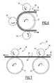
Figure 6 and 7 are diagrammatical side views of variants of the station ofFigure 5 . - The
veneer 2 illustrated onFigures 1 and 2 is a wood veneer which is for example intended to be formed and applied on a trim part, namely vehicle trim part, for imparting a positive wood aspect. - The
veneer 2 is plate shaped. Theveneer 2 comprises two opposed faces. The faces include afront face 2A intended to be visible and arear face 2B intended to be hidden. - The
veneer 2 has a uniform thickness e perpendicular to thefront face 2A andrear face 2B. The thickness e of theveneer 2 is for example equal or less than 1.5 mm, namely equal or less than 1.0 mm, preferably equal or less than 0.8 mm. - The
veneer 2 has edges delimiting the contour of theveneer 2. Theveneer 2 has for example a polygonal contour, namely a quadrangular contour. Theveneer 2 has a pair of parallel opposedfirst edges 2C and a pair of parallel opposedsecond edges 2D. Thefirst edges 2C are perpendicular to thesecond edges 2D thus imparting a rectangular contour to theveneer 2. - The
veneer 2 is initially flat and extends along a veneer plane P corresponding to the plane ofFigure 1 . - The
veneer 2 comprises at least onelignocellulosic layer 4 made oflignocellulosic fibres 6. Thelignocellulosic layer 4 is for example made of wood fibres, preferably natural wood fibres. Thelignocellulosic layer 4 is for example a sheet of wood. - Wood includes elongated wood cells including fibres, hollow fibre-vessel and/or hollow fibre-tracheid owing to the nature of the wood. The term "fibres" here designates any of these wood cells
- The
lignocellulosic fibres 6 of thelignocellulosic layer 4 extend along a general fibre line or "grain" D. Thelignocellulosic fibres 6 extend along theopposed faces veneer 2, substantially parallel to theopposed faces veneer 2. The grain D extends substantially parallel to theopposed faces veneer 2. - In the example, the
lignocellulosic fibres 6 extend parallel to thefirst edges 2C and perpendicular to thesecond edges 2D. - The
veneer 2 comprises for example one singlelignocellulosic layer 4. Alternatively theveneer 2 comprises several superimposed lignocellulosic layers. - The
veneer 2 comprises a backing layer 8 laminated on thelignocellulosic layer 4 on the side of the rear face of theveneer 2. The backing layer 8 is for example adhered to thelignocellulosic layer 4 with using an adhesive. The backing layer 8 if for example a textile, namely a woven or non woven fabric, a paper sheet, a cardboard sheet or a plastic film. - The backing layer 8 reinforces the very thin
lignocellulosic layer 4. The backing layer 8 optionally promotes bonding of theveneer 2 to a substrate. The substrate is for example a substrate made of plastic material overmolded on the rear face of theveneer 2. - The
veneer 2 optionally comprises aprotection coating 10 laminated on thelignocellulosic layer 4 on the side of the front face of theveneer 2. - The function of the
protection coating 10 is to protect thelignocellulosic layer 4 namely from UV radiations that may accelerate aging of thelignocellulosic layer 4. Theprotection coating 10 comprises one or several protection layers. Theprotection coating 10 is for example made of a synthetic resin, for example a varnish. Theprotection coating 10 is coloured, transparent or translucent. Theprotection coating 10 is for example applied on thelignocellulosic layer 4 in liquid state and dried to harden. - The
multilayer veneer 2 comprising at least one lignocellulosic layer and a backing layer 8 is generally named wood sheet complex (WSC). - In view of forming a trim part comprising a plastic substrate covered by the
veneer 2, theveneer 2 is for example shaped in three-dimension (3D) during overmoulding of the molten plastic material under pressure. -
Figure 3 illustrates steps of a method of processing theveneer 2 ofFigures 1 and 2 to increase formability of theveneer 2 that is the capacity of theveneer 2 to be easily shaped in 3D. - The method comprises at least one step of applying a compressive force on the
veneer 2 so as to compress theveneer 2 in a direction parallel to thefaces veneer 2. - The method comprises a longitudinal compression step S1 of applying a compressive force F to the
veneer 2 so as to mechanically compress thelignocellulosic fibres 6 longitudinally, that is along the grain D. - The compression is performed such as to reduce the dimension of the
veneer 2 along the grain D of about 1% to about 15%. - Optionally, the method comprises a transverse compression step S2 of applying a compressive force T to the
veneer 2 to compress the lignocellulosic fibres transversely, perpendicularly to the grain D. The compressive force T is applied on theveneer 2 parallel to thefaces - Optionally, the method comprises at least one oblique compression step of applying a compressive force to the
veneer 2 parallel to thefaces - Optionally, subsequently to a compression step, the method comprises an elongation step of applying an elongating force to the
veneer 2 opposite to the compression force applied in the compression step to restore at least partially the initial dimension of theveneer 2 in the corresponding direction. - The method comprises for example a longitudinal elongation step S3 of applying an elongating force to the
veneer 2 so as to elongate the lignocellulosic fibres longitudinally. The method comprises for example a transverse elongation step S4 of applying an elongating force to theveneer 2 so as to elongate theveneer 2 perpendicularly to the lignocellulosic fibres. - The compression steps are operated consecutively and the elongating steps are performed consecutively thereafter. In the example, as illustrated, the steps S1 through S4 are thus operated in the following sequence: S1, S2, S3, S4.
- Alternatively, a step of elongating the
veneer 2 is performed immediately after the corresponding opposite compression step. In an alternative to the example, the steps S1 through S4 are thus operated in the following sequence: S1, S3, S2, S4. - In any case, each elongating step is performed after the corresponding compression step.
- Optionally, the processing method performs compression step(s) and/or elongation step(s) on the
veneer 2 being at an adjusted temperature, preferably to a temperature comprises between -18°c to -2°c. Adjusting the temperature of theveneer 2 promotes capacity of compression and elongation by altering the microstructure of the fibres. -
Figure 4 illustrate acompression station 12 for implementing the processing method. Thecompression station 12 is configured for compressing theflat veneer 2 in a direction parallel to the plane of theveneer 2. - The
compression station 12 comprises a pair of parallelopposed rollers 14 defining between them a nip 16 for receiving theveneer 2. Therollers 14 are contra-rotative. They are coupled to a drivingunit 18 so to be rotated in opposite angular directions. - The
compression station 12 comprises astop 20 in register with thenip 16. Thestop 20 is arranged such that an edge ofveneer 2 driven through thenip 16 between therollers 14 is biased against thestop 20. - The
compression station 12 comprises a pair of parallel opposedanti-buckling plates 22 extending between thenip 16 and thestop 20 with defining between them achannel 24 for receiving theveneer 2. - Upon operation, the
veneer 2 is passed through thenip 16 such that it is pushed by therollers 14 against thestop 20 and compressed between therollers 14 and thestop 20 along a direction parallel to the opposed faces 2A, 2B of theveneer 2. Theanti-buckling plates 22 located on either sides of thecompressed veneer 2 prevent theveneer 2 from buckling. - For compressing the
veneer 2 along different directions, theveneer 2 is oriented in a first orientation and passed through thefirst compression station 12 and then pivoted in a second orientation different from the first orientation and passed again through thefirst compression station 12. Theveneer 2 is rotated about a rotation axis perpendicular to the plane P of theveneer 2. - For exerting a compressing force on the
veneer 2 ofFigure 1 and 2 so as the compress the fibres along the grain D, theveneer 2 is passed in the compression station so as to bias one of thesecond edges 2D against thestop 20 and to push the opposedsecond edge 2D received in thenip 16 towards thestop 20 with driving therollers 14, as illustrated onFigure 4 . -
Figure 5 illustrates anothercompression station 30 for implementing the processing method. - The
compression station 30 comprises acounter-pressure roller 32 and acompression roller 34 arranged parallel one to the other and defining a nip 36 for aveneer 2 to pass between thecounter-pressure roller 32 and thecompression roller 34. - The
counter-pressure roller 32 and thecompression roller 34 are driven in rotation by a drivingunit 18 such that thecounter-pressure roller 32 and thecompression roller 34 are co-rotative and rotate in the same angular direction. - The
counter-pressure roller 32 comprises arigid cylinder 38 covered by a compressibleexternal sleeve 40. Thecylinder 38 is made e.g. of metal and theexternal sleeve 40 is made e.g. of rubber, silicone or plastic. - The
counter-pressure roller 32 is provided to drive theveneer 2 passing through thenip 36. In this view, theexternal sleeve 40 is provided to adhere on therear face 2B of theveneer 2, at least more than the external surface of thecompression cylinder 34 on thefront face 2A. - In operation, the
counter-pressure roller 32 contacts therear face 2B and drives theveneer 2 in a moving direction M and thecompression roller 34 scrubs thefront face 2A of theveneer 2 opposite the moving direction M. - The
compression roller 34 has an external surface provided with projections for scrubbing thefront face 2A so as to apply on the veneer 2 a compressive force parallel to thefaces veneer 2. - In the example, projections are provided as
splines 42 separated bygrooves 44 alternating with thesplines 42 along the circumference of thecompression cylinder 34. - As illustrated on
Figure 5 , in axial view of thecompression roller 36, thesplines 42 andgrooves 44 impart a wave shaped circumferential profile. The circumferential profile is substantially sinusoidal. The height of thesplines 42 is exaggerate onFigure 5 for clarity. - In operation, a
spline 42 in contact with aveneer 2 passing in thenip 36 compresses the fibres in the region of theveneer 2 located immediately upstream thespline 42 when considering the moving direction M. - Owing to the circumferential profile of the
compression roller 34, the compressive force applied by thecompression roller 34 to theveneer 2 is not uniform along the length of the veneer. Regions of higher compression alternate with region of lesser compression along the length of the veneer. - In view of obviating this feature, a compression station comprises for example several compression rollers for applying a compression force in the same direction relative to the
veneer 2 but arranged such that the regions of higher compression of the different compression rollers are offset. - As illustrated on
Figure 6 , acompression station 30 comprisesseveral compression rollers 34 in a satellite distributed around thesame driving roller 32. Theveneer 2 is partially wound around the drivingroller 32 to pass in thenip 36 defined by eachcompression roller 34. Thecompression rollers 34 are offset such that the regions of higher compression of thedifferent compression rollers 34 are offset. - Alternatively, as illustrated on
Figure 7 , acompression station 30 comprisesseveral compression units 46 distributed along the path of theveneer 2, eachcompression unit 46 comprising a drivingroller 32 associated to acompression roller 34. Thecompression rollers 34 are offset such that the regions of higher compression of thedifferent compression rollers 34 are offset. - The direction of a compression force exerted by a
compression cylinder 34 is substantially perpendicular to the direction of extension of thesplines 42. Axial splines 42 extending parallel to the axis of thecompression roller 34 apply a compression force parallel to the moving direction M of theveneer 2. However, non rectilinear splines are conceivable. - In view of compressing the veneer in different directions along the faces of the veneer, it is possible to pass the veneer several times through a compression station with modifying the orientation of the veneer to modify the orientation of the grain D of the veneer between each passage.
- Owing to the processing method of the invention, formability of the veneer is increased, thus making it easy to impart a desired 3D shape to the veneer.
- The lignocellulosic fibres have great properties among which flexibility which impart formability of a veneer comprising a lignocellulosic layer. A lignocellulosic fibre is composed of different elements including lignin, cellulose and hemi cellulose forming a fibre elongated along a fibre axis parallel to the fibre direction of wood. The fibre comprises fibrous walls comprising fibrils extending helically around the fibre axis with various helix angles. Lignocellulosic fibres of natural wood comprise at least three fibril orientations.
- Compressing a lignocellulosic fibre along its fibre axis deforms the walls in such a manner that it imparts subsequently more flexibility to the fibre. Additionnal compression(s) transverse and/or oblique relative to the fibre axis further increases flexibility.
- The mechanical compression(s) of the lignocellulosic fibres can be detected on the veneer, even in case a corresponding elongation was performed. Indeed, the mechanical compression(s) lead to compaction and/or fragmentation of the lignocellulosic fibers. This can be detected during a microscope analysis before a heating of the veneer causing a fusion of lignin that will fill the gaps between the fragmented fibres.
- Therefore, the manufacturing process allows obtaining a veneer which comprises at least one lignocellulosic layer and which has improved formability. This enables namely to impart to the veneer a non-developable 3D shape.
- One risk upon compressing the veneer parallel to the opposed faces of the veneer is to destroy the lignocellulosic layer. Indeed, a lignocellulosic layer subjected to a compression along the grain tends to burst.
- Performing the compression on the veneer comprising the reinforcement backing layer laminated onto the lignocellulosic layer prevents the lignocellulosic layer from bursting.
- In a compression station as in
Figures 3 , the provision of anti-buckling plates assists in preventing bursting of the veneer. In a compression station as inFigure 4 , anti-buckling plates are not necessary. - Compression station or installations as in
Figures 3 - 7 are adapted for processing plates of veneer. A compression station as inFigures 4 - 7 are further adapted for continuously processing a web of veneer. Such a web is provided for example by using a continuous web of backing layer to adhere several sheets of wood successively along the web of backing layer. Veneers are cut from the web of veneer after the compression steps. - The longitudinal or oblique mechanical compression of the lignocellulosic fibres may be detected on the veneer, even in case a corresponding elongation was performed.
Claims (20)
- Method of processing a veneer (2) having two parallel opposed faces and comprising at least one lignocellulosic layer (4) made of lignocellulosic fibres (6) having a grain (D) extending along the opposed faces of the veneer (2), the method comprising applying a compressive force to the veneer (2) along at least one direction extending along the opposed faces of the veneer (2) so as to mechanically compress the lignocellulosic fibres (6).
- Method of processing a veneer according to claim 1, comprising applying a compressive force along the grain (D), applying a compressive force along at least one direction perpendicular to the grain (D) and/or applying a compressive along at least one direction oblique with respect to the grain (D).
- Method of processing a veneer according to claim 1 or 2, comprising adjusting the temperature of the veneer (2) during the step of applying a compressive force.
- Method of processing a veneer according to any preceding claim, wherein a compressive force is applied to the veneer (2) by applying one edge of the veneer (2) against a stop (20) and biasing an opposed edge of the veneer (2) towards the stop (20).
- Method of processing a veneer according to claim 4, comprising biasing the veneer (2) towards the stop (20) by passing the veneer (2) in a nip (16) between two parallel contra-rotative rollers (14).
- Method of processing a veneer according to any preceding claim, wherein a compressive force is applied to the veneer (2) by applying at least one projection (42) against a face (2A) of the veneer and moving the projection (42) along the face (2A) of the veneer (2).
- Method of processing a veneer according to claim 6, wherein projections (42) are provided on the external surface of at least one compression roller (34) applied against the face of the veneer (2), the veneer (2) being moved in a moving direction (M) relative to the compression roller (34) and the compression roller (34) being rotated to move the projections (42) in contact with the veneer (2) opposite to the moving direction (M).
- Method of processing a veneer according to claim 7, comprising a counter-pressure roller (32) defining a nip (36) with the compression roller (34), the veneer (2) being moved through the nip (36) in contact with the projections (42).
- Method of processing a veneer according to claim 8, wherein the counter-pressure roller (32) comprises a compressible external sleeve (40).
- Method of processing a veneer according to any one of claims 7 - 9, wherein the projections are provided as splines (42) alternating with grooves (44) along the circumference of the compression roller (34).
- Method of processing a veneer according to claim 10, wherein the compression roller (34) comprises axial splines.
- Method of processing a veneer according to any preceding claim, wherein the veneer (2) comprises a backing layer (8).
- Method of processing a veneer according to claim 12 wherein the backing layer (8) is chosen in the following group: a woven fabric, a non-woven fabric, a paper sheet, a cardboard sheet and a plastic sheet.
- Method of processing a veneer according to any preceding claim, wherein the veneer (2) comprises a protective layer (10).
- Method of processing a veneer according to any preceding claim, comprising applying an extension force on the veneer (2) to extend the lignocellulosic fibres (6) longitudinally.
- Method of processing a veneer according to any preceding claim, comprising forming the initially flat veneer (2) to impart a 3D shape to the veneer (2).
- Veneer having opposed faces (2A, 2B) and comprising at least one lignocellulosic layer (4) made of lignocellulosic fibres (6) extending along the opposed faces (2A, 2B), wherein the lignocellulosic fibres (6) have been subjected to a longitudinal mechanical compression, namely by a method according to anyone of the preceding claim.
- Interior trim part comprising a veneer according to claim 17.
- Veneer compression station, for processing a veneer (2) having two parallel opposed faces (2A; 2B) and comprising at least one lignocellulosic layer (4) made of lignocellulosic fibres (6) having a grain (D) extending along the opposed faces of the veneer (2), the station comprising two contra-rotative rollers (14) defining between them a nip (16) and a stop (20) located in register with the nip (16) for passing a veneer (2) through the nip (16) and biasing the veneer (2) against the stop (20) to apply a compression force on the veneer along the opposed faces of the veneer (2) so as to mechanically compress the lignocellulosic fibres (6).
- Veneer compression station, for processing a veneer (2) having two parallel opposed faces and comprising at least one lignocellulosic layer (4) made of lignocellulosic fibres (6) having a grain (D) extending along the opposed faces of the veneer (2), the station comprising two co-rotative rollers (32, 34) defining between them a nip (36), one of the rollers comprising projections (42) distributed around the circumference of the roller and arranged to contact a face (2A) of a veneer passing through the nip (36).
Priority Applications (4)
| Application Number | Priority Date | Filing Date | Title |
|---|---|---|---|
| EP13305683.8A EP2805801B1 (en) | 2013-05-24 | 2013-05-24 | Method for processing a veneer |
| US14/286,113 US10427321B2 (en) | 2013-05-24 | 2014-05-23 | Method and installations for processing a veneer and corresponding veneer |
| CN201410220548.7A CN104175377B (en) | 2013-05-24 | 2014-05-23 | For the method and apparatus for processing decoration panel and corresponding decoration panel |
| US16/506,645 US11590674B2 (en) | 2013-05-24 | 2019-07-09 | Method and installations for processing a veneer and corresponding veneer |
Applications Claiming Priority (1)
| Application Number | Priority Date | Filing Date | Title |
|---|---|---|---|
| EP13305683.8A EP2805801B1 (en) | 2013-05-24 | 2013-05-24 | Method for processing a veneer |
Publications (2)
| Publication Number | Publication Date |
|---|---|
| EP2805801A1 true EP2805801A1 (en) | 2014-11-26 |
| EP2805801B1 EP2805801B1 (en) | 2020-10-21 |
Family
ID=48576922
Family Applications (1)
| Application Number | Title | Priority Date | Filing Date |
|---|---|---|---|
| EP13305683.8A Active EP2805801B1 (en) | 2013-05-24 | 2013-05-24 | Method for processing a veneer |
Country Status (3)
| Country | Link |
|---|---|
| US (2) | US10427321B2 (en) |
| EP (1) | EP2805801B1 (en) |
| CN (1) | CN104175377B (en) |
Cited By (2)
| Publication number | Priority date | Publication date | Assignee | Title |
|---|---|---|---|---|
| US20150075733A1 (en) * | 2013-09-13 | 2015-03-19 | Faurecia Innenraum Systeme Gmbh | Roller shutter and storage compartment comprising said roller shutter |
| EP4260997A1 (en) * | 2022-04-13 | 2023-10-18 | Uniwersytet Przyrodniczy w Poznaniu | Method and device for curvilinear formation of a wodden corrugated veneer |
Families Citing this family (3)
| Publication number | Priority date | Publication date | Assignee | Title |
|---|---|---|---|---|
| DE102018127648B3 (en) | 2018-11-06 | 2020-01-16 | Novem Car Interior Design Gmbh | Process for producing a molded part |
| SE543314C2 (en) * | 2018-12-18 | 2020-11-24 | Ikea Supply Ag | A method for producing a furniture board product |
| DE102020113284A1 (en) * | 2020-05-15 | 2021-11-18 | Homann Holzwerkstoffe GmbH | Method and system for making a three-dimensionally deformed panel |
Citations (4)
| Publication number | Priority date | Publication date | Assignee | Title |
|---|---|---|---|---|
| GB501172A (en) * | 1937-01-18 | 1939-02-22 | Franz Maerkle | Process and apparatus for the manufacture of corrugated plywood |
| FR1447418A (en) * | 1965-06-17 | 1966-07-29 | Manufacturing process for reinforced timber construction elements and products obtained by this process | |
| GB1469608A (en) * | 1974-11-26 | 1977-04-06 | Hashimoto Denki Co Ltd | Core block for polywood and method and apparatus for forming same |
| EP0600232A1 (en) * | 1992-11-02 | 1994-06-08 | ALPHA INDUSTRIE DESIGN GmbH CAE/CAD/CAM Beratungsgesellschaft Projektierung und Realisierung | Method and apparatus for making cardboard packaging |
Family Cites Families (25)
| Publication number | Priority date | Publication date | Assignee | Title |
|---|---|---|---|---|
| US266163A (en) | 1882-10-17 | Railroad-signal | ||
| US266763A (en) | 1882-10-31 | John j | ||
| US839680A (en) * | 1906-02-17 | 1906-12-25 | Frank Voigt | Process of changing wood. |
| US1902032A (en) * | 1931-08-03 | 1933-03-21 | Mengel Company | Method of and apparatus for making flexible veneer |
| DE820072C (en) | 1949-02-26 | 1951-11-08 | Kurt Fellner | plywood |
| DE977090C (en) | 1953-10-13 | 1965-01-28 | Svenska Taendsticks Aktiebolag | Gluing press |
| US4139407A (en) * | 1976-09-27 | 1979-02-13 | Roland Etzold | Method and apparatus for flattening wood based panels |
| CA1092771A (en) | 1979-01-10 | 1981-01-06 | Roland Etzold | Method for flattening wood based panels and panels produced thereby |
| US4243465A (en) * | 1979-01-11 | 1981-01-06 | Ilia Gozzi | Apparatus for joining pieces of laminar material and in particular plywood core strips |
| US4356045A (en) * | 1980-05-30 | 1982-10-26 | St. Regis Paper Company | Complete production line of wood I-joist manufacturing apparatus the method of manufacture, and the I-joist product, having lumber chords and a plywood web |
| EP0068851A1 (en) | 1981-07-01 | 1983-01-05 | Union Carbide Corporation | Metallic salts of hindered phenolic anti-oxidant as anti-gel component in transition metal-catalyzed olefin polymers containing halide residue |
| US4747899A (en) * | 1986-01-31 | 1988-05-31 | Meinan Machinery Works, Inc. | Method for improving the mechanical strength of veneer sheets having lathe checks |
| SE467918B (en) * | 1987-12-01 | 1992-10-05 | Roby Teknik Ab | FLEXIBLE, SHEET OR SHAPE PACKAGING LAMINATE, SUCH TO MANUFACTURE THE LAMINATE AND THE LAMINATE PACKAGING CONTAINER MADE |
| JP2777600B2 (en) * | 1989-01-13 | 1998-07-16 | 株式会社名南製作所 | Manufacturing method of plywood with less distortion |
| US5179986A (en) * | 1990-11-15 | 1993-01-19 | Masonite Corporation | Method for improving fiberboard mat moldability |
| SE504639C2 (en) * | 1995-07-27 | 1997-03-24 | Sunds Defibrator Ind Ab | Process for continuous production of lignocellulosic discs |
| WO1999044814A1 (en) | 1998-03-02 | 1999-09-10 | Fabio Perini S.P.A. | Method and device for producing an embossed web material and product made in this way |
| JP3587436B2 (en) * | 1998-10-27 | 2004-11-10 | 松下電工株式会社 | Method of manufacturing decorative sheet and method of manufacturing decorative material |
| SE515273C2 (en) | 1999-02-01 | 2001-07-09 | Valmet Fibertech Ab | Methods and apparatus for continuous production of profiled lignocellulosic disc or strand products |
| DE60000746T2 (en) * | 1999-02-09 | 2003-03-13 | Meinan Machinery Works, Inc. | Method for transporting a sheet through a processing station |
| JP2001310419A (en) * | 2000-04-27 | 2001-11-06 | Mitsubishi Plastics Ind Ltd | Method and apparatus for manufacturing wood composite laminate |
| JP2002370208A (en) * | 2001-06-14 | 2002-12-24 | Tostem Inax Holding Ltd | Method and apparatus for manufacturing decorative laminate |
| CN101998896B (en) | 2008-04-07 | 2014-12-10 | 瓦林格创新股份有限公司 | Wood fiber based panels with a thin surface layer |
| ES2693125T3 (en) | 2008-04-07 | 2018-12-07 | Välinge Innovation AB | Method of manufacturing a floor board based on wood fiber |
| CN102756419B (en) | 2012-06-27 | 2014-05-07 | 杨明杰 | Production method for curly stacking artificial boards in bidirectional die-pressing manner |
-
2013
- 2013-05-24 EP EP13305683.8A patent/EP2805801B1/en active Active
-
2014
- 2014-05-23 CN CN201410220548.7A patent/CN104175377B/en active Active
- 2014-05-23 US US14/286,113 patent/US10427321B2/en active Active
-
2019
- 2019-07-09 US US16/506,645 patent/US11590674B2/en active Active
Patent Citations (4)
| Publication number | Priority date | Publication date | Assignee | Title |
|---|---|---|---|---|
| GB501172A (en) * | 1937-01-18 | 1939-02-22 | Franz Maerkle | Process and apparatus for the manufacture of corrugated plywood |
| FR1447418A (en) * | 1965-06-17 | 1966-07-29 | Manufacturing process for reinforced timber construction elements and products obtained by this process | |
| GB1469608A (en) * | 1974-11-26 | 1977-04-06 | Hashimoto Denki Co Ltd | Core block for polywood and method and apparatus for forming same |
| EP0600232A1 (en) * | 1992-11-02 | 1994-06-08 | ALPHA INDUSTRIE DESIGN GmbH CAE/CAD/CAM Beratungsgesellschaft Projektierung und Realisierung | Method and apparatus for making cardboard packaging |
Cited By (3)
| Publication number | Priority date | Publication date | Assignee | Title |
|---|---|---|---|---|
| US20150075733A1 (en) * | 2013-09-13 | 2015-03-19 | Faurecia Innenraum Systeme Gmbh | Roller shutter and storage compartment comprising said roller shutter |
| US10030441B2 (en) * | 2013-09-13 | 2018-07-24 | Faurecia Innenraum Systeme Gmbh | Roller shutter and storage compartment comprising said roller shutter |
| EP4260997A1 (en) * | 2022-04-13 | 2023-10-18 | Uniwersytet Przyrodniczy w Poznaniu | Method and device for curvilinear formation of a wodden corrugated veneer |
Also Published As
| Publication number | Publication date |
|---|---|
| US20190329446A1 (en) | 2019-10-31 |
| EP2805801B1 (en) | 2020-10-21 |
| US11590674B2 (en) | 2023-02-28 |
| US10427321B2 (en) | 2019-10-01 |
| CN104175377A (en) | 2014-12-03 |
| US20140349102A1 (en) | 2014-11-27 |
| CN104175377B (en) | 2018-02-27 |
Similar Documents
| Publication | Publication Date | Title |
|---|---|---|
| US11590674B2 (en) | Method and installations for processing a veneer and corresponding veneer | |
| CN110614808B (en) | Membrane with selectively weakened portions | |
| TWI781914B (en) | Manufacturing method of prepreg with cut marks | |
| RU2623255C2 (en) | Method of laminated material sheet manufacturing | |
| EP2370253B1 (en) | Waved wood assembly and method of making same | |
| EP2639047B1 (en) | Method for producing a curved profile made of composite material from a rectilinear preform of fibre layers | |
| KR101162182B1 (en) | Manufacturing apparatus for corrugated core | |
| NL2002963C2 (en) | Honeycomb panel and its production. | |
| DE19835496A1 (en) | Method and coating device for producing a composite pane and biaxially curved composite pane | |
| CN106660298B (en) | Method and device for producing a sandwich component | |
| WO2008087963A1 (en) | Process for producing flexible laminated woody material | |
| FI83406B (en) | REPARATIONSFOERFARANDE FOER EN DEFEKT TRAESKIVA. | |
| GB2485165A (en) | A laminated panel for acoustic insulation | |
| CA2938496C (en) | Thermoformable panel for shelves | |
| DE10124210A1 (en) | Hollow chambered composite plastic panel comprises three-dimensionally formed inner film with repeated structure of raised and depressed areas in both main directions and outer film faces | |
| WO2021106074A1 (en) | Molding method and molding die | |
| CN1114019C (en) | Method of manufacturing angular members consisting of flat strip sheets | |
| EP2964460A1 (en) | Reflective insulation | |
| DE102012207777A1 (en) | Producing a packaging material web based on a fibrous web, comprises rolling a first and a second fibrous web, merging the two fibrous webs with a barrier layer to form a sandwich, and compressing the two fibrous webs and the barrier layer | |
| US10131128B2 (en) | Method in which a vehicle interior trim part with a decor layer comprising paper layers is produced | |
| JP6543093B2 (en) | Panel manufacturing method | |
| KR200171747Y1 (en) | The laminated panel of the resin panel and the aluminum foil | |
| US20220184922A1 (en) | A process for making a continuous layer of at least a metallic foil of the family group of malleable/ductile metallic materials and an apparatus to carry out the process | |
| RU2415012C1 (en) | Method of producing article from polymer composite material | |
| CZ36124U1 (en) | Wood-based sandwich board with textile reinforcement layers |
Legal Events
| Date | Code | Title | Description |
|---|---|---|---|
| PUAI | Public reference made under article 153(3) epc to a published international application that has entered the european phase |
Free format text: ORIGINAL CODE: 0009012 |
|
| 17P | Request for examination filed |
Effective date: 20130524 |
|
| AK | Designated contracting states |
Kind code of ref document: A1 Designated state(s): AL AT BE BG CH CY CZ DE DK EE ES FI FR GB GR HR HU IE IS IT LI LT LU LV MC MK MT NL NO PL PT RO RS SE SI SK SM TR |
|
| AX | Request for extension of the european patent |
Extension state: BA ME |
|
| R17P | Request for examination filed (corrected) |
Effective date: 20150521 |
|
| RBV | Designated contracting states (corrected) |
Designated state(s): AL AT BE BG CH CY CZ DE DK EE ES FI FR GB GR HR HU IE IS IT LI LT LU LV MC MK MT NL NO PL PT RO RS SE SI SK SM TR |
|
| 17Q | First examination report despatched |
Effective date: 20160215 |
|
| STAA | Information on the status of an ep patent application or granted ep patent |
Free format text: STATUS: EXAMINATION IS IN PROGRESS |
|
| GRAP | Despatch of communication of intention to grant a patent |
Free format text: ORIGINAL CODE: EPIDOSNIGR1 |
|
| STAA | Information on the status of an ep patent application or granted ep patent |
Free format text: STATUS: GRANT OF PATENT IS INTENDED |
|
| INTG | Intention to grant announced |
Effective date: 20200430 |
|
| GRAJ | Information related to disapproval of communication of intention to grant by the applicant or resumption of examination proceedings by the epo deleted |
Free format text: ORIGINAL CODE: EPIDOSDIGR1 |
|
| GRAL | Information related to payment of fee for publishing/printing deleted |
Free format text: ORIGINAL CODE: EPIDOSDIGR3 |
|
| GRAS | Grant fee paid |
Free format text: ORIGINAL CODE: EPIDOSNIGR3 |
|
| STAA | Information on the status of an ep patent application or granted ep patent |
Free format text: STATUS: EXAMINATION IS IN PROGRESS |
|
| GRAR | Information related to intention to grant a patent recorded |
Free format text: ORIGINAL CODE: EPIDOSNIGR71 |
|
| STAA | Information on the status of an ep patent application or granted ep patent |
Free format text: STATUS: GRANT OF PATENT IS INTENDED |
|
| GRAA | (expected) grant |
Free format text: ORIGINAL CODE: 0009210 |
|
| STAA | Information on the status of an ep patent application or granted ep patent |
Free format text: STATUS: THE PATENT HAS BEEN GRANTED |
|
| INTC | Intention to grant announced (deleted) | ||
| AK | Designated contracting states |
Kind code of ref document: B1 Designated state(s): AL AT BE BG CH CY CZ DE DK EE ES FI FR GB GR HR HU IE IS IT LI LT LU LV MC MK MT NL NO PL PT RO RS SE SI SK SM TR |
|
| INTG | Intention to grant announced |
Effective date: 20200914 |
|
| REG | Reference to a national code |
Ref country code: GB Ref legal event code: FG4D |
|
| REG | Reference to a national code |
Ref country code: CH Ref legal event code: EP |
|
| REG | Reference to a national code |
Ref country code: DE Ref legal event code: R096 Ref document number: 602013073426 Country of ref document: DE |
|
| REG | Reference to a national code |
Ref country code: IE Ref legal event code: FG4D |
|
| REG | Reference to a national code |
Ref country code: AT Ref legal event code: REF Ref document number: 1325377 Country of ref document: AT Kind code of ref document: T Effective date: 20201115 |
|
| REG | Reference to a national code |
Ref country code: AT Ref legal event code: MK05 Ref document number: 1325377 Country of ref document: AT Kind code of ref document: T Effective date: 20201021 |
|
| REG | Reference to a national code |
Ref country code: NL Ref legal event code: MP Effective date: 20201021 |
|
| PG25 | Lapsed in a contracting state [announced via postgrant information from national office to epo] |
Ref country code: NO Free format text: LAPSE BECAUSE OF FAILURE TO SUBMIT A TRANSLATION OF THE DESCRIPTION OR TO PAY THE FEE WITHIN THE PRESCRIBED TIME-LIMIT Effective date: 20210121 Ref country code: PT Free format text: LAPSE BECAUSE OF FAILURE TO SUBMIT A TRANSLATION OF THE DESCRIPTION OR TO PAY THE FEE WITHIN THE PRESCRIBED TIME-LIMIT Effective date: 20210222 Ref country code: NL Free format text: LAPSE BECAUSE OF FAILURE TO SUBMIT A TRANSLATION OF THE DESCRIPTION OR TO PAY THE FEE WITHIN THE PRESCRIBED TIME-LIMIT Effective date: 20201021 Ref country code: RS Free format text: LAPSE BECAUSE OF FAILURE TO SUBMIT A TRANSLATION OF THE DESCRIPTION OR TO PAY THE FEE WITHIN THE PRESCRIBED TIME-LIMIT Effective date: 20201021 Ref country code: FI Free format text: LAPSE BECAUSE OF FAILURE TO SUBMIT A TRANSLATION OF THE DESCRIPTION OR TO PAY THE FEE WITHIN THE PRESCRIBED TIME-LIMIT Effective date: 20201021 Ref country code: GR Free format text: LAPSE BECAUSE OF FAILURE TO SUBMIT A TRANSLATION OF THE DESCRIPTION OR TO PAY THE FEE WITHIN THE PRESCRIBED TIME-LIMIT Effective date: 20210122 |
|
| REG | Reference to a national code |
Ref country code: LT Ref legal event code: MG4D |
|
| PG25 | Lapsed in a contracting state [announced via postgrant information from national office to epo] |
Ref country code: PL Free format text: LAPSE BECAUSE OF FAILURE TO SUBMIT A TRANSLATION OF THE DESCRIPTION OR TO PAY THE FEE WITHIN THE PRESCRIBED TIME-LIMIT Effective date: 20201021 Ref country code: LV Free format text: LAPSE BECAUSE OF FAILURE TO SUBMIT A TRANSLATION OF THE DESCRIPTION OR TO PAY THE FEE WITHIN THE PRESCRIBED TIME-LIMIT Effective date: 20201021 Ref country code: SE Free format text: LAPSE BECAUSE OF FAILURE TO SUBMIT A TRANSLATION OF THE DESCRIPTION OR TO PAY THE FEE WITHIN THE PRESCRIBED TIME-LIMIT Effective date: 20201021 Ref country code: IS Free format text: LAPSE BECAUSE OF FAILURE TO SUBMIT A TRANSLATION OF THE DESCRIPTION OR TO PAY THE FEE WITHIN THE PRESCRIBED TIME-LIMIT Effective date: 20210221 Ref country code: ES Free format text: LAPSE BECAUSE OF FAILURE TO SUBMIT A TRANSLATION OF THE DESCRIPTION OR TO PAY THE FEE WITHIN THE PRESCRIBED TIME-LIMIT Effective date: 20201021 Ref country code: AT Free format text: LAPSE BECAUSE OF FAILURE TO SUBMIT A TRANSLATION OF THE DESCRIPTION OR TO PAY THE FEE WITHIN THE PRESCRIBED TIME-LIMIT Effective date: 20201021 Ref country code: BG Free format text: LAPSE BECAUSE OF FAILURE TO SUBMIT A TRANSLATION OF THE DESCRIPTION OR TO PAY THE FEE WITHIN THE PRESCRIBED TIME-LIMIT Effective date: 20210121 |
|
| PG25 | Lapsed in a contracting state [announced via postgrant information from national office to epo] |
Ref country code: HR Free format text: LAPSE BECAUSE OF FAILURE TO SUBMIT A TRANSLATION OF THE DESCRIPTION OR TO PAY THE FEE WITHIN THE PRESCRIBED TIME-LIMIT Effective date: 20201021 |
|
| REG | Reference to a national code |
Ref country code: DE Ref legal event code: R097 Ref document number: 602013073426 Country of ref document: DE |
|
| PG25 | Lapsed in a contracting state [announced via postgrant information from national office to epo] |
Ref country code: RO Free format text: LAPSE BECAUSE OF FAILURE TO SUBMIT A TRANSLATION OF THE DESCRIPTION OR TO PAY THE FEE WITHIN THE PRESCRIBED TIME-LIMIT Effective date: 20201021 Ref country code: SK Free format text: LAPSE BECAUSE OF FAILURE TO SUBMIT A TRANSLATION OF THE DESCRIPTION OR TO PAY THE FEE WITHIN THE PRESCRIBED TIME-LIMIT Effective date: 20201021 Ref country code: LT Free format text: LAPSE BECAUSE OF FAILURE TO SUBMIT A TRANSLATION OF THE DESCRIPTION OR TO PAY THE FEE WITHIN THE PRESCRIBED TIME-LIMIT Effective date: 20201021 Ref country code: CZ Free format text: LAPSE BECAUSE OF FAILURE TO SUBMIT A TRANSLATION OF THE DESCRIPTION OR TO PAY THE FEE WITHIN THE PRESCRIBED TIME-LIMIT Effective date: 20201021 Ref country code: EE Free format text: LAPSE BECAUSE OF FAILURE TO SUBMIT A TRANSLATION OF THE DESCRIPTION OR TO PAY THE FEE WITHIN THE PRESCRIBED TIME-LIMIT Effective date: 20201021 Ref country code: SM Free format text: LAPSE BECAUSE OF FAILURE TO SUBMIT A TRANSLATION OF THE DESCRIPTION OR TO PAY THE FEE WITHIN THE PRESCRIBED TIME-LIMIT Effective date: 20201021 |
|
| PLBE | No opposition filed within time limit |
Free format text: ORIGINAL CODE: 0009261 |
|
| STAA | Information on the status of an ep patent application or granted ep patent |
Free format text: STATUS: NO OPPOSITION FILED WITHIN TIME LIMIT |
|
| PG25 | Lapsed in a contracting state [announced via postgrant information from national office to epo] |
Ref country code: DK Free format text: LAPSE BECAUSE OF FAILURE TO SUBMIT A TRANSLATION OF THE DESCRIPTION OR TO PAY THE FEE WITHIN THE PRESCRIBED TIME-LIMIT Effective date: 20201021 |
|
| 26N | No opposition filed |
Effective date: 20210722 |
|
| PG25 | Lapsed in a contracting state [announced via postgrant information from national office to epo] |
Ref country code: AL Free format text: LAPSE BECAUSE OF FAILURE TO SUBMIT A TRANSLATION OF THE DESCRIPTION OR TO PAY THE FEE WITHIN THE PRESCRIBED TIME-LIMIT Effective date: 20201021 |
|
| PG25 | Lapsed in a contracting state [announced via postgrant information from national office to epo] |
Ref country code: SI Free format text: LAPSE BECAUSE OF FAILURE TO SUBMIT A TRANSLATION OF THE DESCRIPTION OR TO PAY THE FEE WITHIN THE PRESCRIBED TIME-LIMIT Effective date: 20201021 |
|
| REG | Reference to a national code |
Ref country code: CH Ref legal event code: PL |
|
| GBPC | Gb: european patent ceased through non-payment of renewal fee |
Effective date: 20210524 |
|
| PG25 | Lapsed in a contracting state [announced via postgrant information from national office to epo] |
Ref country code: CH Free format text: LAPSE BECAUSE OF NON-PAYMENT OF DUE FEES Effective date: 20210531 Ref country code: LU Free format text: LAPSE BECAUSE OF NON-PAYMENT OF DUE FEES Effective date: 20210524 Ref country code: MC Free format text: LAPSE BECAUSE OF FAILURE TO SUBMIT A TRANSLATION OF THE DESCRIPTION OR TO PAY THE FEE WITHIN THE PRESCRIBED TIME-LIMIT Effective date: 20201021 Ref country code: LI Free format text: LAPSE BECAUSE OF NON-PAYMENT OF DUE FEES Effective date: 20210531 |
|
| REG | Reference to a national code |
Ref country code: BE Ref legal event code: MM Effective date: 20210531 |
|
| PG25 | Lapsed in a contracting state [announced via postgrant information from national office to epo] |
Ref country code: IE Free format text: LAPSE BECAUSE OF NON-PAYMENT OF DUE FEES Effective date: 20210524 Ref country code: GB Free format text: LAPSE BECAUSE OF NON-PAYMENT OF DUE FEES Effective date: 20210524 |
|
| PG25 | Lapsed in a contracting state [announced via postgrant information from national office to epo] |
Ref country code: IS Free format text: LAPSE BECAUSE OF FAILURE TO SUBMIT A TRANSLATION OF THE DESCRIPTION OR TO PAY THE FEE WITHIN THE PRESCRIBED TIME-LIMIT Effective date: 20210221 |
|
| PG25 | Lapsed in a contracting state [announced via postgrant information from national office to epo] |
Ref country code: BE Free format text: LAPSE BECAUSE OF NON-PAYMENT OF DUE FEES Effective date: 20210531 |
|
| PG25 | Lapsed in a contracting state [announced via postgrant information from national office to epo] |
Ref country code: HU Free format text: LAPSE BECAUSE OF FAILURE TO SUBMIT A TRANSLATION OF THE DESCRIPTION OR TO PAY THE FEE WITHIN THE PRESCRIBED TIME-LIMIT; INVALID AB INITIO Effective date: 20130524 |
|
| PG25 | Lapsed in a contracting state [announced via postgrant information from national office to epo] |
Ref country code: CY Free format text: LAPSE BECAUSE OF FAILURE TO SUBMIT A TRANSLATION OF THE DESCRIPTION OR TO PAY THE FEE WITHIN THE PRESCRIBED TIME-LIMIT Effective date: 20201021 |
|
| PG25 | Lapsed in a contracting state [announced via postgrant information from national office to epo] |
Ref country code: MK Free format text: LAPSE BECAUSE OF FAILURE TO SUBMIT A TRANSLATION OF THE DESCRIPTION OR TO PAY THE FEE WITHIN THE PRESCRIBED TIME-LIMIT Effective date: 20201021 |
|
| PG25 | Lapsed in a contracting state [announced via postgrant information from national office to epo] |
Ref country code: TR Free format text: LAPSE BECAUSE OF FAILURE TO SUBMIT A TRANSLATION OF THE DESCRIPTION OR TO PAY THE FEE WITHIN THE PRESCRIBED TIME-LIMIT Effective date: 20201021 |
|
| PG25 | Lapsed in a contracting state [announced via postgrant information from national office to epo] |
Ref country code: MT Free format text: LAPSE BECAUSE OF FAILURE TO SUBMIT A TRANSLATION OF THE DESCRIPTION OR TO PAY THE FEE WITHIN THE PRESCRIBED TIME-LIMIT Effective date: 20201021 |
|
| PGFP | Annual fee paid to national office [announced via postgrant information from national office to epo] |
Ref country code: DE Payment date: 20250423 Year of fee payment: 13 |
|
| PGFP | Annual fee paid to national office [announced via postgrant information from national office to epo] |
Ref country code: IT Payment date: 20250423 Year of fee payment: 13 |
|
| PGFP | Annual fee paid to national office [announced via postgrant information from national office to epo] |
Ref country code: FR Payment date: 20250423 Year of fee payment: 13 |