EP2805798B1 - System with adjustable compression, adjustable tension rod indicator, and adjustable extension rod - Google Patents
System with adjustable compression, adjustable tension rod indicator, and adjustable extension rod Download PDFInfo
- Publication number
- EP2805798B1 EP2805798B1 EP14167560.3A EP14167560A EP2805798B1 EP 2805798 B1 EP2805798 B1 EP 2805798B1 EP 14167560 A EP14167560 A EP 14167560A EP 2805798 B1 EP2805798 B1 EP 2805798B1
- Authority
- EP
- European Patent Office
- Prior art keywords
- tension
- compression
- rod assembly
- rod
- shaft
- Prior art date
- Legal status (The legal status is an assumption and is not a legal conclusion. Google has not performed a legal analysis and makes no representation as to the accuracy of the status listed.)
- Active
Links
Images


Classifications
-
- F—MECHANICAL ENGINEERING; LIGHTING; HEATING; WEAPONS; BLASTING
- F16—ENGINEERING ELEMENTS AND UNITS; GENERAL MEASURES FOR PRODUCING AND MAINTAINING EFFECTIVE FUNCTIONING OF MACHINES OR INSTALLATIONS; THERMAL INSULATION IN GENERAL
- F16F—SPRINGS; SHOCK-ABSORBERS; MEANS FOR DAMPING VIBRATION
- F16F1/00—Springs
-
- B—PERFORMING OPERATIONS; TRANSPORTING
- B25—HAND TOOLS; PORTABLE POWER-DRIVEN TOOLS; MANIPULATORS
- B25B—TOOLS OR BENCH DEVICES NOT OTHERWISE PROVIDED FOR, FOR FASTENING, CONNECTING, DISENGAGING OR HOLDING
- B25B5/00—Clamps
- B25B5/04—Clamps with pivoted jaws
-
- B—PERFORMING OPERATIONS; TRANSPORTING
- B25—HAND TOOLS; PORTABLE POWER-DRIVEN TOOLS; MANIPULATORS
- B25B—TOOLS OR BENCH DEVICES NOT OTHERWISE PROVIDED FOR, FOR FASTENING, CONNECTING, DISENGAGING OR HOLDING
- B25B5/00—Clamps
- B25B5/06—Arrangements for positively actuating jaws
- B25B5/12—Arrangements for positively actuating jaws using toggle links
-
- B—PERFORMING OPERATIONS; TRANSPORTING
- B25—HAND TOOLS; PORTABLE POWER-DRIVEN TOOLS; MANIPULATORS
- B25B—TOOLS OR BENCH DEVICES NOT OTHERWISE PROVIDED FOR, FOR FASTENING, CONNECTING, DISENGAGING OR HOLDING
- B25B5/00—Clamps
- B25B5/16—Details, e.g. jaws, jaw attachments
-
- B—PERFORMING OPERATIONS; TRANSPORTING
- B25—HAND TOOLS; PORTABLE POWER-DRIVEN TOOLS; MANIPULATORS
- B25J—MANIPULATORS; CHAMBERS PROVIDED WITH MANIPULATION DEVICES
- B25J15/00—Gripping heads and other end effectors
- B25J15/0028—Gripping heads and other end effectors with movable, e.g. pivoting gripping jaw surfaces
Definitions
- the present disclosure relates generally to the controlling of an object through the use of adjustable compression and tension based on indications of compression and tension.
- the present invention relates to a system according to the preamble of claim 1 and a method of using the system of claim 1 for employing an object configured to apply a biasing force, the object being compressed and extended by rods whose position may be fixed, in conjunction with a device that may clamp and hold the captured object with a known pressure.
- FR 2982516 A1 describes a known system with a movable elastic rod comprising a biasing unit axially arranged between a claiming body and the rod.
- Compression rods, tension rods, and extension rods are used for many purposes, including retaining and stabilizing an object.
- known devices include shock absorbers, spring loaded clamping devices, and coupling nut devices. Shock absorbers control an amount of compression to known objects while reducing extension recovery time. Shock absorbers smooth out and damp shock impulse as well as dissipate kinetic energy. Spring loaded clamping devices support the holding of an object in place by exerting over forces or under forces or spring actuated forces.
- Coupling nut devices are used to create extended rod assemblies from shorter lengths of rods.
- Coupling nut devices may use a threaded fastener to join two male threads, commonly known as externally threaded rods. By drawing two threaded male rods closer together or driving them farther apart, an overall length of the combined two rods and coupling nut device may be fixed and known. More than one coupling nut device may be used with a plurality of threaded male rods, to create a rod assembly of more extended length.
- Tension rods have a variety of applications wherein ends of a rod are forced outward to press against fixed surfaces.
- Curtain rods containing springs that install into window frames or shower stalls without a need for fixed hanging hardware are examples of domestic uses of tension rods.
- Load cells and limit switches are used in applying compression and tension in industrial applications. Load cells are transducers that convert force into electrical signals. Limit switches are operated by the motion of a machine part or presence of an object. They are used for control of a machine, as safety interlocks, or to count objects passing a point. Standardized limit switches are industrial control components that may be operated by the motion of the operating lever. Gas cylinders, gas struts, and various hydraulic devices are also used in applications requiring compression and tension.
- FR2982516 describes a system for clamping a metal sheet with an actuator and a calibrated spring for applying a predetermined force.
- the illustrative embodiments provide for a system comprising a rod assembly.
- the rod assembly comprises a biasing device that returns to a rest position when the biasing device is subjected to one of a first compression by a first object and a first tension by a second object in which the first tension causes a second compression of a third object, in which the first compression causes a second tension of the third object, in which elongation of the rod assembly simultaneously occurs with the first tension and the second compression, and in which elongation of the rod assembly simultaneously occurs with the second tension and the first compression.
- the illustrative embodiments also provide for an apparatus.
- the apparatus comprises an apparatus with adjustable compression, tension, and extension.
- the apparatus comprises a housing component comprising a hollow tube, a compression rod configured to insert partially inside a first end of the housing component, and a coupling nut attached to the compression rod, the coupling nut configured to affix a position of the compression rod relative to the housing component.
- the apparatus also comprises a tension rod configured for partial insertion inside a second end of the housing component and a biasing device configured for placement inside the housing component between and attached to the tension rod and the compression rod. Adjustments to positioning of at least one of the compression rod and the tension rod relative to the housing component alter compression and tension of the biasing device and cause the apparatus to respectively one of push and pull devices contacting the apparatus.
- the illustrative embodiments also provide for a method for controlling an amount of force required to retain and release at least one object through clamping and holding.
- the method comprises attaching a rod assembly to a clamping device, the clamping device comprising jaws for applying one of a first tension and a first compression to an object, the clamping device further comprising a handle in which pulling the handle causes the jaws to apply the first compression to the object, and in which pushing the handle causes the jaws to apply the first tension to the object.
- the method also comprises turning a coupling nut on a first shaft of the rod assembly to set a second tension of a biasing device in the rod assembly until the second tension is exhibited on markers displayed on a second shaft of the rod assembly, the second tension causing a second compression against the object when the handle is pulled.
- the method also comprises turning the first shaft in the rod assembly to set a third compression exerted by the rod assembly, the third compression exerted by the rod assembly causing a third tension against the object when the handle is pushed in which turning the coupling nut additionally adjusts length of the rod assembly simultaneous with setting the second tension and the second compression and simultaneous with setting the third compression and the third tension.
- the illustrative embodiments also provide for a method comprising simultaneously applying, using only a single rod assembly, compression, tension, and elongation of the single rod assembly to a tool connected to the single rod assembly.
- a first adjustment to a first position of the first shaft in relation to the tubular housing component results in a compression of the third object and wherein a second adjustment to a second position of the second shaft in relation to the tubular housing component results in a third tension of the object.
- the biasing device is an elastic device.
- the biasing device is an elastomeric device.
- the biasing device is a spring with a known elastic force property; and wherein the known elastic force property is a spring constant.
- the rod assembly is used in conjunction with a clamping device; and wherein the clamping device applies the second compression to the object and applies the second tension to the object.
- the second shaft is calibrated to the spring constant; and wherein a level of tension exerted on the spring is determined from observing a length of the second shaft protruding outside the tubular housing component.
- first shaft and the second shaft are placed at opposite ends of the biasing device.
- the biasing device is a spring.
- the markers displayed on the second shaft are calibrated to a spring constant of the biasing device.
- the illustrative embodiments recognize and take into account the issues described above, with respect to providing adjustable and fixable compression and tension for a rod assembly with adjustable length.
- the illustrative embodiments relate to systems and methods wherein one of tension and compression by the system provided herein may be affixed and held constant.
- the system provides methods for controlling an amount of force required to retain and release an object or objects through clamping and holding. Controlling such required amount of force may be accomplished through using an adjustable tension indication portion of the rod assembly.
- the illustrative embodiments also provide for controlling an amount of force required to retain or release an object or objects through a portion of the rod assembly that applies adjustable compression.
- the system also allows setting the desired extension of the rod assembly.
- the illustrative embodiments recognize that fragile objects may need to be grasped, clamped, lifted, and in some cases moved. Some objects may, for example, contain sensitive electronic parts. Effectively and safely grasping such objects may require applying an amount of grasping force that is adequate to take and maintain hold of such objects without risking dropping the objects, while at the same time not applying excessive grasping force that may damage the objects.
- the rod assembly of the present disclosure includes a tubular housing that contains a biasing device with an elastic property.
- the biasing device may be a spring.
- the spring may be both compressible and stretchable.
- a level of compression may be set.
- a second rod, or tension rod, that may not be threaded slides into an opposite or non-threaded end of the tubular housing and attach to the opposite end of the spring.
- the spring may have a known spring constant.
- the tension rod may be calibrated to the spring constant.
- stripes or other indicia on the tension rod that are calibrated to the spring constant of the spring may be visible. These indicia may indicate the amount of tension or pulling force on the entire device.
- Screws or similar components may be placed in the tubular housing, a compression rod, the tension rod, or the coupling nut. These components may promote the device to remain rigid and maintain a desired level of compression or tension depending respectively on whether the spring has been pushed or pulled.
- the illustrative embodiments further provide for the threaded end of the tubular housing, the coupling nut, and the threaded compression rod to be used together to adjust the overall length of the rod assembly. Compression is controlled by back tension on the spring by the compression rod in the tubular housing.
- the compression rod, and the coupling nut might not be threaded and instead may bind to each other using components and methods other than threading.
- the illustrative embodiments further contemplate that the rod assembly is used in conjunction with a clamping mechanism or device. Such a device clamps and maintains hold of the object of interest.
- the rod assembly is attached to the clamping device, such that the amount of tension or compression provided by the rod assembly directly bears upon an amount of pressure that the clamping device places against the object.
- Ends of the compression rod and the tension rod may be fitted into components of a clamping device associated with opening and closing the device on an object.
- a compression or tension may be set for the rod assembly.
- the rod assembly then may attach to handles or other components of the clamping device that control closing and opening jaws that grasp and release the object.
- the illustrative embodiments further recognize that while the rod assembly of the present disclosure may be used in applications for applying pressure against an object that is being grasped and released, the rod assembly may be used in other applications. Such applications may call for the control of an amount of force wherein grasping or clamping is not involved.
- Figure 1 is a block diagram of a rod assembly in accordance with an illustrative embodiment.
- System 100 includes rod assembly 102.
- Rod assembly 102 includes biasing device 104, first object 106, and second object 108.
- Biasing device 104 returns to a rest position when biasing device 104 is subjected to a first compression by first object 106.
- Biasing device 104 also returns to rest position when biasing device 104 is subjected to a first tension by second object 108.
- System 100 also includes third object 110 that is not a component of rod assembly 102.
- Third object 110 is subjected to forces created in part by rod assembly 102.
- First tension causes a second compression of third object 110.
- First compression causes a second tension of third object 110.
- Elongation of rod assembly 102 simultaneously occurs with first tension and second compression.
- Elongation of rod assembly 102 simultaneously occurs with second tension and first compression.
- FIG. 2 is a block diagram of system 200 of a rod assembly 202 depicted in accordance with an illustrative embodiment.
- System 200 includes biasing device 204 .
- biasing device 204 may be a spring. While the term “biasing device 204 " is used herein to indicate an object that both compresses and stretches, in other embodiments, biasing device 204 may not be a spring and may instead be another object with biasing force properties that urge biasing device 204 back to a rest position once biasing device 204 is one of stretched and compressed. Biasing device 204 may have components at each end permitting biasing device 204 to be grasped. Biasing device 204 may be composed of a metallic material, but may be another material such as a non-metallic material. Biasing device 204, if a spring, may have a known spring constant.
- System 200 also includes compression rod 206 and tension rod 208 that attach to biasing device 204 at opposite ends of biasing device 204.
- Compression rod 206 pushes upon or applies compression to biasing device 204.
- Tension rod 208 pulls or applies tension to biasing device 204.
- System 200 also includes clamping device 212 that uses rod assembly 202 to implement adjustments in applying pressure.
- System 200 also includes object 210 which is grasped and released by clamping device 212. Amounts of compression and tension applied by clamping device 212 against object 210 are affected by adjustments to components of rod assembly 202 when rod assembly 202 is being used in conjunction with clamping device 212.
- rod assembly 202 is attached to clamping device 212 and used by clamping device 212 to implement changes in pressure against object 210.
- Rod assembly 202 may be used in manners entirely unrelated to clamping and releasing an object. Rod assembly 202 may apply compression, tension, and elongation in applications and embodiments that do not involve clamping device 212, object 210, and the actions of applying and releasing pressure on an object.
- System 200 also includes housing 214 that is a component of rod assembly 202.
- Housing 214 is a hollow, tubular structure that is internally threaded at one or more ends.
- housing 214 is made of a metallic material.
- Housing 214 may, in other embodiments, be made of non-metallic material, for example, a plastic or a composite material.
- System 200 also may include screw 216 and screw 218 that screw into housing 214 and affix components inside housing 214 into place to maintain rigidity of rod assembly 202.
- Compression rod 206 is externally threaded and screws partially into an internally threaded end of housing 214 .
- Compression rod 206 attaches to biasing device 204 inside housing 214.
- Compression rod 206 pushes or pulls biasing device 204 to respectively compress or stretch biasing device 204.
- compression rod 206 may include a mechanism for attaching to biasing device 204, thereby facilitating the pulling or pushing of biasing device 204.
- System 200 also may include coupling nut 220 that may be internally threaded and may screw onto compression rod 206. Coupling nut 220 may be used to assist in turning compression rod 206, while compression rod 206 screws in or out of housing 214. Turning compression rod 206 may result in compression or tension of biasing device 204. Moving coupling nut 220 may also change the overall length of rod assembly 202. In an embodiment, compression rod 206 may include two separate, externally threaded rods joined by coupling nut 220, a configuration that may facilitate changing the overall length of rod assembly 202.
- System 200 also may include pin 222 and pin 224 that insert into coupling nut 220 in a perpendicular or other manner to affix coupling nut 220 in place.
- pin 222 and pin 224 may be inserted into holes in a side of coupling nut 220.
- Pin 222 and pin 224 may slide, screw, or otherwise pass through the holes until pin 222 and pin 224 make firm contact with compression rod 206 and effectively lock coupling nut 220 to compression rod 206 and thus prevent coupling nut 220 from turning. Actions of pin 222 and pin 224 may prevent changes in the overall length of rod assembly 202 as well as changes to a tension on biasing device 204. While pin 222 and pin 224 are provided herein, in other embodiments, system 200 may be only one pin or may comprise three or more pins. Other types of stops might be used. In an embodiment, a second coupling nut may screw onto compression rod 206 against coupling nut 220 to tighten against coupling nut 220.
- Tension rod 208 slides partially inside housing 214 and attaches to end 226 of biasing device 204 that is opposite end 228 of biasing device 204 attached to compression rod 206. Tension rod 208 slides into end 230 of housing 214 that is not internally threaded.
- tension rod 208 is calibrated with visible band 232, band 234, and band 236 that may vary in color or other manner of indication between levels of calibration. Band 232, band 234, and band 236 may be calibrated to a spring constant of biasing device 204.
- band 232, band 234, and band 236 may visibly indicate an increasing amount of tension on biasing device 204.
- band 232, band 234, and band 236 may appear in successive order. Appearance of each of band 232, band 234, and band 236 as tension rod 208 pulls out increasingly far may indicate an increasing level of tension on biasing device 204.
- appearance of band 232 as tension rod 208 is pulled may indicate a first level of tension on biasing device 204.
- Appearance of band 232 and band 234 as tension rod 208 is pulled out further may indicate a second level of tension on biasing device 204. Appearance of band 232, band 234, and band 236 as tension rod 208 is pulled out even further may indicate yet a third level of tension on biasing device 204.
- the second level of tension is higher than first level of tension.
- the third level of tension is higher than second level of tension and first level of tension.
- Biasing device 204 is depicted in Figure 2 using a dotted line to indicate that biasing device 204 is inside housing 214. Portions of compression rod 206 and tension rod 208 that are inside housing 214 are also depicted using dotted lines.
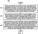
- Figure 3 is a flowchart of a method for controlling an amount of force required to retain and release at least one object through clamping and holding in accordance with an illustrative embodiment.
- Method 300 shown in Figure 3 may be implemented using system 100 of Figure 1 and system 200 of Figure 2 .
- the process depicted in Figure 3 may be a variation of the processes discussed in connection with Figure 1 , with Figure 2 and with Figure 4 through Figure 22 .
- the operations presented in Figure 3 are described as being performed by "a process,” the operations may be performed using one or more physical devices, as described elsewhere herein.
- the "process" may be one or more human users.
- Method 300 may begin as the process attaches rod assembly 202 to clamping device 212, clamping device 212 including jaws for applying one of a first compression and a first tension to object 210, clamping device 212 further including a handle in which pulling handle causes jaws to apply the first compression to object 210, and in which pushing handle causes jaws to apply the first tension to object 210 (operation 302). Jaws and handle of clamping device 212 are described in detail herein in discussion of Figure 12 through Figure 18 .
- the process may then turn coupling nut 220 on a first shaft that may be compression rod 206 of rod assembly 202 to set a second tension of biasing device 204 in rod assembly 202 until second tension is exhibited on markers that may be band 232, band 234, and band 236 displayed on a second shaft that may be tension rod 208, second tension causing a second compression against object 210 when handle is pulled (operation 304).
- the process may then turn the first shaft in rod assembly 202 to set a third compression exerted by rod assembly 202, third compression exerted by rod assembly 202 causing a third tension against object 210 when handle is pushed in which turning coupling nut 220 additionally adjusts length of rod assembly 202 simultaneous with setting second tension and second compression and simultaneous with setting third compression and third tension (operation 306).
- Tension rod 208 has end 238 and compression rod 206 has end 240 that are not inside housing 214 and are at far ends of rod assembly 202.
- Each of end 238 and end 240 may have tabs with holes or other openings that permit attachment of rod assembly 202 to other devices, including clamping device 212.
- compression rod 206 may comprise two separate components that are joined by coupling nut 220, an arrangement that may support greater flexibility in extending overall length of rod assembly.
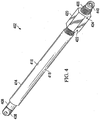
- Figure 4 depicts rod assembly 402 in accordance with an illustrative embodiment. Components shown in Figure 4 through Figure 11 are indexed to components in Figure 1 and Figure 2 .
- Rod assembly 402 shown in Figure 4 corresponds to rod assembly 102 sown in Figure 1 and rod assembly 202 shown in Figure 2 .
- Compression rod 406 shown in Figure 4 corresponds to first object 106 shown in Figure 1 and compression rod 206 shown in Figure 2 .
- Tension rod 408 shown in Figure 4 corresponds to second object 108 shown in Figure 1 and tension rod 208 shown in Figure 2 .
- Housing 414 shown in Figure 4 corresponds to housing 214 shown in Figure 2 .
- Screw 416 and screw 418 shown in Figure 4 correspond to screw 216 and screw 218, respectively, shown in Figure 2 .
- Coupling nut 420 shown in Figure 4 corresponds to coupling nut 220 shown in Figure 2 .
- Pin 422 and pin 424 shown in Figure 4 correspond to pin 222 and pin 224, respectively, shown in Figure 2 .
- End 438 and end 440 shown in Figure 4 correspond to end 238 and end 240, respectively, shown in Figure 2 .
- Rod assembly 402 in Figure 4 is depicted with compression rod 406 and tension rod 408 placed relatively far inside housing 414 of Figure 4 .
- End 438 is part of tension rod 408 and may attach to clamping device 212 shown in Figure 2 .
- End 440 is part of compression rod 406 and may also attach to clamping device 212 shown in Figure 2 .
- end 438 and end 440 may be clevis fasteners.
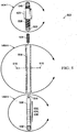
- Figure 5 depicts an exploded rod assembly in accordance with an illustrative embodiment, with an exploded view of components of the rod assembly. As with components of Figure 4 , components of Figure 5 are indexed to components of Figure 1 and Figure 2 .
- Rod assembly 502 shown in Figure 5 corresponds to rod assembly 102 shown in Figure 1 and rod assembly 202 shown in Figure 2 .
- Biasing device 504 shown in Figure 5 corresponds to biasing device 104 shown in Figure 1 and biasing device 204 shown in Figure 2 .
- Compression rod 506 shown in Figure 5 corresponds to first object 106 shown in Figure 1 and compression rod 206 shown in Figure 2 .
- Tension rod 508 shown in Figure 5 corresponds to second object 108 shown in Figure 1 and tension rod 208 shown in Figure 2 .
- Housing 514 shown in Figure 5 corresponds to housing 214 shown in Figure 2 .
- Screw 516 and screw 518 shown in Figure 5 correspond to screw 216 and screw 218, respectively, shown in Figure 2 .
- Coupling nut 520 shown in Figure 5 corresponds to coupling nut 220 shown in Figure 2 .
- Band 532, band 534, and band 536 shown in Figure 5 correspond to band 232, band 234, and band 236, respectively, shown in Figure 2 .
- End 538 and end 540 shown in Figure 5 correspond to end 238 and end 240, respectively, shown in Figure 2 .
- Figure 5 depicts swivel hook 550 attached to end of compression rod 506 .
- Swivel hook 550 attaches to biasing device 504 and swivels so as not to twist biasing device 504 during turning of compression rod 506.
- Figure 5 also shows eyelet 544, which attaches to tension rod 508 and attaches to biasing device 504. While discussion herein of Figure 5 enumerates band 532, band 534, and band 536, Figure 5 provides a depiction of more than three bands for illustration and discussion purposes. The provision of three bands in Figure 2 was purely for discussion purposes.
- rod assembly 202 may have no bands or one or two bands. In an embodiment, rod assembly 202 may have more than three bands.
- Figure 5 also depicts three semicircles surrounding components of Figure 5 .
- the semicircles referred to hereinafter as views, surround components of Figure 5 to be discussed in association with subsequent figures.
- a first semicircle denoted as View 5 encompasses tension rod 508 and associated components.
- a second semicircle denoted as View 6, encompasses housing 514 and associated components.
- a third semicircle denoted as View 7, encompasses compression rod 506 and associated components.
- Figure 6 depicts selected components of a rod assembly in accordance with an illustrative embodiment.
- Figure 6 depicts contents of View 5 from Figure 5 which include tension rod 608, end 638, band 632, band 634, band 636 and eyelet 644.
- Tension rod 608 , end 638, band 632, band 634, band 636 and eyelet 644 correspond to tension rod 508, end 538, band 532, band 534, band 536 and eyelet 544, respectively, depicted in Figure 5 .
- Figure 7 depicts selected components of a rod assembly in accordance with an illustrative embodiment.
- Figure 7 depicts contents of View 6 from Figure 5 including housing 714, screw 716, and screw 718.
- Housing 714, screw 716, and screw 718 correspond to housing 514, screw 516, and screw 518, respectively, depicted in Figure 5 .
- Figure 8 depicts selected components of a rod assembly in accordance with an illustrative embodiment.
- Figure 8 depicts contents of View 7 from Figure 5 including compression rod 806, pin 822, pin 824, end 840, swivel hook 850, and bolt 852.
- Compression rod 806, end 840, swivel hook 850, and bolt 852 corresponds to compression rod 506, end 540, swivel hook 550, and bolt 552, respectively, depicted in Figure 5 .
- Bolt 852 screws into and affixes swivel hook 850 to end of compression rod 806 that screws into threaded end of housing 514 of Figure 5 .
- compression rod 806 may be provided as more than one physical component, as shown in Figure 8 .
- Secondary compression rod 842 may be a second compression rod when compression rod is more than one physical component.
- Figure 9 depicts selected components of a rod assembly in accordance with an illustrative embodiment.
- the interior of housing 914 is made visible.
- Biasing device 904, compression rod 906, tension rod 908, housing 914, screw 916, and screw 918 shown in Figure 9 correspond to biasing device 504, compression rod 506, tension rod 508, housing 514, screw 516, and screw 518 shown in Figure 5 .
- Coupling nut 920, band 932, band 934 , band 936 , end 938 , and end 940 shown in Figure 9 correspond to coupling nut 520, band 532, band 534, band 536, end 538, and end 540 shown in Figure 5 .
- Biasing device 904, band 932, band 934, band 936, eyelet 944, swivel hook 950, and bolt 952 are depicted although they are inside housing 914. These components would not be visible unless housing 914 was made from a transparent or translucent material.
- Figure 10 depicts rod assembly 1002 in accordance with an illustrative embodiment.
- Biasing device 1004, compression rod 1006, tension rod 1008, housing 1014, screw 1016, and screw 1018 shown in Figure 10 correspond to biasing device 504, compression rod 506, tension rod 508, housing 514, screw 516, and screw 518 shown in Figure 5 .
- Coupling nut 1020, band 1032, band 1034, band 1036, and end 1038 shown in Figure 10 correspond to coupling nut 520, band 532, band 534, band 536, and end 538 shown in Figure 5
- tension rod 1008 instead of having a tabbed external end as discussed to this point, has a threaded external end.
- the illustrative embodiments provide for multiple coupling nuts to be deployed.
- second coupling nut 1046 screws onto the threaded end of tension rod 1008. Screwing second coupling nut 1046 onto threaded end of tension rod 1008 may permit extension rod 1048 to be screwed into second coupling nut 1046, thus extending overall length of rod assembly 1002. Screwing second coupling nut 1046 onto threaded end of tension rod 1008 may affect use in a device as it allows a different type of coupling.
- Figure 11 depicts a rod assembly 1102 in accordance with an illustrative embodiment that is similar to the embodiment depicted in Figure 10 .
- Biasing device 1104, compression rod 1106, tension rod 1108, housing 1114, screw 1116, and screw 1118 shown in Figure 11 correspond to biasing device 504, compression rod 506, tension rod 508, housing 514, screw 516, and screw 518 shown in Figure 5 .
- Coupling nut 1120, band 1132, band 1134, band 1136, and end 1138 shown in Figure 11 correspond to coupling nut 520, band 532, band 534, band 536, and end 538 shown in Figure 5
- Tension rod 1108 in Figure 11 is depicted with a threaded end. However, a coupling nut similar to coupling nut 1046 in Figure 10 is not present on tension rod 1108 as in Figure 10 . Rather, coupling nut 1120 is depicted on compression rod 1106 as provided for in previous illustrative embodiments.
- Figure 12 through Figure 18 depict applications for a rod assembly 1202, 1302, 1402, 1502, 1602, 1702, and 1802 in accordance with illustrative embodiments.
- Figure 12 through Figure 18 depict clamping device 1212,1312,1412,1512,1612,1712, and 1812 that may be used in conjunction with rod assembly 1202, 1302, 1402, 1502, 1602, 1702, and 1802.
- Each of Figure 12 through Figure 18 shows clamping device 1212, 1312, 1412, 1512, 1612, 1712, and 1812 applying pressure to a square or boxlike object 1138, 1238, 1338, 1438, 1538, 1638, 1738, and 1838.
- object 1138, 1238, 1338, 1438, 1538, 1638, 1738, and 1838 is equivalent to third object 110 shown in Figure 1 and object 210 shown in Figure 2 .
- object 1138, 1238, 1338, 1438, 1538, 1638, 1738, and 1838 may be fragile or contain fragile items such that applying sufficient but not excessive pressure to object 1138, 1238, 1338, 1438, 1538, 1638, 1738, and 1838 is needed to complete a task.
- Clamping device 1212, 1312, 1412, 1512, 1612, 1712, and 1812 shown in Figure 12 through Figure 18 may be identical for discussion purposes herein. References herein to components of clamping device 1212 apply to components of clamping devices 1312,1412, 1512, 1612, 1712, and 1812. Discussion henceforth regarding clamping device 1212 and its components may be assumed to apply to each of clamping devices 1312, 1412, 1512, 1612, 1712, and 1812 and their components.
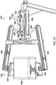
- Clamping device 1212 may be equipped with lever 1204 with handle 1206. While Figure 12 shows quantity two of rod assembly 1202 attached to lever 1204, in other embodiments, one rod assembly 1202 or more than two rod assemblies 1202 may be used.
- Sliding mechanism 1208 controls opening and closing of jaw component 1216 and jaw component 1218 of the clamping device 1212. Sliding mechanism 1208 is connected by rigid, pin-connected rod 1224 and rod 1226 to arm 1234 and arm 1236 that have jaw component 1216 and jaw component 1218.
- Figure 13 depicts a clamping device with lever 1304 in an up position 1348 that a user may activate.
- Figure 14 depicts an application for a rod assembly 1402 in accordance with an illustrative embodiment.
- Figure 14 depicts clamping device 1412 including quantity two of rod assembly 1402 attached.
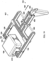
- Figure 14 depicts clamping device 1412 with lever 1404 and handle 1406 presently in an up or forward position.
- Lever 1404 and handle 1406 presently in the up or forward position indicates that jaw component 1416 and jaw component 1418 are presently exerting tension or in the process of releasing object 1438.
- Figure 14 also depicts sliding mechanism 1408, rod 1424, rod 1426, arm 1434, and arm 1436.
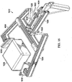
- Figure 15 shows clamping device 1512 in an open position 1550 wherein two rod assemblies 1502 are acting in compression 1552 to force jaw component 1516 and jaw component 1518 open 1550.
- Figure 16 depicts an application for a rod assembly 1602 in accordance with an illustrative embodiment.
- Figure 16 depicts clamping device 1612 including quantity two of rod assembly 1602 attached.
- Figure 16 depicts clamping device 1612 with lever 1604 and handle 1606 presently in a fully forward position.
- Lever 1604 and handle 1606 presently in a fully forward position indicates that jaw component 1616 and jaw component 1618 are presently exerting tension and have released object 1638.
- Figure 16 also depicts sliding mechanism 1608, rod 1624, rod 1626, arm 1634, and arm 1636.
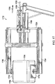
- Figure 17 and Figure 18 shows clamping device 1712 and 1812 in a closed position 1754 and 1854.
- Handle 1706 and 1806 are pulled back 1756 and 1856 and jaw components 1716 and 1718 begin to close around object 1738 and 1838 to be clamped 1758 and 1858.
- biasing device 1704 begins to be.extended.
- the illustrative embodiments provide for a known clamping force to be calculated based on the spring constant of biasing device 204 and based on the calibration level exhibited on tension rod 208.
- biasing device 204 may obey Hooke's law, which states that the force with which biasing device 204 pushes back is linearly proportional to the distance from its equilibrium length.
- F -kx, where x is the displacement vector, defined as the distance and direction biasing device 204 is deformed from its equilibrium length, F is the resulting force vector, defined as the magnitude and direction of the restoring force biasing device 204 exerts, and k is the spring constant of biasing device 204, a constant that depends on the material and construction of biasing device 204.
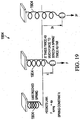
- Figure 19 is an illustration of Hooke's Law.
- Figure 19 depicts biasing device 1904, which in an embodiment is a spring with a spring constant k.
- displacement vector is represented as the variable x.
- Figure 19 illustrates that to stretch spring 1904 twice as far as a previous length may require twice the force exerted to achieve stretching to the previous length.
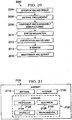
- Figure 20 is a flowchart of a method of manufacturing a commercial aircraft.
- exemplary method 2000 may include specification and design 2004 of the aircraft 2102 and material procurement 2006.
- component and subassembly manufacturing 2008 and system integration 2010 of the aircraft 2102 takes place.
- the aircraft 2102 may go through certification and delivery 2012 in order to be placed in service 2014.
- routine maintenance and service 2016 which may also include modification, reconfiguration, refurbishment, and so on).
- a system integrator may include without limitation, any number of aircraft manufacturers and major-system subcontractors
- a third party may include without limitation, any number of venders, subcontractors, and suppliers
- an operator may be an airline, leasing company, military entity, service organization, and so on.
- Figure 21 is a block diagram of a commercial aircraft.
- the aircraft 2102 produced by exemplary method 2000 may include an airframe 2118 with a plurality of systems 2120 and an interior 2122.
- high-level systems 2120 include one or more of a propulsion system 2124, an electrical system 2126, a hydraulic system 2128, and an environmental system 2130. Any number of other systems maybe included.
- an aerospace example is shown, the principles of the invention may be applied to other industries, such as the automotive industry.
- Apparatus and methods embodied herein may be employed during any one or more of the stages of the production and service method 2000.
- components or subassemblies corresponding to production process 2008 may be fabricated or manufactured in a manner similar to components or subassemblies produced while the aircraft 2102 is in service.
- one or more apparatus embodiments, method embodiments, or a combination thereof may be utilized during the production stages 2008 and 2010, for example, by substantially expediting assembly of or reducing the cost of an aircraft 2102.
- one or more of apparatus embodiments, method embodiments, or a combination thereof may be utilized while the aircraft 2102 is in service, for example and without limitation, to maintenance and service 2016.
Description
- The present disclosure relates generally to the controlling of an object through the use of adjustable compression and tension based on indications of compression and tension. In particular, the present invention relates to a system according to the preamble of claim 1 and a method of using the system of claim 1 for employing an object configured to apply a biasing force, the object being compressed and extended by rods whose position may be fixed, in conjunction with a device that may clamp and hold the captured object with a known pressure.
FR 2982516 A1 - Compression rods, tension rods, and extension rods are used for many purposes, including retaining and stabilizing an object. Currently known devices include shock absorbers, spring loaded clamping devices, and coupling nut devices. Shock absorbers control an amount of compression to known objects while reducing extension recovery time. Shock absorbers smooth out and damp shock impulse as well as dissipate kinetic energy. Spring loaded clamping devices support the holding of an object in place by exerting over forces or under forces or spring actuated forces.
- Coupling nut devices are used to create extended rod assemblies from shorter lengths of rods. Coupling nut devices may use a threaded fastener to join two male threads, commonly known as externally threaded rods. By drawing two threaded male rods closer together or driving them farther apart, an overall length of the combined two rods and coupling nut device may be fixed and known. More than one coupling nut device may be used with a plurality of threaded male rods, to create a rod assembly of more extended length.
- Tension rods have a variety of applications wherein ends of a rod are forced outward to press against fixed surfaces. Curtain rods containing springs that install into window frames or shower stalls without a need for fixed hanging hardware are examples of domestic uses of tension rods.
- Load cells and limit switches are used in applying compression and tension in industrial applications. Load cells are transducers that convert force into electrical signals. Limit switches are operated by the motion of a machine part or presence of an object. They are used for control of a machine, as safety interlocks, or to count objects passing a point. Standardized limit switches are industrial control components that may be operated by the motion of the operating lever. Gas cylinders, gas struts, and various hydraulic devices are also used in applications requiring compression and tension.
- While these devices provide examples of applications that apply compression and tension, none of these applications are able to steadily apply fixed and known compression or tension, particularly in connection with grasping and maintaining hold of an object that may be fragile, while rigidity of the device is concurrently maintained. Accordingly, there is a need for a method and apparatus which takes into account one or more of the issues discussed above as well as possibly other issues.
-
FR2982516 - The illustrative embodiments provide for a system comprising a rod assembly. The rod assembly comprises a biasing device that returns to a rest position when the biasing device is subjected to one of a first compression by a first object and a first tension by a second object in which the first tension causes a second compression of a third object, in which the first compression causes a second tension of the third object, in which elongation of the rod assembly simultaneously occurs with the first tension and the second compression, and in which elongation of the rod assembly simultaneously occurs with the second tension and the first compression. The illustrative embodiments also provide for an apparatus. The apparatus comprises an apparatus with adjustable compression, tension, and extension. The apparatus comprises a housing component comprising a hollow tube, a compression rod configured to insert partially inside a first end of the housing component, and a coupling nut attached to the compression rod, the coupling nut configured to affix a position of the compression rod relative to the housing component. The apparatus also comprises a tension rod configured for partial insertion inside a second end of the housing component and a biasing device configured for placement inside the housing component between and attached to the tension rod and the compression rod. Adjustments to positioning of at least one of the compression rod and the tension rod relative to the housing component alter compression and tension of the biasing device and cause the apparatus to respectively one of push and pull devices contacting the apparatus.
- The illustrative embodiments also provide for a method for controlling an amount of force required to retain and release at least one object through clamping and holding. The method comprises attaching a rod assembly to a clamping device, the clamping device comprising jaws for applying one of a first tension and a first compression to an object, the clamping device further comprising a handle in which pulling the handle causes the jaws to apply the first compression to the object, and in which pushing the handle causes the jaws to apply the first tension to the object. The method also comprises turning a coupling nut on a first shaft of the rod assembly to set a second tension of a biasing device in the rod assembly until the second tension is exhibited on markers displayed on a second shaft of the rod assembly, the second tension causing a second compression against the object when the handle is pulled. The method also comprises turning the first shaft in the rod assembly to set a third compression exerted by the rod assembly, the third compression exerted by the rod assembly causing a third tension against the object when the handle is pushed in which turning the coupling nut additionally adjusts length of the rod assembly simultaneous with setting the second tension and the second compression and simultaneous with setting the third compression and the third tension.
- The illustrative embodiments also provide for a method comprising simultaneously applying, using only a single rod assembly, compression, tension, and elongation of the single rod assembly to a tool connected to the single rod assembly.
- In summary, according to the invention there is provided a system comprising a rod assembly and a clamping device as claimed in claim 1.
- Optionally, a first adjustment to a first position of the first shaft in relation to the tubular housing component results in a compression of the third object and wherein a second adjustment to a second position of the second shaft in relation to the tubular housing component results in a third tension of the object.
- Optionally, the biasing device is an elastic device.
- Optionally, the biasing device is an elastomeric device.
- Optionally, the biasing device is a spring with a known elastic force property; and wherein the known elastic force property is a spring constant.
- The rod assembly is used in conjunction with a clamping device; and wherein the clamping device applies the second compression to the object and applies the second tension to the object.
- Optionally, the second shaft is calibrated to the spring constant; and wherein a level of tension exerted on the spring is determined from observing a length of the second shaft protruding outside the tubular housing component.
- According to another aspect of the invention there is provided a method of using the system of claim 1 for controlling an amount of force required to retain and release at least one object through clamping and holding as claimed in
claim 6. - Optionally, first shaft and the second shaft are placed at opposite ends of the biasing device. Optionally, the biasing device is a spring.
- Optionally, the markers displayed on the second shaft are calibrated to a spring constant of the biasing device.
- The features, functions, and benefits may be achieved independently in various embodiments of the present disclosure or may be combined in yet other embodiments in which further details can be seen with reference to the following description and drawings.
- The novel features believed characteristic of the illustrative embodiments are set forth in the appended claims. The illustrative embodiments, however, as well as a preferred mode of use, further objectives and features thereof, will best be understood by reference to the following detailed description of an illustrative embodiment of the present disclosure when read in conjunction with the accompanying drawings, wherein:
-
Figure 1 is a block diagram of a rod assembly in accordance with an illustrative embodiment; -
Figure 2 is a block diagram of a rod assembly and a clamping device in accordance with an illustrative embodiment. -
Figure 3 is a flowchart of a method for controlling an amount of force required to retain and release at least one object through clamping and holding in accordance with an illustrative embodiment; -
Figure 4 depicts a rod assembly in accordance with an illustrative embodiment; -
Figure 5 depicts an exploded rod assembly in accordance with an illustrative embodiment; -
Figure 6 depicts selected components of a rod assembly in accordance with an illustrative embodiment; -
Figure 7 depicts selected components of a rod assembly in accordance with an illustrative embodiment; -
Figure 8 depicts selected components of a rod assembly in accordance with an illustrative embodiment; -
Figure 9 depicts selected components of a rod assembly in accordance with an illustrative embodiment; -
Figure 10 depicts a rod assembly in accordance with an illustrative embodiment; -
Figure 11 depicts a rod assembly in accordance with an illustrative embodiment; -
Figure 12 depicts an application for a rod assembly in accordance with an illustrative embodiment; -
Figure 13 depicts an application for a rod assembly in accordance with an illustrative embodiment; -
Figure 14 depicts an application for a rod assembly in accordance with an illustrative embodiment; -
Figure 15 depicts an application for a rod assembly in accordance with an illustrative embodiment; -
Figure 16 depicts an application for a rod assembly in accordance with an illustrative embodiment; -
Figure 17 depicts an application for a rod assembly in accordance with an illustrative embodiment; and -
Figure 18 depicts an application for a rod assembly in accordance with an illustrative embodiment. -
Figure 19 is an illustration of Hooke's Law. -
Figure 20 is a flowchart of a method of manufacturing a commercial aircraft. -
Figure 21 is a block diagram of a commercial aircraft. - The illustrative embodiments recognize and take into account the issues described above, with respect to providing adjustable and fixable compression and tension for a rod assembly with adjustable length. Thus, the illustrative embodiments relate to systems and methods wherein one of tension and compression by the system provided herein may be affixed and held constant. The system provides methods for controlling an amount of force required to retain and release an object or objects through clamping and holding. Controlling such required amount of force may be accomplished through using an adjustable tension indication portion of the rod assembly.
- The illustrative embodiments also provide for controlling an amount of force required to retain or release an object or objects through a portion of the rod assembly that applies adjustable compression. The system also allows setting the desired extension of the rod assembly.
- The illustrative embodiments recognize that fragile objects may need to be grasped, clamped, lifted, and in some cases moved. Some objects may, for example, contain sensitive electronic parts. Effectively and safely grasping such objects may require applying an amount of grasping force that is adequate to take and maintain hold of such objects without risking dropping the objects, while at the same time not applying excessive grasping force that may damage the objects.
- The illustrative embodiments contemplate that the rod assembly of the present disclosure includes a tubular housing that contains a biasing device with an elastic property. In an embodiment, the biasing device may be a spring. The spring may be both compressible and stretchable. A first rod, or compression rod, that may be externally threaded, screws into a threaded end of the tubular housing and attach to one end of the spring.
- By adjusting an amount of the compression rod that is screwed into the tubular housing, and therefore pressing against the spring, a level of compression may be set. A second rod, or tension rod, that may not be threaded slides into an opposite or non-threaded end of the tubular housing and attach to the opposite end of the spring. The spring may have a known spring constant.
- The tension rod may be calibrated to the spring constant. When the tension rod, which is partially inside the tubular housing and attached to the spring, is pulled from the tubular housing, stripes or other indicia on the tension rod that are calibrated to the spring constant of the spring may be visible. These indicia may indicate the amount of tension or pulling force on the entire device.
- Screws or similar components may be placed in the tubular housing, a compression rod, the tension rod, or the coupling nut. These components may promote the device to remain rigid and maintain a desired level of compression or tension depending respectively on whether the spring has been pushed or pulled.
- The illustrative embodiments further provide for the threaded end of the tubular housing, the coupling nut, and the threaded compression rod to be used together to adjust the overall length of the rod assembly. Compression is controlled by back tension on the spring by the compression rod in the tubular housing. In other embodiments not falling under the scope of the claims tubular housing, the compression rod, and the coupling nut might not be threaded and instead may bind to each other using components and methods other than threading.
- The illustrative embodiments further contemplate that the rod assembly is used in conjunction with a clamping mechanism or device. Such a device clamps and maintains hold of the object of interest. The rod assembly is attached to the clamping device, such that the amount of tension or compression provided by the rod assembly directly bears upon an amount of pressure that the clamping device places against the object.
- Ends of the compression rod and the tension rod may be fitted into components of a clamping device associated with opening and closing the device on an object. Depending on a necessary level of pressure to be applied to the object, a compression or tension may be set for the rod assembly. The rod assembly then may attach to handles or other components of the clamping device that control closing and opening jaws that grasp and release the object.
- The illustrative embodiments further recognize that while the rod assembly of the present disclosure may be used in applications for applying pressure against an object that is being grasped and released, the rod assembly may be used in other applications. Such applications may call for the control of an amount of force wherein grasping or clamping is not involved.
- Attention is now turned to the figures.
Figure 1 is a block diagram of a rod assembly in accordance with an illustrative embodiment.System 100 includesrod assembly 102.Rod assembly 102 includes biasingdevice 104,first object 106, andsecond object 108.Biasing device 104 returns to a rest position when biasingdevice 104 is subjected to a first compression byfirst object 106.Biasing device 104 also returns to rest position when biasingdevice 104 is subjected to a first tension bysecond object 108. -
System 100 also includesthird object 110 that is not a component ofrod assembly 102.Third object 110 is subjected to forces created in part byrod assembly 102. - First tension causes a second compression of
third object 110. First compression causes a second tension ofthird object 110. Elongation ofrod assembly 102 simultaneously occurs with first tension and second compression. Elongation ofrod assembly 102 simultaneously occurs with second tension and first compression. -
Figure 2 is a block diagram ofsystem 200 of arod assembly 202 depicted in accordance with an illustrative embodiment.System 200 includes biasingdevice 204. In an embodiment, biasingdevice 204 may be a spring. While the term "biasingdevice 204" is used herein to indicate an object that both compresses and stretches, in other embodiments, biasingdevice 204 may not be a spring and may instead be another object with biasing force properties that urge biasingdevice 204 back to a rest position once biasingdevice 204 is one of stretched and compressed.Biasing device 204 may have components at each end permitting biasingdevice 204 to be grasped.Biasing device 204 may be composed of a metallic material, but may be another material such as a non-metallic material.Biasing device 204, if a spring, may have a known spring constant. -
System 200 also includescompression rod 206 andtension rod 208 that attach to biasingdevice 204 at opposite ends of biasingdevice 204.Compression rod 206 pushes upon or applies compression to biasingdevice 204.Tension rod 208 pulls or applies tension to biasingdevice 204. -
System 200 also includes clampingdevice 212 that usesrod assembly 202 to implement adjustments in applying pressure.System 200 also includesobject 210 which is grasped and released by clampingdevice 212. Amounts of compression and tension applied by clampingdevice 212 againstobject 210 are affected by adjustments to components ofrod assembly 202 whenrod assembly 202 is being used in conjunction with clampingdevice 212. In an embodiment,rod assembly 202 is attached to clampingdevice 212 and used by clampingdevice 212 to implement changes in pressure againstobject 210. -
Rod assembly 202 may be used in manners entirely unrelated to clamping and releasing an object.Rod assembly 202 may apply compression, tension, and elongation in applications and embodiments that do not involve clampingdevice 212,object 210, and the actions of applying and releasing pressure on an object. -
System 200 also includeshousing 214 that is a component ofrod assembly 202.Housing 214 is a hollow, tubular structure that is internally threaded at one or more ends. In an illustrative embodiment,housing 214 is made of a metallic material.Housing 214 may, in other embodiments, be made of non-metallic material, for example, a plastic or a composite material.System 200 also may includescrew 216 and screw 218 that screw intohousing 214 and affix components insidehousing 214 into place to maintain rigidity ofrod assembly 202. -
Compression rod 206 is externally threaded and screws partially into an internally threaded end ofhousing 214.Compression rod 206 attaches to biasingdevice 204 insidehousing 214.Compression rod 206 pushes or pulls biasingdevice 204 to respectively compress or stretch biasingdevice 204. While not depicted inFigure 2 ,compression rod 206 may include a mechanism for attaching to biasingdevice 204, thereby facilitating the pulling or pushing of biasingdevice 204. -
System 200 also may includecoupling nut 220 that may be internally threaded and may screw ontocompression rod 206. Couplingnut 220 may be used to assist in turningcompression rod 206, whilecompression rod 206 screws in or out ofhousing 214. Turningcompression rod 206 may result in compression or tension of biasingdevice 204. Movingcoupling nut 220 may also change the overall length ofrod assembly 202. In an embodiment,compression rod 206 may include two separate, externally threaded rods joined bycoupling nut 220, a configuration that may facilitate changing the overall length ofrod assembly 202. -
System 200 also may includepin 222 and pin 224 that insert intocoupling nut 220 in a perpendicular or other manner to affixcoupling nut 220 in place. When couplingnut 220 is turned to a point such that an overall length ofrod assembly 202 is set, and a desired level of back tension is set on biasingdevice 204, it may be desirable to affixcoupling nut 220 in place to maintain rigidity, length, and tension.Pin 222 and pin 224 may be inserted into holes in a side ofcoupling nut 220.Pin 222 and pin 224 may slide, screw, or otherwise pass through the holes untilpin 222 and pin 224 make firm contact withcompression rod 206 and effectively lockcoupling nut 220 tocompression rod 206 and thus preventcoupling nut 220 from turning. Actions ofpin 222 and pin 224 may prevent changes in the overall length ofrod assembly 202 as well as changes to a tension on biasingdevice 204. Whilepin 222 and pin 224 are provided herein, in other embodiments,system 200 may be only one pin or may comprise three or more pins. Other types of stops might be used. In an embodiment, a second coupling nut may screw ontocompression rod 206 againstcoupling nut 220 to tighten againstcoupling nut 220. -
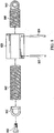
Tension rod 208 slides partially insidehousing 214 and attaches to end 226 of biasingdevice 204 that isopposite end 228 of biasingdevice 204 attached tocompression rod 206.Tension rod 208 slides intoend 230 ofhousing 214 that is not internally threaded. In an embodiment,tension rod 208 is calibrated withvisible band 232,band 234, andband 236 that may vary in color or other manner of indication between levels of calibration.Band 232,band 234, andband 236 may be calibrated to a spring constant of biasingdevice 204. - As
tension rod 208 pulls fromhousing 214, thus stretchingbiasing device 204,band 232,band 234, andband 236 may visibly indicate an increasing amount of tension on biasingdevice 204. In an illustrative example usingFigure 2 , astension rod 208 is pulled out fromhousing 214 thus applying tension to or stretchingbiasing device 204,band 232,band 234, andband 236 may appear in successive order. Appearance of each ofband 232,band 234, andband 236 astension rod 208 pulls out increasingly far may indicate an increasing level of tension on biasingdevice 204. Given a known spring constant for biasingdevice 204, appearance ofband 232 astension rod 208 is pulled may indicate a first level of tension on biasingdevice 204. Appearance ofband 232 andband 234 astension rod 208 is pulled out further may indicate a second level of tension on biasingdevice 204. Appearance ofband 232,band 234, andband 236 astension rod 208 is pulled out even further may indicate yet a third level of tension on biasingdevice 204. - The second level of tension is higher than first level of tension. The third level of tension is higher than second level of tension and first level of tension. In the
event tension rod 208 is pulled sufficiently far such that all ofband 232,band 234, andband 236 are visible, biasingdevice 204 may be stretched so far that elasticity of biasingdevice 204 is destroyed. In an event that biasingdevice 204 may be stretched so far that elasticity of biasingdevice 204 is nearing a point of destruction, color or other indicia of tension visible ontension rod 208 may indicate an alerted situation. -
Biasing device 204 is depicted inFigure 2 using a dotted line to indicate that biasingdevice 204 is insidehousing 214. Portions ofcompression rod 206 andtension rod 208 that are insidehousing 214 are also depicted using dotted lines. -
Figure 3 is a flowchart of a method for controlling an amount of force required to retain and release at least one object through clamping and holding in accordance with an illustrative embodiment.Method 300 shown inFigure 3 may be implemented usingsystem 100 ofFigure 1 andsystem 200 ofFigure 2 . The process depicted inFigure 3 may be a variation of the processes discussed in connection withFigure 1 , withFigure 2 and withFigure 4 through Figure 22 . Although the operations presented inFigure 3 are described as being performed by "a process," the operations may be performed using one or more physical devices, as described elsewhere herein. In an illustrative embodiment, the "process" may be one or more human users. -
Method 300 may begin as the process attachesrod assembly 202 to clampingdevice 212, clampingdevice 212 including jaws for applying one of a first compression and a first tension to object 210, clampingdevice 212 further including a handle in which pulling handle causes jaws to apply the first compression to object 210, and in which pushing handle causes jaws to apply the first tension to object 210 (operation 302). Jaws and handle of clampingdevice 212 are described in detail herein in discussion ofFigure 12 through Figure 18 . - The process may then turn
coupling nut 220 on a first shaft that may becompression rod 206 ofrod assembly 202 to set a second tension of biasingdevice 204 inrod assembly 202 until second tension is exhibited on markers that may beband 232,band 234, andband 236 displayed on a second shaft that may betension rod 208, second tension causing a second compression againstobject 210 when handle is pulled (operation 304). - The process may then turn the first shaft in
rod assembly 202 to set a third compression exerted byrod assembly 202, third compression exerted byrod assembly 202 causing a third tension againstobject 210 when handle is pushed in which turningcoupling nut 220 additionally adjusts length ofrod assembly 202 simultaneous with setting second tension and second compression and simultaneous with setting third compression and third tension (operation 306). -
Tension rod 208 hasend 238 andcompression rod 206 hasend 240 that are not insidehousing 214 and are at far ends ofrod assembly 202. Each ofend 238 and end 240 may have tabs with holes or other openings that permit attachment ofrod assembly 202 to other devices, including clampingdevice 212. - The process shown in
Figure 3 is exemplary only. The process may be varied, both in terms of the number of operations as well as in terms of what devices are used to carry out the operations. For example,different biasing devices 204 may be used in combination withdifferent tension rods 208 depending on levels of tension desired and overall demands of a task. In addition, as noted above,compression rod 206 may comprise two separate components that are joined bycoupling nut 220, an arrangement that may support greater flexibility in extending overall length of rod assembly. -
Figure 4 depictsrod assembly 402 in accordance with an illustrative embodiment. Components shown inFigure 4 through Figure 11 are indexed to components inFigure 1 and Figure 2 .Rod assembly 402 shown inFigure 4 corresponds torod assembly 102 sown inFigure 1 androd assembly 202 shown inFigure 2 .Compression rod 406 shown inFigure 4 corresponds tofirst object 106 shown inFigure 1 andcompression rod 206 shown inFigure 2 .Tension rod 408 shown inFigure 4 corresponds tosecond object 108 shown inFigure 1 andtension rod 208 shown inFigure 2 .Housing 414 shown inFigure 4 corresponds to housing 214 shown inFigure 2 .Screw 416 and screw 418 shown inFigure 4 correspond to screw 216 and screw 218, respectively, shown inFigure 2 . Couplingnut 420 shown inFigure 4 corresponds tocoupling nut 220 shown inFigure 2 .Pin 422 and pin 424 shown inFigure 4 correspond to pin 222 andpin 224, respectively, shown inFigure 2 .End 438 and end 440 shown inFigure 4 correspond to end 238 and end 240, respectively, shown inFigure 2 . -
Rod assembly 402 inFigure 4 is depicted withcompression rod 406 andtension rod 408 placed relatively far insidehousing 414 ofFigure 4 .End 438 is part oftension rod 408 and may attach to clampingdevice 212 shown inFigure 2 .End 440 is part ofcompression rod 406 and may also attach to clampingdevice 212 shown inFigure 2 . In an embodiment, end 438 and end 440 may be clevis fasteners. -
Figure 5 depicts an exploded rod assembly in accordance with an illustrative embodiment, with an exploded view of components of the rod assembly. As with components ofFigure 4 , components ofFigure 5 are indexed to components ofFigure 1 and Figure 2 . -
Rod assembly 502 shown inFigure 5 corresponds torod assembly 102 shown inFigure 1 androd assembly 202 shown inFigure 2 .Biasing device 504 shown inFigure 5 corresponds to biasingdevice 104 shown inFigure 1 and biasingdevice 204 shown inFigure 2 .Compression rod 506 shown inFigure 5 corresponds tofirst object 106 shown inFigure 1 andcompression rod 206 shown inFigure 2 .Tension rod 508 shown inFigure 5 corresponds tosecond object 108 shown inFigure 1 andtension rod 208 shown inFigure 2 .Housing 514 shown inFigure 5 corresponds to housing 214 shown inFigure 2 .Screw 516 and screw 518 shown inFigure 5 correspond to screw 216 and screw 218, respectively, shown inFigure 2 . Couplingnut 520 shown inFigure 5 corresponds tocoupling nut 220 shown inFigure 2 . Band 532, band 534, andband 536 shown inFigure 5 correspond to band 232,band 234, andband 236, respectively, shown inFigure 2 .End 538 and end 540 shown inFigure 5 correspond to end 238 and end 240, respectively, shown inFigure 2 . -
Figure 5 depictsswivel hook 550 attached to end ofcompression rod 506.Swivel hook 550 attaches to biasingdevice 504 and swivels so as not to twist biasingdevice 504 during turning ofcompression rod 506.Figure 5 also showseyelet 544, which attaches totension rod 508 and attaches to biasingdevice 504. While discussion herein ofFigure 5 enumerates band 532, band 534, andband 536,Figure 5 provides a depiction of more than three bands for illustration and discussion purposes. The provision of three bands inFigure 2 was purely for discussion purposes. In an embodiment,rod assembly 202 may have no bands or one or two bands. In an embodiment,rod assembly 202 may have more than three bands. -
Figure 5 also depicts three semicircles surrounding components ofFigure 5 . The semicircles, referred to hereinafter as views, surround components ofFigure 5 to be discussed in association with subsequent figures. A first semicircle denoted asView 5 encompassestension rod 508 and associated components. A second semicircle denoted asView 6, encompasseshousing 514 and associated components. A third semicircle denoted asView 7, encompassescompression rod 506 and associated components. -
Figure 6 depicts selected components of a rod assembly in accordance with an illustrative embodiment.Figure 6 depicts contents ofView 5 fromFigure 5 which includetension rod 608,end 638, band 632, band 634, band 636 andeyelet 644.Tension rod 608,end 638, band 632, band 634, band 636 andeyelet 644 correspond totension rod 508,end 538, band 532, band 534,band 536 andeyelet 544, respectively, depicted inFigure 5 . -
Figure 7 depicts selected components of a rod assembly in accordance with an illustrative embodiment.Figure 7 depicts contents ofView 6 fromFigure 5 includinghousing 714,screw 716, and screw 718.Housing 714,screw 716, and screw 718 correspond tohousing 514,screw 516, and screw 518, respectively, depicted inFigure 5 . -
Figure 8 depicts selected components of a rod assembly in accordance with an illustrative embodiment.Figure 8 depicts contents ofView 7 fromFigure 5 includingcompression rod 806,pin 822,pin 824,end 840,swivel hook 850, andbolt 852.Compression rod 806,end 840,swivel hook 850, and bolt 852 corresponds tocompression rod 506,end 540,swivel hook 550, and bolt 552, respectively, depicted inFigure 5 .Bolt 852 screws into and affixesswivel hook 850 to end ofcompression rod 806 that screws into threaded end ofhousing 514 ofFigure 5 . As discussed previously,compression rod 806 may be provided as more than one physical component, as shown inFigure 8 .Secondary compression rod 842 may be a second compression rod when compression rod is more than one physical component. -
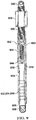
Figure 9 depicts selected components of a rod assembly in accordance with an illustrative embodiment. InFigure 9 , the interior ofhousing 914 is made visible.Biasing device 904,compression rod 906,tension rod 908,housing 914,screw 916, and screw 918 shown inFigure 9 correspond to biasingdevice 504,compression rod 506,tension rod 508,housing 514,screw 516, and screw 518 shown inFigure 5 . Couplingnut 920, band 932, band 934, band 936,end 938, and end 940 shown inFigure 9 correspond tocoupling nut 520, band 532, band 534,band 536,end 538, and end 540 shown inFigure 5 .Biasing device 904, band 932, band 934, band 936,eyelet 944,swivel hook 950, and bolt 952 are depicted although they are insidehousing 914. These components would not be visible unlesshousing 914 was made from a transparent or translucent material. -
Figure 10 depictsrod assembly 1002 in accordance with an illustrative embodiment.Biasing device 1004,compression rod 1006,tension rod 1008,housing 1014,screw 1016, andscrew 1018 shown inFigure 10 correspond to biasingdevice 504,compression rod 506,tension rod 508,housing 514,screw 516, and screw 518 shown inFigure 5 .Coupling nut 1020, band 1032, band 1034, band 1036, and end 1038 shown inFigure 10 correspond tocoupling nut 520, band 532, band 534,band 536, and end 538 shown inFigure 5 - In
Figure 10 ,tension rod 1008, instead of having a tabbed external end as discussed to this point, has a threaded external end. The illustrative embodiments provide for multiple coupling nuts to be deployed. In the embodiment shown inFigure 10 ,second coupling nut 1046 screws onto the threaded end oftension rod 1008. Screwingsecond coupling nut 1046 onto threaded end oftension rod 1008 may permitextension rod 1048 to be screwed intosecond coupling nut 1046, thus extending overall length ofrod assembly 1002. Screwingsecond coupling nut 1046 onto threaded end oftension rod 1008 may affect use in a device as it allows a different type of coupling. -
Figure 11 depicts arod assembly 1102 in accordance with an illustrative embodiment that is similar to the embodiment depicted inFigure 10 .Biasing device 1104,compression rod 1106,tension rod 1108,housing 1114,screw 1116, andscrew 1118 shown inFigure 11 correspond to biasingdevice 504,compression rod 506,tension rod 508,housing 514,screw 516, and screw 518 shown inFigure 5 .Coupling nut 1120, band 1132, band 1134, band 1136, and end 1138 shown inFigure 11 correspond tocoupling nut 520, band 532, band 534,band 536, and end 538 shown inFigure 5 -
Tension rod 1108 inFigure 11 is depicted with a threaded end. However, a coupling nut similar tocoupling nut 1046 inFigure 10 is not present ontension rod 1108 as inFigure 10 . Rather,coupling nut 1120 is depicted oncompression rod 1106 as provided for in previous illustrative embodiments. -
Figure 12 through Figure 18 depict applications for arod assembly Figure 12 through Figure 18 depictclamping device rod assembly Figure 12 through Figure 18 shows clamping device boxlike object object third object 110 shown inFigure 1 and object 210 shown inFigure 2 . In an embodiment,object -
Clamping device Figure 12 through Figure 18 may be identical for discussion purposes herein. References herein to components ofclamping device 1212 apply to components of clampingdevices clamping device 1212 and its components may be assumed to apply to each of clampingdevices -
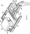
Clamping device 1212 may be equipped withlever 1204 withhandle 1206. WhileFigure 12 shows quantity two of rod assembly 1202 attached tolever 1204, in other embodiments, one rod assembly 1202 or more than two rod assemblies 1202 may be used. Slidingmechanism 1208 controls opening and closing ofjaw component 1216 andjaw component 1218 of theclamping device 1212. Slidingmechanism 1208 is connected by rigid, pin-connectedrod 1224 androd 1226 toarm 1234 andarm 1236 that havejaw component 1216 andjaw component 1218. - When
lever 1204 is pushed forward 1240, rod assembly 1202 is compressed andjaw component 1216 andjaw component 1218 of the clamping device are opened 1242. Whenlever 1204 is pulled back 1244 or away from object 1202 being clamped, slidingmechanism 1208 is also pulled back 1246. Pullinglever 1204 action forcesjaw component 1216 andjaw component 1218 to clampobject 1238. Tension set for rod assembly 1202 affects pressure onobject 1238 by clampingdevice 1212. A relationship between tension set for rod assembly 1202 and pressure onobject 1238 by clampingdevice 1212 may be illustrated through a discussion of Hooke's Law, F =-kx, where F is a force vector, k is a constant, and x is the displacement vector. Given a spring constant for biasingdevice 204 and appropriately calibratedtension rod 208, a known clamping force may be determined from indicated level of tension shown ontension rod 208 inFigure 2 . -
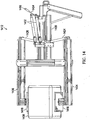
Figure 13 depicts a clamping device withlever 1304 in an upposition 1348 that a user may activate.Figure 14 depicts an application for arod assembly 1402 in accordance with an illustrative embodiment.Figure 14 depicts clampingdevice 1412 including quantity two ofrod assembly 1402 attached.Figure 14 depicts clampingdevice 1412 withlever 1404 and handle 1406 presently in an up or forward position.Lever 1404 and handle 1406 presently in the up or forward position indicates thatjaw component 1416 andjaw component 1418 are presently exerting tension or in the process of releasingobject 1438.Figure 14 also depicts slidingmechanism 1408,rod 1424,rod 1426,arm 1434, andarm 1436. -
Figure 15 shows clamping device 1512 in anopen position 1550 wherein tworod assemblies 1502 are acting incompression 1552 to forcejaw component 1516 andjaw component 1518 open 1550.Figure 16 depicts an application for arod assembly 1602 in accordance with an illustrative embodiment.Figure 16 depicts clampingdevice 1612 including quantity two ofrod assembly 1602 attached.Figure 16 depicts clampingdevice 1612 withlever 1604 and handle 1606 presently in a fully forward position.Lever 1604 and handle 1606 presently in a fully forward position indicates thatjaw component 1616 andjaw component 1618 are presently exerting tension and have releasedobject 1638.Figure 16 also depicts slidingmechanism 1608,rod 1624,rod 1626,arm 1634, andarm 1636. -
Figure 17 andFigure 18 shows clamping device closed position 1754 and 1854.Handle jaw components object jaw component 1716 andjaw component 1718touch object 1738 on either side ofobject 1738 or however clamping is effected,biasing device 1704 begins to be.extended. - The illustrative embodiments provide for a known clamping force to be calculated based on the spring constant of biasing
device 204 and based on the calibration level exhibited ontension rod 208. The illustrative embodiments recognize that biasingdevice 204 may obey Hooke's law, which states that the force with whichbiasing device 204 pushes back is linearly proportional to the distance from its equilibrium length. A formula that may apply is F = -kx, where x is the displacement vector, defined as the distance anddirection biasing device 204 is deformed from its equilibrium length, F is the resulting force vector, defined as the magnitude and direction of the restoringforce biasing device 204 exerts, and k is the spring constant of biasingdevice 204, a constant that depends on the material and construction of biasingdevice 204. -
Figure 19 is an illustration of Hooke's Law.Figure 19 depicts biasingdevice 1904, which in an embodiment is a spring with a spring constant k. InFigure 19 , displacement vector is represented as the variable x.Figure 19 illustrates that tostretch spring 1904 twice as far as a previous length may require twice the force exerted to achieve stretching to the previous length. - The illustrative embodiments contemplate that the formula described in the preceding paragraph or other formulae or methods may be used to calculate tension applied by a rod assembly in various applications. While the discussion herein has concerned the use of a
rod assembly 202 with aclamping device 212, other applications for arod assembly 202 not limited to clamping or grasping are provided for by the systems and methods taught herein. -
Figure 20 is a flowchart of a method of manufacturing a commercial aircraft. Referring toFigure 20 and Figure 21 , embodiments of the disclosure may be described in the context of an aircraft manufacturing andservice method 2000 as shown inFigure 20 and anaircraft 2102 as shown inFigure 21 . During pre-production,exemplary method 2000 may include specification anddesign 2004 of theaircraft 2102 andmaterial procurement 2006. During production, component andsubassembly manufacturing 2008 andsystem integration 2010 of theaircraft 2102 takes place. Thereafter, theaircraft 2102 may go through certification anddelivery 2012 in order to be placed inservice 2014. While in service by a customer, theaircraft 2102 is scheduled for routine maintenance and service 2016 (which may also include modification, reconfiguration, refurbishment, and so on). - Each of the processes of
method 2000 may be performed or carried out by a system integrator, a third party, and/or an operator (e.g., a customer). For the purposes of this description, a system integrator may include without limitation, any number of aircraft manufacturers and major-system subcontractors; a third party may include without limitation, any number of venders, subcontractors, and suppliers; and an operator may be an airline, leasing company, military entity, service organization, and so on. -
Figure 21 is a block diagram of a commercial aircraft. As shown inFigure 21 , theaircraft 2102 produced byexemplary method 2000 may include anairframe 2118 with a plurality ofsystems 2120 and an interior 2122. Examples of high-level systems 2120 include one or more of apropulsion system 2124, anelectrical system 2126, ahydraulic system 2128, and anenvironmental system 2130. Any number of other systems maybe included. Although an aerospace example is shown, the principles of the invention may be applied to other industries, such as the automotive industry. - Apparatus and methods embodied herein may be employed during any one or more of the stages of the production and
service method 2000. For example, components or subassemblies corresponding toproduction process 2008 may be fabricated or manufactured in a manner similar to components or subassemblies produced while theaircraft 2102 is in service. Also, one or more apparatus embodiments, method embodiments, or a combination thereof may be utilized during theproduction stages aircraft 2102. Similarly, one or more of apparatus embodiments, method embodiments, or a combination thereof may be utilized while theaircraft 2102 is in service, for example and without limitation, to maintenance andservice 2016. - The description of the different illustrative embodiments has been presented for purposes of illustration and description, and is not intended to be exhaustive or limited to the embodiments in the form disclosed. Many modifications and variations will be apparent to those of ordinary skill in the art. Further, different illustrative embodiments may provide different features as compared to other illustrative embodiments. The embodiment or embodiments selected are chosen and described in order to best explain the invention, the practical application, and to enable others of ordinary skill in the art to understand the disclosure for various embodiments with various modifications as are suited to the particular use contemplated.
Claims (10)
- A system (100) comprising a rod assembly (202) and a clamping device (1212), wherein the rod assembly (202) is attached to the clamping device (1212) and the rod assembly (202) comprising a first shaft (206), a second shaft (208) and a biasing device (204), wherein said biasing device (204) is configured to return to a rest position when the biasing device (204) is subjected to a first compression by said first shaft (206); characterized in that
said rod assembly (202) configured to provide: a first tension by said second shaft (208) in which the first tension causes a second compression of an object (1238) by the clamping device (1212),
in which the first compression causes a second tension of the object (1238) by the clamping device (1212), in which elongation of the rod assembly (202) simultaneously occurs with the first tension and the second compression, in which elongation of the rod assembly (202) simultaneously occurs with the second tension and the first compression;
wherein the first shaft (206) is partially disposed within a tubular housing component (214) and the first shaft (206) being attached to a first end of the biasing device (204); and
wherein the second shaft (208) is partially disposed within the tubular housing component (214) and the second shaft (208) being attached to a second end of the biasing device (204); wherein the biasing device (204) is placed inside the tubular housing component and
wherein the tubular housing component (214) is internally threaded on one end, wherein the first shaft (206) is externally threaded, and wherein the first shaft (206) is screwable into the tubular housing component (214) at the end of the tubular housing component (214) that is internally threaded. - The system of claim 1, wherein the rod assembly (202) is configured with a first adjustment to a first position of the first shaft (206) in relation to the tubular housing component (214) resulting in a third compression of the object (1238) and with a second adjustment to a second position of the second shaft (208) in relation to the tubular housing component (214) resulting in a third tension of the object (1238).
- The system of any one of the preceding claims, wherein the biasing device (204) is an elastic device.
- The system of any one of the preceding claims, wherein the biasing device (204) is an elastomeric device.
- The system of any one of the preceding claims, wherein the biasing device (204) is a spring with a known elastic force property; and
wherein the known elastic force property is a spring constant. - A method of using the system (200) of claim 1 for controlling an amount of force required to retain and release at least one object (1238) through clamping and holding, comprising:wherein the clamping device (1212) comprises jaws for applying one of a first tension and a first compression to an object (1238) which is able to be grasped and released by the clamping device, the clamping device (1212) further comprising a handle (1206) in which pulling the handle (1206) causes the jaws to apply the first compression to the object and in which pushing the handle (1206) causes the jaws to apply the first tension to the object (1238);turning a coupling nut (220) on said first shaft (206) of the rod assembly (202) to set a second tension of said biasing device (204) in the rod assembly (202) until the second tension is exhibited on markers (232, 234, 236) displayed on a second shaft (208) of the rod assembly (202), the second tension causing a second compression against the object (1238) when the handle (1206) is pulled; andturning the first shaft (206) in the rod assembly (202) to set a third compression exerted by the rod assembly (202), the third compression exerted by the rod assembly (202) causing a third tension against the object (1238) when the handle (1206) is pushed in which turning the coupling nut (220) additionally adjusts length of the rod assembly (202) simultaneous with setting the second tension and the second compression and simultaneous with setting the third compression and the third tension.
- The method of claim 6, wherein the first shaft (206) and the second shaft (208) are placed at opposite ends of the biasing device (204).
- The method of claim 6 or 7, wherein the biasing device (204) is a spring.
- The method of any one of claims 6 to 8, wherein the markers (232, 234, 236) displayed on the second shaft (208) are calibrated to a spring constant of the biasing device (204).
- The method of claim 9, wherein a level of tension exerted on the spring is determined from observing a length of the second shaft (208) protruding outside the tubular housing component (214).
Applications Claiming Priority (1)
| Application Number | Priority Date | Filing Date | Title |
|---|---|---|---|
| US13/899,005 US9618069B2 (en) | 2013-05-21 | 2013-05-21 | Adjustable compression, adjustable tension rod indicator, and adjustable extension rod |
Publications (3)
| Publication Number | Publication Date |
|---|---|
| EP2805798A2 EP2805798A2 (en) | 2014-11-26 |
| EP2805798A3 EP2805798A3 (en) | 2015-08-19 |
| EP2805798B1 true EP2805798B1 (en) | 2016-12-21 |
Family
ID=50687295
Family Applications (1)
| Application Number | Title | Priority Date | Filing Date |
|---|---|---|---|
| EP14167560.3A Active EP2805798B1 (en) | 2013-05-21 | 2014-05-08 | System with adjustable compression, adjustable tension rod indicator, and adjustable extension rod |
Country Status (5)
| Country | Link |
|---|---|
| US (1) | US9618069B2 (en) |
| EP (1) | EP2805798B1 (en) |
| JP (1) | JP6389058B2 (en) |
| CN (1) | CN104179764B (en) |
| ES (1) | ES2620484T3 (en) |
Families Citing this family (43)
| Publication number | Priority date | Publication date | Assignee | Title |
|---|---|---|---|---|
| US9352411B2 (en) | 2008-05-28 | 2016-05-31 | Illinois Tool Works Inc. | Welding training system |
| US9101994B2 (en) | 2011-08-10 | 2015-08-11 | Illinois Tool Works Inc. | System and device for welding training |
| US9583014B2 (en) | 2012-11-09 | 2017-02-28 | Illinois Tool Works Inc. | System and device for welding training |
| US9368045B2 (en) | 2012-11-09 | 2016-06-14 | Illinois Tool Works Inc. | System and device for welding training |
| US9672757B2 (en) | 2013-03-15 | 2017-06-06 | Illinois Tool Works Inc. | Multi-mode software and method for a welding training system |
| US9666100B2 (en) | 2013-03-15 | 2017-05-30 | Illinois Tool Works Inc. | Calibration devices for a welding training system |
| US9713852B2 (en) | 2013-03-15 | 2017-07-25 | Illinois Tool Works Inc. | Welding training systems and devices |
| US9583023B2 (en) | 2013-03-15 | 2017-02-28 | Illinois Tool Works Inc. | Welding torch for a welding training system |
| US9728103B2 (en) | 2013-03-15 | 2017-08-08 | Illinois Tool Works Inc. | Data storage and analysis for a welding training system |
| US10056010B2 (en) | 2013-12-03 | 2018-08-21 | Illinois Tool Works Inc. | Systems and methods for a weld training system |
| US9757819B2 (en) * | 2014-01-07 | 2017-09-12 | Illinois Tool Works Inc. | Calibration tool and method for a welding system |
| US10170019B2 (en) | 2014-01-07 | 2019-01-01 | Illinois Tool Works Inc. | Feedback from a welding torch of a welding system |
| US10105782B2 (en) | 2014-01-07 | 2018-10-23 | Illinois Tool Works Inc. | Feedback from a welding torch of a welding system |
| US9589481B2 (en) | 2014-01-07 | 2017-03-07 | Illinois Tool Works Inc. | Welding software for detection and control of devices and for analysis of data |
| US9724788B2 (en) | 2014-01-07 | 2017-08-08 | Illinois Tool Works Inc. | Electrical assemblies for a welding system |
| US9751149B2 (en) | 2014-01-07 | 2017-09-05 | Illinois Tool Works Inc. | Welding stand for a welding system |
| US9937578B2 (en) | 2014-06-27 | 2018-04-10 | Illinois Tool Works Inc. | System and method for remote welding training |
| US10665128B2 (en) | 2014-06-27 | 2020-05-26 | Illinois Tool Works Inc. | System and method of monitoring welding information |
| US9862049B2 (en) | 2014-06-27 | 2018-01-09 | Illinois Tool Works Inc. | System and method of welding system operator identification |
| US10307853B2 (en) | 2014-06-27 | 2019-06-04 | Illinois Tool Works Inc. | System and method for managing welding data |
| US9724787B2 (en) | 2014-08-07 | 2017-08-08 | Illinois Tool Works Inc. | System and method of monitoring a welding environment |
| US11014183B2 (en) | 2014-08-07 | 2021-05-25 | Illinois Tool Works Inc. | System and method of marking a welding workpiece |
| US9875665B2 (en) | 2014-08-18 | 2018-01-23 | Illinois Tool Works Inc. | Weld training system and method |
| US11247289B2 (en) | 2014-10-16 | 2022-02-15 | Illinois Tool Works Inc. | Remote power supply parameter adjustment |
| US10239147B2 (en) | 2014-10-16 | 2019-03-26 | Illinois Tool Works Inc. | Sensor-based power controls for a welding system |
| US10210773B2 (en) | 2014-11-05 | 2019-02-19 | Illinois Tool Works Inc. | System and method for welding torch display |
| US10402959B2 (en) | 2014-11-05 | 2019-09-03 | Illinois Tool Works Inc. | System and method of active torch marker control |
| US10204406B2 (en) | 2014-11-05 | 2019-02-12 | Illinois Tool Works Inc. | System and method of controlling welding system camera exposure and marker illumination |
| US10417934B2 (en) | 2014-11-05 | 2019-09-17 | Illinois Tool Works Inc. | System and method of reviewing weld data |
| US10490098B2 (en) | 2014-11-05 | 2019-11-26 | Illinois Tool Works Inc. | System and method of recording multi-run data |
| US10373304B2 (en) | 2014-11-05 | 2019-08-06 | Illinois Tool Works Inc. | System and method of arranging welding device markers |
| US10427239B2 (en) | 2015-04-02 | 2019-10-01 | Illinois Tool Works Inc. | Systems and methods for tracking weld training arc parameters |
| US9759617B2 (en) * | 2015-04-10 | 2017-09-12 | The Boeing Company | Tool with over pressure indicator and lockout |
| US10438505B2 (en) | 2015-08-12 | 2019-10-08 | Illinois Tool Works | Welding training system interface |
| US10373517B2 (en) | 2015-08-12 | 2019-08-06 | Illinois Tool Works Inc. | Simulation stick welding electrode holder systems and methods |
| US10593230B2 (en) | 2015-08-12 | 2020-03-17 | Illinois Tool Works Inc. | Stick welding electrode holder systems and methods |
| US10657839B2 (en) | 2015-08-12 | 2020-05-19 | Illinois Tool Works Inc. | Stick welding electrode holders with real-time feedback features |
| CH711440A1 (en) * | 2015-08-21 | 2017-02-28 | Marenco Swisshelicopter Ag | Loader hook construction for attachment to or in a cabin structure of a helicopter. |
| US11248973B2 (en) * | 2017-02-16 | 2022-02-15 | C. R. Bard, Inc. | Insertion and withdrawal force measurement system |
| GB2560931B (en) * | 2017-03-28 | 2023-01-11 | Equinor Energy As | Connector |
| US11288978B2 (en) | 2019-07-22 | 2022-03-29 | Illinois Tool Works Inc. | Gas tungsten arc welding training systems |
| US11776423B2 (en) | 2019-07-22 | 2023-10-03 | Illinois Tool Works Inc. | Connection boxes for gas tungsten arc welding training systems |
| EP3842183A1 (en) * | 2019-12-23 | 2021-06-30 | WISTRA GmbH Cargo Control | Clamping device |
Family Cites Families (16)
| Publication number | Priority date | Publication date | Assignee | Title |
|---|---|---|---|---|
| US2586245A (en) | 1947-04-30 | 1952-02-19 | Donald K Mcrae | Combination gaff hook and scale |
| US2920665A (en) * | 1956-03-30 | 1960-01-12 | Clifford L Hutson | Clamping device with selectively yieldable or non-yieldable pressure means |
| EP0134819A1 (en) | 1978-08-01 | 1985-03-27 | Grisebach, Hans-Theodor | Gripping head with an electric clasping drive |
| GB2184060B (en) | 1985-12-02 | 1988-08-10 | British Gas Plc | Clamp for a component & a pipe to be joined |
| US4964479A (en) | 1989-10-10 | 1990-10-23 | Sumida Kunio A | Weight scale compensating for tare |
| US5358068A (en) | 1992-10-30 | 1994-10-25 | Whitmer Gerald T | Safety system including cable tensioner and shock absorber |
| US8292274B2 (en) | 2003-01-10 | 2012-10-23 | Barnes Group Inc. | Dampened compression spring rod |
| US7249907B2 (en) * | 2004-03-01 | 2007-07-31 | Kay Jon D | Spring loaded turnbuckle with quick disconnect |
| US7469617B2 (en) * | 2004-07-22 | 2008-12-30 | Honda Motor Co., Ltd. | Tension compensating assembly for mechanical control cables |
| US7219951B2 (en) * | 2005-04-04 | 2007-05-22 | Lippert Components | Tie-down assembly |
| US7331627B2 (en) | 2005-05-19 | 2008-02-19 | Joel Dean Van Den Brink | Lateral control rod for a cab suspension system |
| US7823466B2 (en) * | 2007-09-05 | 2010-11-02 | Glass David E | Device and method for adjusting, measuring, and setting force |
| EP2220393B1 (en) * | 2007-11-13 | 2019-07-24 | Campbell, Richard V. | Self-retracting extension limiting device |
| US8403115B2 (en) | 2008-01-11 | 2013-03-26 | Penske Racing Shocks | Dual rate gas spring shock absorber |
| CN101987435B (en) * | 2009-07-29 | 2014-02-19 | 鸿富锦精密工业(深圳)有限公司 | Clamp |
| FR2982516B1 (en) | 2011-11-16 | 2013-11-22 | Peugeot Citroen Automobiles Sa | TIGHTENING SYSTEM OF A SHEET FOR CHECKING THE CONFORMITY OF THE SHEET |
-
2013
- 2013-05-21 US US13/899,005 patent/US9618069B2/en active Active
-
2014
- 2014-04-28 JP JP2014093183A patent/JP6389058B2/en active Active
- 2014-05-08 EP EP14167560.3A patent/EP2805798B1/en active Active
- 2014-05-08 ES ES14167560.3T patent/ES2620484T3/en active Active
- 2014-05-12 CN CN201410198060.9A patent/CN104179764B/en active Active
Non-Patent Citations (1)
| Title |
|---|
| None * |
Also Published As
| Publication number | Publication date |
|---|---|
| JP2014228141A (en) | 2014-12-08 |
| JP6389058B2 (en) | 2018-09-12 |
| CN104179764B (en) | 2018-06-05 |
| US20140346793A1 (en) | 2014-11-27 |
| EP2805798A3 (en) | 2015-08-19 |
| ES2620484T3 (en) | 2017-06-28 |
| US9618069B2 (en) | 2017-04-11 |
| EP2805798A2 (en) | 2014-11-26 |
| CN104179764A (en) | 2014-12-03 |
Similar Documents
| Publication | Publication Date | Title |
|---|---|---|
| EP2805798B1 (en) | System with adjustable compression, adjustable tension rod indicator, and adjustable extension rod | |
| CN101583443B (en) | Riveting apparatus | |
| US20160109056A1 (en) | Readily stretchable/contractible and locatable cantilever support | |
| WO2020012481A3 (en) | Annuloplasty systems and locking tools therefor | |
| WO2007032007A3 (en) | Weight-measuring device | |
| US20170007425A1 (en) | Gripping device with switchable prehension modes | |
| WO2006014784A1 (en) | Retractable fastener device and method for facilitating the fastening of multiple objects | |
| US20140222199A1 (en) | Grasp assist device with shared tendon actuator assembly | |
| Wang et al. | Bio-inspired soft bistable actuator with dual actuations | |
| TWI703597B (en) | Pressing assembly | |
| US9217214B2 (en) | Systems and methods of drawstring restringing and recovery | |
| TWI656922B (en) | Retention and release mechanism for a power tool | |
| Clark et al. | Stiffness-tuneable limb segment with flexible spine for malleable robots | |
| US9328750B2 (en) | Strap clamp | |
| Saha et al. | Design and implementation of a 4-bar linkage gripper | |
| Liao et al. | Variable stiffness actuators embedded with soft-bodied polycaprolactone and shape memory alloy wires | |
| US20140234053A1 (en) | Elastic fasteners | |
| US20060185478A1 (en) | Locking tweezers for securing nuts or head bolts | |
| US11131407B1 (en) | Preload apparatus | |
| US11752606B1 (en) | Grasping and positioning tool and methods of using it | |
| US9120206B1 (en) | Cam-activated bench vise | |
| Scaff et al. | Non-conducting manipulator for live-line maintenance: Use of pneumatic artificial muscles | |
| CN109590935B (en) | Belt type wrench with adjustable caliber | |
| CN217345130U (en) | Adjustable tightener | |
| US20070056407A1 (en) | Hose clamp removal and installation tool |
Legal Events
| Date | Code | Title | Description |
|---|---|---|---|
| PUAI | Public reference made under article 153(3) epc to a published international application that has entered the european phase |
Free format text: ORIGINAL CODE: 0009012 |
|
| 17P | Request for examination filed |
Effective date: 20140508 |
|
| AK | Designated contracting states |
Kind code of ref document: A2 Designated state(s): AL AT BE BG CH CY CZ DE DK EE ES FI FR GB GR HR HU IE IS IT LI LT LU LV MC MK MT NL NO PL PT RO RS SE SI SK SM TR |
|
| AX | Request for extension of the european patent |
Extension state: BA ME |
|
| PUAL | Search report despatched |
Free format text: ORIGINAL CODE: 0009013 |
|
| AK | Designated contracting states |
Kind code of ref document: A3 Designated state(s): AL AT BE BG CH CY CZ DE DK EE ES FI FR GB GR HR HU IE IS IT LI LT LU LV MC MK MT NL NO PL PT RO RS SE SI SK SM TR |
|
| AX | Request for extension of the european patent |
Extension state: BA ME |
|
| RIC1 | Information provided on ipc code assigned before grant |
Ipc: B25B 5/04 20060101ALI20150716BHEP Ipc: B25B 5/12 20060101ALI20150716BHEP Ipc: B25B 5/16 20060101AFI20150716BHEP |
|
| GRAP | Despatch of communication of intention to grant a patent |
Free format text: ORIGINAL CODE: EPIDOSNIGR1 |
|
| INTG | Intention to grant announced |
Effective date: 20160406 |
|
| GRAJ | Information related to disapproval of communication of intention to grant by the applicant or resumption of examination proceedings by the epo deleted |
Free format text: ORIGINAL CODE: EPIDOSDIGR1 |
|
| GRAP | Despatch of communication of intention to grant a patent |
Free format text: ORIGINAL CODE: EPIDOSNIGR1 |
|
| INTC | Intention to grant announced (deleted) | ||
| INTG | Intention to grant announced |
Effective date: 20160727 |
|
| GRAS | Grant fee paid |
Free format text: ORIGINAL CODE: EPIDOSNIGR3 |
|
| STAA | Information on the status of an ep patent application or granted ep patent |
Free format text: STATUS: GRANT OF PATENT IS INTENDED |
|
| GRAA | (expected) grant |
Free format text: ORIGINAL CODE: 0009210 |
|
| STAA | Information on the status of an ep patent application or granted ep patent |
Free format text: STATUS: THE PATENT HAS BEEN GRANTED |
|
| AK | Designated contracting states |
Kind code of ref document: B1 Designated state(s): AL AT BE BG CH CY CZ DE DK EE ES FI FR GB GR HR HU IE IS IT LI LT LU LV MC MK MT NL NO PL PT RO RS SE SI SK SM TR |
|
| REG | Reference to a national code |
Ref country code: GB Ref legal event code: FG4D |
|
| REG | Reference to a national code |
Ref country code: CH Ref legal event code: EP |
|
| REG | Reference to a national code |
Ref country code: IE Ref legal event code: FG4D |
|
| REG | Reference to a national code |
Ref country code: AT Ref legal event code: REF Ref document number: 855054 Country of ref document: AT Kind code of ref document: T Effective date: 20170115 |
|
| REG | Reference to a national code |
Ref country code: DE Ref legal event code: R096 Ref document number: 602014005584 Country of ref document: DE |
|
| PG25 | Lapsed in a contracting state [announced via postgrant information from national office to epo] |
Ref country code: LV Free format text: LAPSE BECAUSE OF FAILURE TO SUBMIT A TRANSLATION OF THE DESCRIPTION OR TO PAY THE FEE WITHIN THE PRESCRIBED TIME-LIMIT Effective date: 20161221 |
|
| REG | Reference to a national code |
Ref country code: LT Ref legal event code: MG4D |
|
| REG | Reference to a national code |
Ref country code: NL Ref legal event code: MP Effective date: 20161221 |
|
| PG25 | Lapsed in a contracting state [announced via postgrant information from national office to epo] |
Ref country code: NO Free format text: LAPSE BECAUSE OF FAILURE TO SUBMIT A TRANSLATION OF THE DESCRIPTION OR TO PAY THE FEE WITHIN THE PRESCRIBED TIME-LIMIT Effective date: 20170321 Ref country code: LT Free format text: LAPSE BECAUSE OF FAILURE TO SUBMIT A TRANSLATION OF THE DESCRIPTION OR TO PAY THE FEE WITHIN THE PRESCRIBED TIME-LIMIT Effective date: 20161221 Ref country code: GR Free format text: LAPSE BECAUSE OF FAILURE TO SUBMIT A TRANSLATION OF THE DESCRIPTION OR TO PAY THE FEE WITHIN THE PRESCRIBED TIME-LIMIT Effective date: 20170322 Ref country code: SE Free format text: LAPSE BECAUSE OF FAILURE TO SUBMIT A TRANSLATION OF THE DESCRIPTION OR TO PAY THE FEE WITHIN THE PRESCRIBED TIME-LIMIT Effective date: 20161221 |
|
| REG | Reference to a national code |
Ref country code: AT Ref legal event code: MK05 Ref document number: 855054 Country of ref document: AT Kind code of ref document: T Effective date: 20161221 |
|
| REG | Reference to a national code |
Ref country code: FR Ref legal event code: PLFP Year of fee payment: 4 |
|
| PG25 | Lapsed in a contracting state [announced via postgrant information from national office to epo] |
Ref country code: FI Free format text: LAPSE BECAUSE OF FAILURE TO SUBMIT A TRANSLATION OF THE DESCRIPTION OR TO PAY THE FEE WITHIN THE PRESCRIBED TIME-LIMIT Effective date: 20161221 Ref country code: RS Free format text: LAPSE BECAUSE OF FAILURE TO SUBMIT A TRANSLATION OF THE DESCRIPTION OR TO PAY THE FEE WITHIN THE PRESCRIBED TIME-LIMIT Effective date: 20161221 Ref country code: HR Free format text: LAPSE BECAUSE OF FAILURE TO SUBMIT A TRANSLATION OF THE DESCRIPTION OR TO PAY THE FEE WITHIN THE PRESCRIBED TIME-LIMIT Effective date: 20161221 |
|
| REG | Reference to a national code |
Ref country code: ES Ref legal event code: FG2A Ref document number: 2620484 Country of ref document: ES Kind code of ref document: T3 Effective date: 20170628 |
|
| PG25 | Lapsed in a contracting state [announced via postgrant information from national office to epo] |
Ref country code: NL Free format text: LAPSE BECAUSE OF FAILURE TO SUBMIT A TRANSLATION OF THE DESCRIPTION OR TO PAY THE FEE WITHIN THE PRESCRIBED TIME-LIMIT Effective date: 20161221 |
|
| PG25 | Lapsed in a contracting state [announced via postgrant information from national office to epo] |
Ref country code: RO Free format text: LAPSE BECAUSE OF FAILURE TO SUBMIT A TRANSLATION OF THE DESCRIPTION OR TO PAY THE FEE WITHIN THE PRESCRIBED TIME-LIMIT Effective date: 20161221 Ref country code: IS Free format text: LAPSE BECAUSE OF FAILURE TO SUBMIT A TRANSLATION OF THE DESCRIPTION OR TO PAY THE FEE WITHIN THE PRESCRIBED TIME-LIMIT Effective date: 20170421 Ref country code: CZ Free format text: LAPSE BECAUSE OF FAILURE TO SUBMIT A TRANSLATION OF THE DESCRIPTION OR TO PAY THE FEE WITHIN THE PRESCRIBED TIME-LIMIT Effective date: 20161221 Ref country code: SK Free format text: LAPSE BECAUSE OF FAILURE TO SUBMIT A TRANSLATION OF THE DESCRIPTION OR TO PAY THE FEE WITHIN THE PRESCRIBED TIME-LIMIT Effective date: 20161221 Ref country code: EE Free format text: LAPSE BECAUSE OF FAILURE TO SUBMIT A TRANSLATION OF THE DESCRIPTION OR TO PAY THE FEE WITHIN THE PRESCRIBED TIME-LIMIT Effective date: 20161221 |
|
| PG25 | Lapsed in a contracting state [announced via postgrant information from national office to epo] |
Ref country code: LU Free format text: LAPSE BECAUSE OF NON-PAYMENT OF DUE FEES Effective date: 20170531 Ref country code: BE Free format text: LAPSE BECAUSE OF FAILURE TO SUBMIT A TRANSLATION OF THE DESCRIPTION OR TO PAY THE FEE WITHIN THE PRESCRIBED TIME-LIMIT Effective date: 20161221 Ref country code: PT Free format text: LAPSE BECAUSE OF FAILURE TO SUBMIT A TRANSLATION OF THE DESCRIPTION OR TO PAY THE FEE WITHIN THE PRESCRIBED TIME-LIMIT Effective date: 20170421 Ref country code: BG Free format text: LAPSE BECAUSE OF FAILURE TO SUBMIT A TRANSLATION OF THE DESCRIPTION OR TO PAY THE FEE WITHIN THE PRESCRIBED TIME-LIMIT Effective date: 20170321 Ref country code: AT Free format text: LAPSE BECAUSE OF FAILURE TO SUBMIT A TRANSLATION OF THE DESCRIPTION OR TO PAY THE FEE WITHIN THE PRESCRIBED TIME-LIMIT Effective date: 20161221 Ref country code: SM Free format text: LAPSE BECAUSE OF FAILURE TO SUBMIT A TRANSLATION OF THE DESCRIPTION OR TO PAY THE FEE WITHIN THE PRESCRIBED TIME-LIMIT Effective date: 20161221 Ref country code: PL Free format text: LAPSE BECAUSE OF FAILURE TO SUBMIT A TRANSLATION OF THE DESCRIPTION OR TO PAY THE FEE WITHIN THE PRESCRIBED TIME-LIMIT Effective date: 20161221 |
|
| REG | Reference to a national code |
Ref country code: DE Ref legal event code: R097 Ref document number: 602014005584 Country of ref document: DE |
|
| PLBE | No opposition filed within time limit |
Free format text: ORIGINAL CODE: 0009261 |
|
| STAA | Information on the status of an ep patent application or granted ep patent |
Free format text: STATUS: NO OPPOSITION FILED WITHIN TIME LIMIT |
|
| 26N | No opposition filed |
Effective date: 20170922 |
|
| PG25 | Lapsed in a contracting state [announced via postgrant information from national office to epo] |
Ref country code: DK Free format text: LAPSE BECAUSE OF FAILURE TO SUBMIT A TRANSLATION OF THE DESCRIPTION OR TO PAY THE FEE WITHIN THE PRESCRIBED TIME-LIMIT Effective date: 20161221 |
|
| REG | Reference to a national code |
Ref country code: CH Ref legal event code: PL |
|
| PG25 | Lapsed in a contracting state [announced via postgrant information from national office to epo] |
Ref country code: MC Free format text: LAPSE BECAUSE OF FAILURE TO SUBMIT A TRANSLATION OF THE DESCRIPTION OR TO PAY THE FEE WITHIN THE PRESCRIBED TIME-LIMIT Effective date: 20161221 |
|
| REG | Reference to a national code |
Ref country code: IE Ref legal event code: MM4A |
|
| PG25 | Lapsed in a contracting state [announced via postgrant information from national office to epo] |
Ref country code: LI Free format text: LAPSE BECAUSE OF NON-PAYMENT OF DUE FEES Effective date: 20170531 Ref country code: CH Free format text: LAPSE BECAUSE OF NON-PAYMENT OF DUE FEES Effective date: 20170531 Ref country code: SI Free format text: LAPSE BECAUSE OF FAILURE TO SUBMIT A TRANSLATION OF THE DESCRIPTION OR TO PAY THE FEE WITHIN THE PRESCRIBED TIME-LIMIT Effective date: 20161221 |
|
| PG25 | Lapsed in a contracting state [announced via postgrant information from national office to epo] |
Ref country code: LU Free format text: LAPSE BECAUSE OF NON-PAYMENT OF DUE FEES Effective date: 20170508 |
|
| PG25 | Lapsed in a contracting state [announced via postgrant information from national office to epo] |
Ref country code: IE Free format text: LAPSE BECAUSE OF NON-PAYMENT OF DUE FEES Effective date: 20170508 |
|
| REG | Reference to a national code |
Ref country code: FR Ref legal event code: PLFP Year of fee payment: 5 |
|
| PG25 | Lapsed in a contracting state [announced via postgrant information from national office to epo] |
Ref country code: MT Free format text: LAPSE BECAUSE OF NON-PAYMENT OF DUE FEES Effective date: 20170508 |
|
| PG25 | Lapsed in a contracting state [announced via postgrant information from national office to epo] |
Ref country code: HU Free format text: LAPSE BECAUSE OF FAILURE TO SUBMIT A TRANSLATION OF THE DESCRIPTION OR TO PAY THE FEE WITHIN THE PRESCRIBED TIME-LIMIT; INVALID AB INITIO Effective date: 20140508 |
|
| PG25 | Lapsed in a contracting state [announced via postgrant information from national office to epo] |
Ref country code: CY Free format text: LAPSE BECAUSE OF FAILURE TO SUBMIT A TRANSLATION OF THE DESCRIPTION OR TO PAY THE FEE WITHIN THE PRESCRIBED TIME-LIMIT Effective date: 20161221 |
|
| PG25 | Lapsed in a contracting state [announced via postgrant information from national office to epo] |
Ref country code: MK Free format text: LAPSE BECAUSE OF FAILURE TO SUBMIT A TRANSLATION OF THE DESCRIPTION OR TO PAY THE FEE WITHIN THE PRESCRIBED TIME-LIMIT Effective date: 20161221 |
|
| PG25 | Lapsed in a contracting state [announced via postgrant information from national office to epo] |
Ref country code: TR Free format text: LAPSE BECAUSE OF FAILURE TO SUBMIT A TRANSLATION OF THE DESCRIPTION OR TO PAY THE FEE WITHIN THE PRESCRIBED TIME-LIMIT Effective date: 20161221 |
|
| PG25 | Lapsed in a contracting state [announced via postgrant information from national office to epo] |
Ref country code: AL Free format text: LAPSE BECAUSE OF FAILURE TO SUBMIT A TRANSLATION OF THE DESCRIPTION OR TO PAY THE FEE WITHIN THE PRESCRIBED TIME-LIMIT Effective date: 20161221 |
|
| REG | Reference to a national code |
Ref country code: DE Ref legal event code: R082 Ref document number: 602014005584 Country of ref document: DE Representative=s name: KILBURN & STRODE LLP, NL |
|
| P01 | Opt-out of the competence of the unified patent court (upc) registered |
Effective date: 20230516 |
|
| PGFP | Annual fee paid to national office [announced via postgrant information from national office to epo] |
Ref country code: IT Payment date: 20230519 Year of fee payment: 10 Ref country code: FR Payment date: 20230525 Year of fee payment: 10 Ref country code: ES Payment date: 20230601 Year of fee payment: 10 Ref country code: DE Payment date: 20230530 Year of fee payment: 10 |
|
| PGFP | Annual fee paid to national office [announced via postgrant information from national office to epo] |
Ref country code: GB Payment date: 20230529 Year of fee payment: 10 |