EP2805745A1 - Neutron capture therapy apparatus and neutron beam measuring method - Google Patents
Neutron capture therapy apparatus and neutron beam measuring method Download PDFInfo
- Publication number
- EP2805745A1 EP2805745A1 EP14168169.2A EP14168169A EP2805745A1 EP 2805745 A1 EP2805745 A1 EP 2805745A1 EP 14168169 A EP14168169 A EP 14168169A EP 2805745 A1 EP2805745 A1 EP 2805745A1
- Authority
- EP
- European Patent Office
- Prior art keywords
- neutron
- neutron beam
- dose
- irradiation
- signal
- Prior art date
- Legal status (The legal status is an assumption and is not a legal conclusion. Google has not performed a legal analysis and makes no representation as to the accuracy of the status listed.)
- Granted
Links
Images


Classifications
-
- A—HUMAN NECESSITIES
- A61—MEDICAL OR VETERINARY SCIENCE; HYGIENE
- A61N—ELECTROTHERAPY; MAGNETOTHERAPY; RADIATION THERAPY; ULTRASOUND THERAPY
- A61N5/00—Radiation therapy
- A61N5/10—X-ray therapy; Gamma-ray therapy; Particle-irradiation therapy
- A61N5/1048—Monitoring, verifying, controlling systems and methods
- A61N5/1075—Monitoring, verifying, controlling systems and methods for testing, calibrating, or quality assurance of the radiation treatment apparatus
-
- A—HUMAN NECESSITIES
- A61—MEDICAL OR VETERINARY SCIENCE; HYGIENE
- A61N—ELECTROTHERAPY; MAGNETOTHERAPY; RADIATION THERAPY; ULTRASOUND THERAPY
- A61N5/00—Radiation therapy
- A61N5/10—X-ray therapy; Gamma-ray therapy; Particle-irradiation therapy
- A61N5/1077—Beam delivery systems
- A61N5/1078—Fixed beam systems
-
- G—PHYSICS
- G01—MEASURING; TESTING
- G01T—MEASUREMENT OF NUCLEAR OR X-RADIATION
- G01T1/00—Measuring X-radiation, gamma radiation, corpuscular radiation, or cosmic radiation
- G01T1/29—Measurement performed on radiation beams, e.g. position or section of the beam; Measurement of spatial distribution of radiation
-
- G—PHYSICS
- G01—MEASURING; TESTING
- G01T—MEASUREMENT OF NUCLEAR OR X-RADIATION
- G01T3/00—Measuring neutron radiation
- G01T3/06—Measuring neutron radiation with scintillation detectors
-
- A—HUMAN NECESSITIES
- A61—MEDICAL OR VETERINARY SCIENCE; HYGIENE
- A61N—ELECTROTHERAPY; MAGNETOTHERAPY; RADIATION THERAPY; ULTRASOUND THERAPY
- A61N5/00—Radiation therapy
- A61N5/10—X-ray therapy; Gamma-ray therapy; Particle-irradiation therapy
- A61N2005/1085—X-ray therapy; Gamma-ray therapy; Particle-irradiation therapy characterised by the type of particles applied to the patient
- A61N2005/109—Neutrons
Definitions
- the present invention relates to a neutron capture therapy apparatus for irradiating a subject with neutron beams and a neutron beam measuring method.
- a boron neutron capture therapy using a boron compound is known.
- a drug containing boron is administered to the patient, the boron is accumulated on a part where cancer cells are present, and the part where the boron is accumulated is irradiated with neutron beams to kill cancer cells.
- Japanese Unexamined Patent Application Publication No. 2004-233168 discloses a neutron irradiation apparatus for treatment including a neutron emission device that emits neutron beams toward an irradiation target, a vacuum conduit that guides the neutron beams emitted from the neutron emission device to the irradiation target, and a collimator that makes the neutron beams converge to increase the directivity of the neutrons.
- a test irradiation step of testing the irradiation of neutron beams to the irradiation target is performed.
- the irradiation target is irradiated with neutron beams on a trial basis, and the actual amount of activation when irradiating neutron beams is measured.
- the test irradiation step is performed by mounting a gold wire for neutron measurement on a surface and in a deep portion of a target part in the irradiation target, pulling out the gold wire after the irradiation of neutron beams for a fixed period of time, and measuring the amount of activation of the gold wire.
- a neutron capture therapy apparatus that irradiates a subject with a neutron beam.
- the neutron capture therapy apparatus includes: a neutron beam generation unit that generates the neutron beam; a neutron beam irradiation unit that irradiates the neutron beam generated by the neutron beam generation unit toward the subject; a real-time dose output unit that includes a neutron beam detection unit, which detects the neutron beam irradiated from the neutron beam irradiation unit and outputs a signal in real time, and a neutron dose output unit, which converts the signal output from the neutron beam detection unit into a neutron dose using a conversion condition set in advance and outputs the neutron dose in real time; and a conversion condition setting unit that sets the conversion condition.
- the conversion condition setting unit includes a gamma ray detection section that detects a gamma ray emitted from a metal member activated by irradiation of the neutron beam, and modifies the conversion condition based on a signal, which is output from the neutron beam detection unit by irradiation of the neutron beam, and a neutron dose of the neutron beam, which is acquired based on the gamma ray detected by the gamma ray detection section.
- the neutron beam detection unit detects the neutron beam irradiated from the neutron beam irradiation unit and outputs a signal in real time
- the neutron dose output unit converts the signal into the neutron dose using the conversion condition set in advance and outputs the neutron dose in real time.
- the neutron dose can be output in real time when irradiating the neutron beam to perform treatment.
- the conversion condition setting unit includes the gamma ray detection section that detects gamma rays emitted from the metal member activated by irradiation of the neutron beam, and modifies (updates) the conversion condition based on the signal, which is output from the neutronbeam detect ion unit that detects the neutron beam, and the neutron dose acquired based on the gamma rays detected by the gamma ray detection section.
- the signal is corrected into the neutron dose under the modified conversion condition even if the detection efficiency of the neutron beam detection unit that outputs the signal is lowered.
- the neutron beam detection unit may be a scintillator that generates a light signal as the signal by irradiation of the neutron beam.
- the scintillator as the neutron beam detection unit, it is possible to reduce the size of the neutron beam detection unit.
- a neutron beam measuring method in a neutron capture therapy apparatus that irradiates a subject with a neutron beam.
- the neutron beam measuring method includes: a neutron beam generation step of generating the neutron beam; a first neutron beam irradiation step of irradiating the neutron beam generated in the neutron beam generation step toward the subject; a real-time dose output step of causing a neutron beam detection unit to output a signal in real time by detecting the neutron beam irradiated in the first neutron beam irradiation step, converting the signal into a neutron dose using a conversion condition set in advance, and outputting the neutron dose in real time; and a conversion condition setting step of setting the conversion condition.
- the conversion condition setting step includes a second neutron beam irradiation step of irradiating the neutron beam detection unit and a metal member with the neutron beam, a gamma ray detection step of detecting a gamma ray emitted from the metal member activated by irradiation of the neutron beam in the second neutron beam irradiation step, and a conversion condition calculation step of modifying the conversion condition based on a signal, which is output from the neutron beam detection unit by irradiation of the neutron beam, and a neutron dose of the neutron beam, which is acquired based on the gamma ray detected in the gamma ray detection step.
- the neutron beam detection unit detects the neutron beam and outputs a signal in real time, and the signal is converted into the neutron dose using the conversion condition in the real-time dose output step. Then, the neutron dose is output in real time.
- the signal is output in real time and the signal is converted into the neutron dose in real time, and thus, the neutron dose can be output in real time.
- the conversion condition calculation step the conversion condition is modified (updated) based on the signal, which is output from the neutron beam detection unit that detects the neutron beam, and the neutron dose acquired based on the gamma rays detected from the metal member in the gamma ray detection step.
- the signal is corrected into the neutron dose under the modified conversion condition even if the detection efficiency of the neutron beam detection unit that outputs the signal is lowered. Therefore, it is possible to eliminate a difference between the neutron dose actually irradiated and the measured neutron dose.
- By converting the signal into the neutron dose under the modified conversion condition and outputting the signal it is possible to avoid a situation where the measurement accuracy of neutron beams is reduced.
- a neutron capture therapy apparatus 1 that performs cancer treatment using a boron neutron capture therapy is an apparatus that performs cancer treatment by irradiating a part where boron is accumulated of a patient (subject) S, to whom boron ( 10 B) hasbeenadministered, with neutron beams.
- the neutron capture therapy apparatus 1 includes an irradiation chamber 2 for performing cancer treatment of the patient S restrained on a treatment table 3 by irradiating the patient S with a neutron beam N.
- a camera 4 for imaging the patient S is disposed in the irradiation chamber 2.
- the camera 4 is a CCD camera, for example.
- the neutron capture therapy apparatus 1 includes a neutron beam generation unit 10 that generates the neutron beam N for treatment and a neutron beam irradiation unit 20 that irradiates the patient S, who is restrained on the treatment table 3 in the irradiation chamber 2, with the neutron beam N.
- the neutron beam generation unit 10 includes a cyclotron 11 that generates a charged particle beam L, a beam transport path 12 for transporting the charged particle beam L generated by the cyclotron 11, a charged particle beam scanning unit 13 that scans the charged particle beam L to control the irradiation of the charged particle beam L to a target T, and the target T.
- the cyclotron 11 and the beam transport path 12 are disposed in a charged particle beam generation chamber 14 having an approximately rectangular shape, and the charged particle beam generation chamber 14 is a closed space covered with a shielding wall W formed of concrete.
- the charged particle beam scanning unit 13 controls the irradiation position of the charged particle beam L on the target T.
- the cyclotron 11 is an accelerator that accelerates charged particles, such as protons, to generate the charged particle beam L, such as a proton beam.
- other accelerators such as a synchrotron, a synchrocyclotron, and a linac, may be used.
- the beam transport path 12 includes a beam adjusting unit 15 for adjusting the charged particle beam L.
- the beam adjusting unit 15 includes horizontal steering and horizontal and vertical steering for adjusting the axis of the charged particle beam L, a quadrupole electromagnet for suppressing the divergence of the charged particle beam L, and a four-way slit for shaping the charged particle beam L.
- the beam transport path 12 preferably has a function of transporting the charged particle beam L, and may not have the beam adjusting unit 15.
- the charged particle beam L transported by the beam transport path 12 is irradiated to the target T by controlling the irradiation position using the charged particle beam scanning unit 13.
- the charged particle beam scanning unit 13 maybe omitted, so that the charged particle beam L is always irradiated to the same position of the target T.
- the target T generates the neutron beam N by the irradiation of the charged particle beam L.
- the target T is formed of beryllium (Be), lithium (Li), tantalum (Ta), or tungsten (W), and has a disc shape with a diameter of 160 mm, for example.
- the neutron beam N generated by the target T is irradiated toward the patient S in the irradiation chamber 2 by the neutron beam irradiation unit 20.
- the neutron beam irradiation unit 20 includes a moderator 21 for decelerating the neutron beam N emitted from the target T and a shield 22 for shielding a radiation, such as the neutron beam N and gamma rays, so as not to be discharged to the outside.
- a moderator is formed by the moderator 21 and the shield 22.
- the moderator 21 is a laminated structure formed of a plurality of different materials, for example, and the material of the moderator 21 is appropriately selected depending on various conditions, such as the energy of the charged particle beam L.
- the material of the moderator 21 is appropriately selected depending on various conditions, such as the energy of the charged particle beam L.
- the output from the cyclotron 11 is a proton beam of 30 MeV and a beryllium target is used as the target T
- lead, iron, aluminum, or calcium fluoride can be used as materials of the moderator 21.
- heavy water (D2O) or lead fluoride can be used as materials of the moderator 21.
- the shield 22 is provided so as to surround the moderator 21, and has a function of shielding a radiation, such as the neutron beam N and gamma rays generated due to the generation of the neutron beam N, so as not to be discharged to the outside of the shield 22. At least a part of the shield 22 is embedded in the wall W1 that separates the charged particle beam generation chamber 14 from the irradiation chamber 2. A wall 23 that forms a part of the side wall surface of the irradiation chamber 2 is provided between the irradiation chamber 2 and the shield 22. A collimator mounting portion 23a as an output port of the neutron beam N is provided in the wall 23. A collimator 31 for defining the irradiation field of the neutron beam N is fixed to the collimator mounting portion 23a.
- the charged particle beam L is irradiated to the target T, and the target T generates the neutron beam N.
- the neutron beam N generated by the target T is decelerated when passing through the moderator 21, and the neutron beam N emitted from the moderator 21 is irradiated to the patient S on the treatment table 3 after passing the collimator 31.
- the neutron beam N it is possible to use an epithermal neutron beam or a thermal neutron beam with relatively low energy.
- the treatment table 3 serves as a mounting table used in the neutron capture therapy, and can restrains the patient S at a predetermined posture and move from the preparation room (not shown) to the irradiation chamber 2 with the restrained posture.
- the treatment table 3 includes a base portion 32 that forms the foundation of the treatment table 3, a caster 33 that can move the base portion 32 on the floor, a top plate 34 on which the patient S is placed, and a robot arm 35 for moving the top plate 34 relative to the base portion 32.
- the base portion 32 includes a rectangular parallelepiped foundation portion 32a and a rectangular parallelepiped support portion 32b that is located above the foundation portion 32a and supports the robot arm 35.
- the support portion 32b is located inside the foundation portion 32a in plan view, and the robot arm 35 is fixed to the upper surface of the support portion 32b.
- the four casters 33 are attached to the lower portion of the foundation portion 32a.
- a driving force such as a motor, may be applied to the casters 33. In this case, since it is possible to make the caster 33 roll easily on the floor, the movement of the treatment table 3 in a horizontal direction becomes easy.
- the robot arm 35 is for moving the top plate 34 relative to the base portion 32, and can move the patient S restrained on the top plate 34 relative to the collimator 31.
- the top plate 34 has an approximately rectangular shape in plan view, and the length of the top plate 34 in the longitudinal direction is a length (for example, 2 m) allowing the patient S to lie down on the top plate 34.
- the position of the top plate 34 with respect to the base portion 32 can be adjusted in a three-dimensional manner by the movement and rotation of the robot arm 35.
- a restraint (not shown) for restraining the patient S on the top plate 34 is provided in the top plate 34.
- the neutron beam N having passed through an opening 31a of the collimator 31 is irradiated to the patient S restrained on the top plate 34.
- the collimator 31 has, for example, an approximately rectangular parallelepiped shape, and includes the opening 31a for defining the irradiation range of the neutron beam N at the center.
- the outer shape of the collimator 31 corresponds to the inner surface shape of the collimator mounting portion 23a in the wall 23, and the collimator 31 is fixed in a state of being fitted into the collimator mounting portion 23a of the wall 23.
- the neutron dose of the neutron beam N is output to a display 51 of a computer 50 in a monitoring room 5, which is a separate room from the irradiation chamber 2, in real time simultaneously with the irradiation of the neutron beam N to the patient S.
- Some of neutron beams irradiated from the neutron beam irradiation unit 20 are irradiated to a scintillation detector (neutron beam detection unit) 41, and the other neutron beams are irradiated to the patient S.
- a scintillator 41a of the scintillation detector 41 shown in Fig. 4 is affixed to the head of the patient S, for example.
- the scintillator 41a is a phosphor that converts the neutron beam, which is incident on the scintillator 41a, into light. According to the dose of incident neutron beams, internal crystal becomes excited, thereby generating scintillation light.
- the scintillation detector 41 includes the scintillator 41a described above, a light guide 41b for transmitting light from the scintillator 41a, and a photodetector 41c that outputs an electrical signal E by performing photoelectric conversion of the light transmitted by the light guide 41b.
- the light guide 41b is formed of, for example, a bundle of flexible optical fibers, and transmits the light generated by the scintillator 41a to the photodetector 41c.
- the light guide 41b extends, for example, from the irradiation chamber 2 to the monitoring room 5, and is connected to the photodetector 41c in the monitoring room 5.
- the photodetector 41c detects light from the light guide 41b, and outputs the electrical signal to a signal processing circuit 42 as a pulse signal.
- a photodetector 41c for example, a phototube or a photomultiplier tube can be used.
- the signal processing circuit 42 has a function of shaping the pulse signal from the scintillation detector 41 and outputting the result to a neutron beam measuring unit 43 and a noise removal function, and is disposed at a position adjacent to the computer 50 in the monitoring room 5, for example.
- the neutron beam measuring unit 43 is software in the computer 50, and measures the amount of neutron beam N irradiated to the scintillator 41a in real time by counting the pulses of the pulse signal received from the signal processing circuit 42.
- the neutron beam measuring unit 43 measures the amount of neutron beam N as the number of signals that the scintillation detector 41 outputs per unit time (count rate). That is, the neutron beam measuring unit 43 measures data regarding the signal of the scintillation detector 41 (hereinafter, referred to as signal data), and outputs the measured signal data of the scintillation detector 41 to a neutron dose output unit 44.
- a real-time dose output unit 40 is formed by the scintillation detector 41, the signal processing circuit 42, the neutron beam measuring unit 43, and the neutron dose output unit 44 described above.
- the detection efficiency of the neutron beam N is reduced. If the detection efficiency of the neutron beam N is reduced as described above, signal data from the scintillation detector 41 with respect to the amount of neutron beam N actually irradiated to the scintillation detector 41 changes gradually. This causes a problem in that the measurement accuracy of the neutron beam N is reduced.
- the method of measuring the neutron beam N for example, there is a method of measuring the amount of irradiated neutron beam N by mounting the gold wire on the head of the patient S and measuring the amount of activation of the gold wire.
- the method of measuring the amount of the neutron beam N by measuring the amount of activation of gold wire is a method that cannot disturb the neutron field easily.
- By measuring the amount of gamma rays emitted from the gold wire it is possible to reliably detect the neutron dose.
- this method has a problem in that it takes time for the activation of gold wire and real-time measurement cannot be performed since the amount of neutron beam N cannot be measured during the irradiation of the neutron beam N.
- the average value of the dose per unit time can be calculated by dividing the total amount of the dose by the irradiation time.
- a change in dose per predetermined time cannot be calculated.
- the real-time dose output unit 40 can output the neutron dose in real time.
- the method of measuring the neutron beam N using the neutron capture therapy apparatus 1 includes a real-time dose output step of outputting the neutron dose in real time. That is, when the signal data of the scintillation detector 41 is received from the neutron beam measuring unit 43, the neutron dose output unit 44 of the real-time dose output unit 40 converts the signal data into the neutron dose of the neutron beam N using a correction coefficient 45 set in advance and outputs the dose of the neutron beam N in real time.
- the correction coefficient 45 functions as a conversion condition for converting the signal of the scintillation detector 41 into the dose of the neutron beam N irradiated to the patient S, and shows the relationship between the signal data of the scintillation detector 41 and the dose of the neutron beam N irradiated to the patient S.
- the correction coefficient 45 is set in advance in calibration work (conversion condition setting step) before performing the treatment.
- "before performing the treatment” indicates “before each treatment”.
- calibration may be performed every predetermined number of times of treatment instead of the "before each treatment” , or calibration maybe performed after a predetermined time elapses.
- this calibration work and a method of measuring the neutron beam N when treating the patient S using the neutron beam N will be described.
- the calibration work is performed when the patient S is not present in the irradiation chamber 2, for example.
- a correction coefficient setting unit (conversion condition setting unit) 60 sets the correction coefficient 45 before treatment.
- the correction coefficient setting unit 60 includes a gold wire (metal member) 61 that is a thin wire of gold (Au), a gamma ray detector (gamma ray detection section) 62 that detects gamma rays, a signal processing circuit 63 that processes a signal from the gamma ray detector 62, a neutron dose measurement section 64 that measures the dose of the neutron beam N, and a correction coefficient calculation section (conversion condition calculation section) 65 that calculates the correction coefficient 45.
- Au gold wire
- gamma ray detector gamma ray detection section
- signal processing circuit 63 that processes a signal from the gamma ray detector 62
- a neutron dose measurement section 64 that measures the dose of the neutron beam N
- the scintillation detector 41 is disposed at a position where the head of the patient S is located, for example.
- the gold wire 61 is disposed adjacent to the scintillation detector 41.
- the scintillation detector 41 and the gold wire 61 are disposed such that their positions and directions with respect to the opening 31a of the collimator 31 are the same.
- the scintillation detector 41 and the gold wire 61 are irradiated with the neutron beam N for a fixed period of time (for example, 10 minutes) (second neutron beam irradiation step).
- the neutron beam measuring unit 43 measures the signal data of the scintillation detector 41 in real time.
- the correction coefficient 45 is calculated by the gamma ray detector 62, the signal processing circuit 63, the neutron dose measurement section 64, and the correction coefficient calculation section 65. The process of calculating the correction coefficient 45 is automatically performed when the computer 50 is operated after the gold wire 61 is disposed.
- the gamma ray detector 62 detects gamma rays generated from the activated gold wire 61 (gamma ray detection step).
- a semiconductor detector such as a germanium detector, can be used.
- the gamma ray detector 62 outputs the electrical signal to the signal processing circuit 63.
- the gamma ray detector 62 and the signal processing circuit 63 are disposed at positions adjacent to the computer 50 in the monitoring room 5, for example.
- the signal processing circuit 63 has a function of shaping the electrical signal from the gamma ray detector 62 and outputting the result to the neutron dose measurement section 64 and a noise removal function.
- the neutron dose measurement section 64 receives the electrical signal shaped by the signal processing circuit 63 and measures the dose of the neutron beam N irradiated to the gold wire 61.
- the neutron dose measurement section 64 measures the amount of neutron beam N as the amount of neutron beam N per unit area, that is, a neutron flux.
- the unit of the neutron dose measured by the neutron dose measurement section 64 is N/cm 2 .
- the dose of the neutron beam N measured by the neutron dose measurement section 64 is output to the correction coefficient calculation section 65.
- the dose of the neutron beam N measured by the neutron dose measurement section 64 and the signal data of the scintillation detector 41 measured by the neutron beam measuring unit 43 are input to the correction coefficient calculation section 65. Then, the correction coefficient calculation section 65 calculates the correction coefficient 45 for matching the signal of the scintillation detector 41 and the neutron dose with each other from the signal data of the scintillation detector 41 and the dose of the neutron beam N (conversion condition calculation step). After the correction coefficient 45 is calculated by the correction coefficient calculation section 65 as described above, a series of calibration work is completed.
- the correction coefficient 45 calculated herein is a neutron dose, which is measured by the neutron dose measurement section 64, with respect to the unit data (the number of light beams per unit time) measured by the neutron beam measuring unit 43.
- a preparatory work such as restraining the patient S on the treatment table 3, is performed.
- alignment of the patient S with respect to the collimator 31 is performed by driving the robot arm 35, so that the head of the patient S is close to the opening 31a of the collimator 31 and the irradiation position of the neutron beam N is located in the affected area of the patient S.
- the patient S is irradiated with the neutron beam N to start the treatment.
- the cyclotron 11 generates the charged particle beam L, and the charged particle beam L is irradiated to the target T through the beam transport path 12 and the charged particle beam scanning unit 13.
- the target T generates the neutron beam N (neutron beam generation step).
- the neutron beam N generated by the target T is decelerated by the moderator 21, and is then irradiated to the patient S after the irradiation range is defined by the opening 31a of the collimator 31 (first neutron beam irradiation step).
- the neutron beam N irradiated from the collimator 31 is incident on the scintillation detector 41.
- the signal data of the scintillation detector 41 is transmitted to the neutron beam measuring unit 43 through the signal processing circuit 42 in real time.
- the signal data of the scintillation detector 41 is converted into the dose of the neutron beam N using the correction coefficient 45 by the neutron dose output unit 44, and is output to the display 51 of the computer 50 in real time (real-time dose output step).
- a doctor or the like can always see the dose of the neutron beam N during treatment.
- the scintillation detector 41 detects the neutron beam N irradiated from the neutron beam irradiation unit 20 and outputs the signal in real time
- the neutron dose output unit 44 converts the signal data into a neutron dose using the correction coefficient 45 set in advance, and the neutron dose is output to the display 51 of the computer 50 in real time.
- the real-time dose output unit 40 including the scintillation detector 41 and the neutron dose output unit 44 the neutron dose of the neutron beam N can be output in real time when irradiating the neutron beam N to perform treatment.
- the correction coefficient setting unit 60 includes the gamma ray detector 62 that detects gamma rays emitted from the gold wire 61 activated by irradiation of the neutron beam N, and modifies (updates) the correction coefficient 45 based on the signal data, which is output from the scintillation detector 41 that detects the neutron beam N, and the neutron dose acquired based on the gamma rays detected by the gamma ray detector 62.
- the signal data of the scintillation detector 41 is corrected into the neutron dose using the modified correction coefficient 45 even if the detection efficiency of the scintillation detector 41 that outputs a signal is lowered. That is, even if the detection efficiency of the scintillation detector 41 is lowered, it is possible to accurately calculate the neutron dose by resetting the correction coefficient 45. Therefore, it is possible to eliminate a difference between the neutron dose actually irradiated and the measured neutron dose. Thus, since the signal data of the scintillation detector 41 is output after being converted into the neutron dose using the modified correction coefficient 45, it is possible to avoid a situation where the measurement accuracy of neutron beams is reduced.
- the scintillator 41a that generates a light signal when neutron beams are irradiated is used as a neutron beam detection unit. Since the scintillator 41a can be easily miniaturized and can be easily processed into various shapes, it is possible to reduce the size of the apparatus by using the scintillator 41a.
- the neutron beam measuring unit 43, the neutron dose output unit 44, the neutron dose measurement section 64, and the correction coefficient calculation section 65 are software in the computer 50, and the signal processing circuit 42, the gamma ray detector 62 , and the signal processing circuit 63 are disposed at positions adjacent to the computer 50.
- each device to perform calibration work or measurement work of the neutron beam N is collected within the monitoring room 5.
- the calibration work or the measurement work of the neutron beam N is automatically performed by each device in the monitoring room 5 when a setting of the scintillation detector 41 or the gold wire 61 is performed.
- the neutron capture therapy apparatus 1 has a configuration to easily perform the calibration work or the measurement work of the neutron beam N.
- the calibration work is performed when the patient S is not present in the irradiation chamber 2.
- the timing of the calibration work can be appropriately changed.
- the calibration work may be performed during treatment for which the patient S is present in the irradiation chamber 2. That is, assuming that the entire irradiation time is 30 minutes, it is possible to perform calibration work using the gold wire 61 in the first 10 minutes and perform real-time measurement of the neutron dose in the subsequent 20 minutes.
- the gold wire 61 is used as a metal member of the correction coefficient setting unit 60, it is also possible to use a metal member having a different shape from the gold wire 61, for example, a gold leaf.
- Materials of the metal member are not limited to gold, and it is possible to use any material that is activated when neutron beams are irradiated. For example, manganese can be used.
- the correction coefficient calculation section 65 calculates the correction coefficient 45 from the signal data of the scintillation detector 41 and the dose of the neutron beam N .
- the correction coefficient 45 can be calculated from the neutron dose output from the neutron dose output unit 44 last and the neutron dose obtained this time by the neutron dose measurement section 64.
- a conversion condition for converting the signal data into the neutron dose for example, an equation and the like can be used without being limited to the correction coefficient 45.
- the scintillation detector 41 is used as a neutron beam detection unit that receives neutron beams and generates a signal in real time, an ionization chamber may be used instead of the scintillation detector 41.
- the computer 50, the gamma ray detector 62, and the signal processing circuits 42 and 63 are disposed at positions adjacent to each other. However, these arrangement positions maybe appropriately changed. In addition, it is also possible to appropriately change the configuration of the neutron beam generation unit 10 and the neutron beam irradiation unit 20 or the arrangement of each device in the neutron capture therapy apparatus 1.
Landscapes
- Health & Medical Sciences (AREA)
- Engineering & Computer Science (AREA)
- Biomedical Technology (AREA)
- Life Sciences & Earth Sciences (AREA)
- Animal Behavior & Ethology (AREA)
- Public Health (AREA)
- Veterinary Medicine (AREA)
- General Health & Medical Sciences (AREA)
- Radiology & Medical Imaging (AREA)
- Pathology (AREA)
- Nuclear Medicine, Radiotherapy & Molecular Imaging (AREA)
- General Physics & Mathematics (AREA)
- Physics & Mathematics (AREA)
- High Energy & Nuclear Physics (AREA)
- Molecular Biology (AREA)
- Spectroscopy & Molecular Physics (AREA)
- Radiation-Therapy Devices (AREA)
- Measurement Of Radiation (AREA)
Abstract
Description
- Priority is claimed to Japanese Patent Application No.
2013-108339, filed May 22, 2013 - The present invention relates to a neutron capture therapy apparatus for irradiating a subject with neutron beams and a neutron beam measuring method.
- As a neutron capture therapy to kill cancer cells by irradiation of neutron beams, a boron neutron capture therapy (BNCT) using a boron compound is known. In the boron neutron capture therapy, a drug containing boron is administered to the patient, the boron is accumulated on a part where cancer cells are present, and the part where the boron is accumulated is irradiated with neutron beams to kill cancer cells.
- As a neutron capture therapy apparatus used in such a neutron capture therapy, Japanese Unexamined Patent Application Publication No.
2004-233168 2004-233168 - When measuring the irradiated neutron beams by mounting a gold wire in the target part of the irradiation target and measuring the amount of activation of the gold wire as described above, it is necessary to irradiate the gold wire with neutron beams for a fixed period of time and then measure the dose of neutron beams from the activated gold wire. Thus, since the dose of neutron beams should be measured afterward, it is not possible to measure the dose of neutron beams during the irradiation of neutron beams. Accordingly, there is a problem in that the neutron dose cannot be measured in real time.
- In addition, when using a scintillation detector that emits light by receiving a radiation or an ionization chamber that generates a current by ionizing the gas between electrodes by receiving a radiation, a signal is output by receiving neutron beams. For this reason, it is not possible to measure the neutron beams in real time. In the scintillation detector, however, there is a problem in that a scintillator, an optical fiber, and the like deteriorate with the irradiation of neutron beams, and accordingly, neutron beam detection efficiency is gradually lowered. In the ionization chamber, there is a problem in that gas between the electrodes deteriorates due to the irradiation of neutron beams or the neutron beam detection efficiency changes when gas pressure changes. If the neutron beam detection efficiency changes as described above, the state of a signal with respect to the amount of neutron beams that are actually irradiated changes gradually. This causes a problem in that the neutron beam measurement accuracy is reduced.
- In view of such a problem, it is an object of the invention to provide a neutron capture therapy apparatus and a neutron beam measuring method capable of measuring the neutron dose in real time while suppressing a reduction in the neutron beam measurement accuracy.
- According to an aspect of the invention, there is provided a neutron capture therapy apparatus that irradiates a subject with a neutron beam. The neutron capture therapy apparatus includes: a neutron beam generation unit that generates the neutron beam; a neutron beam irradiation unit that irradiates the neutron beam generated by the neutron beam generation unit toward the subject; a real-time dose output unit that includes a neutron beam detection unit, which detects the neutron beam irradiated from the neutron beam irradiation unit and outputs a signal in real time, and a neutron dose output unit, which converts the signal output from the neutron beam detection unit into a neutron dose using a conversion condition set in advance and outputs the neutron dose in real time; and a conversion condition setting unit that sets the conversion condition. The conversion condition setting unit includes a gamma ray detection section that detects a gamma ray emitted from a metal member activated by irradiation of the neutron beam, and modifies the conversion condition based on a signal, which is output from the neutron beam detection unit by irradiation of the neutron beam, and a neutron dose of the neutron beam, which is acquired based on the gamma ray detected by the gamma ray detection section.
- According to the neutron capture therapy apparatus of the invention, the neutron beam detection unit detects the neutron beam irradiated from the neutron beam irradiation unit and outputs a signal in real time, and the neutron dose output unit converts the signal into the neutron dose using the conversion condition set in advance and outputs the neutron dose in real time. Thus, due to the real-time dose output unit including the neutron beam detection unit and the neutron dose output unit, the neutron dose can be output in real time when irradiating the neutron beam to perform treatment. The conversion condition setting unit includes the gamma ray detection section that detects gamma rays emitted from the metal member activated by irradiation of the neutron beam, and modifies (updates) the conversion condition based on the signal, which is output from the neutronbeam detect ion unit that detects the neutron beam, and the neutron dose acquired based on the gamma rays detected by the gamma ray detection section. Thus, by modifying the conversion condition using the signal from the neutron beam detection unit and the neutron dose obtained from the metal member, the signal is corrected into the neutron dose under the modified conversion condition even if the detection efficiency of the neutron beam detection unit that outputs the signal is lowered. Therefore, it is possible to eliminate a difference between the neutron dose actually irradiated and the measured neutron dose. By converting the signal into the neutron dose under the modified conversion condition and outputting the neutron dose, it is possible to avoid a situation where the measurement accuracy of neutron beams is reduced.
- In addition, the neutron beam detection unit may be a scintillator that generates a light signal as the signal by irradiation of the neutron beam. Thus, by using the scintillator as the neutron beam detection unit, it is possible to reduce the size of the neutron beam detection unit.
- According to another aspect of the invention, there is provided a neutron beam measuring method in a neutron capture therapy apparatus that irradiates a subject with a neutron beam. The neutron beam measuring method includes: a neutron beam generation step of generating the neutron beam; a first neutron beam irradiation step of irradiating the neutron beam generated in the neutron beam generation step toward the subject; a real-time dose output step of causing a neutron beam detection unit to output a signal in real time by detecting the neutron beam irradiated in the first neutron beam irradiation step, converting the signal into a neutron dose using a conversion condition set in advance, and outputting the neutron dose in real time; and a conversion condition setting step of setting the conversion condition. The conversion condition setting step includes a second neutron beam irradiation step of irradiating the neutron beam detection unit and a metal member with the neutron beam, a gamma ray detection step of detecting a gamma ray emitted from the metal member activated by irradiation of the neutron beam in the second neutron beam irradiation step, and a conversion condition calculation step of modifying the conversion condition based on a signal, which is output from the neutron beam detection unit by irradiation of the neutron beam, and a neutron dose of the neutron beam, which is acquired based on the gamma ray detected in the gamma ray detection step.
- According to the neutron beam measuring method of the invention, the neutron beam detection unit detects the neutron beam and outputs a signal in real time, and the signal is converted into the neutron dose using the conversion condition in the real-time dose output step. Then, the neutron dose is output in real time. When irradiating the neutron beam to perform treatment, the signal is output in real time and the signal is converted into the neutron dose in real time, and thus, the neutron dose can be output in real time. In the conversion condition calculation step, the conversion condition is modified (updated) based on the signal, which is output from the neutron beam detection unit that detects the neutron beam, and the neutron dose acquired based on the gamma rays detected from the metal member in the gamma ray detection step. Thus, by modifying the conversion condition using the signal output from the neutron beam detection unit and the neutron dose obtained from the metal member, the signal is corrected into the neutron dose under the modified conversion condition even if the detection efficiency of the neutron beam detection unit that outputs the signal is lowered. Therefore, it is possible to eliminate a difference between the neutron dose actually irradiated and the measured neutron dose. By converting the signal into the neutron dose under the modified conversion condition and outputting the signal, it is possible to avoid a situation where the measurement accuracy of neutron beams is reduced.
- According to the invention, it is possible to measure the neutron dose in real time while suppressing a reduction in the measurement accuracy of neutron beams.
-
-
Fig. 1 is a diagram showing the arrangement of a neutron capture therapy apparatus according to the present embodiment. -
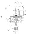
Fig. 2 is a diagram showing the vicinity of a neutron beam irradiation unit in the neutron capture therapy apparatus shown inFig. 1 . -
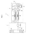
Fig. 3 is a diagram illustrating the measurement of neutron beams in the neutron capture therapy apparatus shown inFig. 1 . -
Fig. 4 is a diagram showing a scintillation detector. -
Fig. 5 is a diagram illustrating the conversion condition setting process in the neutron capture therapy apparatus shown inFig. 1 . -
Fig. 6 is a diagram illustrating the conversion condition setting process in the neutron capture therapy apparatus shown inFig. 1 . - Hereinafter, a neutron capture therapy apparatus and a neutron beam measuring method according to embodiments of the invention will be described in detail with reference to the accompanying diagrams.
- As shown in
Figs. 1 and2 , a neutroncapture therapy apparatus 1 that performs cancer treatment using a boron neutron capture therapy is an apparatus that performs cancer treatment by irradiating a part where boron is accumulated of a patient (subject) S, to whom boron (10B) hasbeenadministered, with neutron beams. The neutroncapture therapy apparatus 1 includes anirradiation chamber 2 for performing cancer treatment of the patient S restrained on a treatment table 3 by irradiating the patient S with a neutron beam N. A camera 4 for imaging the patient S is disposed in theirradiation chamber 2. The camera 4 is a CCD camera, for example. - A preparatory work, such as restraining the patient S on the treatment table 3, is performed in a preparation room (not shown) outside the
irradiation chamber 2, and the treatment table 3 on which the patient S is restrained is moved from the preparation room to theirradiation chamber 2. The neutroncapture therapy apparatus 1 includes a neutronbeam generation unit 10 that generates the neutron beam N for treatment and a neutronbeam irradiation unit 20 that irradiates the patient S, who is restrained on the treatment table 3 in theirradiation chamber 2, with the neutron beam N. - The neutron
beam generation unit 10 includes acyclotron 11 that generates a charged particle beam L, abeam transport path 12 for transporting the charged particle beam L generated by thecyclotron 11, a charged particlebeam scanning unit 13 that scans the charged particle beam L to control the irradiation of the charged particle beam L to a target T, and the target T. Thecyclotron 11 and thebeam transport path 12 are disposed in a charged particlebeam generation chamber 14 having an approximately rectangular shape, and the charged particlebeam generation chamber 14 is a closed space covered with a shielding wall W formed of concrete. The charged particlebeam scanning unit 13 controls the irradiation position of the charged particle beam L on the target T. - The
cyclotron 11 is an accelerator that accelerates charged particles, such as protons, to generate the charged particle beam L, such as a proton beam. Thecyclotron 11 can generate the charged particle beam L of 60 kW (= 30 MeV x 2 mA) having a beam radius of 40 mm, for example. Instead of thecyclotron 11, other accelerators, such as a synchrotron, a synchrocyclotron, and a linac, may be used. - One end of the
beam transport path 12 is connected to thecyclotron 11. Thebeam transport path 12 includes abeam adjusting unit 15 for adjusting the charged particle beam L. Thebeam adjusting unit 15 includes horizontal steering and horizontal and vertical steering for adjusting the axis of the charged particle beam L, a quadrupole electromagnet for suppressing the divergence of the charged particle beam L, and a four-way slit for shaping the charged particle beam L. Thebeam transport path 12 preferably has a function of transporting the charged particle beam L, and may not have thebeam adjusting unit 15. - The charged particle beam L transported by the
beam transport path 12 is irradiated to the target T by controlling the irradiation position using the charged particlebeam scanning unit 13. The charged particlebeam scanning unit 13 maybe omitted, so that the charged particle beam L is always irradiated to the same position of the target T. The target T generates the neutron beam N by the irradiation of the charged particle beam L. The target T is formed of beryllium (Be), lithium (Li), tantalum (Ta), or tungsten (W), and has a disc shape with a diameter of 160 mm, for example. The neutron beam N generated by the target T is irradiated toward the patient S in theirradiation chamber 2 by the neutronbeam irradiation unit 20. - The neutron
beam irradiation unit 20 includes amoderator 21 for decelerating the neutron beam N emitted from the target T and ashield 22 for shielding a radiation, such as the neutron beam N and gamma rays, so as not to be discharged to the outside. A moderator is formed by themoderator 21 and theshield 22. - The
moderator 21 is a laminated structure formed of a plurality of different materials, for example, and the material of themoderator 21 is appropriately selected depending on various conditions, such as the energy of the charged particle beam L. Specifically, for example, when the output from thecyclotron 11 is a proton beam of 30 MeV and a beryllium target is used as the target T, lead, iron, aluminum, or calcium fluoride can be used as materials of themoderator 21. When the output from thecyclotron 11 is a proton beam of 11 MeV and a beryllium target is used as the target T, heavy water (D2O) or lead fluoride can be used as materials of themoderator 21. - The
shield 22 is provided so as to surround themoderator 21, and has a function of shielding a radiation, such as the neutron beam N and gamma rays generated due to the generation of the neutron beam N, so as not to be discharged to the outside of theshield 22. At least a part of theshield 22 is embedded in the wall W1 that separates the charged particlebeam generation chamber 14 from theirradiation chamber 2. Awall 23 that forms a part of the side wall surface of theirradiation chamber 2 is provided between theirradiation chamber 2 and theshield 22. Acollimator mounting portion 23a as an output port of the neutron beam N is provided in thewall 23. Acollimator 31 for defining the irradiation field of the neutron beam N is fixed to thecollimator mounting portion 23a. - In the neutron
beam irradiation unit 20 described above, the charged particle beam L is irradiated to the target T, and the target T generates the neutron beam N. The neutron beam N generated by the target T is decelerated when passing through themoderator 21, and the neutron beam N emitted from themoderator 21 is irradiated to the patient S on the treatment table 3 after passing thecollimator 31. As the neutron beam N, it is possible to use an epithermal neutron beam or a thermal neutron beam with relatively low energy. - The treatment table 3 serves as a mounting table used in the neutron capture therapy, and can restrains the patient S at a predetermined posture and move from the preparation room (not shown) to the
irradiation chamber 2 with the restrained posture. The treatment table 3 includes abase portion 32 that forms the foundation of the treatment table 3, acaster 33 that can move thebase portion 32 on the floor, atop plate 34 on which the patient S is placed, and arobot arm 35 for moving thetop plate 34 relative to thebase portion 32. - The
base portion 32 includes a rectangularparallelepiped foundation portion 32a and a rectangularparallelepiped support portion 32b that is located above thefoundation portion 32a and supports therobot arm 35. Thesupport portion 32b is located inside thefoundation portion 32a in plan view, and therobot arm 35 is fixed to the upper surface of thesupport portion 32b. The fourcasters 33 are attached to the lower portion of thefoundation portion 32a. A driving force, such as a motor, may be applied to thecasters 33. In this case, since it is possible to make thecaster 33 roll easily on the floor, the movement of the treatment table 3 in a horizontal direction becomes easy. - The
robot arm 35 is for moving thetop plate 34 relative to thebase portion 32, and can move the patient S restrained on thetop plate 34 relative to thecollimator 31. Thetop plate 34 has an approximately rectangular shape in plan view, and the length of thetop plate 34 in the longitudinal direction is a length (for example, 2 m) allowing the patient S to lie down on thetop plate 34. The position of thetop plate 34 with respect to thebase portion 32 can be adjusted in a three-dimensional manner by the movement and rotation of therobot arm 35. In addition, a restraint (not shown) for restraining the patient S on thetop plate 34 is provided in thetop plate 34. - The neutron beam N having passed through an
opening 31a of thecollimator 31 is irradiated to the patient S restrained on thetop plate 34. Thecollimator 31 has, for example, an approximately rectangular parallelepiped shape, and includes theopening 31a for defining the irradiation range of the neutron beam N at the center. The outer shape of thecollimator 31 corresponds to the inner surface shape of thecollimator mounting portion 23a in thewall 23, and thecollimator 31 is fixed in a state of being fitted into thecollimator mounting portion 23a of thewall 23. - Incidentally, as shown in
Fig. 3 , in the neutroncapture therapy apparatus 1, the neutron dose of the neutron beam N is output to adisplay 51 of acomputer 50 in amonitoring room 5, which is a separate room from theirradiation chamber 2, in real time simultaneously with the irradiation of the neutron beam N to the patient S. Some of neutron beams irradiated from the neutronbeam irradiation unit 20 are irradiated to a scintillation detector (neutron beam detection unit) 41, and the other neutron beams are irradiated to the patient S. Ascintillator 41a of thescintillation detector 41 shown inFig. 4 is affixed to the head of the patient S, for example. Thescintillator 41a is a phosphor that converts the neutron beam, which is incident on thescintillator 41a, into light. According to the dose of incident neutron beams, internal crystal becomes excited, thereby generating scintillation light. - The
scintillation detector 41 includes thescintillator 41a described above, alight guide 41b for transmitting light from thescintillator 41a, and aphotodetector 41c that outputs an electrical signal E by performing photoelectric conversion of the light transmitted by thelight guide 41b. Thelight guide 41b is formed of, for example, a bundle of flexible optical fibers, and transmits the light generated by thescintillator 41a to thephotodetector 41c. Thelight guide 41b extends, for example, from theirradiation chamber 2 to themonitoring room 5, and is connected to thephotodetector 41c in themonitoring room 5. Thephotodetector 41c detects light from thelight guide 41b, and outputs the electrical signal to asignal processing circuit 42 as a pulse signal. As thephotodetector 41c, for example, a phototube or a photomultiplier tube can be used. - The
signal processing circuit 42 has a function of shaping the pulse signal from thescintillation detector 41 and outputting the result to a neutronbeam measuring unit 43 and a noise removal function, and is disposed at a position adjacent to thecomputer 50 in themonitoring room 5, for example. The neutronbeam measuring unit 43 is software in thecomputer 50, and measures the amount of neutron beam N irradiated to thescintillator 41a in real time by counting the pulses of the pulse signal received from thesignal processing circuit 42. - The neutron
beam measuring unit 43 measures the amount of neutron beam N as the number of signals that thescintillation detector 41 outputs per unit time (count rate). That is, the neutronbeam measuring unit 43 measures data regarding the signal of the scintillation detector 41 (hereinafter, referred to as signal data), and outputs the measured signal data of thescintillation detector 41 to a neutrondose output unit 44. A real-timedose output unit 40 is formed by thescintillation detector 41, thesignal processing circuit 42, the neutronbeam measuring unit 43, and the neutrondose output unit 44 described above. - In the
scintillation detector 41, since the optical fiber or the like of thelight guide 41b deteriorates with an increase in the number of times of irradiation of the neutron beam N, the detection efficiency of the neutron beam N is reduced. If the detection efficiency of the neutron beam N is reduced as described above, signal data from thescintillation detector 41 with respect to the amount of neutron beam N actually irradiated to thescintillation detector 41 changes gradually. This causes a problem in that the measurement accuracy of the neutron beam N is reduced. - As a method of measuring the neutron beam N, for example, there is a method of measuring the amount of irradiated neutron beam N by mounting the gold wire on the head of the patient S and measuring the amount of activation of the gold wire. Thus, the method of measuring the amount of the neutron beam N by measuring the amount of activation of gold wire is a method that cannot disturb the neutron field easily. By measuring the amount of gamma rays emitted from the gold wire, it is possible to reliably detect the neutron dose. However, this method has a problem in that it takes time for the activation of gold wire and real-time measurement cannot be performed since the amount of neutron beam N cannot be measured during the irradiation of the neutron beam N. In addition, since the total amount of the dose of neutron beam N is calculated from the amount of activation of gold wire afterward, the average value of the dose per unit time can be calculated by dividing the total amount of the dose by the irradiation time. However, there is also a problem in that a change in dose per predetermined time cannot be calculated.
- Therefore, in order to solve the problems described above, in the neutron
capture therapy apparatus 1, the real-timedose output unit 40 can output the neutron dose in real time. In addition, the method of measuring the neutron beam N using the neutroncapture therapy apparatus 1 includes a real-time dose output step of outputting the neutron dose in real time. That is, when the signal data of thescintillation detector 41 is received from the neutronbeam measuring unit 43, the neutrondose output unit 44 of the real-timedose output unit 40 converts the signal data into the neutron dose of the neutron beam N using acorrection coefficient 45 set in advance and outputs the dose of the neutron beam N in real time. - The
correction coefficient 45 functions as a conversion condition for converting the signal of thescintillation detector 41 into the dose of the neutron beam N irradiated to the patient S, and shows the relationship between the signal data of thescintillation detector 41 and the dose of the neutron beam N irradiated to the patient S. Thecorrection coefficient 45 is set in advance in calibration work (conversion condition setting step) before performing the treatment. Here, "before performing the treatment" indicates "before each treatment". Alternatively, calibration may be performed every predetermined number of times of treatment instead of the "before each treatment" , or calibration maybe performed after a predetermined time elapses. Hereinafter, this calibration work and a method of measuring the neutron beam N when treating the patient S using the neutron beam N will be described. - The calibration work is performed when the patient S is not present in the
irradiation chamber 2, for example. As shown inFigs. 5 and6 , in the calibration work, a correction coefficient setting unit (conversion condition setting unit) 60 sets thecorrection coefficient 45 before treatment. The correctioncoefficient setting unit 60 includes a gold wire (metal member) 61 that is a thin wire of gold (Au), a gamma ray detector (gamma ray detection section) 62 that detects gamma rays, asignal processing circuit 63 that processes a signal from thegamma ray detector 62, a neutrondose measurement section 64 that measures the dose of the neutron beam N, and a correction coefficient calculation section (conversion condition calculation section) 65 that calculates thecorrection coefficient 45. - As shown in
Fig. 5 , thescintillation detector 41 is disposed at a position where the head of the patient S is located, for example. Thegold wire 61 is disposed adjacent to thescintillation detector 41. Thescintillation detector 41 and thegold wire 61 are disposed such that their positions and directions with respect to theopening 31a of thecollimator 31 are the same. Under such conditions, thescintillation detector 41 and thegold wire 61 are irradiated with the neutron beam N for a fixed period of time (for example, 10 minutes) (second neutron beam irradiation step). When thescintillation detector 41 is irradiated with the neutron beam N for a fixed period of time, the neutronbeam measuring unit 43 measures the signal data of thescintillation detector 41 in real time. - As shown in
Fig. 6 , after the neutron beam N is irradiated for a fixed period of time, the irradiation of the neutron beam N to thescintillation detector 41 and thegold wire 61 is stopped. Then, thegold wire 61 activated by irradiation of the neutron beam N is taken away from theirradiation chamber 2 , and is disposed in the holder of themonitoring room 5. After placing thegold wire 61 in the holder, thecorrection coefficient 45 is calculated by thegamma ray detector 62, thesignal processing circuit 63, the neutrondose measurement section 64, and the correctioncoefficient calculation section 65. The process of calculating thecorrection coefficient 45 is automatically performed when thecomputer 50 is operated after thegold wire 61 is disposed. - The
gamma ray detector 62 detects gamma rays generated from the activated gold wire 61 (gamma ray detection step). As thegamma ray detector 62, a semiconductor detector, such as a germanium detector, can be used. For example, when gamma rays are incident on the semiconductor crystal of thegamma ray detector 62, an electrical signal is generated. Thegamma ray detector 62 outputs the electrical signal to thesignal processing circuit 63. Thegamma ray detector 62 and thesignal processing circuit 63 are disposed at positions adjacent to thecomputer 50 in themonitoring room 5, for example. - The
signal processing circuit 63 has a function of shaping the electrical signal from thegamma ray detector 62 and outputting the result to the neutrondose measurement section 64 and a noise removal function. The neutrondose measurement section 64 receives the electrical signal shaped by thesignal processing circuit 63 and measures the dose of the neutron beam N irradiated to thegold wire 61. The neutrondose measurement section 64 measures the amount of neutron beam N as the amount of neutron beam N per unit area, that is, a neutron flux. The unit of the neutron dose measured by the neutrondose measurement section 64 is N/cm2. The dose of the neutron beam N measured by the neutrondose measurement section 64 is output to the correctioncoefficient calculation section 65. - The dose of the neutron beam N measured by the neutron
dose measurement section 64 and the signal data of thescintillation detector 41 measured by the neutronbeam measuring unit 43 are input to the correctioncoefficient calculation section 65. Then, the correctioncoefficient calculation section 65 calculates thecorrection coefficient 45 for matching the signal of thescintillation detector 41 and the neutron dose with each other from the signal data of thescintillation detector 41 and the dose of the neutron beam N (conversion condition calculation step). After thecorrection coefficient 45 is calculated by the correctioncoefficient calculation section 65 as described above, a series of calibration work is completed. Thecorrection coefficient 45 calculated herein is a neutron dose, which is measured by the neutrondose measurement section 64, with respect to the unit data (the number of light beams per unit time) measured by the neutronbeam measuring unit 43. - After the calibration work is completed as described above, a preparatory work, such as restraining the patient S on the treatment table 3, is performed. After moving the treatment table 3 on which the patient S is restrained into the
irradiation chamber 2, alignment of the patient S with respect to thecollimator 31 is performed by driving therobot arm 35, so that the head of the patient S is close to theopening 31a of thecollimator 31 and the irradiation position of the neutron beam N is located in the affected area of the patient S. Then, the patient S is irradiated with the neutron beam N to start the treatment. - Specifically, as shown in
Fig. 1 , thecyclotron 11 generates the charged particle beam L, and the charged particle beam L is irradiated to the target T through thebeam transport path 12 and the charged particlebeam scanning unit 13. Then, as shown inFig. 2 , the target T generates the neutron beam N (neutron beam generation step). The neutron beam N generated by the target T is decelerated by themoderator 21, and is then irradiated to the patient S after the irradiation range is defined by theopening 31a of the collimator 31 (first neutron beam irradiation step). - As shown in
Fig. 3 , the neutron beam N irradiated from thecollimator 31 is incident on thescintillation detector 41. When the neutron beam N is incident on thescintillation detector 41, the signal data of thescintillation detector 41 is transmitted to the neutronbeam measuring unit 43 through thesignal processing circuit 42 in real time. Then, the signal data of thescintillation detector 41 is converted into the dose of the neutron beam N using thecorrection coefficient 45 by the neutrondose output unit 44, and is output to thedisplay 51 of thecomputer 50 in real time (real-time dose output step). Thus, since the dose of the neutron beam N is output to thedisplay 51 in real time, a doctor or the like can always see the dose of the neutron beam N during treatment. - As described above, according to the neutron
capture therapy apparatus 1 and the neutron beam measuring method using the neutroncapture therapy apparatus 1, thescintillation detector 41 detects the neutron beam N irradiated from the neutronbeam irradiation unit 20 and outputs the signal in real time, the neutrondose output unit 44 converts the signal data into a neutron dose using thecorrection coefficient 45 set in advance, and the neutron dose is output to thedisplay 51 of thecomputer 50 in real time. Thus, due to the real-timedose output unit 40 including thescintillation detector 41 and the neutrondose output unit 44, the neutron dose of the neutron beam N can be output in real time when irradiating the neutron beam N to perform treatment. - The correction
coefficient setting unit 60 includes thegamma ray detector 62 that detects gamma rays emitted from thegold wire 61 activated by irradiation of the neutron beam N, and modifies (updates) thecorrection coefficient 45 based on the signal data, which is output from thescintillation detector 41 that detects the neutron beam N, and the neutron dose acquired based on the gamma rays detected by thegamma ray detector 62. By modifying thecorrection coefficient 45 using the signal data, which is output from thescintillation detector 41 that detects the neutron beam N, and the neutron dose obtained from thegold wire 61, the signal data of thescintillation detector 41 is corrected into the neutron dose using the modifiedcorrection coefficient 45 even if the detection efficiency of thescintillation detector 41 that outputs a signal is lowered. That is, even if the detection efficiency of thescintillation detector 41 is lowered, it is possible to accurately calculate the neutron dose by resetting thecorrection coefficient 45. Therefore, it is possible to eliminate a difference between the neutron dose actually irradiated and the measured neutron dose. Thus, since the signal data of thescintillation detector 41 is output after being converted into the neutron dose using the modifiedcorrection coefficient 45, it is possible to avoid a situation where the measurement accuracy of neutron beams is reduced. - In the neutron
capture therapy apparatus 1, thescintillator 41a that generates a light signal when neutron beams are irradiated is used as a neutron beam detection unit. Since thescintillator 41a can be easily miniaturized and can be easily processed into various shapes, it is possible to reduce the size of the apparatus by using thescintillator 41a. - The neutron
beam measuring unit 43, the neutrondose output unit 44, the neutrondose measurement section 64, and the correctioncoefficient calculation section 65 are software in thecomputer 50, and thesignal processing circuit 42, thegamma ray detector 62 , and thesignal processing circuit 63 are disposed at positions adjacent to thecomputer 50. Thus, each device to perform calibration work or measurement work of the neutron beam N is collected within themonitoring room 5. The calibration work or the measurement work of the neutron beam N is automatically performed by each device in themonitoring room 5 when a setting of thescintillation detector 41 or thegold wire 61 is performed. Thus, the neutroncapture therapy apparatus 1 has a configuration to easily perform the calibration work or the measurement work of the neutron beam N. - While the embodiments of the invention have been described above, the invention is not limited to the above-described embodiments, and various modifications can be made without departing from the concept of the invention defined in the appended claims.
- In the embodiment described above, the calibration work is performed when the patient S is not present in the
irradiation chamber 2. However, the timing of the calibration work can be appropriately changed. For example, the calibration work may be performed during treatment for which the patient S is present in theirradiation chamber 2. That is, assuming that the entire irradiation time is 30 minutes, it is possible to perform calibration work using thegold wire 61 in the first 10 minutes and perform real-time measurement of the neutron dose in the subsequent 20 minutes. - In addition, although the
gold wire 61 is used as a metal member of the correctioncoefficient setting unit 60, it is also possible to use a metal member having a different shape from thegold wire 61, for example, a gold leaf. Materials of the metal member are not limited to gold, and it is possible to use any material that is activated when neutron beams are irradiated. For example, manganese can be used. - In the embodiment described above, the correction
coefficient calculation section 65 calculates thecorrection coefficient 45 from the signal data of thescintillation detector 41 and the dose of the neutron beam N . However, it is also possible to calculate thecorrection coefficient 45 from those other than the signal of thescintillation detector 41. For example, in the second and subsequent calculations of thecorrection coefficient 45, thecorrection coefficient 45 can be calculated from the neutron dose output from the neutrondose output unit 44 last and the neutron dose obtained this time by the neutrondose measurement section 64. As a conversion condition for converting the signal data into the neutron dose, for example, an equation and the like can be used without being limited to thecorrection coefficient 45. - In addition, although the
scintillation detector 41 is used as a neutron beam detection unit that receives neutron beams and generates a signal in real time, an ionization chamber may be used instead of thescintillation detector 41. - In the
monitoring room 5, thecomputer 50, thegamma ray detector 62, and thesignal processing circuits beam generation unit 10 and the neutronbeam irradiation unit 20 or the arrangement of each device in the neutroncapture therapy apparatus 1.
Claims (3)
- A neutron capture therapy apparatus that irradiates a subj ect with a neutron beam, comprising:a neutron beam generation unit that generates the neutron beam;a neutron beam irradiation unit that irradiates the neutron beam generated by the neutron beam generation unit toward the subject;a real-time dose output unit that includes a neutron beam detection unit, which detects the neutron beam irradiated from the neutron beam irradiation unit and outputs a signal in real time, and a neutron dose output unit, which converts the signal output from the neutron beam detection unit into a neutron dose using a conversion condition set in advance and outputs the neutron dose in real time; anda conversion condition settingunit that sets the conversion condition,wherein the conversion condition setting unit includes a gamma ray detection section that detects a gamma ray emitted from a metal member activated by irradiation of the neutron beam, and modifies the conversion condition based on a signal, which is output from the neutron beam detection unit by irradiation of the neutron beam, and a neutron dose of the neutron beam, which is acquired based on the gamma ray detected by the gamma ray detection section.
- The neutron capture therapy apparatus according to claim 1,
wherein the neutron beam detection unit is a scintillator that generates a light signal as the signal by irradiation of the neutron beam. - A neutron beam measuring method in a neutron capture therapy apparatus that irradiates a subject with a neutron beam, comprising:a neutron beam generation step of generating the neutron beam;a first neutron beam irradiation step of irradiating the neutron beam generated in the neutron beam generation step toward the subject;a real-time dose output step of causing a neutron beam detection unit to output a signal in real time by detecting the neutron beam irradiated in the first neutron beam irradiation step, converting the signal into a neutron dose using a conversion condition set in advance, and outputting the neutron dose in real time; anda conversion condition setting step of setting the conversion condition,wherein the conversion condition setting step includes a second neutron beam irradiation step of irradiating the neutron beam detection unit and a metal member with the neutron beam, a gamma ray detection step of detecting a gamma ray emitted from the metal member activated by irradiation of the neutron beam in the second neutron beam irradiation step, and a conversion condition calculation step of modifying the conversion condition based on a signal, which is output from the neutron beam detection unit by irradiation of the neutron beam, and a neutron dose of the neutron beam, which is acquired based on the gamma ray detected in the gamma ray detection step.
Applications Claiming Priority (1)
| Application Number | Priority Date | Filing Date | Title |
|---|---|---|---|
| JP2013108339A JP6042269B2 (en) | 2013-05-22 | 2013-05-22 | Neutron capture therapy device and neutron beam measurement method |
Publications (2)
| Publication Number | Publication Date |
|---|---|
| EP2805745A1 true EP2805745A1 (en) | 2014-11-26 |
| EP2805745B1 EP2805745B1 (en) | 2017-04-26 |
Family
ID=50685840
Family Applications (1)
| Application Number | Title | Priority Date | Filing Date |
|---|---|---|---|
| EP14168169.2A Not-in-force EP2805745B1 (en) | 2013-05-22 | 2014-05-13 | Neutron capture therapy apparatus |
Country Status (5)
| Country | Link |
|---|---|
| EP (1) | EP2805745B1 (en) |
| JP (1) | JP6042269B2 (en) |
| KR (2) | KR20140137292A (en) |
| CN (1) | CN104174121B (en) |
| TW (1) | TWI520758B (en) |
Cited By (18)
| Publication number | Priority date | Publication date | Assignee | Title |
|---|---|---|---|---|
| GB2551119A (en) * | 2016-06-01 | 2017-12-13 | Elekta ltd | Radiotherapy calibration |
| EP3254729A4 (en) * | 2015-05-04 | 2018-04-18 | Neuboron Medtech Ltd. | Beam shaping body for neutron capture therapy |
| EP3342459A4 (en) * | 2015-09-28 | 2018-10-10 | Neuboron Medtech Ltd. | Radiation detection system and radiation detection method for neutron capture therapy system |
| CN108969899A (en) * | 2017-06-05 | 2018-12-11 | 南京中硼联康医疗科技有限公司 | Beam-shaping body for neutron capture treatment |
| US10155123B2 (en) | 2015-10-29 | 2018-12-18 | Sumitomo Heavy Industries, Ltd. | Neutron capture therapy system |
| EP3384960A4 (en) * | 2015-12-30 | 2018-12-19 | Neuboron Medtech Ltd. | NEUTRON CAPTURE THERAPY SYSTEM FOR ELIMINATING AMYLOID ß-PROTEIN |
| WO2019016326A1 (en) * | 2017-07-21 | 2019-01-24 | Varian Medical Systems Particle Therapy Gmbh | Particle beam monitoring systems and methods |
| CN109568808A (en) * | 2015-09-11 | 2019-04-05 | 南京中硼联康医疗科技有限公司 | Hot-press sintering equipment and sintering process |
| EP3395407A4 (en) * | 2016-01-15 | 2019-05-15 | Neuboron Medtech Ltd. | Radiation ray detection system for neutron capture therapy system and method for detecting radiation rays |
| EP3566748A4 (en) * | 2017-06-05 | 2019-12-11 | Neuboron Medtech Ltd. | Beam shaping assembly for neutron capture therapy |
| US10609806B2 (en) | 2017-07-21 | 2020-03-31 | Varian Medical Systems Particle Therapy Gmbh | Energy modulation of a cyclotron beam |
| CN110967727A (en) * | 2019-12-09 | 2020-04-07 | 中国原子能科学研究院 | Gamma energy spectrometer for boron neutron capture treatment irradiation beam |
| JP2020130572A (en) * | 2019-02-19 | 2020-08-31 | 住友重機械工業株式会社 | Neutron capture therapy system |
| US10843011B2 (en) | 2017-07-21 | 2020-11-24 | Varian Medical Systems, Inc. | Particle beam gun control systems and methods |
| US10898730B2 (en) | 2017-07-21 | 2021-01-26 | Varian Medical Systems International Ag | Triggered treatment systems and methods |
| CN113031051A (en) * | 2019-12-25 | 2021-06-25 | 住友重机械工业株式会社 | Correction device, treatment planning device, and correction method |
| CN113877080A (en) * | 2020-07-03 | 2022-01-04 | 中硼(厦门)医疗器械有限公司 | Neutron dose detection device and neutron capture treatment equipment |
| US11740370B2 (en) | 2015-09-28 | 2023-08-29 | Neuboron Medtech Ltd. | Radiation detection system and radiation detection method for neutron capture therapy system |
Families Citing this family (22)
| Publication number | Priority date | Publication date | Assignee | Title |
|---|---|---|---|---|
| CN107497060B (en) * | 2014-12-08 | 2020-02-28 | 南京中硼联康医疗科技有限公司 | Beam shaping body for neutron capture therapy |
| CN108325092B (en) * | 2014-12-08 | 2020-08-07 | 南京中硼联康医疗科技有限公司 | Beam shaping body for neutron capture therapy |
| JP6430264B2 (en) * | 2015-01-19 | 2018-11-28 | 住友重機械工業株式会社 | Negative ion source device |
| JP6565113B2 (en) * | 2015-03-05 | 2019-08-28 | 住友重機械工業株式会社 | Neutron capture therapy device |
| JP6613464B2 (en) * | 2015-03-06 | 2019-12-04 | 住友重機械工業株式会社 | Neutron beam detector |
| JP6605221B2 (en) * | 2015-03-31 | 2019-11-13 | 住友重機械工業株式会社 | Neutron capture therapy device |
| CN110251847A (en) * | 2015-05-04 | 2019-09-20 | 南京中硼联康医疗科技有限公司 | Beam-shaping body for neutron capture treatment |
| US10294419B2 (en) * | 2015-08-28 | 2019-05-21 | Denka Company Limited | Charged particle radiation measuring method and charged particle radiation measuring device |
| CN108325095B (en) * | 2015-09-30 | 2020-08-07 | 南京中硼联康医疗科技有限公司 | Beam shaping body for neutron capture therapy |
| CN105445777B (en) * | 2015-12-01 | 2018-06-05 | 南京航空航天大学 | A kind of boron neutron capture therapy Dosimetry |
| CN106980136B (en) * | 2016-01-15 | 2024-02-20 | 南京中硼联康医疗科技有限公司 | Radiation detection system for neutron capture treatment system and detection method thereof |
| CN106730372B (en) * | 2016-12-31 | 2023-06-27 | 广东恒聚医疗科技有限公司 | Positioning system for radiotherapy |
| EP3583981B1 (en) * | 2017-05-12 | 2020-12-23 | Neuboron Medtech Ltd. | Photon emission detection device and boron neutron capture therapy system having same |
| WO2018211832A1 (en) * | 2017-05-16 | 2018-11-22 | 住友重機械工業株式会社 | Neutron capture therapy system |
| JP6953902B2 (en) * | 2017-08-29 | 2021-10-27 | 東京電力ホールディングス株式会社 | Neutron detector |
| KR102187572B1 (en) | 2019-01-24 | 2020-12-07 | 한국원자력연구원 | A security inspection device of detecting hazardous materials using radiation |
| KR102178632B1 (en) | 2019-02-08 | 2020-11-16 | 한국원자력의학원 | Neutron Capture and Therapy Device with Multiple Compact Cyclotron and control method for that |
| JP7378729B2 (en) * | 2019-12-25 | 2023-11-14 | 住友重機械工業株式会社 | Neutron beam measurement device and neutron beam measurement method |
| CN113952636B (en) * | 2020-07-20 | 2023-08-08 | 中硼(厦门)医疗器械有限公司 | Radiation therapy system and safety interlocking control method thereof |
| CN116999720A (en) * | 2020-11-25 | 2023-11-07 | 中硼(厦门)医疗器械有限公司 | Neutron capture therapy device |
| WO2022215192A1 (en) * | 2021-04-07 | 2022-10-13 | 三菱電機株式会社 | Neutron flux measuring apparatus |
| CN116338760A (en) * | 2021-12-22 | 2023-06-27 | 中硼(厦门)医疗器械有限公司 | Neutron dose measuring method and device |
Citations (2)
| Publication number | Priority date | Publication date | Assignee | Title |
|---|---|---|---|---|
| JP2004233168A (en) | 2003-01-29 | 2004-08-19 | Japan Science & Technology Agency | Neutron shielding plate used for neutron capture therapy, neutron capture therapy performed on mammals other than human and neutron irradiation equipment for the therapy |
| WO2012014671A1 (en) * | 2010-07-28 | 2012-02-02 | 住友重機械工業株式会社 | Neutron ray irradiation device, and method for control of neutron ray irradiation device |
Family Cites Families (5)
| Publication number | Priority date | Publication date | Assignee | Title |
|---|---|---|---|---|
| CN1117591C (en) * | 1999-09-28 | 2003-08-13 | 王乔生 | Automatic fast-neutron radiotherapeutic equipment with near remote-control function |
| JP2004337268A (en) * | 2003-05-14 | 2004-12-02 | Atsushi Hata | Neutron capture therapeutic apparatus using antibody namely monoclonal antibody |
| US8188440B2 (en) * | 2006-09-20 | 2012-05-29 | Siemens Medical Solutions Usa, Inc. | Neutron dosimetry for radiotherapy |
| CN102176047B (en) * | 2011-03-04 | 2013-04-17 | 中国原子能科学研究院 | Neutron personal dosimeter with energy compensation |
| JP5873481B2 (en) * | 2011-04-25 | 2016-03-01 | 住友重機械工業株式会社 | Charged particle beam irradiation equipment |
-
2013
- 2013-05-22 JP JP2013108339A patent/JP6042269B2/en not_active Expired - Fee Related
-
2014
- 2014-04-15 TW TW103113668A patent/TWI520758B/en not_active IP Right Cessation
- 2014-04-18 KR KR20140046559A patent/KR20140137292A/en active Application Filing
- 2014-04-21 CN CN201410160216.4A patent/CN104174121B/en active Active
- 2014-05-13 EP EP14168169.2A patent/EP2805745B1/en not_active Not-in-force
-
2016
- 2016-08-22 KR KR1020160106041A patent/KR20160103960A/en not_active Application Discontinuation
Patent Citations (2)
| Publication number | Priority date | Publication date | Assignee | Title |
|---|---|---|---|---|
| JP2004233168A (en) | 2003-01-29 | 2004-08-19 | Japan Science & Technology Agency | Neutron shielding plate used for neutron capture therapy, neutron capture therapy performed on mammals other than human and neutron irradiation equipment for the therapy |
| WO2012014671A1 (en) * | 2010-07-28 | 2012-02-02 | 住友重機械工業株式会社 | Neutron ray irradiation device, and method for control of neutron ray irradiation device |
Non-Patent Citations (3)
| Title |
|---|
| GÃ MEZ F ET AL: "A new active method for the measurement of slow-neutron fluence in modern radiotherapy treatment rooms; New method for neutron measurement in radiotherapy", PHYSICS IN MEDICINE AND BIOLOGY, INSTITUTE OF PHYSICS PUBLISHING, BRISTOL GB, vol. 55, no. 4, 21 February 2010 (2010-02-21), pages 1025 - 1039, XP020171781, ISSN: 0031-9155 * |
| ISHIKAWA M ET AL: "Development of real-time thermal neutron monitor using boron-loaded plastic scintillator with optical fiber for boron neutron capture therapy", APPLIED RADIATION AND ISOTOPES, ELSEVIER, OXFORD, GB, vol. 61, no. 5, 1 November 2004 (2004-11-01), pages 775 - 779, XP004526447, ISSN: 0969-8043, DOI: 10.1016/J.APRADISO.2004.05.053 * |
| MATSUMOTO T ET AL: "A new monitoring system for the thermal neutron fluence rate and gamma dose rate in boron neutron capture therapy", PHYSICS IN MEDICINE AND BIOLOGY, INSTITUTE OF PHYSICS PUBLISHING, BRISTOL GB, vol. 33, no. 4, 1 April 1988 (1988-04-01), pages 427 - 435, XP020023328, ISSN: 0031-9155, DOI: 10.1088/0031-9155/33/4/003 * |
Cited By (36)
| Publication number | Priority date | Publication date | Assignee | Title |
|---|---|---|---|---|
| RU2682972C1 (en) * | 2015-05-04 | 2019-03-25 | Неуборон Медтек Лтд. | Applied in the neutron capture therapy beam formation element |
| EP3254729A4 (en) * | 2015-05-04 | 2018-04-18 | Neuboron Medtech Ltd. | Beam shaping body for neutron capture therapy |
| US10328286B2 (en) | 2015-05-04 | 2019-06-25 | Neuboron Medtech Ltd. | Beam shaping assembly for neutron capture therapy |
| US10617893B2 (en) | 2015-05-04 | 2020-04-14 | Neuboron Medtech Ltd. | Beam shaping assembly for neutron capture therapy |
| EP3570294A1 (en) * | 2015-05-04 | 2019-11-20 | Neuboron Medtech Ltd. | Beam shaping body for neutron capture therapy |
| CN109568808A (en) * | 2015-09-11 | 2019-04-05 | 南京中硼联康医疗科技有限公司 | Hot-press sintering equipment and sintering process |
| CN109568812B (en) * | 2015-09-11 | 2020-08-11 | 南京中硼联康医疗科技有限公司 | Beam shaping body for neutron capture therapy |
| CN109568809B (en) * | 2015-09-11 | 2020-08-07 | 南京中硼联康医疗科技有限公司 | Neutron retarding material |
| CN109568812A (en) * | 2015-09-11 | 2019-04-05 | 南京中硼联康医疗科技有限公司 | Beam-shaping body for neutron capture treatment |
| CN109568809A (en) * | 2015-09-11 | 2019-04-05 | 南京中硼联康医疗科技有限公司 | The slow material of neutron |
| US11740370B2 (en) | 2015-09-28 | 2023-08-29 | Neuboron Medtech Ltd. | Radiation detection system and radiation detection method for neutron capture therapy system |
| EP3342459A4 (en) * | 2015-09-28 | 2018-10-10 | Neuboron Medtech Ltd. | Radiation detection system and radiation detection method for neutron capture therapy system |
| US10155123B2 (en) | 2015-10-29 | 2018-12-18 | Sumitomo Heavy Industries, Ltd. | Neutron capture therapy system |
| EP3384960A4 (en) * | 2015-12-30 | 2018-12-19 | Neuboron Medtech Ltd. | NEUTRON CAPTURE THERAPY SYSTEM FOR ELIMINATING AMYLOID ß-PROTEIN |
| US10537750B2 (en) | 2016-01-15 | 2020-01-21 | Neuboron Medtech Ltd. | Radiation detection system for neutron capture therapy system and detection method thereof |
| RU2697763C1 (en) * | 2016-01-15 | 2019-08-19 | Нойборон Медтех Лтд. | Radiation detection system for neutron capture therapy system and method of radiation detection |
| EP3632509A1 (en) | 2016-01-15 | 2020-04-08 | Neuboron Medtech Ltd. | Neutron capture therapy system |
| EP3395407A4 (en) * | 2016-01-15 | 2019-05-15 | Neuboron Medtech Ltd. | Radiation ray detection system for neutron capture therapy system and method for detecting radiation rays |
| GB2551119B (en) * | 2016-06-01 | 2023-06-07 | Elekta ltd | Radiotherapy calibration |
| GB2551119A (en) * | 2016-06-01 | 2017-12-13 | Elekta ltd | Radiotherapy calibration |
| US11559705B2 (en) | 2017-06-05 | 2023-01-24 | Neuboron Medtech Ltd. | Neutron capture therapy system |
| EP3566748A4 (en) * | 2017-06-05 | 2019-12-11 | Neuboron Medtech Ltd. | Beam shaping assembly for neutron capture therapy |
| CN108969899A (en) * | 2017-06-05 | 2018-12-11 | 南京中硼联康医疗科技有限公司 | Beam-shaping body for neutron capture treatment |
| US10702716B2 (en) | 2017-07-21 | 2020-07-07 | Varian Medical Systems Particle Therapy Gmbh | Particle beam monitoring systems and methods |
| US10245448B2 (en) | 2017-07-21 | 2019-04-02 | Varian Medical Systems Particle Therapy Gmbh | Particle beam monitoring systems and methods |
| WO2019016326A1 (en) * | 2017-07-21 | 2019-01-24 | Varian Medical Systems Particle Therapy Gmbh | Particle beam monitoring systems and methods |
| US10843011B2 (en) | 2017-07-21 | 2020-11-24 | Varian Medical Systems, Inc. | Particle beam gun control systems and methods |
| US10898730B2 (en) | 2017-07-21 | 2021-01-26 | Varian Medical Systems International Ag | Triggered treatment systems and methods |
| US10609806B2 (en) | 2017-07-21 | 2020-03-31 | Varian Medical Systems Particle Therapy Gmbh | Energy modulation of a cyclotron beam |
| CN110709133A (en) * | 2017-07-21 | 2020-01-17 | 瓦里安医疗系统粒子疗法有限责任公司 | Particle beam monitoring system and method |
| US11478664B2 (en) | 2017-07-21 | 2022-10-25 | Varian Medical Systems, Inc. | Particle beam gun control systems and methods |
| JP2020130572A (en) * | 2019-02-19 | 2020-08-31 | 住友重機械工業株式会社 | Neutron capture therapy system |
| CN110967727A (en) * | 2019-12-09 | 2020-04-07 | 中国原子能科学研究院 | Gamma energy spectrometer for boron neutron capture treatment irradiation beam |
| CN113031051A (en) * | 2019-12-25 | 2021-06-25 | 住友重机械工业株式会社 | Correction device, treatment planning device, and correction method |
| CN113877080B (en) * | 2020-07-03 | 2023-06-02 | 中硼(厦门)医疗器械有限公司 | Neutron dose detection device and neutron capture treatment equipment |
| CN113877080A (en) * | 2020-07-03 | 2022-01-04 | 中硼(厦门)医疗器械有限公司 | Neutron dose detection device and neutron capture treatment equipment |
Also Published As
| Publication number | Publication date |
|---|---|
| KR20140137292A (en) | 2014-12-02 |
| JP2014228401A (en) | 2014-12-08 |
| EP2805745B1 (en) | 2017-04-26 |
| CN104174121B (en) | 2017-05-24 |
| JP6042269B2 (en) | 2016-12-14 |
| CN104174121A (en) | 2014-12-03 |
| TW201444601A (en) | 2014-12-01 |
| TWI520758B (en) | 2016-02-11 |
| KR20160103960A (en) | 2016-09-02 |
Similar Documents
| Publication | Publication Date | Title |
|---|---|---|
| EP2805745B1 (en) | Neutron capture therapy apparatus | |
| TWI527606B (en) | Neutron capture therapy device | |
| JP6052933B2 (en) | Neutron beam detection device and neutron capture therapy device | |
| JP6938627B2 (en) | Neutron capture therapy system | |
| WO2017073683A1 (en) | Neutron capture therapy system | |
| TW201840348A (en) | Neutron capture therapy system and gamma ray detector for neutron capture therapy | |
| JP6144114B2 (en) | Neutron capture therapy device and irradiation object position correction method | |
| CN113877080B (en) | Neutron dose detection device and neutron capture treatment equipment | |
| TWI666464B (en) | Neutron beam detection system and setting method of neutron beam detection system | |
| JP2014190754A (en) | Neutron dosimetry device and neutron capture therapy device | |
| JP6465283B2 (en) | Radiation therapy system | |
| JP2010012056A (en) | Charged particle beam irradiation system | |
| JP7021989B2 (en) | Neutron capture therapy system and neutron detector | |
| JP2022189968A (en) | Neutron capture therapy system | |
| JP6532008B2 (en) | Phantom device for neutron beam measurement | |
| JP2019105476A (en) | Neutron beam detection device | |
| JP7248470B2 (en) | Neutron detector | |
| JP2022078886A (en) | Particle beam monitoring system, particle beam monitoring method, and particle beam treatment system |
Legal Events
| Date | Code | Title | Description |
|---|---|---|---|
| PUAI | Public reference made under article 153(3) epc to a published international application that has entered the european phase |
Free format text: ORIGINAL CODE: 0009012 |
|
| 17P | Request for examination filed |
Effective date: 20140513 |
|
| AK | Designated contracting states |
Kind code of ref document: A1 Designated state(s): AL AT BE BG CH CY CZ DE DK EE ES FI FR GB GR HR HU IE IS IT LI LT LU LV MC MK MT NL NO PL PT RO RS SE SI SK SM TR |
|
| AX | Request for extension of the european patent |
Extension state: BA ME |
|
| 17Q | First examination report despatched |
Effective date: 20160418 |
|
| GRAP | Despatch of communication of intention to grant a patent |
Free format text: ORIGINAL CODE: EPIDOSNIGR1 |
|
| INTG | Intention to grant announced |
Effective date: 20161108 |
|
| GRAS | Grant fee paid |
Free format text: ORIGINAL CODE: EPIDOSNIGR3 |
|
| GRAA | (expected) grant |
Free format text: ORIGINAL CODE: 0009210 |
|
| AK | Designated contracting states |
Kind code of ref document: B1 Designated state(s): AL AT BE BG CH CY CZ DE DK EE ES FI FR GB GR HR HU IE IS IT LI LT LU LV MC MK MT NL NO PL PT RO RS SE SI SK SM TR |
|
| REG | Reference to a national code |
Ref country code: GB Ref legal event code: FG4D |
|
| REG | Reference to a national code |
Ref country code: CH Ref legal event code: EP |
|
| REG | Reference to a national code |
Ref country code: AT Ref legal event code: REF Ref document number: 887352 Country of ref document: AT Kind code of ref document: T Effective date: 20170515 |
|
| REG | Reference to a national code |
Ref country code: IE Ref legal event code: FG4D |
|
| REG | Reference to a national code |
Ref country code: DE Ref legal event code: R096 Ref document number: 602014008944 Country of ref document: DE |
|
| REG | Reference to a national code |
Ref country code: NL Ref legal event code: MP Effective date: 20170426 |
|
| REG | Reference to a national code |
Ref country code: LT Ref legal event code: MG4D |
|
| REG | Reference to a national code |
Ref country code: AT Ref legal event code: MK05 Ref document number: 887352 Country of ref document: AT Kind code of ref document: T Effective date: 20170426 |
|
| PG25 | Lapsed in a contracting state [announced via postgrant information from national office to epo] |
Ref country code: NL Free format text: LAPSE BECAUSE OF FAILURE TO SUBMIT A TRANSLATION OF THE DESCRIPTION OR TO PAY THE FEE WITHIN THE PRESCRIBED TIME-LIMIT Effective date: 20170426 |
|
| PG25 | Lapsed in a contracting state [announced via postgrant information from national office to epo] |
Ref country code: LT Free format text: LAPSE BECAUSE OF FAILURE TO SUBMIT A TRANSLATION OF THE DESCRIPTION OR TO PAY THE FEE WITHIN THE PRESCRIBED TIME-LIMIT Effective date: 20170426 Ref country code: HR Free format text: LAPSE BECAUSE OF FAILURE TO SUBMIT A TRANSLATION OF THE DESCRIPTION OR TO PAY THE FEE WITHIN THE PRESCRIBED TIME-LIMIT Effective date: 20170426 Ref country code: GR Free format text: LAPSE BECAUSE OF FAILURE TO SUBMIT A TRANSLATION OF THE DESCRIPTION OR TO PAY THE FEE WITHIN THE PRESCRIBED TIME-LIMIT Effective date: 20170727 Ref country code: AT Free format text: LAPSE BECAUSE OF FAILURE TO SUBMIT A TRANSLATION OF THE DESCRIPTION OR TO PAY THE FEE WITHIN THE PRESCRIBED TIME-LIMIT Effective date: 20170426 Ref country code: ES Free format text: LAPSE BECAUSE OF FAILURE TO SUBMIT A TRANSLATION OF THE DESCRIPTION OR TO PAY THE FEE WITHIN THE PRESCRIBED TIME-LIMIT Effective date: 20170426 Ref country code: NO Free format text: LAPSE BECAUSE OF FAILURE TO SUBMIT A TRANSLATION OF THE DESCRIPTION OR TO PAY THE FEE WITHIN THE PRESCRIBED TIME-LIMIT Effective date: 20170726 |
|
| PG25 | Lapsed in a contracting state [announced via postgrant information from national office to epo] |
Ref country code: PL Free format text: LAPSE BECAUSE OF FAILURE TO SUBMIT A TRANSLATION OF THE DESCRIPTION OR TO PAY THE FEE WITHIN THE PRESCRIBED TIME-LIMIT Effective date: 20170426 Ref country code: BG Free format text: LAPSE BECAUSE OF FAILURE TO SUBMIT A TRANSLATION OF THE DESCRIPTION OR TO PAY THE FEE WITHIN THE PRESCRIBED TIME-LIMIT Effective date: 20170726 Ref country code: RS Free format text: LAPSE BECAUSE OF FAILURE TO SUBMIT A TRANSLATION OF THE DESCRIPTION OR TO PAY THE FEE WITHIN THE PRESCRIBED TIME-LIMIT Effective date: 20170426 Ref country code: LV Free format text: LAPSE BECAUSE OF FAILURE TO SUBMIT A TRANSLATION OF THE DESCRIPTION OR TO PAY THE FEE WITHIN THE PRESCRIBED TIME-LIMIT Effective date: 20170426 Ref country code: IS Free format text: LAPSE BECAUSE OF FAILURE TO SUBMIT A TRANSLATION OF THE DESCRIPTION OR TO PAY THE FEE WITHIN THE PRESCRIBED TIME-LIMIT Effective date: 20170826 Ref country code: SE Free format text: LAPSE BECAUSE OF FAILURE TO SUBMIT A TRANSLATION OF THE DESCRIPTION OR TO PAY THE FEE WITHIN THE PRESCRIBED TIME-LIMIT Effective date: 20170426 |
|
| REG | Reference to a national code |
Ref country code: CH Ref legal event code: PL |
|
| REG | Reference to a national code |
Ref country code: DE Ref legal event code: R097 Ref document number: 602014008944 Country of ref document: DE |
|
| PG25 | Lapsed in a contracting state [announced via postgrant information from national office to epo] |
Ref country code: MC Free format text: LAPSE BECAUSE OF FAILURE TO SUBMIT A TRANSLATION OF THE DESCRIPTION OR TO PAY THE FEE WITHIN THE PRESCRIBED TIME-LIMIT Effective date: 20170426 Ref country code: DK Free format text: LAPSE BECAUSE OF FAILURE TO SUBMIT A TRANSLATION OF THE DESCRIPTION OR TO PAY THE FEE WITHIN THE PRESCRIBED TIME-LIMIT Effective date: 20170426 Ref country code: CZ Free format text: LAPSE BECAUSE OF FAILURE TO SUBMIT A TRANSLATION OF THE DESCRIPTION OR TO PAY THE FEE WITHIN THE PRESCRIBED TIME-LIMIT Effective date: 20170426 Ref country code: EE Free format text: LAPSE BECAUSE OF FAILURE TO SUBMIT A TRANSLATION OF THE DESCRIPTION OR TO PAY THE FEE WITHIN THE PRESCRIBED TIME-LIMIT Effective date: 20170426 Ref country code: SK Free format text: LAPSE BECAUSE OF FAILURE TO SUBMIT A TRANSLATION OF THE DESCRIPTION OR TO PAY THE FEE WITHIN THE PRESCRIBED TIME-LIMIT Effective date: 20170426 Ref country code: RO Free format text: LAPSE BECAUSE OF FAILURE TO SUBMIT A TRANSLATION OF THE DESCRIPTION OR TO PAY THE FEE WITHIN THE PRESCRIBED TIME-LIMIT Effective date: 20170426 |
|
| REG | Reference to a national code |
Ref country code: IE Ref legal event code: MM4A |
|
| PG25 | Lapsed in a contracting state [announced via postgrant information from national office to epo] |
Ref country code: IT Free format text: LAPSE BECAUSE OF FAILURE TO SUBMIT A TRANSLATION OF THE DESCRIPTION OR TO PAY THE FEE WITHIN THE PRESCRIBED TIME-LIMIT Effective date: 20170426 Ref country code: LI Free format text: LAPSE BECAUSE OF NON-PAYMENT OF DUE FEES Effective date: 20170531 Ref country code: SM Free format text: LAPSE BECAUSE OF FAILURE TO SUBMIT A TRANSLATION OF THE DESCRIPTION OR TO PAY THE FEE WITHIN THE PRESCRIBED TIME-LIMIT Effective date: 20170426 Ref country code: CH Free format text: LAPSE BECAUSE OF NON-PAYMENT OF DUE FEES Effective date: 20170531 |
|
| PLBE | No opposition filed within time limit |
Free format text: ORIGINAL CODE: 0009261 |
|
| STAA | Information on the status of an ep patent application or granted ep patent |
Free format text: STATUS: NO OPPOSITION FILED WITHIN TIME LIMIT |
|
| PG25 | Lapsed in a contracting state [announced via postgrant information from national office to epo] |
Ref country code: LU Free format text: LAPSE BECAUSE OF NON-PAYMENT OF DUE FEES Effective date: 20170513 |
|
| 26N | No opposition filed |
Effective date: 20180129 |
|
| REG | Reference to a national code |
Ref country code: BE Ref legal event code: MM Effective date: 20170531 |
|
| PG25 | Lapsed in a contracting state [announced via postgrant information from national office to epo] |
Ref country code: IE Free format text: LAPSE BECAUSE OF NON-PAYMENT OF DUE FEES Effective date: 20170513 |
|
| REG | Reference to a national code |
Ref country code: FR Ref legal event code: ST Effective date: 20180404 |
|
| PG25 | Lapsed in a contracting state [announced via postgrant information from national office to epo] |
Ref country code: SI Free format text: LAPSE BECAUSE OF FAILURE TO SUBMIT A TRANSLATION OF THE DESCRIPTION OR TO PAY THE FEE WITHIN THE PRESCRIBED TIME-LIMIT Effective date: 20170426 |
|
| PG25 | Lapsed in a contracting state [announced via postgrant information from national office to epo] |
Ref country code: BE Free format text: LAPSE BECAUSE OF NON-PAYMENT OF DUE FEES Effective date: 20170531 Ref country code: FR Free format text: LAPSE BECAUSE OF NON-PAYMENT OF DUE FEES Effective date: 20170626 |
|
| PG25 | Lapsed in a contracting state [announced via postgrant information from national office to epo] |
Ref country code: MT Free format text: LAPSE BECAUSE OF NON-PAYMENT OF DUE FEES Effective date: 20170513 |
|
| GBPC | Gb: european patent ceased through non-payment of renewal fee |
Effective date: 20180513 |
|
| PG25 | Lapsed in a contracting state [announced via postgrant information from national office to epo] |
Ref country code: GB Free format text: LAPSE BECAUSE OF NON-PAYMENT OF DUE FEES Effective date: 20180513 |
|
| PG25 | Lapsed in a contracting state [announced via postgrant information from national office to epo] |
Ref country code: HU Free format text: LAPSE BECAUSE OF FAILURE TO SUBMIT A TRANSLATION OF THE DESCRIPTION OR TO PAY THE FEE WITHIN THE PRESCRIBED TIME-LIMIT; INVALID AB INITIO Effective date: 20140513 |
|
| PG25 | Lapsed in a contracting state [announced via postgrant information from national office to epo] |
Ref country code: CY Free format text: LAPSE BECAUSE OF FAILURE TO SUBMIT A TRANSLATION OF THE DESCRIPTION OR TO PAY THE FEE WITHIN THE PRESCRIBED TIME-LIMIT Effective date: 20170426 |
|
| PG25 | Lapsed in a contracting state [announced via postgrant information from national office to epo] |
Ref country code: MK Free format text: LAPSE BECAUSE OF FAILURE TO SUBMIT A TRANSLATION OF THE DESCRIPTION OR TO PAY THE FEE WITHIN THE PRESCRIBED TIME-LIMIT Effective date: 20170426 |
|
| PG25 | Lapsed in a contracting state [announced via postgrant information from national office to epo] |
Ref country code: TR Free format text: LAPSE BECAUSE OF FAILURE TO SUBMIT A TRANSLATION OF THE DESCRIPTION OR TO PAY THE FEE WITHIN THE PRESCRIBED TIME-LIMIT Effective date: 20170426 |
|
| PG25 | Lapsed in a contracting state [announced via postgrant information from national office to epo] |
Ref country code: PT Free format text: LAPSE BECAUSE OF FAILURE TO SUBMIT A TRANSLATION OF THE DESCRIPTION OR TO PAY THE FEE WITHIN THE PRESCRIBED TIME-LIMIT Effective date: 20170426 |
|
| PG25 | Lapsed in a contracting state [announced via postgrant information from national office to epo] |
Ref country code: AL Free format text: LAPSE BECAUSE OF FAILURE TO SUBMIT A TRANSLATION OF THE DESCRIPTION OR TO PAY THE FEE WITHIN THE PRESCRIBED TIME-LIMIT Effective date: 20170426 |
|
| PGFP | Annual fee paid to national office [announced via postgrant information from national office to epo] |
Ref country code: FI Payment date: 20200511 Year of fee payment: 7 Ref country code: DE Payment date: 20200428 Year of fee payment: 7 |
|
| REG | Reference to a national code |
Ref country code: DE Ref legal event code: R119 Ref document number: 602014008944 Country of ref document: DE |
|
| REG | Reference to a national code |
Ref country code: FI Ref legal event code: MAE |
|
| PG25 | Lapsed in a contracting state [announced via postgrant information from national office to epo] |
Ref country code: FI Free format text: LAPSE BECAUSE OF NON-PAYMENT OF DUE FEES Effective date: 20210513 |
|
| PG25 | Lapsed in a contracting state [announced via postgrant information from national office to epo] |
Ref country code: DE Free format text: LAPSE BECAUSE OF NON-PAYMENT OF DUE FEES Effective date: 20211201 |