EP2805688A1 - Driving device for a medical, in particular dental or surgical tool - Google Patents
Driving device for a medical, in particular dental or surgical tool Download PDFInfo
- Publication number
- EP2805688A1 EP2805688A1 EP20130168650 EP13168650A EP2805688A1 EP 2805688 A1 EP2805688 A1 EP 2805688A1 EP 20130168650 EP20130168650 EP 20130168650 EP 13168650 A EP13168650 A EP 13168650A EP 2805688 A1 EP2805688 A1 EP 2805688A1
- Authority
- EP
- European Patent Office
- Prior art keywords
- receiving unit
- rotation
- output shaft
- drive device
- eccentric pin
- Prior art date
- Legal status (The legal status is an assumption and is not a legal conclusion. Google has not performed a legal analysis and makes no representation as to the accuracy of the status listed.)
- Granted
Links
Images


Classifications
-
- A—HUMAN NECESSITIES
- A61—MEDICAL OR VETERINARY SCIENCE; HYGIENE
- A61C—DENTISTRY; APPARATUS OR METHODS FOR ORAL OR DENTAL HYGIENE
- A61C1/00—Dental machines for boring or cutting ; General features of dental machines or apparatus, e.g. hand-piece design
- A61C1/08—Machine parts specially adapted for dentistry
- A61C1/18—Flexible shafts; Clutches or the like; Bearings or lubricating arrangements; Drives or transmissions
- A61C1/185—Drives or transmissions
-
- A—HUMAN NECESSITIES
- A61—MEDICAL OR VETERINARY SCIENCE; HYGIENE
- A61C—DENTISTRY; APPARATUS OR METHODS FOR ORAL OR DENTAL HYGIENE
- A61C1/00—Dental machines for boring or cutting ; General features of dental machines or apparatus, e.g. hand-piece design
- A61C1/08—Machine parts specially adapted for dentistry
- A61C1/12—Angle hand-pieces
-
- A—HUMAN NECESSITIES
- A61—MEDICAL OR VETERINARY SCIENCE; HYGIENE
- A61C—DENTISTRY; APPARATUS OR METHODS FOR ORAL OR DENTAL HYGIENE
- A61C1/00—Dental machines for boring or cutting ; General features of dental machines or apparatus, e.g. hand-piece design
- A61C1/08—Machine parts specially adapted for dentistry
- A61C1/14—Tool-holders, i.e. operating tool holders, e.g. burr holders
- A61C1/148—Non-rotating tool holders, e.g. vibrating, oscillating, nutating
-
- F—MECHANICAL ENGINEERING; LIGHTING; HEATING; WEAPONS; BLASTING
- F16—ENGINEERING ELEMENTS AND UNITS; GENERAL MEASURES FOR PRODUCING AND MAINTAINING EFFECTIVE FUNCTIONING OF MACHINES OR INSTALLATIONS; THERMAL INSULATION IN GENERAL
- F16H—GEARING
- F16H25/00—Gearings comprising primarily only cams, cam-followers and screw-and-nut mechanisms
- F16H25/16—Gearings comprising primarily only cams, cam-followers and screw-and-nut mechanisms for interconverting rotary motion and oscillating motion
Definitions
- the present invention relates to a mechanical drive device for a medical, in particular dental or surgical, tool, which is adapted to set the tool in an oscillating rotational movement.
- the oscillating rotational movement is understood to mean a rotational movement in which the tool alternately rotates in a first rotational direction by a first rotational angle and in a second rotational direction, which is substantially opposite to the first rotational direction, by a second rotational angle, wherein the first and the second rotational angle have different amounts, so that the tool in multiple, sequential rotation in the first and in the second rotational direction in total undergoes a rotational movement in a preferred direction.
- Such a mechanical drive device is known from the patent application PCT / EP2012 / 073144 known.
- This drive device comprises a planetary gear for transmitting a rotational movement from a drive shaft to an output shaft and an eccentric gear, which generates a pendulum motion and also transmits to the output shaft.
- an oscillating rotational movement can be generated or the output shaft and a tool connected thereto can be displaced into such an oscillating rotational movement.
- the aim of the present invention is to provide an alternative mechanical drive device which is adapted to set a medical, in particular dental or surgical tool in an oscillating rotational movement
- said alternative mechanical drive device compared to the drive device known from the prior art preferably should have at least one of the following advantages: It should be simpler in design or manufacture; it should have fewer components; it should be cheaper to produce; she should be smaller.
- a (mechanical) driving device for a medical, in particular dental or surgical, tool which is adapted to set the tool in an oscillating rotational movement, wherein the oscillating rotational movement of an alternating rotation of the tool in a first rotational direction by a first rotational angle and in a second rotational direction which is substantially opposite to the first rotational direction, by a second rotational angle, wherein the first and the second rotational angle have different amounts, so that the tool at multiple, sequential rotation in the first and in the second rotational direction in total undergoes rotational movement in a preferred direction
- the drive device comprises: a drive shaft rotating about a first axis of rotation, which is designed to transmit a unidirectional rotational movement, one in the oscillating rotational movement displaceable and rotatable about a second axis of rotation output shaft and an eccentric, which connects the drive shaft and the output shaft, wherein the eccentric comprises at least one eccentric pin and at least one receiving unit for the eccentric pin, which cooperate or
- the eccentric gear is formed, in particular alone or without another gear, to convert the unidirectional rotational movement provided by the drive shaft into the oscillating rotational movement and in particular to transmit this to the output shaft.
- This design of the eccentric gear is in comparison to the known from the prior art gear unit, in which in addition to only one oscillating eccentric gear generating a second gear is required to produce the oscillating rotational movement, of considerable advantage, in particular with respect to a simple and space-saving design and cost-effective production.
- the eccentric gear is preferably mounted by at least one bearing provided on the drive shaft and / or on the output shaft, in particular a roller bearing or ball bearing.
- the eccentric gear is preferably formed of metal and / or plastic.
- the eccentric gear is preferably penetrated by the first axis of rotation of the drive shaft and / or by the second axis of rotation of the output shaft.
- the receiving unit for the eccentric pin is provided on a substantially cylindrical surface surrounding the first axis of rotation or the second axis of rotation.
- the receiving unit comprises at least one recess, at least one recess or at least one groove.
- the receiving unit for the eccentric pin on a closed (endless), the first axis of rotation or the second axis of rotation surrounding, web or guide or the receiving unit forms such a closed (endless), the first axis of rotation or the second axis of rotation surrounding, web or guide ,
- the extends Receiving unit in particular the track or guide, substantially wave-shaped or curved about the first axis of rotation or the second axis of rotation, in particular on the first axis of rotation or the second axis of rotation surrounding, substantially cylindrical surface.
- the receiving unit has at least a portion or a groove which extends substantially axially with respect to the second axis of rotation of the output shaft.
- the receiving unit in particular the groove, which extends substantially axially with respect to the second axis of rotation of the output shaft, a bottom surface which is inclined at least in a portion in the direction of the second axis of rotation of the output shaft, so preferably at least in one section the receiving unit or the groove has a varying depth, in particular with respect to a substantially cylindrical surface or lateral surface, in which the receiving unit or the groove is received.
- the receiving unit or track for the eccentric pin on several mutually angularly arranged sections has a plurality of substantially Y-shaped portions, which are connected to each other, in particular on the side arms of the Y are connected to each other.
- the side arms of the Y are slightly offset from each other and / or arranged with respect to the vertical or third arm of the Y.
- the receiving unit for the eccentric pin has at least a first portion shaped to cause the output shaft to rotate in the first rotational direction and a second portion shaped to cause the output shaft to rotate in the second rotational direction , on.
- the first portion which is shaped such that it causes a rotation of the output shaft in the first direction of rotation, a plurality of inclined or angled mutually arranged subsections.
- the first portion and the second portion have different lengths.
- that portion which causes a rotational movement of the output shaft in the preferred direction a greater length than that portion which causes a rotational movement of the output shaft against the preferred direction.
- that portion which causes a rotational movement of the output shaft against the preferential direction arranged at one end of at least one side arm of a Y-shaped portion of the receiving unit.
- the receiving unit for the eccentric pin in particular the groove, at least one arranged substantially parallel to the second axis of rotation of the output shaft portion, this portion corresponds in particular to the above-described vertical arm of the Y-shaped portion of the receiving unit.
- a first arm extends in a first direction and a second arm in a second direction, which is different from the first direction, from this section arranged parallel to the second axis of rotation of the output shaft.
- the angle between these two arms or the side arms of the Y is preferably greater than 90 °.
- the rotation of the eccentric pin or of the eccentric gear is defined in a preferred direction or the rotation of the eccentric pin or the eccentric gear in one direction, in particular in a direction opposite to the preferred direction, is prevented or impeded.
- the two edges of the arms preferably define the arms, in particular the edges define the upper limit of the arms or grooves.
- the two arms each have a further edge defining the lower limit of the arms or grooves.
- the lower edges go over in the arranged substantially parallel to the second axis of rotation of the output shaft portion or in the vertical arm of the Y-shaped portion of the receiving unit.
- the eccentric gear is designed such that the eccentric pin moves in the groove or guide or track of the receiving unit, wherein due to the above-described configuration or shape of the groove or guide or track which, in particular directly or integrally connected to the receiving unit, Output shaft is displaceable in an oscillating rotational movement.
- the eccentric gear comprises a first eccentric pin, which is associated with a first receiving unit, and a second eccentric pin, which is associated with a second receiving unit.
- this eccentric gear is designed such that an eccentric pin and its associated receiving unit moves the output shaft in a first direction, for example in a preferred direction, and that the other eccentric pin and its associated receiving unit, the output shaft in a second, the first direction or preferred direction moved in the opposite direction.
- the eccentric gear is designed such that the rotational angles which generate the two receiving units, have different amounts, so that in sum, the output shaft is displaceable in an oscillating rotational movement.
- the first eccentric pin and the second eccentric pin are at different distances from the first axis of rotation of the drive shaft.
- the drive shaft preferably has an end face facing the output shaft, wherein an eccentric pin is arranged on or near the outer circumference of this end face.
- the two eccentric pins are provided on a common straight line, wherein the straight line is arranged substantially perpendicular to the first axis of rotation of the drive shaft.
- the first receiving unit and the second receiving unit are spaced apart, in particular with respect to the second axis of rotation of the output shaft axially away from each other.
- the first receiving unit and the second receiving unit for example, by a puncture, separated from each other.
- the first receiving unit has a plurality of first grooves and the second receiving unit a plurality of second grooves.
- the first and / or second grooves are arranged substantially parallel to the second axis of rotation of the output shaft.
- the first grooves and the second grooves are arranged offset from one another in such a way that alternately a first groove and a second groove is provided.
- the first receiving unit and the second receiving unit surround the second axis of rotation of the output shaft substantially circular.
- the first receiving unit and / or the second receiving unit are / is formed as disk-shaped or plate-shaped elements, through the center of which the output shaft extends.
- the first receiving unit and / or the second receiving unit are / is designed as disk-shaped or plate-shaped elements, on whose outer circumference or outer jacket the first and second grooves are provided.
- at least one receiving unit is formed or manufactured in one piece with the output shaft.
- the first grooves of the first receiving unit and the second grooves of the second receiving unit surround the second axis of rotation and / or the output shaft in a circular arrangement.
- the grooves of a receiving unit are arranged uniformly around the circumference of the receiving unit and / or about the second axis of rotation of the output shaft and / or evenly spaced from each other.
- the eccentric gear is designed such that alternately or not simultaneously engages the first eccentric pin in the first receiving unit and the second eccentric pin in the second receiving unit.
- the eccentric gear is designed such that while an eccentric pin engages in its associated receiving unit such that it causes a rotation of the output shaft, the other eccentric pin assumes a position in which it does not cause rotation of the output shaft.
- a medical, in particular dental or surgical, treatment device preferably a medical, in particular dental or surgical, handle element, which (s) is in particular designed for endodontic treatments, provided with a drive device having an eccentric, which is formed, in particular alone or without a further gear, to convert the unidirectional rotational movement provided by the drive shaft into an oscillating rotational movement and to transmit this in particular to the output shaft.
- the drive device is arranged in the treatment device or in the handle element, that the first axis of rotation of the drive shaft and the second axis of rotation of the output shaft are arranged angled to each other, wherein the angle is greater than 0 ° and in particular between 90 ° and 100 °.
- the treatment device or the handle element comprise a head portion with a tool holding device for the tool, wherein at least a part of the tool holding device is arranged in the output shaft.
- a grip section adjoins the head section, wherein the eccentric gear is arranged at least partially in the head section and / or in the grip section and / or in a connection region of the head section with the grip section.
- the in the FIGS. 1-7 illustrated drive devices 100; 200 for a medical, in particular dental or surgical tool are adapted to set a tool in an oscillating rotational movement, wherein the oscillating rotational movement of an alternating rotation of the tool in a first rotational direction by a first rotational angle and in a second rotational direction, which of the first The direction of rotation is substantially opposite, to a second angle of rotation comprises, wherein the first and the second angle of rotation have different amounts, so that the tool undergoes a rotational movement in a preferred direction in multiple, sequential rotation in the first and in the second rotational direction in total.
- connectable tools are preferably endodontic tools, for example, files, in particular tools for processing the root canal provided.
- the drive devices 100; 200 include a rotating about a first axis of rotation 1 drive shaft 101; 201, which is designed to transmit a unidirectional rotational movement, an offset into the oscillatory rotational movement and rotatable about a second axis of rotation 2 output shaft 102; 202 and an eccentric gear 103; 203, the drive shaft 101; 201 and the output shaft 102; 202 connects.
- the drive shaft 101; 201 is connectable or connected to a drive unit, for example a motor, in particular an electric motor.
- the drive shaft 101; 201 is preferred rotatably supported by a bearing 115, in particular in a treatment device 150; 250 or a handle member 150A; 250A.
- the eccentric gear 103; 203 comprises at least one eccentric pin 104; 204, 205 and at least one receiving unit 106; 206, 207 for the eccentric pin 104; 204, 205 which cooperate such that the output shaft 102; 202 and one with the output shaft 102; 202 connectable tool in an oscillating rotational movement can be displaced.
- the at least one eccentric pin 104; 204, 205 is at an end surface 116; 216 of the drive shaft 101; 201 provided, wherein the end surface 116; 216 in particular the output shaft 102; 202 faces.
- the at least one eccentric pin 104; 204, 205 at or near the outer edge of the end surface 116; 216 arranged.
- the end surface 116; 216 a larger outer diameter than the drive shaft 101; Two hundred and first
- the receiving unit 106; 206, 207 and / or at least one path 108 or groove 209, 210 provided thereon surround the output shaft 102; 202 circular or are arranged substantially concentric to the second axis of rotation 2.
- the receiving unit 106; 206, 207 is preferably integral with the output shaft 102; 202 formed.
- the output shaft 102; 202 is preferably formed as a hollow shaft, in which at least a part of the tool and / or at least a part of a tool holder 152; 252 is receivable or recorded.
- the output shaft 102; 202 and the non-rotatably connected components, for example, the receiving unit 106; 206, 207 or the tool holder 152; 252, are movable by means of at least one bearing or rotatable in a head portion 151; 251 of the treatment device 150; 250 or the handle member 150A; 250A recorded.
- the of the drive device 100; 200 or the eccentric gear 103; 203 generated and on the output shaft 102; 202 and / or an associated tool transmitted oscillatory rotational movement is in the FIG. 8 illustrated: the output shaft 102; 202 or the tool rotate alternately in a first direction of rotation 3 (for example in a preferred or working direction in which material, preferably tissue, in particular tissue of a dental root canal, is removed by the tool) by a first angle of rotation and in a second direction of rotation 4 (Contrary to the preferential or working direction, for example, referred to as the return direction, in which in particular the removed material is conveyed away from the tool), which is the first direction of rotation 3 is substantially opposite, by a second angle of rotation the first and the second rotation angle have different amounts.
- a first direction of rotation 3 for example in a preferred or working direction in which material, preferably tissue, in particular tissue of a dental root canal, is removed by the tool
- a second direction of rotation 4 Contrary to the preferential or working direction, for example
- the angle of rotation of the first direction of rotation 3 is approximately 150 ° and the angle of rotation of the second direction of rotation 4 is approximately 30 °.
- any other values for the angles of rotation are possible, as long as the angles of rotation have different amounts, for example in approximately 45 ° and 20 °, 180 ° and 90 °, 270 ° and 90 °, etc.
- FIG. 8 shown direction of rotation only by way of example it is therefore just as possible in the FIG. 8 reversed directions of rotation of the two rotational movements 3, 4 to reverse, ie the direction of rotation 3 would then run counterclockwise and the direction of rotation 4 in the clockwise direction.
- the frequency of the oscillation movement of the output shaft 102; 202 or the tool is, for example, in the range of about 3 to 50 hertz, preferably in the range of about 5 to 20 hertz, in particular about 10 hertz.
- FIGS. 4 and 7 show the drive device 100; 200 or the eccentric gear 103; 203 in a medical, in particular dental or surgical, treatment device 150; 250 and / or in a medical, in particular dental or surgical, handle member 150A; 250A.
- the treatment device 150; 250 or the handle member 150A; 250A preferably includes an elbow having a head portion 151; 251 and an adjoining handle portion 153; 253.
- the head section 151; 251 are in particular the output shaft 102; 202, in which at least a part of a tool holder 152; 252 is arranged, and at least a part of the eccentric 103; 203, in particular the receiving unit 106; 206, arranged.
- a tool receiving aperture 154; 254 is laterally on the head portion 151; 251 provided.
- the output shaft 102; 202 and / or the receiving unit 106; 206 is / are in the head section 151; 251 recorded that the second axis of rotation 2 is arranged at an angle to the first axis of rotation 1.
- the drive device 100 or the eccentric 103 comprises a single eccentric pin 104th
- the receiving unit 106 is in particular formed by a cylindrical body 106A, in which a closed path or guide 108 is provided for the eccentric pin 104.
- the closed track or guide 108 is provided in particular on the outer or circumferential surface of the cylindrical body 106A.
- the cylindrical body 106A is penetrated centrally or along its longitudinal axis 2 by the output shaft 102.
- the track or guide 108 is closed in particular in such a way that it forms a corrugated or axially (with respect to the second axis of rotation 2) ascending and descending circle in the middle of the second axis of rotation 2 and / or the output shaft 102 are arranged.
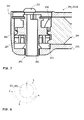
- FIG. 3 An exemplary profile of a groove or track 108 is shown in FIG. 3
- the receiving unit 106 or the track 108 have a plurality of sections 109-112 arranged at an angle to each other.
- the sections 109-112 form a substantially Y-shaped structure so that in the FIG. 3 three Y-shaped structures are visible, which are connected to each other at the ends of their arms.
- the receiving unit 106 or the track 108 for the eccentric pin 104 at least a first portion 109, 110, 111, which is shaped so that it causes a rotation of the output shaft 102 in a first rotational direction, in particular in the preferential or working direction
- the receiving unit 106 or the track 108 comprises at least one second portion 112, which is shaped such that it causes a rotation of the output shaft 102 in the second rotational direction, in particular in a preferred direction of substantially opposite direction or return direction.
- the second portion 112 preferably connects to at least one of the first portions 109-111, in particular to at least one end of a first portion 109-111, or the second portion 112 connects two first portions 109-111 together.
- the second portion 112 is preferably provided in a vertex area or vertically / axially (with respect to the second axis of rotation 2) outer area of the track 108.
- the second section 112 preferably has at least one partial section 112A, which is arranged substantially parallel to the second rotary axis 2 of the output shaft 102.
- the receiving unit 106 or the track 108 for the eccentric pin 104 at least one substantially parallel to the second axis of rotation 2 of the output shaft 102 disposed portion 110, of which in particular the first portion or arm 109 in a first direction and a second portion or Arm 111 in a second direction, which is different from the first direction, extend.
- the section 110 may be closed at its free end or at its end facing away from the sections 109, 111 (see FIG. 3 ) or it may be open and / or have an opening (see FIGS. 1, 2 ).
- the section 110 is preferably provided in a vertex area or lower area of the track 108, so that in particular the Sections 110 and 112 are provided on opposite vertical or axial (with respect to the second axis of rotation 2) end portions of the track 108.
- the first arm 109 has a first edge 109A and the second arm 111 has a second edge 111A, wherein the two edges 109A, 111A unite at a point of contact 113, and the point of contact 113 is parallel to the second axis of rotation 2 of the central axis 114 of FIG Output shaft 102 arranged portion 110 is spaced.
- the contact point 113 is arranged laterally from the central axis 114 or, viewed in the direction of a section 109, 111, as viewed from the central axis 114.
- a preferred direction of movement is predetermined in particular for the eccentric pin 104 or the eccentric gear 103.
- edges 109A, 111A and also each other edge or lower edge 109B, 111B delimit the sections or arms 109, 111, wherein the edges 109A, 111A in particular form the upper edges or those edges which are farther away from the section 110 than the Edges 109B, 111B.
- the angles between the sections 109, 110, 111 are preferably each greater than 90 °.
- the angle between the section 110 and the section 109 or 111 is in particular greater than 125 °, the angle between the section 109 and the section 111 is in particular about 95 ° - 110 °.
- the drive device 200 or the eccentric gear 203 have a plurality, for example two, eccentric pins 204, 205.
- the first eccentric pin 204 and the second eccentric pin 205 are at different distances from the first axis of rotation 1 of the drive shaft 201.
- the eccentric pins 204, 205 lie on a common straight line which extends at right angles from or intersects the first axis of rotation 1.
- the receiving units 206, 207 each comprise a circular plate or disk, on whose outer or peripheral surface in each case a plurality of grooves 209, 201 are provided.
- the receiving units 206, 207 surround the output shaft 202, in particular circular, and / or they are arranged concentrically to the second axis of rotation 2.
- the first receiving unit 206 and the second receiving unit 207 are separated from each other by a recess 211.
- the first grooves 209 and the second grooves 210 are arranged offset from one another in such a way that alternately a first groove 209 and a second groove 210 is provided.
- the grooves 209, 210 extend along the second axis of rotation 2 and / or substantially parallel to the second axis of rotation 2.
- at least the bottoms of some grooves 209, 210 are inclined in the direction of the second axis of rotation 2.
- the first grooves 209 and the second grooves 210 surround the second rotation axis 2 in a circular arrangement.
- the eccentric gear 203 is designed in such a way that during operation, the first eccentric pin 204 alternately engages in the first receiving unit 206 and the second eccentric pin 205 engages in the second receiving unit 207.
- the eccentric gear 203 is designed such that it engages in operation when an eccentric pin 204, 205 in its associated receiving unit 206, 207 such that it causes rotation of the output shaft 202, the other eccentric pin 204, 205 occupies a position in which it does not cause rotation of the output shaft 202.
- the invention is not limited to the described embodiments, but includes all embodiments that apply or include the principle, analogous principle of operation of the invention. Furthermore, all features of all described and illustrated embodiments can be combined.
Abstract
Antriebsvorrichtung (100; 200) für ein medizinisches Werkzeug, die ausgebildet ist, das Werkzeug in eine oszillierende Rotationsbewegung zu versetzen, wobei die oszillierende Rotationsbewegung eine abwechselnde Rotation des Werkzeugs in eine erste Drehrichtung und in eine zweite Drehrichtung umfasst, derart dass das Werkzeug bei mehrfachem, sequentiellen Rotieren in die erste und in die zweite Drehrichtung in Summe eine Rotationsbewegung in eine Vorzugsrichtung erfährt, wobei die Antriebsvorrichtung (100; 200) umfasst: Eine um eine erste Drehachse (1) rotierende Antriebswelle (101; 201), die zur Übertragung einer unidirektionalen Rotationsbewegung ausgebildet ist, eine in die oszillierende Rotationsbewegung versetzbare und um eine zweite Drehachse (2) rotierbare Abtriebswelle (102; 202) und ein Exzentergetriebe (103; 203), das die Antriebswelle (101; 201) und die Abtriebswelle (102; 202) verbindet, wobei das Exzentergetriebe (103; 203) zumindest einen Exzenterstift (104; 204, 205) und zumindest eine Aufnahmeeinheit (106; 206, 207) für den Exzenterstift (104; 204, 205) umfasst.A medical tool driving apparatus (100; 200) adapted to set the tool in an oscillating rotational motion, wherein the oscillating rotational movement comprises alternating rotation of the tool in a first rotational direction and in a second rotational direction such that the tool is rotated multiple times , sequentially rotating in the first and in the second rotational direction in total undergoes a rotational movement in a preferred direction, wherein the drive device (100, 200) comprises: about a first axis of rotation (1) rotating drive shaft (101, 201), for transmitting a an unidirectional rotational movement is formed, an oscillatory rotational movement displaceable and about a second axis of rotation (2) rotatable output shaft (102; 202) and an eccentric (103; 203), the drive shaft (101; 201) and the output shaft (102; 202 ), wherein the eccentric gear (103, 203) at least one eccentric pin (104; 204, 205) u at least one receiving unit (106; 206, 207) for the eccentric pin (104, 204, 205).
Description
Die vorliegende Erfindung betrifft eine mechanische Antriebsvorrichtung für ein medizinisches, insbesondere dentales oder chirurgisches, Werkzeug, die ausgebildet ist, das Werkzeug in eine oszillierende Rotationsbewegung zu versetzen. Als oszillierende Rotationsbewegung wird dabei eine Rotationsbewegung verstanden, bei der das Werkzeug abwechselnde in eine erste Drehrichtung um einen ersten Drehwinkel und in eine zweite Drehrichtung, welche der ersten Drehrichtung im Wesentlichen entgegengesetzt ist, um einen zweiten Drehwinkel rotiert, wobei der erste und der zweite Drehwinkel unterschiedliche Beträge aufweisen, so dass das Werkzeug bei mehrfachem, sequentiellen Rotieren in die erste und in die zweite Drehrichtung in Summe eine Rotationsbewegung in eine Vorzugsrichtung erfährt.The present invention relates to a mechanical drive device for a medical, in particular dental or surgical, tool, which is adapted to set the tool in an oscillating rotational movement. The oscillating rotational movement is understood to mean a rotational movement in which the tool alternately rotates in a first rotational direction by a first rotational angle and in a second rotational direction, which is substantially opposite to the first rotational direction, by a second rotational angle, wherein the first and the second rotational angle have different amounts, so that the tool in multiple, sequential rotation in the first and in the second rotational direction in total undergoes a rotational movement in a preferred direction.
Eine derartige mechanische Antriebsvorrichtung ist aus der Patentanmeldung
Ziel der vorliegenden Erfindung ist es, eine alternative mechanische Antriebsvorrichtung zu schaffen, die ausgebildet ist, ein medizinisches, insbesondere dentales oder chirurgisches, Werkzeug in eine oszillierende Rotationsbewegung zu versetzen, wobei diese alternative mechanische Antriebsvorrichtung im Vergleich zu der aus dem Stand der Technik bekannten Antriebsvorrichtung vorzugsweise zumindest einen der folgenden Vorteile aufweisen sollen: Sie soll einfacher aufgebaut oder herstellbar sein; sie soll weniger Bauteile aufweisen; sie soll kostengünstiger herstellbar sein; sie soll kleiner sein.The aim of the present invention is to provide an alternative mechanical drive device which is adapted to set a medical, in particular dental or surgical tool in an oscillating rotational movement, said alternative mechanical drive device compared to the drive device known from the prior art preferably should have at least one of the following advantages: It should be simpler in design or manufacture; it should have fewer components; it should be cheaper to produce; she should be smaller.
Diese Aufgabe wird gemäß der vorliegenden Erfindung durch eine (mechanische) Antriebsvorrichtung für ein medizinisches, insbesondere dentales oder chirurgisches, Werkzeug, gelöst, die ausgebildet ist, das Werkzeug in eine oszillierende Rotationsbewegung zu versetzen, wobei die oszillierende Rotationsbewegung eine abwechselnde Rotation des Werkzeugs in eine erste Drehrichtung um einen ersten Drehwinkel und in eine zweite Drehrichtung, welche der ersten Drehrichtung im Wesentlichen entgegengesetzt ist, um einen zweiten Drehwinkel umfasst, wobei der erste und der zweite Drehwinkel unterschiedliche Beträge aufweisen, so dass das Werkzeug bei mehrfachem, sequentiellen Rotieren in die erste und in die zweite Drehrichtung in Summe eine Rotationsbewegung in eine Vorzugsrichtung erfährt, wobei die Antriebsvorrichtung umfasst: Eine um eine erste Drehachse rotierende Antriebswelle, die zur Übertragung einer unidirektionalen Rotationsbewegung ausgebildet ist, eine in die oszillierende Rotationsbewegung versetzbare und um eine zweite Drehachse rotierbare Abtriebswelle und ein Exzentergetriebe, das die Antriebswelle und die Abtriebswelle verbindet, wobei das Exzentergetriebe zumindest einen Exzenterstift und zumindest eine Aufnahmeeinheit für den Exzenterstift umfasst, die derart zusammenwirken oder ausgebildet sind, dass die Abtriebswelle und ein mit der Abtriebswelle verbindbares Werkzeug in die oszillierende Rotationsbewegung versetzbar sind.This object is achieved according to the present invention by a (mechanical) driving device for a medical, in particular dental or surgical, tool, which is adapted to set the tool in an oscillating rotational movement, wherein the oscillating rotational movement of an alternating rotation of the tool in a first rotational direction by a first rotational angle and in a second rotational direction which is substantially opposite to the first rotational direction, by a second rotational angle, wherein the first and the second rotational angle have different amounts, so that the tool at multiple, sequential rotation in the first and in the second rotational direction in total undergoes rotational movement in a preferred direction, wherein the drive device comprises: a drive shaft rotating about a first axis of rotation, which is designed to transmit a unidirectional rotational movement, one in the oscillating rotational movement displaceable and rotatable about a second axis of rotation output shaft and an eccentric, which connects the drive shaft and the output shaft, wherein the eccentric comprises at least one eccentric pin and at least one receiving unit for the eccentric pin, which cooperate or are formed such that the output shaft and a connectable to the output shaft tool are displaceable in the oscillating rotational movement.
Wie im Nachfolgenden noch im Detail dargestellt, ist somit nur ein Getriebe, insbesondere nur ein Exzentergetriebe, vorgesehen oder benötigt, um die von der Antriebswelle zur Verfügung gestellte unidirektionalen Rotationsbewegung in die oszillierende Rotationsbewegung zu wandeln. Vorzugsweise ist das Exzentergetriebe ausgebildet, insbesondere alleine oder ohne einem weiteren Getriebe, die von der Antriebswelle zur Verfügung gestellte unidirektionalen Rotationsbewegung in die oszillierende Rotationsbewegung zu wandeln und diese insbesondere auf die Abtriebswelle zu übertragen. Diese Ausbildung des Exzentergetriebes ist im Vergleich zu der aus dem Stand der Technik bekannten Getriebeeinheit, bei der neben dem nur eine Pendelbewegung erzeugenden Exzentergetriebe ein zweites Getriebe benötigt wird, um die oszillierende Rotationsbewegung zu erzeugen, von erheblichem Vorteil, insbesondere in Bezug auf einen einfachen und platzsparenden Aufbau und eine kostengünstige Herstellung.As will be shown in detail below, therefore, only one gear, in particular only one eccentric gear, is provided or required in order to convert the unidirectional rotational movement provided by the drive shaft into the oscillating rotational movement. Preferably, the eccentric gear is formed, in particular alone or without another gear, to convert the unidirectional rotational movement provided by the drive shaft into the oscillating rotational movement and in particular to transmit this to the output shaft. This design of the eccentric gear is in comparison to the known from the prior art gear unit, in which in addition to only one oscillating eccentric gear generating a second gear is required to produce the oscillating rotational movement, of considerable advantage, in particular with respect to a simple and space-saving design and cost-effective production.
Das Exzentergetriebe ist vorzugsweise durch zumindest ein an der Antriebswelle und / oder an der Abtriebswelle vorgesehenes Lager, insbesondere ein Wälzlager oder Kugellager, gelagert. Das Exzentergetriebe ist vorzugsweise aus Metall und / oder Kunststoff gebildet. Das Exzentergetriebe ist vorzugsweise von der ersten Drehachse der Antriebswelle und / oder von der zweiten Drehachse der Abtriebswelle durchsetzt.The eccentric gear is preferably mounted by at least one bearing provided on the drive shaft and / or on the output shaft, in particular a roller bearing or ball bearing. The eccentric gear is preferably formed of metal and / or plastic. The eccentric gear is preferably penetrated by the first axis of rotation of the drive shaft and / or by the second axis of rotation of the output shaft.
Vorzugsweise ist die Aufnahmeeinheit für den Exzenterstift auf einer die erste Drehachse oder die zweite Drehachse umgebenden, im Wesentlichen zylindrischen Oberfläche vorgesehen. Vorzugsweise umfasst die Aufnahmeeinheit zumindest eine Vertiefung, zumindest einen Einstich oder zumindest eine Nut. Besonders bevorzugt weist die Aufnahmeeinheit für den Exzenterstift eine geschlossene (endlose), die erste Drehachse oder die zweite Drehachse umgebende, Bahn oder Führung auf oder die Aufnahmeeinheit bildet eine derartige geschlossene (endlose), die erste Drehachse oder die zweite Drehachse umgebende, Bahn oder Führung. Besonders bevorzugt erstreckt sich die Aufnahmeeinheit, insbesondere die Bahn oder Führung, im Wesentlichen wellenförmig oder geschwungen um die erste Drehachse oder die zweite Drehachse, insbesondere auf der die erste Drehachse oder die zweite Drehachse umgebenden, im Wesentlichen zylindrischen Oberfläche. Vorzugsweise weist die Aufnahmeeinheit zumindest einen Abschnitt oder eine Nut auf, die sich im Wesentlichen axial in Bezug auf die zweite Drehachse der Abtriebswelle erstreckt. Vorzugsweise weist die Aufnahmeeinheit, insbesondere die Nut, die sich im Wesentlichen axial in Bezug auf die zweite Drehachse der Abtriebswelle erstreckt, eine Bodenfläche auf, die zumindest in einem Abschnitt in Richtung der zweiten Drehachse der Abtriebswelle geneigt ist, so dass bevorzugt zumindest in einem Abschnitt die Aufnahmeeinheit oder die Nut eine sich verändernde Tiefe aufweist, insbesondere in Bezug auf eine im Wesentlichen zylindrischen Oberfläche oder Mantelfläche, in der die Aufnahmeeinheit oder die Nut aufgenommen ist.Preferably, the receiving unit for the eccentric pin is provided on a substantially cylindrical surface surrounding the first axis of rotation or the second axis of rotation. Preferably, the receiving unit comprises at least one recess, at least one recess or at least one groove. Particularly preferably, the receiving unit for the eccentric pin on a closed (endless), the first axis of rotation or the second axis of rotation surrounding, web or guide or the receiving unit forms such a closed (endless), the first axis of rotation or the second axis of rotation surrounding, web or guide , Particularly preferably, the extends Receiving unit, in particular the track or guide, substantially wave-shaped or curved about the first axis of rotation or the second axis of rotation, in particular on the first axis of rotation or the second axis of rotation surrounding, substantially cylindrical surface. Preferably, the receiving unit has at least a portion or a groove which extends substantially axially with respect to the second axis of rotation of the output shaft. Preferably, the receiving unit, in particular the groove, which extends substantially axially with respect to the second axis of rotation of the output shaft, a bottom surface which is inclined at least in a portion in the direction of the second axis of rotation of the output shaft, so preferably at least in one section the receiving unit or the groove has a varying depth, in particular with respect to a substantially cylindrical surface or lateral surface, in which the receiving unit or the groove is received.
Gemäß einem Ausführungsbeispiel weist die Aufnahmeeinheit oder Bahn für den Exzenterstift mehrere gewinkelt zueinander angeordnete Abschnitte auf. Vorzugsweise weist die Aufnahmeeinheit mehrere im Wesentlichen Y-förmige Abschnitte auf, die miteinander verbunden sind, insbesondere an den Seitenarmen des Y miteinander verbunden sind. Vorzugsweise sind die Seitenarme des Y etwas versetzt zueinander und / oder in Bezug auf den vertikalen oder dritten Arm des Y angeordnet.According to one embodiment, the receiving unit or track for the eccentric pin on several mutually angularly arranged sections. Preferably, the receiving unit has a plurality of substantially Y-shaped portions, which are connected to each other, in particular on the side arms of the Y are connected to each other. Preferably, the side arms of the Y are slightly offset from each other and / or arranged with respect to the vertical or third arm of the Y.
Bevorzugt weist die Aufnahmeeinheit für den Exzenterstift zumindest einen ersten Abschnitt, der derart geformt ist, dass er eine Drehung der Abtriebswelle in die erste Drehrichtung bewirkt, und einen zweiten Abschnitt, der derart geformt ist, dass er eine Drehung der Abtriebswelle in die zweite Drehrichtung bewirkt, auf. Besonders bevorzugt umfasst der erste Abschnitt, der derart geformt ist, dass er eine Drehung der Abtriebswelle in die erste Drehrichtung bewirkt, mehrere geneigt oder gewinkelt zueinander angeordnete Unterabschnitte auf. Vorzugsweise weisen der erste Abschnitt und der zweite Abschnitt unterschiedliche Längen auf. Insbesondere weist jener Abschnitt, der eine Rotationsbewegung der Abtriebswelle in die Vorzugsrichtung bewirkt, eine größere Länge auf als jener Abschnitt, der eine Rotationsbewegung der Abtriebswelle entgegen der Vorzugsrichtung bewirkt. Vorzugsweise ist jener Abschnitt, der eine Rotationsbewegung der Abtriebswelle entgegen der Vorzugsrichtung bewirkt, an einem Ende zumindest eines Seitenarms eines Y-förmigen Abschnitts der Aufnahmeeinheit angeordnet.Preferably, the receiving unit for the eccentric pin has at least a first portion shaped to cause the output shaft to rotate in the first rotational direction and a second portion shaped to cause the output shaft to rotate in the second rotational direction , on. Particularly preferably, the first portion, which is shaped such that it causes a rotation of the output shaft in the first direction of rotation, a plurality of inclined or angled mutually arranged subsections. Preferably, the first portion and the second portion have different lengths. In particular, that portion which causes a rotational movement of the output shaft in the preferred direction, a greater length than that portion which causes a rotational movement of the output shaft against the preferred direction. Preferably, that portion which causes a rotational movement of the output shaft against the preferential direction, arranged at one end of at least one side arm of a Y-shaped portion of the receiving unit.
Bevorzugt weist die Aufnahmeeinheit für den Exzenterstift, insbesondere die Nut, zumindest einen im Wesentlichen parallel zur zweiten Drehachse der Abtriebswelle angeordneten Abschnitt auf, wobei dieser Abschnitt insbesondere dem im Vorstehenden beschriebenen vertikalen Arm des Y-förmigen Abschnitts der Aufnahmeeinheit entspricht. Insbesondere erstrecken sich von diesem parallel zur zweiten Drehachse der Abtriebswelle angeordneten Abschnitt ein erster Arm in eine erste Richtung und ein zweiter Arm in eine zweite Richtung, die von der ersten Richtung unterschiedlich ist. Der Winkel zwischen diesen beiden Armen oder den Seitenarmen des Y ist vorzugsweise größer 90°.Preferably, the receiving unit for the eccentric pin, in particular the groove, at least one arranged substantially parallel to the second axis of rotation of the output shaft portion, this portion corresponds in particular to the above-described vertical arm of the Y-shaped portion of the receiving unit. In particular, a first arm extends in a first direction and a second arm in a second direction, which is different from the first direction, from this section arranged parallel to the second axis of rotation of the output shaft. The angle between these two arms or the side arms of the Y is preferably greater than 90 °.
Besonders bevorzugt weisen der erste Arm eine erste Kante und der zweite Arm eine zweite Kante auf, wobei die beiden Kanten sich in einem Kontaktpunkt vereinigen, wobei der Kontaktpunkt von einer Mittelachse des parallel zur zweiten Drehachse der Abtriebswelle angeordneten Abschnitts beabstandet oder horizontal verschoben ist oder außerhalb des parallel zur zweiten Drehachse der Abtriebswelle angeordneten Abschnitts angeordnet ist. Durch diese Anordnung des Kontaktpunkts wird die Drehung des Exzenterstifts oder des Exzentergetriebes in eine Vorzugsrichtung definiert oder es wird die Drehung des Exzenterstifts oder des Exzentergetriebes in eine Richtung, insbesondere in eine der Vorzugsrichtung entgegengesetzte Richtung, verhindert oder erschwert. Die beiden Kanten der Arme begrenzen vorzugsweise die Arme, insbesondere definieren die Kanten die obere Grenze der Arme oder Nuten. Insbesondere weisen die beiden Arme jeweils eine weitere Kante auf, welche die untere Grenze der Arme oder Nuten definiert. Vorzugsweise gehen die Unterkanten in den im Wesentlichen parallel zur zweiten Drehachse der Abtriebswelle angeordneten Abschnitt oder in den vertikalen Arm des Y-förmigen Abschnitts der Aufnahmeeinheit über.Particularly preferably, the first arm on a first edge and the second arm on a second edge, wherein the two edges unite in a contact point, wherein the contact point from a central axis of the arranged parallel to the second axis of rotation of the output shaft portion is spaced or horizontally displaced or outside of the arranged parallel to the second axis of rotation of the output shaft portion is arranged. As a result of this arrangement of the contact point, the rotation of the eccentric pin or of the eccentric gear is defined in a preferred direction or the rotation of the eccentric pin or the eccentric gear in one direction, in particular in a direction opposite to the preferred direction, is prevented or impeded. The two edges of the arms preferably define the arms, in particular the edges define the upper limit of the arms or grooves. In particular, the two arms each have a further edge defining the lower limit of the arms or grooves. Preferably, the lower edges go over in the arranged substantially parallel to the second axis of rotation of the output shaft portion or in the vertical arm of the Y-shaped portion of the receiving unit.
Gemäß diesem Ausführungsbeispiel ist das Exzentergetriebe derart ausgebildet, dass der Exzenterstift sich in der Nut oder Führung oder Bahn der Aufnahmeeinheit bewegt, wobei aufgrund der im Vorstehenden beschriebenen Ausgestaltung oder Form der Nut oder Führung oder Bahn die, insbesondere mit der Aufnahmeeinheit direkt oder einteilig verbundene, Abtriebswelle in eine oszillierende Rotationsbewegung versetzbar ist.According to this embodiment, the eccentric gear is designed such that the eccentric pin moves in the groove or guide or track of the receiving unit, wherein due to the above-described configuration or shape of the groove or guide or track which, in particular directly or integrally connected to the receiving unit, Output shaft is displaceable in an oscillating rotational movement.
Gemäß einem alternativen Ausführungsbeispiel umfasst das Exzentergetriebe einen ersten Exzenterstift, dem eine erste Aufnahmeeinheit zugeordnet ist, und einen zweiten Exzenterstift, dem eine zweite Aufnahmeeinheit zugeordnet ist. Vorzugsweise ist dieses Exzentergetriebe derart ausgebildet, dass ein Exzenterstift und die ihm zugeordnete Aufnahmeeinheit die Abtriebswelle in eine erste Richtung, zum Beispiel in eine Vorzugsrichtung bewegt, und dass der andere Exzenterstift und die ihm zugeordnete Aufnahmeeinheit die Abtriebswelle in eine zweite, der ersten Richtung oder Vorzugsrichtung im Wesentlichen entgegengesetzte Richtung bewegt. Vorzugsweise ist das Exzentergetriebe derart ausgebildet, dass die Drehwinkel, welche die beiden Aufnahmeeinheiten erzeugen, unterschiedliche Beträge aufweisen, so dass in Summe die Abtriebswelle in eine oszillierende Rotationsbewegung versetzbar ist.According to an alternative embodiment, the eccentric gear comprises a first eccentric pin, which is associated with a first receiving unit, and a second eccentric pin, which is associated with a second receiving unit. Preferably, this eccentric gear is designed such that an eccentric pin and its associated receiving unit moves the output shaft in a first direction, for example in a preferred direction, and that the other eccentric pin and its associated receiving unit, the output shaft in a second, the first direction or preferred direction moved in the opposite direction. Preferably, the eccentric gear is designed such that the rotational angles which generate the two receiving units, have different amounts, so that in sum, the output shaft is displaceable in an oscillating rotational movement.
Vorzugsweise sind der erste Exzenterstift und der zweite Exzenterstift unterschiedlich weit von der ersten Drehachse der Antriebswelle beabstandet. Vorzugsweise weist die Antriebswelle eine der Abtriebswelle zugewandte Endfläche auf, wobei ein Exzenterstift an oder nahe dem Außenumfang dieser Endfläche angeordnet ist. Vorzugsweise sind die beiden Exzenterstifte auf einer gemeinsamen Geraden vorgesehen, wobei die Gerade im Wesentlichen rechtwinkelig zur ersten Drehachse der Antriebswelle angeordnet ist.Preferably, the first eccentric pin and the second eccentric pin are at different distances from the first axis of rotation of the drive shaft. The drive shaft preferably has an end face facing the output shaft, wherein an eccentric pin is arranged on or near the outer circumference of this end face. Preferably, the two eccentric pins are provided on a common straight line, wherein the straight line is arranged substantially perpendicular to the first axis of rotation of the drive shaft.
Vorzugsweise sind die erste Aufnahmeeinheit und die zweite Aufnahmeeinheit voneinander beabstandet, insbesondere bezogen auf die zweite Drehachse der Abtriebswelle axial voneinander entfernt. Vorzugsweise sind die erste Aufnahmeeinheit und die zweite Aufnahmeeinheit, zum Beispiel durch einen Einstich, voneinander getrennt.Preferably, the first receiving unit and the second receiving unit are spaced apart, in particular with respect to the second axis of rotation of the output shaft axially away from each other. Preferably, the first receiving unit and the second receiving unit, for example, by a puncture, separated from each other.
Vorzugsweise weist die erste Aufnahmeeinheit mehrere erste Nuten und die zweite Aufnahmeeinheit mehrere zweite Nuten auf. Vorzugsweise sind die ersten und / oder zweiten Nuten im Wesentlichen parallel zur zweiten Drehachse der Abtriebswelle angeordnet. Vorzugsweise sind die ersten Nuten und die zweiten Nuten derart versetzt zueinander angeordnet, dass abwechselnd eine erste Nut und eine zweite Nut vorgesehen ist.Preferably, the first receiving unit has a plurality of first grooves and the second receiving unit a plurality of second grooves. Preferably, the first and / or second grooves are arranged substantially parallel to the second axis of rotation of the output shaft. Preferably, the first grooves and the second grooves are arranged offset from one another in such a way that alternately a first groove and a second groove is provided.
Vorzugsweise umgeben die erste Aufnahmeeinheit und die zweite Aufnahmeeinheit die zweite Drehachse der Abtriebswelle im Wesentlichen kreisförmig. Besonders bevorzugt ist / sind die erste Aufnahmeeinheit und / oder die zweite Aufnahmeeinheit als scheiben-oder plattenförmige Elemente ausgebildet, durch deren Mitte sich die Abtriebswelle erstreckt. Besonders bevorzugt ist / sind die erste Aufnahmeeinheit und / oder die zweite Aufnahmeeinheit als scheiben- oder plattenförmige Elemente ausgebildet, an deren Außenumfang oder Außenmantel die ersten und zweiten Nuten vorgesehen sind. Besonders bevorzugt ist zumindest eine Aufnahmeeinheit einteilig mit der Abtriebswelle ausgebildet oder hergestellt.Preferably, the first receiving unit and the second receiving unit surround the second axis of rotation of the output shaft substantially circular. Particularly preferably, the first receiving unit and / or the second receiving unit are / is formed as disk-shaped or plate-shaped elements, through the center of which the output shaft extends. Particularly preferably, the first receiving unit and / or the second receiving unit are / is designed as disk-shaped or plate-shaped elements, on whose outer circumference or outer jacket the first and second grooves are provided. Particularly preferably, at least one receiving unit is formed or manufactured in one piece with the output shaft.
Vorzugsweise umgeben die ersten Nuten der ersten Aufnahmeeinheit und die zweiten Nuten der zweiten Aufnahmeeinheit die zweite Drehachse und / oder die Abtriebswelle in einer kreisförmigen Anordnung. Vorzugsweise sind die Nuten einer Aufnahmeeinheit gleichmäßig um den Umfang der Aufnahmeeinheit und / oder um die zweite Drehachse der Abtriebswelle angeordnet und / oder gleichmäßig voneinander beabstandet.Preferably, the first grooves of the first receiving unit and the second grooves of the second receiving unit surround the second axis of rotation and / or the output shaft in a circular arrangement. Preferably, the grooves of a receiving unit are arranged uniformly around the circumference of the receiving unit and / or about the second axis of rotation of the output shaft and / or evenly spaced from each other.
Vorzugsweise ist das Exzentergetriebe derart ausgebildet, dass abwechselnd oder nicht gleichzeitig der erste Exzenterstift in die erste Aufnahmeeinheit und der zweite Exzenterstift in die zweite Aufnahmeeinheit eingreift. Alternativ und / oder zusätzlich ist das Exzentergetriebe derart ausgebildet, dass während ein Exzenterstift derart in die ihm zugeordnete Aufnahmeeinheit eingreift, dass er eine Drehung der Abtriebswelle bewirkt, der andere Exzenterstift eine Position einnimmt, in der er keine Drehung der Abtriebswelle bewirkt.Preferably, the eccentric gear is designed such that alternately or not simultaneously engages the first eccentric pin in the first receiving unit and the second eccentric pin in the second receiving unit. Alternatively and / or additionally, the eccentric gear is designed such that while an eccentric pin engages in its associated receiving unit such that it causes a rotation of the output shaft, the other eccentric pin assumes a position in which it does not cause rotation of the output shaft.
Bevorzugt ist eine medizinische, insbesondere dentale oder chirurgische, Behandlungsvorrichtung, vorzugsweise ein medizinisches, insbesondere dentales oder chirurgisches, Handgriffelement, welche(s) insbesondere für endodontische Behandlungen ausgebildet ist, mit einer Antriebsvorrichtung versehen, die ein Exzentergetriebe aufweist, das ausgebildet ist, insbesondere alleine oder ohne einem weiteren Getriebe, die von der Antriebswelle zur Verfügung gestellte unidirektionalen Rotationsbewegung in eine oszillierende Rotationsbewegung zu wandeln und diese insbesondere auf die Abtriebswelle zu übertragen. Besonders bevorzugt ist die Antriebsvorrichtung derart in der Behandlungsvorrichtung oder in dem Handgriffelement angeordnet, dass die erste Drehachse der Antriebswelle und die zweite Drehachse der Abtriebswelle gewinkelt zueinander angeordnet sind, wobei der Winkel größer 0° ist und insbesondere zwischen 90° und 100° beträgt.Preferably, a medical, in particular dental or surgical, treatment device, preferably a medical, in particular dental or surgical, handle element, which (s) is in particular designed for endodontic treatments, provided with a drive device having an eccentric, which is formed, in particular alone or without a further gear, to convert the unidirectional rotational movement provided by the drive shaft into an oscillating rotational movement and to transmit this in particular to the output shaft. Particularly preferably, the drive device is arranged in the treatment device or in the handle element, that the first axis of rotation of the drive shaft and the second axis of rotation of the output shaft are arranged angled to each other, wherein the angle is greater than 0 ° and in particular between 90 ° and 100 °.
Vorzugsweise umfassen die Behandlungsvorrichtung oder das Handgriffelement einen Kopfabschnitt mit einer Werkzeughaltevorrichtung für das Werkzeug, wobei zumindest ein Teil der Werkzeughaltevorrichtung in der Abtriebswelle angeordnet ist. Besonders bevorzugt schließt an den Kopfabschnitt ein Griffabschnitt an, wobei das Exzentergetriebe zumindest teilweise in dem Kopfabschnitt und / oder in dem Griffabschnitt und / oder in einem Verbindungsbereich des Kopfabschnitts mit dem Griffabschnitt angeordnet ist.Preferably, the treatment device or the handle element comprise a head portion with a tool holding device for the tool, wherein at least a part of the tool holding device is arranged in the output shaft. Particularly preferably, a grip section adjoins the head section, wherein the eccentric gear is arranged at least partially in the head section and / or in the grip section and / or in a connection region of the head section with the grip section.
Die Erfindung wird nachfolgend anhand bevorzugter Ausführungsbeispiele und Bezug nehmend auf die beigefügten Zeichnungen erläutert. Es zeigt die
-
Figur 1 -
Figur 2Figur 1 -
Figur 3Figur 1 -
Figur 4Figur 1 -
Figur 5 ein zweites Ausführungsbeispiel einer Antriebsvorrichtung oder eines Exzentergetriebes, die / das ausgebildet ist, das Werkzeug in eine oszillierende Rotationsbewegung zu versetzen, wobei zwecks Klarheit die beiden Hauptkomponenten voneinander getrennt sind. -
Figur 6 die Antriebsvorrichtung oder das Exzentergetriebe derFigur 5 in zusammengesetztem, betriebsbereitem Zustand. -
Figur 7 eine medizinische, insbesondere dentale oder chirurgische, Behandlungsvorrichtung oder ein medizinisches, insbesondere dentales oder chirurgisches, Handgriffelement mit einer Antriebsvorrichtung oder einem Exzentergetriebe derFigur 5 . -
Figur 8 zeigt schematisch ein Beispiel einer oszillierenden Rotationsbewegung, wie sie durch eine Antriebsvorrichtung, die eine unidirektionale Rotationsbewegung in eine oszillierende Rotationsbewegung wandelt, erzeugbar ist.
-
FIG. 1 a first embodiment of a drive device or an eccentric, which is adapted to set the tool in an oscillating rotational movement, wherein for clarity, the two main components are separated from each other. -
FIG. 2 the drive device or the eccentric gear ofFIG. 1 in assembled, ready-to-use condition. -
FIG. 3 an embodiment of a receiving unit or track for the eccentric pin of the drive device or the eccentric of theFIG. 1 in a two-dimensional representation. -
FIG. 4 a medical, in particular dental or surgical treatment device or a medical, in particular dental or surgical, handle element with a drive device or an eccentric gear ofFIG. 1 , -
FIG. 5 a second embodiment of a drive device or an eccentric gear, which is adapted to set the tool in an oscillating rotational movement, wherein for clarity, the two main components are separated from each other. -
FIG. 6 the drive device or the eccentric gear ofFIG. 5 in assembled, ready-to-use condition. -
FIG. 7 a medical, in particular dental or surgical treatment device or a medical, in particular dental or surgical, handle element with a drive device or an eccentric gear ofFIG. 5 , -
FIG. 8 shows schematically an example of an oscillating rotational movement, as can be generated by a drive device that converts a unidirectional rotational movement in an oscillating rotational motion.
Die in den
Die Antriebsvorrichtungen 100; 200 umfassen eine um eine erste Drehachse 1 rotierende Antriebswelle 101; 201, die zur Übertragung einer unidirektionalen Rotationsbewegung ausgebildet ist, eine in die oszillierende Rotationsbewegung versetzbare und um eine zweite Drehachse 2 rotierbare Abtriebswelle 102; 202 und ein Exzentergetriebe 103; 203, das die Antriebswelle 101; 201 und die Abtriebswelle 102; 202 verbindet. Die Antriebswelle 101; 201 ist mit einer Antriebseinheit verbindbar oder verbunden, zum Beispiel einem Motor, insbesondere einem Elektromotor. Die Antriebswelle 101; 201 ist vorzugsweise durch ein Lager 115 drehbar gelagert, insbesondere in einer Behandlungsvorrichtung 150; 250 oder einem Handgriffelement 150A; 250A.The
Das Exzentergetriebe 103; 203 umfasst zumindest einen Exzenterstift 104; 204, 205 und zumindest eine Aufnahmeeinheit 106; 206, 207 für den Exzenterstift 104; 204, 205, die derart zusammenwirken, dass die Abtriebswelle 102; 202 und ein mit der Abtriebswelle 102; 202 verbindbares Werkzeug in eine oszillierende Rotationsbewegung versetzbar sind.The
Der zumindest eine Exzenterstift 104; 204, 205 ist an einer Endfläche 116; 216 der Antriebswelle 101; 201 vorgesehen, wobei die Endfläche 116; 216 insbesondere der Abtriebswelle 102; 202 zugewandt ist. Vorzugsweise ist der zumindest eine Exzenterstift 104; 204, 205 an oder nahe dem Außenrand der Endfläche 116; 216 angeordnet. Vorzugsweise hat die Endfläche 116; 216 einen größeren Außendurchmesser als die Antriebswelle 101; 201.The at least one
Die Aufnahmeeinheit 106; 206, 207 und / oder zumindest eine darauf vorgesehene Bahn 108 oder Nut 209, 210 umgeben die Abtriebswelle 102; 202 kreisförmig oder sind im Wesentlichen konzentrisch zur zweiten Drehachse 2 angeordnet. Die Aufnahmeeinheit 106; 206, 207 ist vorzugsweise einteilig mit der Abtriebswelle 102; 202 ausgebildet.The receiving
Die Abtriebswelle 102; 202 ist vorzugsweise als Hohlwelle ausgebildet, in der zumindest ein Teil des Werkzeugs und / oder zumindest ein Teil einer Werkzeughaltevorrichtung 152; 252 aufnehmbar oder aufgenommen ist. Die Abtriebswelle 102; 202 und die mit ihr drehfest verbundenen Bauteile, zum Beispiel die Aufnahmeeinheit 106; 206, 207 oder die Werkzeughaltevorrichtung 152; 252, sind mittels zumindest einem Lager beweglich oder drehbar in einem Kopfabschnitt 151; 251 der Behandlungsvorrichtung 150; 250 oder des Handgriffelements 150A; 250A aufgenommen.The
Die von der Antriebsvorrichtung 100; 200 oder dem Exzentergetriebe 103; 203 erzeugte und auf die Abtriebswelle 102; 202 und / oder ein damit verbundenes Werkzeug übertragene oszillierende Rotationsbewegung ist in der
Die Frequenz der Oszillationsbewegung der Abtriebswelle 102; 202 oder des Werkzeugs liegt zum Beispiel im Bereich von etwa 3 - 50 Hertz, vorzugsweise im Bereich von etwa 5 - 20 Hertz, insbesondere bei etwa 10 Hertz.The frequency of the oscillation movement of the
Die
Im Folgenden werden weitere Merkmale der Antriebsvorrichtung 100 beschrieben (siehe
Die Aufnahmeeinheit 106 ist insbesondere durch einen zylindrischen Körper 106A gebildet, in dem eine geschlossene Bahn oder Führung 108 für den Exzenterstift 104 vorgesehen ist. Die geschlossene Bahn oder Führung 108 ist insbesondere an der Außen-oder Mantelfläche des zylindrischen Körpers 106A vorgesehen. Der zylindrische Körper 106A wird mittig oder entlang seiner Längsachse 2 von der Abtriebswelle 102 durchsetzt.The receiving
Die Bahn oder Führung 108 ist insbesondere derart in sich geschlossen, dass sie einen gewellten oder axial (in Bezug auf die zweite Drehachse 2) auf- und absteigenden Kreis bildet, in dessen Mitte die zweite Drehachse 2 und / oder die Abtriebswelle 102 angeordnet sind.The track or guide 108 is closed in particular in such a way that it forms a corrugated or axially (with respect to the second axis of rotation 2) ascending and descending circle in the middle of the second axis of
Ein beispielhafter Verlauf einer Nut oder Bahn 108 ist in der
Vorzugsweise weist die Aufnahmeeinheit 106 oder die Bahn 108 für den Exzenterstift 104 zumindest einen ersten Abschnitt 109, 110, 111 auf, der derart geformt ist, dass er eine Drehung der Abtriebswelle 102 in eine erste Drehrichtung, insbesondere in die Vorzugs-oder Arbeitsrichtung, bewirkt. Des Weiteren umfasst die Aufnahmeeinheit 106 oder die Bahn 108 zumindest einen zweiten Abschnitt 112, der derart geformt ist, dass er eine Drehung der Abtriebswelle 102 in die zweite Drehrichtung bewirkt, insbesondere in eine der Vorzugsrichtung im Wesentlichen entgegengesetzte Richtung oder Rückstellrichtung.Preferably, the receiving
Der zweite Abschnitt 112 schließt vorzugsweise an zumindest einen der ersten Abschnitte 109 - 111, insbesondere an zumindest ein Ende eines ersten Abschnitts 109 - 111, an oder der zweite Abschnitt 112 verbindet zwei erste Abschnitte 109 - 111 miteinander. Der zweite Abschnitt 112 ist vorzugsweise in einem Scheitelbereich oder vertikal / axial (in Bezug auf die zweite Drehachse 2) äußeren Bereich der Bahn 108 vorgesehen. Der zweite Abschnitt 112 weist vorzugsweise zumindest einen Teilabschnitt 112A auf, der im Wesentlichen parallel zur zweiten Drehachse 2 der Abtriebswelle 102 angeordnet ist.The second portion 112 preferably connects to at least one of the first portions 109-111, in particular to at least one end of a first portion 109-111, or the second portion 112 connects two first portions 109-111 together. The second portion 112 is preferably provided in a vertex area or vertically / axially (with respect to the second axis of rotation 2) outer area of the
Vorzugsweise weist die die Aufnahmeeinheit 106 oder die Bahn 108 für den Exzenterstift 104 zumindest einen im Wesentlichen parallel zur zweiten Drehachse 2 der Abtriebswelle 102 angeordneten Abschnitt 110 auf, von dem sich insbesondere der erste Abschnitt oder Arm 109 in eine erste Richtung und ein zweite Abschnitt oder Arm 111 in eine zweite Richtung, die von der ersten Richtung unterschiedlich ist, erstrecken. Der Abschnitt 110 kann an seinem freien Ende oder an seinem von den Abschnitten 109, 111 abgewandten Ende geschlossen sein (siehe
Vorzugsweise weisen der erste Arm 109 eine erste Kante 109A und der zweite Arm 111 eine zweite Kante 111A auf, wobei die beiden Kanten 109A, 111A sich in einem Kontaktpunkt 113 vereinen und wobei der Kontaktpunkt 113 von einer Mittelachse 114 des parallel zur zweiten Drehachse 2 der Abtriebswelle 102 angeordneten Abschnitts 110 beabstandet ist. Insbesondere ist der Kontaktpunkt 113 seitlich von der Mittelachse 114 angeordnet oder von der Mittelachse 114 gesehen in Richtung eines Abschnittes 109, 111 verschoben angeordnet. Durch diese Anordnung des Kontaktpunktes 113 ist insbesondere für den Exzenterstift 104 oder das Exzentergetriebe 103 eine bevorzugte Bewegungsrichtung vorgegeben.Preferably, the
Die beiden Kanten 109A, 111A sowie jeweils eine weitere Kante oder Unterkante 109B, 111B begrenzen die Abschnitte oder Arme 109, 111, wobei die Kanten 109A, 111A insbesondere die Oberkanten bilden oder jene Kanten sind, die von dem Abschnitt 110 weiter entfernt sind als die Kanten 109B, 111B.The two
Die Winkel zwischen den Abschnitten 109, 110, 111 sind vorzugsweise jeweils größer als 90°: Der Winkel zwischen dem Abschnitt 110 und dem Abschnitt 109 oder 111 ist insbesondere größer als 125°, der Winkel zwischen dem Abschnitt 109 und dem Abschnitt 111 beträgt insbesondere in etwa 95 ° - 110 °.The angles between the
Im Folgenden werden weitere Merkmale der Antriebsvorrichtung 200 beschrieben (siehe
Der erste Exzenterstift 204 und der zweite Exzenterstift 205 sind unterschiedlich weit von der ersten Drehachse 1 der Antriebswelle 201 beabstandet. Vorzugsweise liegen die Exzenterstifte 204, 205 auf einer gemeinsamen Geraden, die sich rechtwinkelig von der ersten Drehachse 1 erstreckt oder diese schneidet.The first
Die Aufnahmeeinheiten 206, 207 umfassen jeweils eine kreisrunde Platte oder Scheibe, an deren Außen- oder Umfangsfläche jeweils mehrere Nuten 209, 201 vorgesehen sind. Die Aufnahmeeinheiten 206, 207 umgeben die Abtriebswelle 202, insbesondere kreisförmig, und / oder sie sind konzentrisch zur zweiten Drehachse 2 angeordnet. Vorzugsweise sind die erste Aufnahmeeinheit 206 und die zweite Aufnahmeeinheit 207 durch einen Einstich 211 voneinander getrennt.The receiving
Vorzugsweise sind die ersten Nuten 209 und die zweiten Nuten 210 derart versetzt zueinander angeordnet, dass abwechselnd eine erste Nut 209 und eine zweite Nut 210 vorgesehen ist. Vorzugsweise erstrecken sich die Nuten 209, 210 entlang der zweiten Drehachse 2 und / oder im Wesentlichen parallel zur zweiten Drehachse 2. Vorzugsweise sind zumindest die Böden einiger Nuten 209, 210 in Richtung der zweiten Drehachse 2 geneigt. Vorzugsweise umgeben die ersten Nuten 209 und die zweiten Nuten 210 die zweite Drehachse 2 in einer kreisförmigen Anordnung.Preferably, the
Das Exzentergetriebe 203 ist derart ausgebildet, dass bei Betrieb abwechselnd der erste Exzenterstift 204 in die erste Aufnahmeeinheit 206 und der zweite Exzenterstift 205 in die zweite Aufnahmeeinheit 207 eingreift. Alternativ oder zusätzlich ist das Exzentergetriebe 203 derart ausgebildet, dass es bei Betrieb, wenn ein Exzenterstift 204, 205 derart in die ihm zugeordnete Aufnahmeeinheit 206, 207 eingreift, dass er eine Drehung der Abtriebswelle 202 bewirkt, der andere Exzenterstift 204, 205 eine Position einnimmt, in der er keine Drehung der Abtriebswelle 202 bewirkt.The
Die Erfindung ist nicht auf die beschriebenen Ausführungsbeispiele beschränkt, sondern umfasst alle Ausführungen, die das prinzipielle, sinngemäße Funktionsprinzip der Erfindung anwenden oder beinhalten. Des Weiteren sind alle Merkmale aller beschriebenen und dargestellten Ausführungsbeispiele miteinander kombinierbar.The invention is not limited to the described embodiments, but includes all embodiments that apply or include the principle, analogous principle of operation of the invention. Furthermore, all features of all described and illustrated embodiments can be combined.
Claims (15)
die Aufnahmeeinheit (106) für den Exzenterstift (104) mehrere gewinkelt zueinander angeordnete Abschnitte (109 - 112) aufweist.Drive device (100; 200) according to one of the preceding claims, characterized in that
the receiving unit (106) for the eccentric pin (104) has a plurality of sections (109-112) arranged at an angle to one another.
die Aufnahmeeinheit (106) für den Exzenterstift (104) zumindest einen ersten Abschnitt (109, 110, 111), der derart geformt ist, dass er eine Drehung der Abtriebswelle (102) in die erste Drehrichtung bewirkt, und zumindest einen zweiten Abschnitt (112), der derart geformt ist, dass er eine Drehung der Abtriebswelle (102) in die zweite Drehrichtung bewirkt, aufweist.Drive device (100; 200) according to one of the preceding claims, characterized in that
the eccentric pin receiving unit (106) includes at least a first portion (109, 110, 111) shaped to cause rotation of the output shaft (102) in the first rotational direction and at least a second portion (112 ) shaped to cause rotation of the output shaft (102) in the second rotational direction.
die Aufnahmeeinheit (106) für den Exzenterstift (104) zumindest einen im Wesentlichen parallel zur zweiten Drehachse (2) der Abtriebswelle (102) angeordneten Abschnitt (110) aufweist, von dem sich ein erster Arm (109) in eine erste Richtung und ein zweiter Arm (111) in eine zweite Richtung, die von der ersten Richtung unterschiedlich ist, erstrecken.Drive device (100; 200) according to one of the preceding claims, characterized in that
the receiving unit (106) for the eccentric pin (104) at least one substantially parallel to the second axis of rotation (2) of the output shaft (102) arranged portion (110), of which a first arm (109) in a first direction and a second Arm (111) in a second direction, which is different from the first direction, extend.
die erste Aufnahmeeinheit (206, 207) und die zweite Aufnahmeeinheit (206, 207), zum Beispiel durch einen Einstich (211), voneinander getrennt sind.Drive device (200) according to one of claims 7 or 8, characterized in that
the first receiving unit (206, 207) and the second receiving unit (206, 207), for example, by a puncture (211) are separated from each other.
die erste Aufnahmeeinheit (206, 207) mehrere erste Nuten (209, 210) und die zweite Aufnahmeeinheit (206, 207) mehrere zweite Nuten (209, 210) aufweist, wobei die ersten Nuten und die zweiten Nuten (209, 210) derart versetzt zueinander angeordnet sind, dass abwechselnd eine erste Nut und eine zweite Nut (209, 210) vorgesehen ist.Drive device (200) according to one of claims 7 - 9, characterized in that
the first receiving unit (206, 207) has a plurality of first grooves (209, 210) and the second receiving unit (206, 207) has a plurality of second grooves (209, 210), wherein the first grooves and the second grooves (209, 210) offset in such a way are arranged to each other that alternately a first groove and a second groove (209, 210) is provided.
die erste Aufnahmeeinheit (106; 206, 207) und / oder die zweite Aufnahmeeinheit (206, 207) die zweite Drehachse (2) der Abtriebswelle (102; 202) im Wesentlichen kreisförmig umgeben und / oder dass die ersten Nuten (209, 210) der ersten Aufnahmeeinheit (206, 207) und die zweiten Nuten (209, 210) der zweiten Aufnahmeeinheit (206, 207) die zweite Drehachse (2) in einer kreisförmigen Anordnung umgeben.Drive device (100; 200) according to one of claims 1 - 10, characterized in that
the first receiving unit (106, 206, 207) and / or the second receiving unit (206, 207) surround the second axis of rotation (2) of the output shaft (102, 202) substantially circularly and / or that the first slots (209, 210) the first receiving unit (206, 207) and the second grooves (209, 210) of the second receiving unit (206, 207) surround the second axis of rotation (2) in a circular arrangement.
das Exzentergetriebe (203) derart ausgebildet ist, dass abwechselnd der erste Exzenterstift (204, 205) in die erste Aufnahmeeinheit (206, 207) und der zweite Exzenterstift (204, 205) in die zweite Aufnahmeeinheit (206, 207) eingreift.Drive device (200) according to one of claims 7 - 11, characterized in that
the eccentric gear (203) is designed such that alternately the first eccentric pin (204, 205) engages in the first receiving unit (206, 207) and the second eccentric pin (204, 205) engages in the second receiving unit (206, 207).
das Exzentergetriebe (203) derart ausgebildet ist, dass während ein Exzenterstift (204, 205) derart in die ihm zugeordnete Aufnahmeeinheit (206, 207) eingreift, dass er eine Drehung der Abtriebswelle (202) bewirkt, der andere Exzenterstift (204, 205) eine Position einnimmt, in der er keine Drehung der Abtriebswelle (202) bewirkt.Drive device (200) according to one of claims 7 - 12, characterized in that
the eccentric gear (203) is designed such that while an eccentric pin (204, 205) engages in its associated receiving unit (206, 207) such that it causes a rotation of the output shaft (202), the other eccentric pin (204, 205) assumes a position in which it does not cause rotation of the output shaft (202).
eine Antriebsvorrichtung (100; 200) nach einem der vorstehenden Ansprüche.Medical, in particular dental or surgical treatment device, (150; 250), preferably medical, in particular dental or surgical, handle element (150A; 250A), which is designed in particular for endodontic treatment, characterized by
a drive device (100; 200) according to one of the preceding claims.
Priority Applications (6)
| Application Number | Priority Date | Filing Date | Title |
|---|---|---|---|
| EP13168650.3A EP2805688B1 (en) | 2013-05-22 | 2013-05-22 | Driving device for a medical, in particular dental or surgical tool |
| EP14726934.4A EP2999424A2 (en) | 2013-05-22 | 2014-05-21 | Drive device for a medical, in particular a dental or surgical, tool |
| PCT/EP2014/060397 WO2014187841A2 (en) | 2013-05-22 | 2014-05-21 | Drive device for a medical, in particular a dental or surgical, tool |
| JP2016514385A JP6523255B2 (en) | 2013-05-22 | 2014-05-21 | Medical instruments, in particular drive devices for dental or surgical instruments |
| US14/944,041 US10575923B2 (en) | 2013-05-22 | 2015-11-17 | Drive device for a medical, dental or surgical tool |
| JP2017248293A JP6572297B2 (en) | 2013-05-22 | 2017-12-25 | Drive device for medical instruments, in particular dental or surgical instruments |
Applications Claiming Priority (1)
| Application Number | Priority Date | Filing Date | Title |
|---|---|---|---|
| EP13168650.3A EP2805688B1 (en) | 2013-05-22 | 2013-05-22 | Driving device for a medical, in particular dental or surgical tool |
Publications (2)
| Publication Number | Publication Date |
|---|---|
| EP2805688A1 true EP2805688A1 (en) | 2014-11-26 |
| EP2805688B1 EP2805688B1 (en) | 2016-10-05 |
Family
ID=48468161
Family Applications (1)
| Application Number | Title | Priority Date | Filing Date |
|---|---|---|---|
| EP13168650.3A Active EP2805688B1 (en) | 2013-05-22 | 2013-05-22 | Driving device for a medical, in particular dental or surgical tool |
Country Status (1)
| Country | Link |
|---|---|
| EP (1) | EP2805688B1 (en) |
Cited By (1)
| Publication number | Priority date | Publication date | Assignee | Title |
|---|---|---|---|---|
| CN111685896A (en) * | 2020-03-03 | 2020-09-22 | 沈非默 | Swing bend and application thereof in tooth surface polishing and bleaching device |
Citations (3)
| Publication number | Priority date | Publication date | Assignee | Title |
|---|---|---|---|---|
| FR779517A (en) * | 1934-10-10 | 1935-04-08 | Movement transmission mechanism | |
| US3606684A (en) * | 1969-10-17 | 1971-09-21 | Lioyd P Flatland | Displacement engine especially for dental use |
| US4371341A (en) * | 1981-04-13 | 1983-02-01 | Nakanishi Dental Mfg. Co. Ltd. | Dental handpiece |
Family Cites Families (1)
| Publication number | Priority date | Publication date | Assignee | Title |
|---|---|---|---|---|
| CN106974736B (en) * | 2011-11-21 | 2019-06-28 | W和H牙科产品比莫斯有限公司 | Driving device for medical instrument especially dentistry or surgical tool |
-
2013
- 2013-05-22 EP EP13168650.3A patent/EP2805688B1/en active Active
Patent Citations (3)
| Publication number | Priority date | Publication date | Assignee | Title |
|---|---|---|---|---|
| FR779517A (en) * | 1934-10-10 | 1935-04-08 | Movement transmission mechanism | |
| US3606684A (en) * | 1969-10-17 | 1971-09-21 | Lioyd P Flatland | Displacement engine especially for dental use |
| US4371341A (en) * | 1981-04-13 | 1983-02-01 | Nakanishi Dental Mfg. Co. Ltd. | Dental handpiece |
Cited By (1)
| Publication number | Priority date | Publication date | Assignee | Title |
|---|---|---|---|---|
| CN111685896A (en) * | 2020-03-03 | 2020-09-22 | 沈非默 | Swing bend and application thereof in tooth surface polishing and bleaching device |
Also Published As
| Publication number | Publication date |
|---|---|
| EP2805688B1 (en) | 2016-10-05 |
Similar Documents
| Publication | Publication Date | Title |
|---|---|---|
| EP2434965B1 (en) | Surgical instrument | |
| EP1709990B1 (en) | Device for fixing an electrode to the pacemaker pocket | |
| EP2255734A1 (en) | Surgical instrument | |
| EP2999424A2 (en) | Drive device for a medical, in particular a dental or surgical, tool | |
| EP2913561B1 (en) | Motor planetary drive assembly and method of connecting a motor with a planetary drive to produce a motor planetary drive assembly | |
| EP3261566B1 (en) | Bone plate and surgical kit for fixing bone fragments | |
| DE19621571A1 (en) | Spline tooth form, esp. for connecting torque-transmitting elements of multi-spindle extrusion presses | |
| WO2016193218A1 (en) | Tool clamping system | |
| EP3283789A2 (en) | Adjustment mechanism | |
| DE102014003336B4 (en) | tool turret | |
| EP0318669B1 (en) | Flexible coupling with spring discs | |
| EP2805688B1 (en) | Driving device for a medical, in particular dental or surgical tool | |
| EP0259648A1 (en) | Brush element for an electric toothbrush | |
| DE693338C (en) | Connection for mutually adjustable, but not rotatable machine parts | |
| EP2601895B1 (en) | Medical instrument | |
| EP3238653A1 (en) | Medical or dental angled handpiece | |
| DE680311C (en) | Device for the production of cross-sectional profiles limited by cycloidic curves | |
| DE102014221904B4 (en) | 1-motor transmission actuator for a motor vehicle transmission device | |
| EP2900167B1 (en) | Dental preparation instrument having a tool that rotates in an alternately reversible manner | |
| DE102012106436A1 (en) | Spur toothing with curved construction lines | |
| EP3328252B1 (en) | Electromotive cooking device with a coupling | |
| EP3359339B1 (en) | Gripping or clamping device having an actuator | |
| DE2307548C3 (en) | Device for the dental treatment of teeth, in particular for cutting, drilling and grinding teeth | |
| AT522057A1 (en) | Plasticizing unit for an injection molding machine | |
| DE202018100284U1 (en) | driving device |
Legal Events
| Date | Code | Title | Description |
|---|---|---|---|
| PUAI | Public reference made under article 153(3) epc to a published international application that has entered the european phase |
Free format text: ORIGINAL CODE: 0009012 |
|
| 17P | Request for examination filed |
Effective date: 20140527 |
|
| AK | Designated contracting states |
Kind code of ref document: A1 Designated state(s): AL AT BE BG CH CY CZ DE DK EE ES FI FR GB GR HR HU IE IS IT LI LT LU LV MC MK MT NL NO PL PT RO RS SE SI SK SM TR |
|
| AX | Request for extension of the european patent |
Extension state: BA ME |
|
| 17Q | First examination report despatched |
Effective date: 20150320 |
|
| GRAP | Despatch of communication of intention to grant a patent |
Free format text: ORIGINAL CODE: EPIDOSNIGR1 |
|
| INTG | Intention to grant announced |
Effective date: 20160204 |
|
| GRAP | Despatch of communication of intention to grant a patent |
Free format text: ORIGINAL CODE: EPIDOSNIGR1 |
|
| INTG | Intention to grant announced |
Effective date: 20160523 |
|
| GRAR | Information related to intention to grant a patent recorded |
Free format text: ORIGINAL CODE: EPIDOSNIGR71 |
|
| GRAS | Grant fee paid |
Free format text: ORIGINAL CODE: EPIDOSNIGR3 |
|
| INTC | Intention to grant announced (deleted) | ||
| GRAA | (expected) grant |
Free format text: ORIGINAL CODE: 0009210 |
|
| AK | Designated contracting states |
Kind code of ref document: B1 Designated state(s): AL AT BE BG CH CY CZ DE DK EE ES FI FR GB GR HR HU IE IS IT LI LT LU LV MC MK MT NL NO PL PT RO RS SE SI SK SM TR |
|
| INTG | Intention to grant announced |
Effective date: 20160830 |
|
| REG | Reference to a national code |
Ref country code: GB Ref legal event code: FG4D Free format text: NOT ENGLISH |
|
| REG | Reference to a national code |
Ref country code: CH Ref legal event code: EP |
|
| REG | Reference to a national code |
Ref country code: AT Ref legal event code: REF Ref document number: 833922 Country of ref document: AT Kind code of ref document: T Effective date: 20161015 |
|
| REG | Reference to a national code |
Ref country code: IE Ref legal event code: FG4D Free format text: LANGUAGE OF EP DOCUMENT: GERMAN |
|
| REG | Reference to a national code |
Ref country code: DE Ref legal event code: R096 Ref document number: 502013004845 Country of ref document: DE |
|
| REG | Reference to a national code |
Ref country code: NL Ref legal event code: MP Effective date: 20161005 |
|
| REG | Reference to a national code |
Ref country code: LT Ref legal event code: MG4D |
|
| PG25 | Lapsed in a contracting state [announced via postgrant information from national office to epo] |
Ref country code: LV Free format text: LAPSE BECAUSE OF FAILURE TO SUBMIT A TRANSLATION OF THE DESCRIPTION OR TO PAY THE FEE WITHIN THE PRESCRIBED TIME-LIMIT Effective date: 20161005 |
|
| PG25 | Lapsed in a contracting state [announced via postgrant information from national office to epo] |
Ref country code: SE Free format text: LAPSE BECAUSE OF FAILURE TO SUBMIT A TRANSLATION OF THE DESCRIPTION OR TO PAY THE FEE WITHIN THE PRESCRIBED TIME-LIMIT Effective date: 20161005 Ref country code: LT Free format text: LAPSE BECAUSE OF FAILURE TO SUBMIT A TRANSLATION OF THE DESCRIPTION OR TO PAY THE FEE WITHIN THE PRESCRIBED TIME-LIMIT Effective date: 20161005 Ref country code: GR Free format text: LAPSE BECAUSE OF FAILURE TO SUBMIT A TRANSLATION OF THE DESCRIPTION OR TO PAY THE FEE WITHIN THE PRESCRIBED TIME-LIMIT Effective date: 20170106 Ref country code: NO Free format text: LAPSE BECAUSE OF FAILURE TO SUBMIT A TRANSLATION OF THE DESCRIPTION OR TO PAY THE FEE WITHIN THE PRESCRIBED TIME-LIMIT Effective date: 20170105 |
|
| REG | Reference to a national code |
Ref country code: FR Ref legal event code: PLFP Year of fee payment: 5 |
|
| PG25 | Lapsed in a contracting state [announced via postgrant information from national office to epo] |
Ref country code: NL Free format text: LAPSE BECAUSE OF FAILURE TO SUBMIT A TRANSLATION OF THE DESCRIPTION OR TO PAY THE FEE WITHIN THE PRESCRIBED TIME-LIMIT Effective date: 20161005 Ref country code: ES Free format text: LAPSE BECAUSE OF FAILURE TO SUBMIT A TRANSLATION OF THE DESCRIPTION OR TO PAY THE FEE WITHIN THE PRESCRIBED TIME-LIMIT Effective date: 20161005 Ref country code: FI Free format text: LAPSE BECAUSE OF FAILURE TO SUBMIT A TRANSLATION OF THE DESCRIPTION OR TO PAY THE FEE WITHIN THE PRESCRIBED TIME-LIMIT Effective date: 20161005 Ref country code: RS Free format text: LAPSE BECAUSE OF FAILURE TO SUBMIT A TRANSLATION OF THE DESCRIPTION OR TO PAY THE FEE WITHIN THE PRESCRIBED TIME-LIMIT Effective date: 20161005 Ref country code: HR Free format text: LAPSE BECAUSE OF FAILURE TO SUBMIT A TRANSLATION OF THE DESCRIPTION OR TO PAY THE FEE WITHIN THE PRESCRIBED TIME-LIMIT Effective date: 20161005 Ref country code: PL Free format text: LAPSE BECAUSE OF FAILURE TO SUBMIT A TRANSLATION OF THE DESCRIPTION OR TO PAY THE FEE WITHIN THE PRESCRIBED TIME-LIMIT Effective date: 20161005 Ref country code: PT Free format text: LAPSE BECAUSE OF FAILURE TO SUBMIT A TRANSLATION OF THE DESCRIPTION OR TO PAY THE FEE WITHIN THE PRESCRIBED TIME-LIMIT Effective date: 20170206 Ref country code: IS Free format text: LAPSE BECAUSE OF FAILURE TO SUBMIT A TRANSLATION OF THE DESCRIPTION OR TO PAY THE FEE WITHIN THE PRESCRIBED TIME-LIMIT Effective date: 20170205 |
|
| REG | Reference to a national code |
Ref country code: DE Ref legal event code: R097 Ref document number: 502013004845 Country of ref document: DE |
|
| PG25 | Lapsed in a contracting state [announced via postgrant information from national office to epo] |
Ref country code: DK Free format text: LAPSE BECAUSE OF FAILURE TO SUBMIT A TRANSLATION OF THE DESCRIPTION OR TO PAY THE FEE WITHIN THE PRESCRIBED TIME-LIMIT Effective date: 20161005 Ref country code: CZ Free format text: LAPSE BECAUSE OF FAILURE TO SUBMIT A TRANSLATION OF THE DESCRIPTION OR TO PAY THE FEE WITHIN THE PRESCRIBED TIME-LIMIT Effective date: 20161005 Ref country code: RO Free format text: LAPSE BECAUSE OF FAILURE TO SUBMIT A TRANSLATION OF THE DESCRIPTION OR TO PAY THE FEE WITHIN THE PRESCRIBED TIME-LIMIT Effective date: 20161005 Ref country code: SK Free format text: LAPSE BECAUSE OF FAILURE TO SUBMIT A TRANSLATION OF THE DESCRIPTION OR TO PAY THE FEE WITHIN THE PRESCRIBED TIME-LIMIT Effective date: 20161005 Ref country code: EE Free format text: LAPSE BECAUSE OF FAILURE TO SUBMIT A TRANSLATION OF THE DESCRIPTION OR TO PAY THE FEE WITHIN THE PRESCRIBED TIME-LIMIT Effective date: 20161005 |
|
| PLBE | No opposition filed within time limit |
Free format text: ORIGINAL CODE: 0009261 |
|
| STAA | Information on the status of an ep patent application or granted ep patent |
Free format text: STATUS: NO OPPOSITION FILED WITHIN TIME LIMIT |
|
| PG25 | Lapsed in a contracting state [announced via postgrant information from national office to epo] |
Ref country code: SM Free format text: LAPSE BECAUSE OF FAILURE TO SUBMIT A TRANSLATION OF THE DESCRIPTION OR TO PAY THE FEE WITHIN THE PRESCRIBED TIME-LIMIT Effective date: 20161005 Ref country code: BG Free format text: LAPSE BECAUSE OF FAILURE TO SUBMIT A TRANSLATION OF THE DESCRIPTION OR TO PAY THE FEE WITHIN THE PRESCRIBED TIME-LIMIT Effective date: 20170105 Ref country code: LU Free format text: LAPSE BECAUSE OF NON-PAYMENT OF DUE FEES Effective date: 20170531 |
|
| 26N | No opposition filed |
Effective date: 20170706 |
|
| PG25 | Lapsed in a contracting state [announced via postgrant information from national office to epo] |
Ref country code: SI Free format text: LAPSE BECAUSE OF FAILURE TO SUBMIT A TRANSLATION OF THE DESCRIPTION OR TO PAY THE FEE WITHIN THE PRESCRIBED TIME-LIMIT Effective date: 20161005 |
|
| PG25 | Lapsed in a contracting state [announced via postgrant information from national office to epo] |
Ref country code: MC Free format text: LAPSE BECAUSE OF FAILURE TO SUBMIT A TRANSLATION OF THE DESCRIPTION OR TO PAY THE FEE WITHIN THE PRESCRIBED TIME-LIMIT Effective date: 20161005 |
|
| REG | Reference to a national code |
Ref country code: IE Ref legal event code: MM4A |
|
| PG25 | Lapsed in a contracting state [announced via postgrant information from national office to epo] |
Ref country code: LU Free format text: LAPSE BECAUSE OF NON-PAYMENT OF DUE FEES Effective date: 20170522 |
|
| REG | Reference to a national code |
Ref country code: BE Ref legal event code: MM Effective date: 20170531 |
|
| PG25 | Lapsed in a contracting state [announced via postgrant information from national office to epo] |
Ref country code: IE Free format text: LAPSE BECAUSE OF NON-PAYMENT OF DUE FEES Effective date: 20170522 |
|
| REG | Reference to a national code |
Ref country code: FR Ref legal event code: PLFP Year of fee payment: 6 |
|
| PG25 | Lapsed in a contracting state [announced via postgrant information from national office to epo] |
Ref country code: BE Free format text: LAPSE BECAUSE OF NON-PAYMENT OF DUE FEES Effective date: 20170531 |
|
| PG25 | Lapsed in a contracting state [announced via postgrant information from national office to epo] |
Ref country code: MT Free format text: LAPSE BECAUSE OF FAILURE TO SUBMIT A TRANSLATION OF THE DESCRIPTION OR TO PAY THE FEE WITHIN THE PRESCRIBED TIME-LIMIT Effective date: 20161005 |
|
| PG25 | Lapsed in a contracting state [announced via postgrant information from national office to epo] |
Ref country code: HU Free format text: LAPSE BECAUSE OF FAILURE TO SUBMIT A TRANSLATION OF THE DESCRIPTION OR TO PAY THE FEE WITHIN THE PRESCRIBED TIME-LIMIT; INVALID AB INITIO Effective date: 20130522 |
|
| REG | Reference to a national code |
Ref country code: AT Ref legal event code: MM01 Ref document number: 833922 Country of ref document: AT Kind code of ref document: T Effective date: 20180522 |
|
| PG25 | Lapsed in a contracting state [announced via postgrant information from national office to epo] |
Ref country code: AT Free format text: LAPSE BECAUSE OF NON-PAYMENT OF DUE FEES Effective date: 20180522 Ref country code: CY Free format text: LAPSE BECAUSE OF FAILURE TO SUBMIT A TRANSLATION OF THE DESCRIPTION OR TO PAY THE FEE WITHIN THE PRESCRIBED TIME-LIMIT Effective date: 20161005 |
|
| PG25 | Lapsed in a contracting state [announced via postgrant information from national office to epo] |
Ref country code: MK Free format text: LAPSE BECAUSE OF FAILURE TO SUBMIT A TRANSLATION OF THE DESCRIPTION OR TO PAY THE FEE WITHIN THE PRESCRIBED TIME-LIMIT Effective date: 20161005 |
|
| PG25 | Lapsed in a contracting state [announced via postgrant information from national office to epo] |
Ref country code: TR Free format text: LAPSE BECAUSE OF FAILURE TO SUBMIT A TRANSLATION OF THE DESCRIPTION OR TO PAY THE FEE WITHIN THE PRESCRIBED TIME-LIMIT Effective date: 20161005 |
|
| PG25 | Lapsed in a contracting state [announced via postgrant information from national office to epo] |
Ref country code: AL Free format text: LAPSE BECAUSE OF FAILURE TO SUBMIT A TRANSLATION OF THE DESCRIPTION OR TO PAY THE FEE WITHIN THE PRESCRIBED TIME-LIMIT Effective date: 20161005 |
|
| P01 | Opt-out of the competence of the unified patent court (upc) registered |
Effective date: 20230531 |
|
| PGFP | Annual fee paid to national office [announced via postgrant information from national office to epo] |
Ref country code: IT Payment date: 20230526 Year of fee payment: 11 Ref country code: FR Payment date: 20230526 Year of fee payment: 11 Ref country code: DE Payment date: 20230519 Year of fee payment: 11 Ref country code: CH Payment date: 20230605 Year of fee payment: 11 |
|
| PGFP | Annual fee paid to national office [announced via postgrant information from national office to epo] |
Ref country code: GB Payment date: 20230524 Year of fee payment: 11 |