EP2805681A1 - Improved embolic coil - Google Patents
Improved embolic coil Download PDFInfo
- Publication number
- EP2805681A1 EP2805681A1 EP14181493.9A EP14181493A EP2805681A1 EP 2805681 A1 EP2805681 A1 EP 2805681A1 EP 14181493 A EP14181493 A EP 14181493A EP 2805681 A1 EP2805681 A1 EP 2805681A1
- Authority
- EP
- European Patent Office
- Prior art keywords
- coil
- shape
- embolic coil
- embolic
- wire
- Prior art date
- Legal status (The legal status is an assumption and is not a legal conclusion. Google has not performed a legal analysis and makes no representation as to the accuracy of the status listed.)
- Granted
Links
Images
Classifications
-
- A—HUMAN NECESSITIES
- A61—MEDICAL OR VETERINARY SCIENCE; HYGIENE
- A61B—DIAGNOSIS; SURGERY; IDENTIFICATION
- A61B17/00—Surgical instruments, devices or methods, e.g. tourniquets
- A61B17/12—Surgical instruments, devices or methods, e.g. tourniquets for ligaturing or otherwise compressing tubular parts of the body, e.g. blood vessels, umbilical cord
- A61B17/12022—Occluding by internal devices, e.g. balloons or releasable wires
- A61B17/12131—Occluding by internal devices, e.g. balloons or releasable wires characterised by the type of occluding device
- A61B17/1214—Coils or wires
- A61B17/12145—Coils or wires having a pre-set deployed three-dimensional shape
-
- A—HUMAN NECESSITIES
- A61—MEDICAL OR VETERINARY SCIENCE; HYGIENE
- A61B—DIAGNOSIS; SURGERY; IDENTIFICATION
- A61B17/00—Surgical instruments, devices or methods, e.g. tourniquets
- A61B17/12—Surgical instruments, devices or methods, e.g. tourniquets for ligaturing or otherwise compressing tubular parts of the body, e.g. blood vessels, umbilical cord
- A61B17/12022—Occluding by internal devices, e.g. balloons or releasable wires
- A61B17/12099—Occluding by internal devices, e.g. balloons or releasable wires characterised by the location of the occluder
- A61B17/12109—Occluding by internal devices, e.g. balloons or releasable wires characterised by the location of the occluder in a blood vessel
- A61B17/12113—Occluding by internal devices, e.g. balloons or releasable wires characterised by the location of the occluder in a blood vessel within an aneurysm
-
- A—HUMAN NECESSITIES
- A61—MEDICAL OR VETERINARY SCIENCE; HYGIENE
- A61B—DIAGNOSIS; SURGERY; IDENTIFICATION
- A61B17/00—Surgical instruments, devices or methods, e.g. tourniquets
- A61B17/12—Surgical instruments, devices or methods, e.g. tourniquets for ligaturing or otherwise compressing tubular parts of the body, e.g. blood vessels, umbilical cord
- A61B17/12022—Occluding by internal devices, e.g. balloons or releasable wires
- A61B17/12131—Occluding by internal devices, e.g. balloons or releasable wires characterised by the type of occluding device
- A61B17/1214—Coils or wires
- A61B17/1215—Coils or wires comprising additional materials, e.g. thrombogenic, having filaments, having fibers, being coated
-
- A—HUMAN NECESSITIES
- A61—MEDICAL OR VETERINARY SCIENCE; HYGIENE
- A61B—DIAGNOSIS; SURGERY; IDENTIFICATION
- A61B17/00—Surgical instruments, devices or methods, e.g. tourniquets
- A61B17/12—Surgical instruments, devices or methods, e.g. tourniquets for ligaturing or otherwise compressing tubular parts of the body, e.g. blood vessels, umbilical cord
- A61B17/12022—Occluding by internal devices, e.g. balloons or releasable wires
- A61B17/12131—Occluding by internal devices, e.g. balloons or releasable wires characterised by the type of occluding device
- A61B17/1214—Coils or wires
- A61B17/12154—Coils or wires having stretch limiting means
-
- A—HUMAN NECESSITIES
- A61—MEDICAL OR VETERINARY SCIENCE; HYGIENE
- A61B—DIAGNOSIS; SURGERY; IDENTIFICATION
- A61B17/00—Surgical instruments, devices or methods, e.g. tourniquets
- A61B2017/00526—Methods of manufacturing
-
- A—HUMAN NECESSITIES
- A61—MEDICAL OR VETERINARY SCIENCE; HYGIENE
- A61B—DIAGNOSIS; SURGERY; IDENTIFICATION
- A61B17/00—Surgical instruments, devices or methods, e.g. tourniquets
- A61B2017/00831—Material properties
- A61B2017/00867—Material properties shape memory effect
Definitions
- Embolic coils are one example of devices that may be used to stop undesired blood flow in situations, for example, requiring treatment of aneurysms, arteriovenous malformations, traumatic fistulae and tumor embolization. These conditions require that the blood flow through a portion of a blood vessel be stopped, for example by introducing an artificial device into the vessel to slow the flow to allow the natural clotting process form a more complete blockage.
- Embolic coils are made from a bio-compatible material, such as platinum, to minimize problems associated with tissue irritation and rejection. These coils are often shaped as complex three dimensional curves that fill in portions of a blood vessel's lumen and slow blood flow therethrough. Often, polymeric fibers are added to the metallic coils to enhance the coil's thrombogenicity (i.e., its ability to cause the formation of clots).
- an embolic coil In the treatment for an aneurysm, an embolic coil is inserted in the affected blood vessel using a catheter, and is placed within the bulging, weakened section of the blood vessel. When in place, the coil expands to its operational size and shape, and slows down the flow of blood through the weakened section. Over time, a clot forms around the embolic coil, and blood flow through the weakened section is completely blocked. Thus, failure of this weakened section is less likely and the resulting hemorrhage may be prevented.
- Typical embolic coils are formed using two major steps: 1) a wire of platinum or other bio-compatible material is wound into a spring, forming what is commonly referred to as a primary coil; and 2) the primary coil is in turn wound around a mandrel having a more complex shape and is subject to high heat to yield a secondary coil.
- the secondary coil thus is a coiled wire of complex-shape.
- polymeric fibers may be added to the embolic coil, usually between the rings of the primary coil.
- the present invention is directed to an embolic coil comprising an elongated core element formed of a shape memory material treated to define a memorized secondary coil shape and an elongated outer element wound around the elongated core element to define a primary coil shape of the embolic coil.
- the invention also includes a method of forming an embolic coil which comprises the steps of setting a shape memory core element to a shape defining a secondary coil shape of the embolic coil, straightening the core element, winding an elongated outer element around the straightened core element to form a primary coil of the embolic coil, and releasing the straightened core element to form the secondary coil of the embolic coil.
- the invention is directed to a method of forming an embolic coil, comprising the steps of imparting a memorized shape to a core element formed of a shape memory material, wherein the memorized shape defines a secondary coil of the embolic coil and straightening the core element in combination with the steps of winding an elongated outer element around the straightened core element to form a primary coil of the embolic coil and releasing the straightened core element when the device has been positioned at a deployment location to form the secondary coil of the embolic coil.
- the present invention may be further understood with reference to the following description and the appended drawings, wherein like elements are referred to with the same reference numerals.
- the present invention is related to medical devices used to block the flow of blood through a blood vessel such as, for example, embolic coils.
- embolic coils used to block the flow of blood through a blood vessel
- the following description relates primarily to embolic coils having a primary and secondary coil winding, the invention is also applicable to other devices that include in their construction complex coil shapes.
- aneurysms have been very difficult to diagnose, since the patients are generally asymptomatic until the aneurysm bursts. At that point, most of the damage has already taken place, and available medical therapies have been limited. Even in cases where the aneurysm has been identified prior to bursting, the medical options have been limited, because the aneurysm is often in locations that are difficult to reach by surgery, and repairing the damaged blood vessel may be impossible. Recent advances in visualization methods, however, have made the early identification of aneurysms and similar problems more common. Once the aneurysm has been located, it may be treated by blocking the supply of blood to the weakened area even if surgery to repair the blood vessel is not practical.
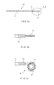
- FIG. 1 is a diagram showing an exemplary embolic coil to which embodiments of the present invention are applicable, and an exemplary delivery system for the coil.
- the coil delivery system 10 may be used, for example, for arterial and venous embolization via a catheter.
- a delivery wire 12 is inserted in a catheter (not shown) which has been introduced into the patient's vascular system.
- a distal portion 14 of the wire 12 may include radiopaque markers to facilitate positioning of a coil 16 at a desired location within the blood vessel (e.g., adjacent to the weakened or damaged portion thereof). All or part of the wire 12 may be flexible, so that it may follow the curvature of the catheter leading to the region of the vascular system to be treated.
- the coil 16 is shown in detail in Fig. 1A in a folded configuration, suitable for insertion through a catheter into the vascular system with minimal discomfort to the patient.
- the coil 16 may have the shape of a bundle of straight parallel wires.
- the deployed coil 16' shown in detail in Fig. 1B comprises several elements that confer to it the desired properties.
- a primary coil 20 forms the basic element of the embolic coil 16, and is generally formed by a tightly wound spiral of platinum wire. Those skilled in the art will understand that other suitably bio-compatible materials may be used instead of platinum so long as they possess appropriate mechanical properties.
- the primary coil 20 is, in turn, wound into another coiled shape to form a secondary coil 18 and to give an overall shape to the embolic coil 16.
- the secondary coil 18 may be a simple coil having a pitch and width that are substantially constant along its length. In the alternative, the pitch and width of the secondary coil 18 may vary in shape and dimension along its length, to fit into and to maintain its position in a specified space within the vascular system.
- an embolic coil 16' may also include a plurality of fibers 22 that extend from its surface.
- the fibers 22 increase the surface area of the coil 16' that is in contact with the flow of blood, and thus make the coil 16' more efficient at slowing the flow of blood therethrough. This enhances the formation of clots that will further preclude blood flow through the region where the coil 16' is deployed.
- the fibers 22 may be formed from strands of polymeric fibers such as Dacron or Nylon, or other durable materials that do not cause reactions with tissues of the human body.
- the fibers 22 may be held in place, for example, by friction between the loops of the primary coil 20, such that a certain amount of pressure between the loops is necessary to securely retain the fibers 22 therebetween.
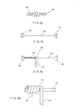
- Figures 2 and 3 show a conventional process for constructing the primary and secondary coils of an embolic coil.
- the coil is formed by first winding a platinum wire 50 on a primary winding mandrel 52.
- the resulting primary coil 54 has a wire-like elongated appearance, and can be treated as a flexible wire in subsequent operations.
- the process of winding the platinum wire 50 on the primary mandrel 52 performs cold work on the platinum wire 50, which as a result is plastically deformed into the coiled shape of the primary coil 54.
- the amount of cold work performed on the wire 50 determines how well the loops 56 retain their shape and remain tightly in contact with one another. The amount of cold work thus influences the ability of the primary coil 54 to retain the fibers 22 (shown in Fig. 1 ) that may be part of the embolic coil.
- a second step in constructing an embolic coil is shown in Fig. 4 .
- the primary coil 54 is in turn wound around a secondary coil mandrel 60 to form a secondary coil 62.
- the secondary mandrel 60 may have a cylindrical shape resulting in a simple cylindrical coil shape for the secondary coil 62, or may have a more complex shape, as shown, to generate the secondary coil 62 that conforms to a desired size and shape.
- the secondary coil 62 may have a variable coil diameter and/or a variable pitch.
- Exemplary shapes of the secondary coil include helices, vortices, flat spirals, complex spirals, 3D complex shapes etc., as required by any specific clinical application. The specific details of the size and shape of the secondary coil 62 thus can be selected to fit the requirements of the medical procedure for which the embolic coil is to be used.
- the assembly After the primary coil 54 has been wound around the secondary coil mandrel 60, heat is applied to the assembly to set and maintain the secondary coil 62 in the shape of the secondary winding mandrel 60.
- a temperature of 1000°F to 1200°F may be necessary to ensure that the secondary coil 62 retains its shape once it has been removed from the secondary winding mandrel 60.
- the shape of the secondary coil 62 is an important parameter which determines the anchorability of the device in the patient's vascular system.
- the various shapes that can be given to the secondary winding ensure that the embolic coil remains in position within the blood vessel, and is not dislodged by the movement of blood therethrough or by movements of the patient.
- an embolic coil may be designed so that, after introduction into a portion of a blood vessel weakened by an aneurysm, the embolic coil expands upon deployment to a helical, spiral or other shape that ensures the embolic coil will remain within the weakened portion of the blood vessel.
- Figure 4 shows an exemplary embodiment of fibers 22 being attached to the primary coil 54 of an embolic coil.
- the fibers 22 may be polymeric fibers or may be made of other flexible materials, for example, Nitinol.
- the fibers 22 are added to the platinum primary coil 54 to impart greater thrombogenicity to the overall embolic coil, and to increase its ability to stop the undesired flow of blood therethrough.
- the fibers 22 are generally inserted between the loops 56 of the primary coil 54, and are held in place by virtue of the cold work imparted to the platinum wire during the primary coil winding process.
- the insertion of the fibers 22 in the loops 56 is carried out after the heat treatment used to set and maintain the shape of the secondary coil 62.
- the retention of the fibers 22 between the loops 56 of the primary coil 54 is a function of the amount of cold work that has been performed and that continues to affect the platinum wire 50. In other words, the fibers 22 remain in place more securely when a large amount of cold work is performed that is not later removed.
- the overall anchorability of the embolic coil within a specified portion of the vascular system depends on retaining the specified shape of the embolic cord. This shape is best retained when the secondary winding of primary coil 54 on secondary mandrel 60 is subject to a high temperature for an extended time period. A high temperature treatment results in an embolic coil that maintains its complex three dimensional shape more accurately.
- the heating process used to set the shape of the secondary coil has an annealing effect on the platinum wire, which reverses the effect of the cold work performed when winding the primary coil.
- cold working a metal wire refers to causing plastic deformations to the metal which introduce strain in the crystal structure of the material. The strain results in hardening of the metal and changes the shape of the metal.
- Annealing refers to heating and then cooling a material to remove internal stresses and to make the material less brittle, so that the material becomes more flexible after annealing. In the case of the platinum wire wound onto the primary coil, annealing causes the coil loops 56 (shown in Fig.
- embolic coils are provided that exhibit both improved shape retention and improved fiber retention properties.
- the exemplary coils according to the invention are capable of retaining the fibers used to increase the device's thrombogenicity, while at the same time retaining their shape which makes them capable of remaining in position within the vascular system against forces applied by a strong flow of blood and other factors.
- the exemplary embolic coils are not treated with high heat to set and maintain the secondary coil shape. Instead, a memory shape material is used to impart to the assembly the secondary coil shape.
- the secondary coil 106 may have a variety of shapes, such as a spiral, an helix, a two or three dimensional complex shape, etc.
- conventional methods may be used to fix the shape of the shape memory alloy wire to the desired configuration. For example, plastic deformation of the wire when above a critical temperature of the material (the austenite finishing temperature Af), followed by cooling of the material may be carried out, so that the material will "remember" the shape imparted to it, as would be understood by those of skill in the art.
- the wire 100 retains the final general shape of the embolic coil, as shown in Fig. 5a .
- the wire 100 is then stretched between restraints 102 and is used as the winding mandrel to form the primary coil.
- the wire 100 may also be cooled below its critical temperature to facilitate the stretching operation.
- the critical temperature may below the operational temperature of the device, i.e. room temperature.
- a wire such as a platinum wire 104 is wound around the straightened and stretched shape memory wire 100, when the latter is below its critical temperature.
- the wire 104 assumes the shape of a primary coil 108, and at the same time it is subjected to cold work which plastically deforms it into the desired shape. Loops 110 are formed and are kept tight against one another by internal strain resulting from the cold work.
- the primary coil 108 may, for example, have a simple, cylindrical shape when the wire 104 is wound around a constant diameter mandrel such as the shape memory wire 100.
- the restraints 102 may be released to free the shape memory wire 100 to resume its previously memorized shape. If the stretching and primary coil winding are carried out at a temperature below the critical temperature of the shape memory wire 100, a temperature increase may be necessary to restore the wire 100 to its memorized shape. Otherwise, simply releasing the restraints 102 frees the shape memory wire 100 to resume the shape of secondary coil 106.
- the resulting embolic coil 116 is shown in Fig. 6 , where the shape of primary coil 108 is superimposed on the outline of the larger, more complex shape of the secondary coil 106.
- the embolic coil 116 thus comprises a Nitinol core wire disposed within the lumen of the platinum primary coil.
- Nitinol As would be understood by those of skill in the art, the shape memory properties of alloys such as Nitinol may be understood in terms of the phase transformations the alloy undergoes under various conditions. Shape memory refers to the ability of a structure to revert to an originally memorized shape after plastic deformation by heating it above a critical temperature. This plastic deformation may significant - to the extent that it would be permanent in a structure formed of non-shape memory material.
- These Nitinol alloys can exist in two conditions, depending on the temperature and the strains applied thereto. At temperatures above the critical temperature the alloy is in an austenite phase and, below that temperature, it remains in a martensite phase. In addition, austenitic portions of the alloy may become martensitic when a strain is applied thereto.
- Heating the alloy above the critical temperature in a desired shape causes the alloy to "memorize" that shape. As the temperature is lowered below the critical temperature, the alloy changes phase and becomes malleable in the martensite phase. If a strain is then applied to the alloy element to plastically deform it, the alloy remains martensitic, but now has a different shape due to the deformation. As this deformation is plastic, this new shape is maintained even after the strain has been removed. If the alloy element is later heated above the critical temperature, a thermoelastic martensitic transformation takes place and the element returns to its original memorized shape, regaining the strength and rigidity of the austenitic phase.
- alloys such as Nitinol also exhibit superelasticity effects. That is, when a strain is applied to the alloy element in the austenitic phase, the element deforms this deformation may generate large areas of strain-induced martensite material even if there is no temperature change. These areas occur primarily at points of where the strain is highest and may result in deformations that would be unrecoverable in normal materials. However, at that temperature martensite is not the stable phase of the alloy, and as soon as the strain has been removed the alloy returns to an austenitic state and reverts to its original shape. Superelasticity thus refers to the ability of the alloy, while in the austenitic state, to deform under strain to a very large degree, without having this deformation become permanent.
- Superelasticity effects are useful in devices designed for use within the human body.
- a superelastic embolic coil according to embodiments of the invention can easily be restrained into a small, streamlined configuration for insertion into the body, for example through a catheter. Then, when the embolic coil has been positioned at a desired location within the vascular system, restraints may be removed allowing the coil to deploy to an expanded operational configuration.
- Superelasticity also allows the coil to bend greatly due to, e.g., strains imparted during normal activities of the patient, without losing its ability to return to its operational state after the strains have been removed.
- the Embolic coil 116 thus includes a shape memory core element, for example a wire made of Nitinol, which gives to the assembly the secondary coil shape 106.
- a shape memory core element for example a wire made of Nitinol, which gives to the assembly the secondary coil shape 106.
- an elongated outer element such as another wire made, for example, of platinum, which forms the primary coil 108 of the device. Fibers may be added to the primary coil 108 to increase the thrombogenicity of the coil, as discussed above. Since little or no annealing takes place according to embodiments of the invention, the cold work applied during primary winding is not reduced, and thus fiber retention between the loops 110 of primary coil 108 is maximized.
- Embodiments of the present invention thus exhibit both enhanced fiber retention due to the high cold work applied to the primary coil and enhanced shape retention which translates to easy anchorability in position due to the shape memory alloy core.
- the shape memory core wire 120 may comprise cylindrical grooves 124 that are used as anchors for fibers. Grooves 124 channel the fiber bundles around core wire 120, so that they are held in place by the core wire 120. In this manner the primary coil 108 is freed from that function. Channeling the fiber bundles via grooves 124 promotes cohesion of the fibers, and reduced the loss of fibers during use of the embolic coil.
- a shape memory core wire 122 may comprise spiral grooves 126, which also help anchor fibers such as the fibers 22 shown in Fig. 4 . In these embodiments, the amount of cold work imparted to the primary coil 108 has less effect on how well the fibers 22 are retained, and fewer restrictions are imposed on the shape and properties of the primary coil 108.
- the platinum wire forming the primary coil 108 may be co-wound with a second wire made of a shape memory material.
- a heat setting process may be used to set and maintain the shape of the primary coil 108, by relying on the properties of the shape memory material wire. More complex designs of the primary coil 108 may thus be obtained without reducing the fiber retention capability of the device.
- the embolic coils formed according to embodiments of the present invention exhibit advantageous characteristics that make them well suited for use in medical procedures. For example, greater anchorability due to good shape retention and greater fiber retention may be obtained at the same time. Minimization or outright elimination of the high temperature heat treatment process to set and maintain the secondary coil shape increases the manufacturing process throughput, while reduced platinum coil deformation reduces the loss of material due to scrap.
- the presence of the Nitinol core makes the embolic coil assembly less likely to bind, so that delivery to a selected location within the patient's vascular system is simplified. Since the shape retention / anchorability role is taken up by the shape memory core wire, a smaller profile of the embolic coil is possible.
- the embodiments according to the invention may provide the anchorability of an 0.035 in. diameter coil in a device having the profile of an 0.010 in. to 0.018 in. coil.
Abstract
Description
- Many clinical situations require the reduction or complete stoppage of blood flow to some region of the patient's body. Embolic coils are one example of devices that may be used to stop undesired blood flow in situations, for example, requiring treatment of aneurysms, arteriovenous malformations, traumatic fistulae and tumor embolization. These conditions require that the blood flow through a portion of a blood vessel be stopped, for example by introducing an artificial device into the vessel to slow the flow to allow the natural clotting process form a more complete blockage.
- Embolic coils are made from a bio-compatible material, such as platinum, to minimize problems associated with tissue irritation and rejection. These coils are often shaped as complex three dimensional curves that fill in portions of a blood vessel's lumen and slow blood flow therethrough. Often, polymeric fibers are added to the metallic coils to enhance the coil's thrombogenicity (i.e., its ability to cause the formation of clots).
- In the treatment for an aneurysm, an embolic coil is inserted in the affected blood vessel using a catheter, and is placed within the bulging, weakened section of the blood vessel. When in place, the coil expands to its operational size and shape, and slows down the flow of blood through the weakened section. Over time, a clot forms around the embolic coil, and blood flow through the weakened section is completely blocked. Thus, failure of this weakened section is less likely and the resulting hemorrhage may be prevented.
- Typical embolic coils are formed using two major steps: 1) a wire of platinum or other bio-compatible material is wound into a spring, forming what is commonly referred to as a primary coil; and 2) the primary coil is in turn wound around a mandrel having a more complex shape and is subject to high heat to yield a secondary coil. The secondary coil thus is a coiled wire of complex-shape. Subsequently, polymeric fibers may be added to the embolic coil, usually between the rings of the primary coil.
- In one aspect, the present invention is directed to an embolic coil comprising an elongated core element formed of a shape memory material treated to define a memorized secondary coil shape and an elongated outer element wound around the elongated core element to define a primary coil shape of the embolic coil. The invention also includes a method of forming an embolic coil which comprises the steps of setting a shape memory core element to a shape defining a secondary coil shape of the embolic coil, straightening the core element, winding an elongated outer element around the straightened core element to form a primary coil of the embolic coil, and releasing the straightened core element to form the secondary coil of the embolic coil.
- In another aspect, the invention is directed to a method of forming an embolic coil, comprising the steps of imparting a memorized shape to a core element formed of a shape memory material, wherein the memorized shape defines a secondary coil of the embolic coil and straightening the core element in combination with the steps of winding an elongated outer element around the straightened core element to form a primary coil of the embolic coil and releasing the straightened core element when the device has been positioned at a deployment location to form the secondary coil of the embolic coil.
- The following aspects are preferred embodiments of the invention.
- 1. An embolic coil comprising:
- an elongated core element formed of a shape memory material treated to define a memorized secondary coil shape; and
- an elongated outer element wound around the elongated core element to define a primary coil shape of the embolic coil.
- 2. The embolic coil according to aspect 1, wherein the shape memory material of which the elongated core element is formed is, at an operational temperature of the embolic coil, in an austenitic phase.
- 3. The embolic coil according to aspect 1, further comprising a plurality of fibers extending therefrom.
- 4. The embolic coil according to aspect 3, wherein the elongated outer element is adapted to retain the plurality of fibers attached to the embolic coil.
- 5. The embolic coil according to aspect 1, wherein a shape of the primary coil is defined by applying cold work to the elongated outer element.
- 6. The embolic coil according to aspect 1, wherein the memorized shape of the elongated core element is substantially a coil.
- 7. The embolic coil according to aspect 1, wherein the memorized shape of the elongated core element is substantially a three dimensional spiral.
- 8. The embolic coil according to aspect 1, wherein the shape memory material of which the elongated core element is formed includes Nitinol.
- 9. The embolic coil according to aspect 1, wherein the elongated outer element is formed of platinum.
- 10. The embolic coil according to aspect 1, wherein the primary coil shape is a substantially cylindrical coil.
- 11. The embolic coil according to aspect 1, further comprising a plurality of fiber retention grooves formed on the elongated core element.
- 12. The embolic coil according to aspect 1, wherein the elongated outer element comprises a platinum wire co-wound with a wire formed of a shape memory material.
- 13. A method of forming an embolic coil, comprising the steps of:
- imparting a memorized shape to a core element formed of a shape memory material, wherein the memorized shape defines a secondary coil of the embolic coil;
- straightening the core element;
- winding an elongated outer element around the straightened core element to form a primary coil of the embolic coil; and
- releasing the straightened core element when the device has been positioned at a deployment location to form the secondary coil of the embolic coil.
- 14. The method according to aspect 13, further comprising the step of attaching fibers to the embolic coil.
- 15. The method according to
aspect 14, wherein the fibers are attached to the primary coil. - 16. The method according to
aspect 14, wherein the fibers are attached to grooves formed in the core element. - 17. The method according to aspect 13, further comprising the step of cooling the shape memory core element below a critical temperature before straightening the core element.
- 18. The method according to aspect 13, wherein the core element is released in an environment having a temperature above a critical temperature of the shape memory material.
- 19. The method according to aspect 13, wherein the secondary coil shape is one of a spiral, helix, vortex, and three-dimensional spiral.
- 20. The method according to aspect 13, wherein the elongated outer element is formed of a platinum wire.
- 21. The method according to
aspect 20, further comprising the step of co-winding the platinum wire with a wire formed of a shape memory material. - 22. The method according to aspect 13, wherein the core element is formed of a Nitinol wire.
- 23. The method according to aspect 13, further comprising the step of forming fiber retention grooves in the core element.
- 24. A coiled medical device for implantation in a patient comprising:
- a primary coil having a primary coil shape, the primary coil defining a lumen extending therethrough; and
- a secondary coil formed of a shape memory material and disposed in the lumen, the secondary coil having a secondary coil memorized shape, wherein, when heated to a temperature above a critical temperature of the shape memory material, the secondary coil causes the primary coil to follow the secondary coil shape.
- 25. The medical device according to aspect 24, further comprising fiber-like elements attached to the primary coil.
- 26. The medical device according to aspect 24, wherein the shape memory material includes Nitinol.
-
-
Figure 1A is a diagram showing an exemplary embolic coil according to the present invention; -
Figure 1B shows a detailed view of the coil ofFig. 1A in a pre-deployment configuration; -
Figure 1C shows a detailed view of the coil ofFig. 1A in a post-deployment configuration; -
Figure 2 is a diagram showing a primary coil winding for an embolic coil according to an embodiment of the invention; -
Figure 3 is a diagram showing a secondary coil winding for a conventional embolic coil; -
Figure 4 is a diagram showing attachment of polymeric fibers to the primary coil according to an embodiment of the invention; -
Figure 5 is a diagram showing a shape memory primary coil / mandrel according to an embodiment of the invention; -
Figure 6 is a diagram showing winding of a platinum wire on a shape memory mandrel according to an embodiment of the present invention; -
Figure 7 is a diagram showing a Nitinol winding core with fiber retainers according to an embodiment of the invention; and -
Figure 8 is a diagram showing a Nitinol winding core with fiber retainers according to a second embodiment of the invention. - The present invention may be further understood with reference to the following description and the appended drawings, wherein like elements are referred to with the same reference numerals. The present invention is related to medical devices used to block the flow of blood through a blood vessel such as, for example, embolic coils. Although the following description relates primarily to embolic coils having a primary and secondary coil winding, the invention is also applicable to other devices that include in their construction complex coil shapes.
- Traditionally, aneurysms have been very difficult to diagnose, since the patients are generally asymptomatic until the aneurysm bursts. At that point, most of the damage has already taken place, and available medical therapies have been limited. Even in cases where the aneurysm has been identified prior to bursting, the medical options have been limited, because the aneurysm is often in locations that are difficult to reach by surgery, and repairing the damaged blood vessel may be impossible. Recent advances in visualization methods, however, have made the early identification of aneurysms and similar problems more common. Once the aneurysm has been located, it may be treated by blocking the supply of blood to the weakened area even if surgery to repair the blood vessel is not practical.
-
Figure 1 is a diagram showing an exemplary embolic coil to which embodiments of the present invention are applicable, and an exemplary delivery system for the coil. Thecoil delivery system 10 may be used, for example, for arterial and venous embolization via a catheter. Adelivery wire 12 is inserted in a catheter (not shown) which has been introduced into the patient's vascular system. Adistal portion 14 of thewire 12 may include radiopaque markers to facilitate positioning of acoil 16 at a desired location within the blood vessel (e.g., adjacent to the weakened or damaged portion thereof). All or part of thewire 12 may be flexible, so that it may follow the curvature of the catheter leading to the region of the vascular system to be treated. - The
coil 16 is shown in detail inFig. 1A in a folded configuration, suitable for insertion through a catheter into the vascular system with minimal discomfort to the patient. For example, in the folded configuration, thecoil 16 may have the shape of a bundle of straight parallel wires. Once thecoil 16 has reached the desired position within the vascular system, it may be deployed to its operative configuration and released from thewire 12 so that it will remain in position at the proper location. The deployed coil 16' shown in detail inFig. 1B comprises several elements that confer to it the desired properties. Aprimary coil 20 forms the basic element of theembolic coil 16, and is generally formed by a tightly wound spiral of platinum wire. Those skilled in the art will understand that other suitably bio-compatible materials may be used instead of platinum so long as they possess appropriate mechanical properties. Theprimary coil 20 is, in turn, wound into another coiled shape to form asecondary coil 18 and to give an overall shape to theembolic coil 16. Thesecondary coil 18 may be a simple coil having a pitch and width that are substantially constant along its length. In the alternative, the pitch and width of thesecondary coil 18 may vary in shape and dimension along its length, to fit into and to maintain its position in a specified space within the vascular system. - Optionally, an embolic coil 16' may also include a plurality of
fibers 22 that extend from its surface. Thefibers 22 increase the surface area of the coil 16' that is in contact with the flow of blood, and thus make the coil 16' more efficient at slowing the flow of blood therethrough. This enhances the formation of clots that will further preclude blood flow through the region where the coil 16' is deployed. For example, thefibers 22 may be formed from strands of polymeric fibers such as Dacron or Nylon, or other durable materials that do not cause reactions with tissues of the human body. Thefibers 22 may be held in place, for example, by friction between the loops of theprimary coil 20, such that a certain amount of pressure between the loops is necessary to securely retain thefibers 22 therebetween. -
Figures 2 and 3 show a conventional process for constructing the primary and secondary coils of an embolic coil. In this process, the coil is formed by first winding aplatinum wire 50 on a primary windingmandrel 52. The resultingprimary coil 54 has a wire-like elongated appearance, and can be treated as a flexible wire in subsequent operations. The process of winding theplatinum wire 50 on theprimary mandrel 52 performs cold work on theplatinum wire 50, which as a result is plastically deformed into the coiled shape of theprimary coil 54. The amount of cold work performed on thewire 50 determines how well theloops 56 retain their shape and remain tightly in contact with one another. The amount of cold work thus influences the ability of theprimary coil 54 to retain the fibers 22 (shown inFig. 1 ) that may be part of the embolic coil. - A second step in constructing an embolic coil is shown in
Fig. 4 . In this step, theprimary coil 54 is in turn wound around asecondary coil mandrel 60 to form asecondary coil 62. Thesecondary mandrel 60 may have a cylindrical shape resulting in a simple cylindrical coil shape for thesecondary coil 62, or may have a more complex shape, as shown, to generate thesecondary coil 62 that conforms to a desired size and shape. For example, thesecondary coil 62 may have a variable coil diameter and/or a variable pitch. Exemplary shapes of the secondary coil include helices, vortices, flat spirals, complex spirals, 3D complex shapes etc., as required by any specific clinical application. The specific details of the size and shape of thesecondary coil 62 thus can be selected to fit the requirements of the medical procedure for which the embolic coil is to be used. - After the
primary coil 54 has been wound around thesecondary coil mandrel 60, heat is applied to the assembly to set and maintain thesecondary coil 62 in the shape of the secondary windingmandrel 60. For example, a temperature of 1000°F to 1200°F may be necessary to ensure that thesecondary coil 62 retains its shape once it has been removed from the secondary windingmandrel 60. The shape of thesecondary coil 62 is an important parameter which determines the anchorability of the device in the patient's vascular system. The various shapes that can be given to the secondary winding ensure that the embolic coil remains in position within the blood vessel, and is not dislodged by the movement of blood therethrough or by movements of the patient. For example, an embolic coil may be designed so that, after introduction into a portion of a blood vessel weakened by an aneurysm, the embolic coil expands upon deployment to a helical, spiral or other shape that ensures the embolic coil will remain within the weakened portion of the blood vessel. -
Figure 4 shows an exemplary embodiment offibers 22 being attached to theprimary coil 54 of an embolic coil. As indicated above, thefibers 22 may be polymeric fibers or may be made of other flexible materials, for example, Nitinol. Thefibers 22 are added to the platinumprimary coil 54 to impart greater thrombogenicity to the overall embolic coil, and to increase its ability to stop the undesired flow of blood therethrough. Thefibers 22 are generally inserted between theloops 56 of theprimary coil 54, and are held in place by virtue of the cold work imparted to the platinum wire during the primary coil winding process. In an exemplary embodiment, the insertion of thefibers 22 in theloops 56 is carried out after the heat treatment used to set and maintain the shape of thesecondary coil 62. - However, other processes may be better suited to forming embolic coils having enhanced shape retention and fiber retention properties. Specifically, the retention of the
fibers 22 between theloops 56 of theprimary coil 54 is a function of the amount of cold work that has been performed and that continues to affect theplatinum wire 50. In other words, thefibers 22 remain in place more securely when a large amount of cold work is performed that is not later removed. On the other hand, the overall anchorability of the embolic coil within a specified portion of the vascular system depends on retaining the specified shape of the embolic cord. This shape is best retained when the secondary winding ofprimary coil 54 onsecondary mandrel 60 is subject to a high temperature for an extended time period. A high temperature treatment results in an embolic coil that maintains its complex three dimensional shape more accurately. - The heating process used to set the shape of the secondary coil, however, has an annealing effect on the platinum wire, which reverses the effect of the cold work performed when winding the primary coil. On a molecular level, cold working a metal wire refers to causing plastic deformations to the metal which introduce strain in the crystal structure of the material. The strain results in hardening of the metal and changes the shape of the metal. Annealing refers to heating and then cooling a material to remove internal stresses and to make the material less brittle, so that the material becomes more flexible after annealing. In the case of the platinum wire wound onto the primary coil, annealing causes the coil loops 56 (shown in
Fig. 4 ) to be kept together less tightly, so that thefibers 22 are not retained with as much force as before the annealing. Construction of the embolic coil using this procedure therefore involves a compromise between the shape retention properties and the fiber retention properties of the finished coil, since the high temperature treatment used for better shape retention also anneals the cold work from primary winding, leading to reduced fiber retention. - According to further embodiments of the present invention, embolic coils are provided that exhibit both improved shape retention and improved fiber retention properties. The exemplary coils according to the invention are capable of retaining the fibers used to increase the device's thrombogenicity, while at the same time retaining their shape which makes them capable of remaining in position within the vascular system against forces applied by a strong flow of blood and other factors. According to embodiments of the invention, the exemplary embolic coils are not treated with high heat to set and maintain the secondary coil shape. Instead, a memory shape material is used to impart to the assembly the secondary coil shape.
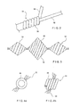
- As shown in
Figure 5 , acore wire 100 made of a shape memory material, such as Nitinol, is formed in the shape of a secondary coil 106 (Fig. 5a ). As indicated above, thesecondary coil 106 may have a variety of shapes, such as a spiral, an helix, a two or three dimensional complex shape, etc. As will be apparent to those of skill in the art, conventional methods may be used to fix the shape of the shape memory alloy wire to the desired configuration. For example, plastic deformation of the wire when above a critical temperature of the material (the austenite finishing temperature Af), followed by cooling of the material may be carried out, so that the material will "remember" the shape imparted to it, as would be understood by those of skill in the art. Once the desired shape for thewire 100 has been memorized, thewire 100 retains the final general shape of the embolic coil, as shown inFig. 5a . As shown inFig. 5b , thewire 100 is then stretched betweenrestraints 102 and is used as the winding mandrel to form the primary coil. In this step, thewire 100 may also be cooled below its critical temperature to facilitate the stretching operation. For example, the critical temperature may below the operational temperature of the device, i.e. room temperature. - In one exemplary embodiment shown in
Figure 5c , a wire such as aplatinum wire 104 is wound around the straightened and stretchedshape memory wire 100, when the latter is below its critical temperature. As thewire 104 is wound, it assumes the shape of aprimary coil 108, and at the same time it is subjected to cold work which plastically deforms it into the desired shape.Loops 110 are formed and are kept tight against one another by internal strain resulting from the cold work. As described above, theprimary coil 108 may, for example, have a simple, cylindrical shape when thewire 104 is wound around a constant diameter mandrel such as theshape memory wire 100. - Once the primary coil winding of the
wire 104 over the mandrel /shape memory wire 100 has been completed, therestraints 102 may be released to free theshape memory wire 100 to resume its previously memorized shape. If the stretching and primary coil winding are carried out at a temperature below the critical temperature of theshape memory wire 100, a temperature increase may be necessary to restore thewire 100 to its memorized shape. Otherwise, simply releasing therestraints 102 frees theshape memory wire 100 to resume the shape ofsecondary coil 106. The resultingembolic coil 116 is shown inFig. 6 , where the shape ofprimary coil 108 is superimposed on the outline of the larger, more complex shape of thesecondary coil 106. According to embodiments of the invention, no heat treatment or only minimal heat treatment is necessary to set and maintain the secondary coil shape. Thus the cold work imparted to the platinum wire during primary winding is not adversely affected by subsequent annealing. According to the present exemplary embodiment, theembolic coil 116 thus comprises a Nitinol core wire disposed within the lumen of the platinum primary coil. - As would be understood by those of skill in the art, the shape memory properties of alloys such as Nitinol may be understood in terms of the phase transformations the alloy undergoes under various conditions. Shape memory refers to the ability of a structure to revert to an originally memorized shape after plastic deformation by heating it above a critical temperature. This plastic deformation may significant - to the extent that it would be permanent in a structure formed of non-shape memory material. These Nitinol alloys can exist in two conditions, depending on the temperature and the strains applied thereto. At temperatures above the critical temperature the alloy is in an austenite phase and, below that temperature, it remains in a martensite phase. In addition, austenitic portions of the alloy may become martensitic when a strain is applied thereto.
- Heating the alloy above the critical temperature in a desired shape causes the alloy to "memorize" that shape. As the temperature is lowered below the critical temperature, the alloy changes phase and becomes malleable in the martensite phase. If a strain is then applied to the alloy element to plastically deform it, the alloy remains martensitic, but now has a different shape due to the deformation. As this deformation is plastic, this new shape is maintained even after the strain has been removed. If the alloy element is later heated above the critical temperature, a thermoelastic martensitic transformation takes place and the element returns to its original memorized shape, regaining the strength and rigidity of the austenitic phase.
- Those skilled in the art will also understand that alloys such as Nitinol also exhibit superelasticity effects. That is, when a strain is applied to the alloy element in the austenitic phase, the element deforms this deformation may generate large areas of strain-induced martensite material even if there is no temperature change. These areas occur primarily at points of where the strain is highest and may result in deformations that would be unrecoverable in normal materials. However, at that temperature martensite is not the stable phase of the alloy, and as soon as the strain has been removed the alloy returns to an austenitic state and reverts to its original shape. Superelasticity thus refers to the ability of the alloy, while in the austenitic state, to deform under strain to a very large degree, without having this deformation become permanent.
- Superelasticity effects are useful in devices designed for use within the human body. For example, a superelastic embolic coil according to embodiments of the invention can easily be restrained into a small, streamlined configuration for insertion into the body, for example through a catheter. Then, when the embolic coil has been positioned at a desired location within the vascular system, restraints may be removed allowing the coil to deploy to an expanded operational configuration. Superelasticity also allows the coil to bend greatly due to, e.g., strains imparted during normal activities of the patient, without losing its ability to return to its operational state after the strains have been removed.
- According to embodiments of the present invention, the
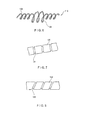
Embolic coil 116 thus includes a shape memory core element, for example a wire made of Nitinol, which gives to the assembly thesecondary coil shape 106. Around the shape memory core element is wound an elongated outer element, such as another wire made, for example, of platinum, which forms theprimary coil 108 of the device. Fibers may be added to theprimary coil 108 to increase the thrombogenicity of the coil, as discussed above. Since little or no annealing takes place according to embodiments of the invention, the cold work applied during primary winding is not reduced, and thus fiber retention between theloops 110 ofprimary coil 108 is maximized. Embodiments of the present invention thus exhibit both enhanced fiber retention due to the high cold work applied to the primary coil and enhanced shape retention which translates to easy anchorability in position due to the shape memory alloy core. - Additional enhancements may be made to the embolic coil according to the present invention, to improve the device's fiber retention properties. For example, as shown in
Figure 7 , the shapememory core wire 120 may comprisecylindrical grooves 124 that are used as anchors for fibers.Grooves 124 channel the fiber bundles aroundcore wire 120, so that they are held in place by thecore wire 120. In this manner theprimary coil 108 is freed from that function. Channeling the fiber bundles viagrooves 124 promotes cohesion of the fibers, and reduced the loss of fibers during use of the embolic coil. In a different embodiment shown inFigure 8 , a shapememory core wire 122 may comprisespiral grooves 126, which also help anchor fibers such as thefibers 22 shown inFig. 4 . In these embodiments, the amount of cold work imparted to theprimary coil 108 has less effect on how well thefibers 22 are retained, and fewer restrictions are imposed on the shape and properties of theprimary coil 108. - In a different embodiment, the platinum wire forming the
primary coil 108 may be co-wound with a second wire made of a shape memory material. A heat setting process may be used to set and maintain the shape of theprimary coil 108, by relying on the properties of the shape memory material wire. More complex designs of theprimary coil 108 may thus be obtained without reducing the fiber retention capability of the device. - The embolic coils formed according to embodiments of the present invention exhibit advantageous characteristics that make them well suited for use in medical procedures. For example, greater anchorability due to good shape retention and greater fiber retention may be obtained at the same time. Minimization or outright elimination of the high temperature heat treatment process to set and maintain the secondary coil shape increases the manufacturing process throughput, while reduced platinum coil deformation reduces the loss of material due to scrap. The presence of the Nitinol core makes the embolic coil assembly less likely to bind, so that delivery to a selected location within the patient's vascular system is simplified. Since the shape retention / anchorability role is taken up by the shape memory core wire, a smaller profile of the embolic coil is possible. For example, the embodiments according to the invention may provide the anchorability of an 0.035 in. diameter coil in a device having the profile of an 0.010 in. to 0.018 in. coil.
- The present invention has been described with reference to specific embodiments associated with an embolic coil having a Nitinol core wire surrounded by a Platinum primary coil. However, other embodiments may be devised that are applicable to other medical devices, without departing from the scope of the invention. In particular, other shape memory metal alloys or polymers may be used in the invention in conjunction with any other suitable biocompatible materials. Accordingly, various modifications and changes may be made to the embodiments without departing from the broadest spirit and scope of the present invention as set forth in the claims that follow. The specification and drawings are accordingly to be regarded in an illustrative rather than restrictive sense.
Claims (14)
- A system for delivering an embolic coil (16) to the vasculature of a patient comprising:a catheter;a delivery wire (12) inserted in the catheter; andan embolic coil (16) deployable from a distal portion (14) of said delivery wire (12), said embolic coil (16) comprising
an elongated core element formed of a shape memory material treated to define a memorized secondary coil shape (18);
an elongated outer element wound around the elongated core element to define a primary coil shape (20) of the embolic coil (16); and
a plurality of fibers (22) extending from the embolic coil (16);wherein said embolic coil is suitable for insertion through said catheter. - The system of claim 1, wherein a distal portion of said delivery wire (12) includes a radiopaque marker.
- The system of claim 1, wherein the shape memory material of which the elongated core element (12) is formed is, at an operational temperature of the embolic coil (16), in an austenitic phase.
- The system of claim 1, wherein the plurality of fibers (22) extending therefrom are formed of a flexible polymer.
- The system of claim 1, wherein the elongated outer element is adapted to retain the plurality of fibers (22) attached to the embolic coil (16).
- The system of claim 1, wherein the memorized shape is defined by applying cold work to the elongated outer element.
- The system of claim 1, wherein the memorized shape of the elongated core element is substantially a coil.
- The system of claim 1, wherein the memorized shape of the elongated core element is substantially a three-dimensional spiral.
- The system of claim 1, wherein the shape memory material of which the elongated core material is formed includes Nitinol.
- The system of claim 1, wherein the elongated outer element is formed of platinum.
- The system of claim 1, wherein the primary coil shape (20) is a substantially cylindrical coil.
- The system of claim 1, further comprising a plurality of fiber retention grooves formed on the elongated core element.
- The system of claim 1, wherein the elongated outer element comprises a platinum wire co-wound with a wire formed of a shape memory material.
- The system of claim 1 for use in medicine.
Applications Claiming Priority (3)
| Application Number | Priority Date | Filing Date | Title |
|---|---|---|---|
| US10/626,246 US8043321B2 (en) | 2003-07-24 | 2003-07-24 | Embolic coil |
| PCT/US2004/021057 WO2005009253A1 (en) | 2003-07-24 | 2004-06-28 | Improved embolic coil |
| EP20040777333 EP1648312B1 (en) | 2003-07-24 | 2004-06-28 | Improved embolic coil |
Related Parent Applications (2)
| Application Number | Title | Priority Date | Filing Date |
|---|---|---|---|
| EP20040777333 Division-Into EP1648312B1 (en) | 2003-07-24 | 2004-06-28 | Improved embolic coil |
| EP20040777333 Division EP1648312B1 (en) | 2003-07-24 | 2004-06-28 | Improved embolic coil |
Publications (2)
| Publication Number | Publication Date |
|---|---|
| EP2805681A1 true EP2805681A1 (en) | 2014-11-26 |
| EP2805681B1 EP2805681B1 (en) | 2019-09-04 |
Family
ID=34080390
Family Applications (2)
| Application Number | Title | Priority Date | Filing Date |
|---|---|---|---|
| EP14181493.9A Active EP2805681B1 (en) | 2003-07-24 | 2004-06-28 | Improved embolic coil |
| EP20040777333 Active EP1648312B1 (en) | 2003-07-24 | 2004-06-28 | Improved embolic coil |
Family Applications After (1)
| Application Number | Title | Priority Date | Filing Date |
|---|---|---|---|
| EP20040777333 Active EP1648312B1 (en) | 2003-07-24 | 2004-06-28 | Improved embolic coil |
Country Status (4)
| Country | Link |
|---|---|
| US (1) | US8043321B2 (en) |
| EP (2) | EP2805681B1 (en) |
| JP (1) | JP4696064B2 (en) |
| WO (1) | WO2005009253A1 (en) |
Families Citing this family (34)
| Publication number | Priority date | Publication date | Assignee | Title |
|---|---|---|---|---|
| US7416757B2 (en) * | 2004-04-08 | 2008-08-26 | Cordis Neurovascular, Inc. | Method of making active embolic coil |
| WO2006032289A1 (en) | 2004-09-22 | 2006-03-30 | Dendron Gmbh | Medical implant |
| US8425550B2 (en) * | 2004-12-01 | 2013-04-23 | Boston Scientific Scimed, Inc. | Embolic coils |
| US8152839B2 (en) * | 2005-12-19 | 2012-04-10 | Boston Scientific Scimed, Inc. | Embolic coils |
| US20070225738A1 (en) * | 2006-03-24 | 2007-09-27 | Cook Incorporated | Aneurysm coil and method of assembly |
| WO2008041094A2 (en) * | 2006-10-06 | 2008-04-10 | Lithotech Medical Ltd. | Retrieval snare for extracting foreign objects from body cavities and method for manufacturing thereof |
| US8801747B2 (en) * | 2007-03-13 | 2014-08-12 | Covidien Lp | Implant, a mandrel, and a method of forming an implant |
| US8361138B2 (en) * | 2007-07-25 | 2013-01-29 | Aga Medical Corporation | Braided occlusion device having repeating expanded volume segments separated by articulation segments |
| DE102007038446A1 (en) * | 2007-08-14 | 2009-02-19 | pfm Produkte für die Medizin AG | Embolisiereinrichtung |
| JP5580737B2 (en) * | 2007-08-17 | 2014-08-27 | ミクラス エンドバスキュラー エルエルシー | Twisted primary wind coil for vascular treatment, method for forming the same, and secondary wind coil |
| US9808252B2 (en) | 2009-04-02 | 2017-11-07 | Endoshape, Inc. | Vascular occlusion devices |
| AU2010339980C1 (en) * | 2009-12-16 | 2014-07-10 | Endoshape, Inc. | Multi-fiber shape memory device |
| US10010327B2 (en) * | 2010-12-16 | 2018-07-03 | Lawrence Livermore National Security, Llc | Expandable implant and implant system |
| US20120271409A1 (en) * | 2011-04-25 | 2012-10-25 | Medtronic Vascular, Inc. | Helical Radiopaque Marker |
| US9504474B2 (en) | 2011-05-23 | 2016-11-29 | Stryker Corporation | Vaso-occlusive devices with in-situ stiffening |
| US9017366B2 (en) * | 2011-08-19 | 2015-04-28 | Empirilon Technology, Llc | Methods and systems for performing intralumenal procedures |
| US10342548B2 (en) | 2012-01-13 | 2019-07-09 | W. L. Gore & Associates, Inc. | Occlusion devices and methods of their manufacture and use |
| AU2013209672B2 (en) | 2012-01-17 | 2015-11-19 | Endoshape, Inc. | Occlusion device for a vascular or biological lumen |
| US9011480B2 (en) | 2012-01-20 | 2015-04-21 | Covidien Lp | Aneurysm treatment coils |
| US9687245B2 (en) | 2012-03-23 | 2017-06-27 | Covidien Lp | Occlusive devices and methods of use |
| US9119948B2 (en) | 2013-02-20 | 2015-09-01 | Covidien Lp | Occlusive implants for hollow anatomical structures, delivery systems, and related methods |
| CA2903834C (en) | 2013-03-13 | 2018-07-24 | Endoshape, Inc. | Continuous embolic coil and methods and devices for delivery of the same |
| CN108186074A (en) | 2014-02-27 | 2018-06-22 | 因库麦迪斯有限公司 | For treating the framework microcoils of vascular diseases |
| US9713475B2 (en) | 2014-04-18 | 2017-07-25 | Covidien Lp | Embolic medical devices |
| EP3328457B8 (en) | 2015-07-27 | 2021-06-16 | The Texas A&M University System | Medical devices coated with shape memory polymer foams |
| US20170189033A1 (en) * | 2016-01-06 | 2017-07-06 | Microvention, Inc. | Occlusive Embolic Coil |
| JP6418613B2 (en) * | 2016-05-31 | 2018-11-07 | 国立大学法人信州大学 | Embolic coil |
| US11219520B2 (en) | 2017-03-14 | 2022-01-11 | Shape Memory Medical, Inc. | Shape memory polymer foams to seal space around valves |
| CN109044467B (en) * | 2018-09-17 | 2024-01-05 | 南京思脉德医疗科技有限公司 | Dual-crest three-trough reducing two-dimensional embolic coil |
| CN109223084A (en) * | 2018-09-17 | 2019-01-18 | 南京思脉德医疗科技有限公司 | A kind of more handles concatenation shape embolism spring rings of more balls |
| US11399840B2 (en) | 2019-08-13 | 2022-08-02 | Covidien Lp | Implantable embolization device |
| CN116370007A (en) * | 2019-12-24 | 2023-07-04 | 上海微创心脉医疗科技(集团)股份有限公司 | Plugging device and system |
| CN113017746A (en) * | 2019-12-24 | 2021-06-25 | 上海微创心脉医疗科技(集团)股份有限公司 | Interlayer crevasse plugging system |
| US11134954B1 (en) | 2021-02-01 | 2021-10-05 | Accumedical Beijing Ltd. | Braided embolization apparatus |
Citations (3)
| Publication number | Priority date | Publication date | Assignee | Title |
|---|---|---|---|---|
| EP0820726A2 (en) * | 1996-07-26 | 1998-01-28 | Target Therapeutics, Inc. | Aneurysm closure device assembly |
| WO1999040852A1 (en) * | 1998-02-13 | 1999-08-19 | Boston Scientific Limited | Vaso-occlusive device with attached polymeric fibres |
| WO2000074577A1 (en) * | 1999-06-04 | 2000-12-14 | Scimed Life Systems, Inc. | Polymer covered vaso-occlusive devices and methods of producing such devices |
Family Cites Families (28)
| Publication number | Priority date | Publication date | Assignee | Title |
|---|---|---|---|---|
| US5851206A (en) * | 1990-03-13 | 1998-12-22 | The Regents Of The University Of California | Method and apparatus for endovascular thermal thrombosis and thermal cancer treatment |
| US6083220A (en) * | 1990-03-13 | 2000-07-04 | The Regents Of The University Of California | Endovascular electrolytically detachable wire and tip for the formation of thrombus in arteries, veins, aneurysms, vascular malformations and arteriovenous fistulas |
| US5304194A (en) * | 1991-10-02 | 1994-04-19 | Target Therapeutics | Vasoocclusion coil with attached fibrous element(s) |
| US5382259A (en) * | 1992-10-26 | 1995-01-17 | Target Therapeutics, Inc. | Vasoocclusion coil with attached tubular woven or braided fibrous covering |
| US5382260A (en) * | 1992-10-30 | 1995-01-17 | Interventional Therapeutics Corp. | Embolization device and apparatus including an introducer cartridge and method for delivering the same |
| AU705305B2 (en) * | 1994-03-18 | 1999-05-20 | Cook Medical Technologies Llc | Helical embolization coil |
| US6117157A (en) * | 1994-03-18 | 2000-09-12 | Cook Incorporated | Helical embolization coil |
| US5549624A (en) * | 1994-06-24 | 1996-08-27 | Target Therapeutics, Inc. | Fibered vasooclusion coils |
| US6171326B1 (en) * | 1998-08-27 | 2001-01-09 | Micrus Corporation | Three dimensional, low friction vasoocclusive coil, and method of manufacture |
| US6143007A (en) * | 1995-04-28 | 2000-11-07 | Target Therapeutics, Inc. | Method for making an occlusive device |
| NO962336L (en) * | 1995-06-06 | 1996-12-09 | Target Therapeutics Inc | Vaso-occlusive spiral |
| US5582619A (en) * | 1995-06-30 | 1996-12-10 | Target Therapeutics, Inc. | Stretch resistant vaso-occlusive coils |
| AU690862B2 (en) * | 1995-12-04 | 1998-04-30 | Target Therapeutics, Inc. | Fibered micro vaso-occlusive devices |
| US5658308A (en) * | 1995-12-04 | 1997-08-19 | Target Therapeutics, Inc. | Bioactive occlusion coil |
| US5749894A (en) * | 1996-01-18 | 1998-05-12 | Target Therapeutics, Inc. | Aneurysm closure method |
| US5690667A (en) * | 1996-09-26 | 1997-11-25 | Target Therapeutics | Vasoocclusion coil having a polymer tip |
| US5733329A (en) * | 1996-12-30 | 1998-03-31 | Target Therapeutics, Inc. | Vaso-occlusive coil with conical end |
| US5800454A (en) | 1997-03-17 | 1998-09-01 | Sarcos, Inc. | Catheter deliverable coiled wire thromboginic apparatus and method |
| USD411618S (en) * | 1997-05-23 | 1999-06-29 | Target Therapeutics, Inc. | Spiral vaso-occlusion coil |
| US5984929A (en) * | 1997-08-29 | 1999-11-16 | Target Therapeutics, Inc. | Fast detaching electronically isolated implant |
| JPH11197250A (en) * | 1997-10-30 | 1999-07-27 | Kaneka Medics:Kk | Wire device for arranging in vivo indwelling member |
| US6063111A (en) * | 1998-03-31 | 2000-05-16 | Cordis Corporation | Stent aneurysm treatment system and method |
| US6383204B1 (en) * | 1998-12-15 | 2002-05-07 | Micrus Corporation | Variable stiffness coil for vasoocclusive devices |
| US6221066B1 (en) * | 1999-03-09 | 2001-04-24 | Micrus Corporation | Shape memory segmented detachable coil |
| US6790218B2 (en) * | 1999-12-23 | 2004-09-14 | Swaminathan Jayaraman | Occlusive coil manufacture and delivery |
| CA2449055C (en) | 2001-05-29 | 2010-03-02 | Microvention, Inc. | Method of manufacturing expansile filamentous embolization devices |
| US7166122B2 (en) * | 2002-06-27 | 2007-01-23 | Boston Scientific Scimed, Inc. | Anchor assemblies in stretch-resistant vaso-occlusive coils |
| CN101919722A (en) * | 2002-07-31 | 2010-12-22 | 微温森公司 | The vascular occluding device of three-part coaxial |
-
2003
- 2003-07-24 US US10/626,246 patent/US8043321B2/en active Active
-
2004
- 2004-06-28 EP EP14181493.9A patent/EP2805681B1/en active Active
- 2004-06-28 WO PCT/US2004/021057 patent/WO2005009253A1/en active Application Filing
- 2004-06-28 EP EP20040777333 patent/EP1648312B1/en active Active
- 2004-06-28 JP JP2006521087A patent/JP4696064B2/en not_active Expired - Fee Related
Patent Citations (3)
| Publication number | Priority date | Publication date | Assignee | Title |
|---|---|---|---|---|
| EP0820726A2 (en) * | 1996-07-26 | 1998-01-28 | Target Therapeutics, Inc. | Aneurysm closure device assembly |
| WO1999040852A1 (en) * | 1998-02-13 | 1999-08-19 | Boston Scientific Limited | Vaso-occlusive device with attached polymeric fibres |
| WO2000074577A1 (en) * | 1999-06-04 | 2000-12-14 | Scimed Life Systems, Inc. | Polymer covered vaso-occlusive devices and methods of producing such devices |
Also Published As
| Publication number | Publication date |
|---|---|
| JP2006528512A (en) | 2006-12-21 |
| WO2005009253A1 (en) | 2005-02-03 |
| US20050021074A1 (en) | 2005-01-27 |
| EP1648312B1 (en) | 2015-05-06 |
| JP4696064B2 (en) | 2011-06-08 |
| EP2805681B1 (en) | 2019-09-04 |
| US8043321B2 (en) | 2011-10-25 |
| EP1648312A1 (en) | 2006-04-26 |
Similar Documents
| Publication | Publication Date | Title |
|---|---|---|
| EP1648312B1 (en) | Improved embolic coil | |
| US6656201B2 (en) | Variable stiffness coil for vasoocclusive devices | |
| EP1239780B1 (en) | Occlusive coil | |
| US8444668B2 (en) | Expandable vascular occlusion device | |
| US20070239199A1 (en) | Inferior vena cava filter | |
| US20050107823A1 (en) | Anchored stent and occlusive device for treatment of aneurysms | |
| JP3856841B2 (en) | Embolization device for placement in blood vessels | |
| US20110184454A1 (en) | Embolic implants | |
| US20050187564A1 (en) | Occlusive coil manufacturing and delivery | |
| EP1356789A1 (en) | Intraluminal medical device with radiopaque markers | |
| WO2008127328A1 (en) | Inferior vena cava filter | |
| EP2777642B1 (en) | Braided stent with expansion ring | |
| JP2004535868A (en) | Aneurysm treatment device | |
| WO2002034163A2 (en) | Neurovascular stent | |
| JP2007525307A (en) | Vascular occlusion coil with non-overlapping portion | |
| CA2466923A1 (en) | Medical implant | |
| EP3569200A1 (en) | Tubular knitted stents |
Legal Events
| Date | Code | Title | Description |
|---|---|---|---|
| PUAI | Public reference made under article 153(3) epc to a published international application that has entered the european phase |
Free format text: ORIGINAL CODE: 0009012 |
|
| 17P | Request for examination filed |
Effective date: 20140820 |
|
| AC | Divisional application: reference to earlier application |
Ref document number: 1648312 Country of ref document: EP Kind code of ref document: P |
|
| AK | Designated contracting states |
Kind code of ref document: A1 Designated state(s): AT BE BG CH CY CZ DE DK EE ES FI FR GB GR HU IE IT LI LU MC NL PL PT RO SE SI SK TR |
|
| RIN1 | Information on inventor provided before grant (corrected) |
Inventor name: ELLIOTT, CHRISTOPHER J. |
|
| R17P | Request for examination filed (corrected) |
Effective date: 20150520 |
|
| RBV | Designated contracting states (corrected) |
Designated state(s): AT BE BG CH CY CZ DE DK EE ES FI FR GB GR HU IE IT LI LU MC NL PL PT RO SE SI SK TR |
|
| REG | Reference to a national code |
Ref country code: DE Ref legal event code: R079 Ref document number: 602004054233 Country of ref document: DE Free format text: PREVIOUS MAIN CLASS: A61B0017120000 Ipc: A61B0017000000 |
|
| RIC1 | Information provided on ipc code assigned before grant |
Ipc: A61B 17/00 20060101AFI20190211BHEP Ipc: A61B 17/12 20060101ALI20190211BHEP |
|
| GRAP | Despatch of communication of intention to grant a patent |
Free format text: ORIGINAL CODE: EPIDOSNIGR1 |
|
| STAA | Information on the status of an ep patent application or granted ep patent |
Free format text: STATUS: GRANT OF PATENT IS INTENDED |
|
| INTG | Intention to grant announced |
Effective date: 20190326 |
|
| GRAS | Grant fee paid |
Free format text: ORIGINAL CODE: EPIDOSNIGR3 |
|
| GRAA | (expected) grant |
Free format text: ORIGINAL CODE: 0009210 |
|
| STAA | Information on the status of an ep patent application or granted ep patent |
Free format text: STATUS: THE PATENT HAS BEEN GRANTED |
|
| AC | Divisional application: reference to earlier application |
Ref document number: 1648312 Country of ref document: EP Kind code of ref document: P |
|
| AK | Designated contracting states |
Kind code of ref document: B1 Designated state(s): AT BE BG CH CY CZ DE DK EE ES FI FR GB GR HU IE IT LI LU MC NL PL PT RO SE SI SK TR |
|
| REG | Reference to a national code |
Ref country code: GB Ref legal event code: FG4D |
|
| REG | Reference to a national code |
Ref country code: CH Ref legal event code: EP |
|
| REG | Reference to a national code |
Ref country code: AT Ref legal event code: REF Ref document number: 1174236 Country of ref document: AT Kind code of ref document: T Effective date: 20190915 |
|
| REG | Reference to a national code |
Ref country code: DE Ref legal event code: R096 Ref document number: 602004054233 Country of ref document: DE |
|
| REG | Reference to a national code |
Ref country code: IE Ref legal event code: FG4D |
|
| REG | Reference to a national code |
Ref country code: NL Ref legal event code: FP |
|
| PG25 | Lapsed in a contracting state [announced via postgrant information from national office to epo] |
Ref country code: FI Free format text: LAPSE BECAUSE OF FAILURE TO SUBMIT A TRANSLATION OF THE DESCRIPTION OR TO PAY THE FEE WITHIN THE PRESCRIBED TIME-LIMIT Effective date: 20190904 Ref country code: BG Free format text: LAPSE BECAUSE OF FAILURE TO SUBMIT A TRANSLATION OF THE DESCRIPTION OR TO PAY THE FEE WITHIN THE PRESCRIBED TIME-LIMIT Effective date: 20191204 Ref country code: SE Free format text: LAPSE BECAUSE OF FAILURE TO SUBMIT A TRANSLATION OF THE DESCRIPTION OR TO PAY THE FEE WITHIN THE PRESCRIBED TIME-LIMIT Effective date: 20190904 |
|
| PG25 | Lapsed in a contracting state [announced via postgrant information from national office to epo] |
Ref country code: GR Free format text: LAPSE BECAUSE OF FAILURE TO SUBMIT A TRANSLATION OF THE DESCRIPTION OR TO PAY THE FEE WITHIN THE PRESCRIBED TIME-LIMIT Effective date: 20191205 Ref country code: ES Free format text: LAPSE BECAUSE OF FAILURE TO SUBMIT A TRANSLATION OF THE DESCRIPTION OR TO PAY THE FEE WITHIN THE PRESCRIBED TIME-LIMIT Effective date: 20190904 |
|
| REG | Reference to a national code |
Ref country code: AT Ref legal event code: MK05 Ref document number: 1174236 Country of ref document: AT Kind code of ref document: T Effective date: 20190904 |
|
| PG25 | Lapsed in a contracting state [announced via postgrant information from national office to epo] |
Ref country code: RO Free format text: LAPSE BECAUSE OF FAILURE TO SUBMIT A TRANSLATION OF THE DESCRIPTION OR TO PAY THE FEE WITHIN THE PRESCRIBED TIME-LIMIT Effective date: 20190904 Ref country code: IT Free format text: LAPSE BECAUSE OF FAILURE TO SUBMIT A TRANSLATION OF THE DESCRIPTION OR TO PAY THE FEE WITHIN THE PRESCRIBED TIME-LIMIT Effective date: 20190904 Ref country code: PL Free format text: LAPSE BECAUSE OF FAILURE TO SUBMIT A TRANSLATION OF THE DESCRIPTION OR TO PAY THE FEE WITHIN THE PRESCRIBED TIME-LIMIT Effective date: 20190904 Ref country code: PT Free format text: LAPSE BECAUSE OF FAILURE TO SUBMIT A TRANSLATION OF THE DESCRIPTION OR TO PAY THE FEE WITHIN THE PRESCRIBED TIME-LIMIT Effective date: 20200106 Ref country code: EE Free format text: LAPSE BECAUSE OF FAILURE TO SUBMIT A TRANSLATION OF THE DESCRIPTION OR TO PAY THE FEE WITHIN THE PRESCRIBED TIME-LIMIT Effective date: 20190904 Ref country code: AT Free format text: LAPSE BECAUSE OF FAILURE TO SUBMIT A TRANSLATION OF THE DESCRIPTION OR TO PAY THE FEE WITHIN THE PRESCRIBED TIME-LIMIT Effective date: 20190904 |
|
| PG25 | Lapsed in a contracting state [announced via postgrant information from national office to epo] |
Ref country code: CZ Free format text: LAPSE BECAUSE OF FAILURE TO SUBMIT A TRANSLATION OF THE DESCRIPTION OR TO PAY THE FEE WITHIN THE PRESCRIBED TIME-LIMIT Effective date: 20190904 Ref country code: SK Free format text: LAPSE BECAUSE OF FAILURE TO SUBMIT A TRANSLATION OF THE DESCRIPTION OR TO PAY THE FEE WITHIN THE PRESCRIBED TIME-LIMIT Effective date: 20190904 |
|
| REG | Reference to a national code |
Ref country code: DE Ref legal event code: R097 Ref document number: 602004054233 Country of ref document: DE |
|
| PLBE | No opposition filed within time limit |
Free format text: ORIGINAL CODE: 0009261 |
|
| STAA | Information on the status of an ep patent application or granted ep patent |
Free format text: STATUS: NO OPPOSITION FILED WITHIN TIME LIMIT |
|
| PG25 | Lapsed in a contracting state [announced via postgrant information from national office to epo] |
Ref country code: DK Free format text: LAPSE BECAUSE OF FAILURE TO SUBMIT A TRANSLATION OF THE DESCRIPTION OR TO PAY THE FEE WITHIN THE PRESCRIBED TIME-LIMIT Effective date: 20190904 |
|
| 26N | No opposition filed |
Effective date: 20200605 |
|
| PG25 | Lapsed in a contracting state [announced via postgrant information from national office to epo] |
Ref country code: SI Free format text: LAPSE BECAUSE OF FAILURE TO SUBMIT A TRANSLATION OF THE DESCRIPTION OR TO PAY THE FEE WITHIN THE PRESCRIBED TIME-LIMIT Effective date: 20190904 |
|
| PG25 | Lapsed in a contracting state [announced via postgrant information from national office to epo] |
Ref country code: MC Free format text: LAPSE BECAUSE OF FAILURE TO SUBMIT A TRANSLATION OF THE DESCRIPTION OR TO PAY THE FEE WITHIN THE PRESCRIBED TIME-LIMIT Effective date: 20190904 |
|
| REG | Reference to a national code |
Ref country code: CH Ref legal event code: PL |
|
| PG25 | Lapsed in a contracting state [announced via postgrant information from national office to epo] |
Ref country code: LU Free format text: LAPSE BECAUSE OF NON-PAYMENT OF DUE FEES Effective date: 20200628 |
|
| REG | Reference to a national code |
Ref country code: BE Ref legal event code: MM Effective date: 20200630 |
|
| PG25 | Lapsed in a contracting state [announced via postgrant information from national office to epo] |
Ref country code: LI Free format text: LAPSE BECAUSE OF NON-PAYMENT OF DUE FEES Effective date: 20200630 Ref country code: CH Free format text: LAPSE BECAUSE OF NON-PAYMENT OF DUE FEES Effective date: 20200630 |
|
| PG25 | Lapsed in a contracting state [announced via postgrant information from national office to epo] |
Ref country code: BE Free format text: LAPSE BECAUSE OF NON-PAYMENT OF DUE FEES Effective date: 20200630 |
|
| PG25 | Lapsed in a contracting state [announced via postgrant information from national office to epo] |
Ref country code: TR Free format text: LAPSE BECAUSE OF FAILURE TO SUBMIT A TRANSLATION OF THE DESCRIPTION OR TO PAY THE FEE WITHIN THE PRESCRIBED TIME-LIMIT Effective date: 20190904 Ref country code: CY Free format text: LAPSE BECAUSE OF FAILURE TO SUBMIT A TRANSLATION OF THE DESCRIPTION OR TO PAY THE FEE WITHIN THE PRESCRIBED TIME-LIMIT Effective date: 20190904 |
|
| P01 | Opt-out of the competence of the unified patent court (upc) registered |
Effective date: 20230526 |
|
| PGFP | Annual fee paid to national office [announced via postgrant information from national office to epo] |
Ref country code: NL Payment date: 20230523 Year of fee payment: 20 Ref country code: IE Payment date: 20230525 Year of fee payment: 20 Ref country code: FR Payment date: 20230523 Year of fee payment: 20 Ref country code: DE Payment date: 20230523 Year of fee payment: 20 |
|
| PGFP | Annual fee paid to national office [announced via postgrant information from national office to epo] |
Ref country code: GB Payment date: 20230523 Year of fee payment: 20 |