EP2805640A2 - Case for an electronic device with a coupling system to be coupled to a seat - Google Patents
Case for an electronic device with a coupling system to be coupled to a seat Download PDFInfo
- Publication number
- EP2805640A2 EP2805640A2 EP14169451.3A EP14169451A EP2805640A2 EP 2805640 A2 EP2805640 A2 EP 2805640A2 EP 14169451 A EP14169451 A EP 14169451A EP 2805640 A2 EP2805640 A2 EP 2805640A2
- Authority
- EP
- European Patent Office
- Prior art keywords
- case
- front cover
- locking element
- coupler
- coupling hole
- Prior art date
- Legal status (The legal status is an assumption and is not a legal conclusion. Google has not performed a legal analysis and makes no representation as to the accuracy of the status listed.)
- Granted
Links
Images


Classifications
-
- B—PERFORMING OPERATIONS; TRANSPORTING
- B65—CONVEYING; PACKING; STORING; HANDLING THIN OR FILAMENTARY MATERIAL
- B65D—CONTAINERS FOR STORAGE OR TRANSPORT OF ARTICLES OR MATERIALS, e.g. BAGS, BARRELS, BOTTLES, BOXES, CANS, CARTONS, CRATES, DRUMS, JARS, TANKS, HOPPERS, FORWARDING CONTAINERS; ACCESSORIES, CLOSURES, OR FITTINGS THEREFOR; PACKAGING ELEMENTS; PACKAGES
- B65D13/00—Containers having bodies formed by interconnecting two or more rigid, or substantially rigid, components made wholly or mainly of the same material, other than metal, plastics, wood or substitutes therefor
-
- A—HUMAN NECESSITIES
- A45—HAND OR TRAVELLING ARTICLES
- A45C—PURSES; LUGGAGE; HAND CARRIED BAGS
- A45C11/00—Receptacles for purposes not provided for in groups A45C1/00-A45C9/00
-
- B—PERFORMING OPERATIONS; TRANSPORTING
- B65—CONVEYING; PACKING; STORING; HANDLING THIN OR FILAMENTARY MATERIAL
- B65D—CONTAINERS FOR STORAGE OR TRANSPORT OF ARTICLES OR MATERIALS, e.g. BAGS, BARRELS, BOTTLES, BOXES, CANS, CARTONS, CRATES, DRUMS, JARS, TANKS, HOPPERS, FORWARDING CONTAINERS; ACCESSORIES, CLOSURES, OR FITTINGS THEREFOR; PACKAGING ELEMENTS; PACKAGES
- B65D25/00—Details of other kinds or types of rigid or semi-rigid containers
- B65D25/54—Inspection openings or windows
-
- A—HUMAN NECESSITIES
- A45—HAND OR TRAVELLING ARTICLES
- A45C—PURSES; LUGGAGE; HAND CARRIED BAGS
- A45C11/00—Receptacles for purposes not provided for in groups A45C1/00-A45C9/00
- A45C11/003—Receptacles for purposes not provided for in groups A45C1/00-A45C9/00 for storing portable computing devices, e.g. laptops, tablets or calculators
-
- A—HUMAN NECESSITIES
- A45—HAND OR TRAVELLING ARTICLES
- A45F—TRAVELLING OR CAMP EQUIPMENT: SACKS OR PACKS CARRIED ON THE BODY
- A45F5/00—Holders or carriers for hand articles; Holders or carriers for use while travelling or camping
- A45F5/1525—Holders or carriers for portable computing devices, e.g. laptops, tablets or calculators
-
- B—PERFORMING OPERATIONS; TRANSPORTING
- B60—VEHICLES IN GENERAL
- B60R—VEHICLES, VEHICLE FITTINGS, OR VEHICLE PARTS, NOT OTHERWISE PROVIDED FOR
- B60R11/00—Arrangements for holding or mounting articles, not otherwise provided for
- B60R11/02—Arrangements for holding or mounting articles, not otherwise provided for for radio sets, television sets, telephones, or the like; Arrangement of controls thereof
- B60R11/0252—Arrangements for holding or mounting articles, not otherwise provided for for radio sets, television sets, telephones, or the like; Arrangement of controls thereof for personal computers, e.g. laptops, notebooks
-
- B—PERFORMING OPERATIONS; TRANSPORTING
- B60—VEHICLES IN GENERAL
- B60R—VEHICLES, VEHICLE FITTINGS, OR VEHICLE PARTS, NOT OTHERWISE PROVIDED FOR
- B60R11/00—Arrangements for holding or mounting articles, not otherwise provided for
- B60R2011/0001—Arrangements for holding or mounting articles, not otherwise provided for characterised by position
- B60R2011/0003—Arrangements for holding or mounting articles, not otherwise provided for characterised by position inside the vehicle
- B60R2011/0012—Seats or parts thereof
- B60R2011/0015—Back-rests
-
- B—PERFORMING OPERATIONS; TRANSPORTING
- B60—VEHICLES IN GENERAL
- B60R—VEHICLES, VEHICLE FITTINGS, OR VEHICLE PARTS, NOT OTHERWISE PROVIDED FOR
- B60R11/00—Arrangements for holding or mounting articles, not otherwise provided for
- B60R11/02—Arrangements for holding or mounting articles, not otherwise provided for for radio sets, television sets, telephones, or the like; Arrangement of controls thereof
- B60R2011/0276—Arrangements for holding or mounting articles, not otherwise provided for for radio sets, television sets, telephones, or the like; Arrangement of controls thereof for rear passenger use
-
- B—PERFORMING OPERATIONS; TRANSPORTING
- B60—VEHICLES IN GENERAL
- B60R—VEHICLES, VEHICLE FITTINGS, OR VEHICLE PARTS, NOT OTHERWISE PROVIDED FOR
- B60R11/00—Arrangements for holding or mounting articles, not otherwise provided for
- B60R11/02—Arrangements for holding or mounting articles, not otherwise provided for for radio sets, television sets, telephones, or the like; Arrangement of controls thereof
- B60R2011/0294—Apparatus with multi-functionalities, e.g. radio and telephone
-
- B—PERFORMING OPERATIONS; TRANSPORTING
- B60—VEHICLES IN GENERAL
- B60R—VEHICLES, VEHICLE FITTINGS, OR VEHICLE PARTS, NOT OTHERWISE PROVIDED FOR
- B60R7/00—Stowing or holding appliances inside vehicle primarily intended for personal property smaller than suit-cases, e.g. travelling articles, or maps
- B60R7/04—Stowing or holding appliances inside vehicle primarily intended for personal property smaller than suit-cases, e.g. travelling articles, or maps in driver or passenger space, e.g. using racks
- B60R7/043—Stowing or holding appliances inside vehicle primarily intended for personal property smaller than suit-cases, e.g. travelling articles, or maps in driver or passenger space, e.g. using racks mounted on or under a seat
-
- Y—GENERAL TAGGING OF NEW TECHNOLOGICAL DEVELOPMENTS; GENERAL TAGGING OF CROSS-SECTIONAL TECHNOLOGIES SPANNING OVER SEVERAL SECTIONS OF THE IPC; TECHNICAL SUBJECTS COVERED BY FORMER USPC CROSS-REFERENCE ART COLLECTIONS [XRACs] AND DIGESTS
- Y10—TECHNICAL SUBJECTS COVERED BY FORMER USPC
- Y10S—TECHNICAL SUBJECTS COVERED BY FORMER USPC CROSS-REFERENCE ART COLLECTIONS [XRACs] AND DIGESTS
- Y10S224/00—Package and article carriers
- Y10S224/929—Article carrier for electrical device
-
- Y—GENERAL TAGGING OF NEW TECHNOLOGICAL DEVELOPMENTS; GENERAL TAGGING OF CROSS-SECTIONAL TECHNOLOGIES SPANNING OVER SEVERAL SECTIONS OF THE IPC; TECHNICAL SUBJECTS COVERED BY FORMER USPC CROSS-REFERENCE ART COLLECTIONS [XRACs] AND DIGESTS
- Y10—TECHNICAL SUBJECTS COVERED BY FORMER USPC
- Y10T—TECHNICAL SUBJECTS COVERED BY FORMER US CLASSIFICATION
- Y10T29/00—Metal working
- Y10T29/49—Method of mechanical manufacture
- Y10T29/49826—Assembling or joining
- Y10T29/49895—Associating parts by use of aligning means [e.g., use of a drift pin or a "fixture"]
Definitions
- the present invention relates to a case for an electronic device with a coupling system to be coupled to a seat.
- the present invention is advantageously applied to a case for a computer tablet, to which the following disclosure will explicitly refer without however being less general.
- computer tablets are provided with a case having essentially the function of mechanically protecting against blows and scratches.
- the most common cases for computer tablets are shaped as a book and comprise a rear cover provided with a housing pocket to house the computer tablet and a front cover which is hinged to the rear cover.
- Patent Application US2009073337A1 describes a case for an electronic device, which is shaped as a book and has: a rear cover provided with a housing pocket to house the electronic device, a front cover which is hinged to the rear cover by means of a first hinge, and a locking element which is hinged to the rear cover by means of a second hinge opposite to the first hinge.
- the locking element is provided with a button-shaped coupler and projects from the lower wall of the locking element; and the front cover has a coupling hole, which is arranged at the coupler, when the locking element overlaps the front cover, and is adapted to receive, on the inside, the coupler.
- Numeral 1 in figure 1 indicates a case 1 as a whole, for a computer tablet T.
- Case 1 is shaped as a book and comprises a rear cover 2, which is provided with a housing pocket 3 to house the computer tablet (T); the housing pocket 3 has an access opening through which the computer tablet T may be easily inserted and extracted.
- the housing pocket 3 also comprises a holding flap 4 which is arranged at the access opening and serves to hold the computer tablet T in the housing pocket 3.
- the holding flap 4 is provided with a fixing element 5 which mechanically fixes the holding flap 4 to the rear cover 2 so as to prevent undesired movements of the holding flap 4; according to a preferred embodiment, the fixing element 5, comprises a Velcro, but alternatively, the fixing element 5 could comprise a snap button or a magnet.
- Case 1 shown in figure 1 , is also provided with a front cover 6, which is connected to the rear cover 2 by means of a hinge 7 for rotating with respect to the rear cover 2.
- the front cover 6 is provided with two holding elements 8 which preferably comprise magnets, but may also be replaced by snap buttons or by Velcro.
- the front cover 6 also has a through coupling hole 9.
- case 1 is provided with a locking element 10 which is hinged to the rear cover 2 by means of a hinge 11 which is parallel to hinge 7, to allow a rotation with respect to the rear cover 2.
- the locking element 10 is "C"-shaped, i.e. it has a middle through hole which forms the heart of the "C”.
- a coupler 12 shown in figure 4
- both coupler 12 and the corresponding coupling hole 9 are rectangular in shape.
- Coupler 12 is a hook that is hook-shaped (i.e. folded back on itself) and "L"-shaped (as clearly shown in figure 3 , in which the "L" shape of coupler 12 is apparent).
- the coupling hole 9 is a through coupling hole and is adapted to allow, in use, the coupler 12 to pass through the coupling hole 9; in other words, the through coupling hole 9 is (slightly) larger than coupler 12 and therefore coupler 12 passes through the through coupling hole 9.
- the locking element 10 is also provided with a pushing flap 13, which has an inner edge, which is integral with the locking element 10, and an outer edge, which projects from the locking element 10 and is arranged in an empty space delimited by the "C" shape of the locking element 10.
- a reinforcement metal sheet 14 which directly supports coupler 12 and is fixed to the inner edge of the pushing flap 13.
- the locking element 10 comprise holding elements 15, preferably magnets (but they may also be replaced by snap buttons or by Velcro), which are coupled to the holding elements 8 of the front cover 6 with a predetermined holding force, when the locking element 10 overlaps the front cover 6.
- the holding elements 8 of the front cover 6 are positioned, with respect to the elements 15 of the locking element 10, in such a way that the coupling between the holding elements 8 of the front cover 6 and the holding elements 15 of the locking element 10 pushes coupler 12 supported by the locking element 10 towards a position in which it engages the coupling hole 9 more (i.e. in order to disengage coupler 12 from the coupling hole 9, there is a need to overcome the force of magnetic attraction generated between the holding elements 8, 15).
- Figure 2 shows a different embodiment of case 1, which differs in that the front cover 6 is provided with a fixed panel 16 and with a mobile panel 17 which is smaller than the fixed panel 16, is arranged inside the fixed panel 16, and is hinged to the fixed panel 16 by means of a hinge 18 (normally comprising reinforced stitching).
- the coupling hole 9 is obtained in a through manner only through the mobile panel 17 of the front cover 6 and therefore is not visible from the outside of the front cover 6.
- the front cover 6 is provided with two recesses 19 which are not through recesses, are arranged at opposite sides of the mobile panel 17 and are adapted to facilitate the lifting of the mobile panel 17 with respect to the fixed panel 16.
- the mobile panel 17 is provided with two holding elements 20, preferably magnets (but they may also be replaced by snap buttons or by Velcro).
- the fixed panel 16 supports the holding elements 8, while the mobile panel 17 supports the holding elements 20; thereby, the force of magnetic attraction generated between the holding elements 8 and 20 normally keeps the fixed panel 16 in contact with the mobile panel 17.
- the holding elements 20 of the mobile panel 17 interact with the holding elements 15 of the locking element 10 when the locking element 10 overlaps the front cover 6.
- the holding elements 20 of the mobile panel 17 of the front cover 6 are positioned, with respect to the elements 15 of the locking element 10, in such a way that the coupling between the holding elements 20 of the mobile panel 17 of the front cover 6 and the holding elements 15 of the locking element 10 pushes coupler 12 supported by the locking element 10 towards a position in which it engages the coupling hole 9 more (i.e. in order to disengage coupler 12 from the coupling hole 9, there is a need to overcome the force of magnetic attraction generated between the holding elements 20 and 15).
- the mobile panel 17 comprises, on the inside, a sheet of pressed cardboard (commercially known as "regenerated leather") and, in the area close to the coupling hole 9, is stiffened by a reinforcement metal sheet 22 (the same type of reinforcement metal sheet is normally arranged around the coupling hole 9 also in the embodiment shown in figure 1 ).
- a reinforcement metal sheet 22 the same type of reinforcement metal sheet is normally arranged around the coupling hole 9 also in the embodiment shown in figure 1 ).
- Case 1 is connected to headrest P by means of inserting the front cover 6 into the holding ring 23, from the bottom; alternatively, the front cover 6 could be inserted into the holding ring 23 from the top.
- the rear cover 2 is rotated by 180° around hinge 7 and with respect to the front cover 6, so as to lay the rear cover 2 against the front cover 6 (leaving the housing pocket 3 visible) and hence pinch the holding ring 23 of headrest P between the two covers 2 and 6.
- the locking element 10 is rotated by 180° around hinge 11 and with respect to the rear cover 2, so as to bring coupler 12 to the coupling hole 9 obtained in the front cover 6.
- coupler 12 is inserted into the coupling hole 9 to establish a stable mechanical connection between the two covers 2 and 6.
- the holding elements 15 of the locking element 10 couple magnetically to the holding elements 8 of the front cover 6 to hold coupler 12 in the coupling hole 9 with greater force.
- Case 1 is connected to headrest P by means of inserting the front cover 6 into the holding ring 23, from the bottom of the mobile panel 17 (alternatively, the mobile panel 17 of the front cover 6 could be inserted into the holding ring 23 from the top); thereby, the holding ring 23 is interposed between the mobile panel 17 and the fixed panel 16 of the front cover 6 and therefore the holding ring 23 is pinched between the mobile panel 17 and the fixed panel 16 of the front cover 6. Then, the rear cover 2 is rotated by 180° around hinge 7 and with respect to the front cover 6, so as to lay the rear cover 2 against the front cover 6 (leaving the housing pocket 3 visible).
- the locking element 10 is rotated by 180° around hinge 11 and with respect to the rear cover 2, so as to bring coupler 12 to the coupling hole 9 obtained in the mobile panel 17 of the front cover 6.
- coupler 12 is inserted into the coupling hole 9 to establish a stable mechanical connection between the two covers 2 and 6.
- the holding elements 15 of the locking element 10 couple magnetically to the holding elements 20 of the mobile panel 17 of the front cover 6 to hold coupler 12 in the coupling hole 9 with greater force.
- Figure 6 shows headrest P of the seat of a car, without case 1.
- headrest P is provided with a "USB" port 24 for recharging the battery of the computer tablet T (and possibly for a data connection between the computer tablet T and the infotelematic system of the car); preferably the "USB" port 24 is arranged below the holding ring 23 in a position which is relatively hidden from sight.
- case 1 when case 1 is uncoupled from headrest P, case 1 becomes a common case which surrounds and protects the computer tablet T and has the shape and sizes of a standard case.
- the locking element 10 when case 1 is uncoupled from headrest P, the locking element 10 is rotated by 180° around hinge 11 to be positioned above the housing pocket 3 and therefore the front cover 6 is rotated by 180° around hinge 7 and with respect to the rear cover 2, so as to be positioned above the locking element 10 (in this position, the front cover 6 covers and protects the computer tablet T).
- coupler 12 is inserted into the coupling hole 9 to establish a stable mechanical connection between the two covers 2 and 6. In this position, the holding elements 15 of the locking element 10 couple magnetically to the holding elements 20 of the mobile panel 17 of the front cover 6 (or, alternatively, to the holding elements 8 of the front cover 6) to hold coupler 12 in the coupling hole 9.
- case 1 couples to headrest P of the seat by means of the holding ring 23; obviously, the holding ring 23 could be arranged in a different position of the rear wall of the seat (e.g. in the seat arranged below headrest P).
- case 1 described above allows an extremely stable, sturdy and reliable mechanical coupling to be achieved with headrest P, and therefore ensures that the computer tablet T does not uncouple in undesired and damaging manner from headrest P in the case of impact.
- case 1 described above easily overcomes all impact tests to which a vehicle is subjected to obtain road type approval, because under all conditions of impact, it allows the undesired uncoupling from headrest P to be avoided with extreme safety.
- case 1 described above allows an integral mechanical connection with headrest P (which is very important in terms of safety), but at the same time, when desired, case 1 may be removed from headrest P to be used as a common, easily transportable case.
- case 1 described above is for all intents and purposes similar to a standard case and therefore it may be easily used, also when uncoupled from headrest P; in other words, case 1 described above does not differ significantly (i.e. in shape and sizes) from a standard case and therefore it may be easily used, also when uncoupled from headrest P.
Landscapes
- Engineering & Computer Science (AREA)
- Mechanical Engineering (AREA)
- Life Sciences & Earth Sciences (AREA)
- Wood Science & Technology (AREA)
- Casings For Electric Apparatus (AREA)
- Fittings On The Vehicle Exterior For Carrying Loads, And Devices For Holding Or Mounting Articles (AREA)
- Chair Legs, Seat Parts, And Backrests (AREA)
- Vehicle Step Arrangements And Article Storage (AREA)
Abstract
Description
- The present invention relates to a case for an electronic device with a coupling system to be coupled to a seat.
- The present invention is advantageously applied to a case for a computer tablet, to which the following disclosure will explicitly refer without however being less general.
- Normally, computer tablets are provided with a case having essentially the function of mechanically protecting against blows and scratches. The most common cases for computer tablets are shaped as a book and comprise a rear cover provided with a housing pocket to house the computer tablet and a front cover which is hinged to the rear cover.
- Recently, users want to have a case for a computer tablet which can be coupled to the rear wall of a seat of a vehicle to allow the passengers in the rear seats to use the computer tablet without having to hold it in their hands (particularly for watching movies). However, to date, cases for computer tablets which also allow being coupled to the rear wall of a vehicle seat are not known on the market; in this respect it is worth noting that the mechanical coupling of a case containing a computer tablet to the rear wall of a car seat has significant safety problems, because in the event of an accident, it is to be assured that the case does not uncouple from the seat and that the computer tablet does not uncouple from the case, otherwise if the computer tablet (having a mass of 500-700 grams and significant rigidity) uncouples, it may become an extremely dangerous "projectile" for the occupants in the vehicle.
- Patent Application
US2009073337A1 describes a case for an electronic device, which is shaped as a book and has: a rear cover provided with a housing pocket to house the electronic device, a front cover which is hinged to the rear cover by means of a first hinge, and a locking element which is hinged to the rear cover by means of a second hinge opposite to the first hinge. The locking element is provided with a button-shaped coupler and projects from the lower wall of the locking element; and the front cover has a coupling hole, which is arranged at the coupler, when the locking element overlaps the front cover, and is adapted to receive, on the inside, the coupler. However, the mechanical coupling obtained by the snap coupler has a relatively modest holding force and therefore is absolutely unable to assure that the case will not uncouple from the seat and that the electronic device will not uncouple from the case in the case of an accident. Accordingly, the case described in Patent ApplicationUS2009073337A1 is not suitable for being coupled to a vehicle seat. - It is the object of the present invention to provide a case for an electronic device with a coupling system to be coupled to a seat, which is simple and affordable to implement and does not have the above-described drawbacks, i.e. allows simple coupling/uncoupling to/from a vehicle seat under completely safe conditions.
- According to the present invention, a case is provided for an electronic device with a coupling system to be coupled to a seat, as claimed in the appended claims.
- The present invention shall now be described with reference to the accompanying drawings, which illustrate several non-limiting embodiment examples thereof, in which:
-
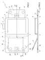
figure 1 is a diagrammatic and perspective view of a case for a computer tablet made in accordance with the present invention; -
figure 2 is a diagrammatic and perspective view of a variant of the case infigure 1 ; -
figure 3 is a diagrammatic and sectional view of the case, according to line III-III infigure 2 ; -
figure 4 is a diagrammatic and sectional view of the case infigure 1 , coupled to a headrest of a vehicle seat; -
figure 5 is a diagrammatic and sectional view of the case infigure 2 , coupled to a headrest of a vehicle seat; -
figure 6 is a diagrammatic view of the headrest infigures 4 and 5 , without case; and -
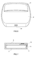
figure 7 is a diagrammatic and sectional view of the case infigure 1 or infigure 2 , uncoupled from the headrest infigure 6 . -
Numeral 1 infigure 1 indicates acase 1 as a whole, for a computer tablet T. -
Case 1 is shaped as a book and comprises arear cover 2, which is provided with ahousing pocket 3 to house the computer tablet (T); thehousing pocket 3 has an access opening through which the computer tablet T may be easily inserted and extracted. Thehousing pocket 3 also comprises aholding flap 4 which is arranged at the access opening and serves to hold the computer tablet T in thehousing pocket 3. Theholding flap 4 is provided with afixing element 5 which mechanically fixes theholding flap 4 to therear cover 2 so as to prevent undesired movements of theholding flap 4; according to a preferred embodiment, thefixing element 5, comprises a Velcro, but alternatively, thefixing element 5 could comprise a snap button or a magnet. -
Case 1, shown infigure 1 , is also provided with afront cover 6, which is connected to therear cover 2 by means of ahinge 7 for rotating with respect to therear cover 2. Thefront cover 6 is provided with twoholding elements 8 which preferably comprise magnets, but may also be replaced by snap buttons or by Velcro. Thefront cover 6 also has a throughcoupling hole 9. - According to the first embodiment shown in
figure 1 ,case 1 is provided with alocking element 10 which is hinged to therear cover 2 by means of ahinge 11 which is parallel to hinge 7, to allow a rotation with respect to therear cover 2. According to the preferred embodiment shown in the accompanying drawings, thelocking element 10 is "C"-shaped, i.e. it has a middle through hole which forms the heart of the "C". Connected to a lower surface of thelocking element 10 is a coupler 12 (shown infigure 4 ), which is engaged in thecoupling hole 9. According to a preferred embodiment, bothcoupler 12 and thecorresponding coupling hole 9 are rectangular in shape. -
Coupler 12 is a hook that is hook-shaped (i.e. folded back on itself) and "L"-shaped (as clearly shown infigure 3 , in which the "L" shape ofcoupler 12 is apparent). As shown infigures 4 and 5 , thecoupling hole 9 is a through coupling hole and is adapted to allow, in use, thecoupler 12 to pass through thecoupling hole 9; in other words, the throughcoupling hole 9 is (slightly) larger thancoupler 12 and therefore coupler 12 passes through the throughcoupling hole 9. Whencoupler 12 is inserted into the coupling hole 9 (as shown infigure 4 ), an initial part ofcoupler 12, which projects upwards (i.e. perpendicular) from the lower surface of thelocking element 10, is in the coupling hole 9 (possibly touching an inner surface of the coupling hole 9), while a final part ofcoupler 12, which is perpendicular to the initial part, is outside thecoupling hole 9 and rests on a surface of thefront cover 6 opposite to thelocking element 10. - The
locking element 10 is also provided with a pushingflap 13, which has an inner edge, which is integral with thelocking element 10, and an outer edge, which projects from thelocking element 10 and is arranged in an empty space delimited by the "C" shape of thelocking element 10. Arranged inside thelocking element 10 is areinforcement metal sheet 14, which directly supportscoupler 12 and is fixed to the inner edge of the pushingflap 13. - The
locking element 10 compriseholding elements 15, preferably magnets (but they may also be replaced by snap buttons or by Velcro), which are coupled to theholding elements 8 of thefront cover 6 with a predetermined holding force, when thelocking element 10 overlaps thefront cover 6. - According to a preferred embodiment, the
holding elements 8 of thefront cover 6 are positioned, with respect to theelements 15 of thelocking element 10, in such a way that the coupling between theholding elements 8 of thefront cover 6 and theholding elements 15 of thelocking element 10pushes coupler 12 supported by thelocking element 10 towards a position in which it engages thecoupling hole 9 more (i.e. in order to disengagecoupler 12 from thecoupling hole 9, there is a need to overcome the force of magnetic attraction generated between theholding elements 8, 15). -
Figure 2 shows a different embodiment ofcase 1, which differs in that thefront cover 6 is provided with afixed panel 16 and with amobile panel 17 which is smaller than thefixed panel 16, is arranged inside thefixed panel 16, and is hinged to thefixed panel 16 by means of a hinge 18 (normally comprising reinforced stitching). In this embodiment, thecoupling hole 9 is obtained in a through manner only through themobile panel 17 of thefront cover 6 and therefore is not visible from the outside of thefront cover 6. Furthermore, thefront cover 6 is provided with tworecesses 19 which are not through recesses, are arranged at opposite sides of themobile panel 17 and are adapted to facilitate the lifting of themobile panel 17 with respect to the fixedpanel 16. Themobile panel 17 is provided with twoholding elements 20, preferably magnets (but they may also be replaced by snap buttons or by Velcro). In particular, and as clearly shown infigure 3 , thefixed panel 16 supports theholding elements 8, while themobile panel 17 supports theholding elements 20; thereby, the force of magnetic attraction generated between theholding elements fixed panel 16 in contact with themobile panel 17. Furthermore, theholding elements 20 of themobile panel 17 interact with theholding elements 15 of thelocking element 10 when thelocking element 10 overlaps thefront cover 6. - As shown in
figure 5 , whencoupler 12 is inserted into thecoupling hole 9, the initial part ofcoupler 12, which projects upwards (i.e. perpendicular) from the lower surface of thelocking element 10, is in the coupling hole 9 (possibly touching an inner surface of the coupling hole 9), while the final part ofcoupler 12, which is perpendicular to the initial part, is outside thecoupling hole 9 and rests on a surface of themobile panel 17 of thefront cover 6 opposite to thelocking element 10. - According to a preferred embodiment, the
holding elements 20 of themobile panel 17 of thefront cover 6 are positioned, with respect to theelements 15 of thelocking element 10, in such a way that the coupling between theholding elements 20 of themobile panel 17 of thefront cover 6 and theholding elements 15 of thelocking element 10pushes coupler 12 supported by thelocking element 10 towards a position in which it engages thecoupling hole 9 more (i.e. in order to disengagecoupler 12 from thecoupling hole 9, there is a need to overcome the force of magnetic attraction generated between theholding elements 20 and 15). - According to a preferred embodiment, the
mobile panel 17 comprises, on the inside, a sheet of pressed cardboard (commercially known as "regenerated leather") and, in the area close to thecoupling hole 9, is stiffened by a reinforcement metal sheet 22 (the same type of reinforcement metal sheet is normally arranged around thecoupling hole 9 also in the embodiment shown infigure 1 ). - With reference to what is shown in
figure 4 , below is a description of the method forcoupling case 1 shown infigure 1 , to a rear wall of a vehicle seat and in particular, to a rear wall of a headrest P of the seat which is provided with a holding ring 23 (better shown infigure 6 ). -
Case 1 is connected to headrest P by means of inserting thefront cover 6 into theholding ring 23, from the bottom; alternatively, thefront cover 6 could be inserted into theholding ring 23 from the top. Then, therear cover 2 is rotated by 180° aroundhinge 7 and with respect to thefront cover 6, so as to lay therear cover 2 against the front cover 6 (leaving thehousing pocket 3 visible) and hence pinch theholding ring 23 of headrest P between the twocovers locking element 10 is rotated by 180° aroundhinge 11 and with respect to therear cover 2, so as to bringcoupler 12 to thecoupling hole 9 obtained in thefront cover 6. Finally,coupler 12 is inserted into thecoupling hole 9 to establish a stable mechanical connection between the twocovers holding elements 15 of thelocking element 10 couple magnetically to theholding elements 8 of thefront cover 6 to holdcoupler 12 in thecoupling hole 9 with greater force. - With reference to what is shown in
figure 5 , below is a description of the method forcoupling case 1 shown infigure 2 , to a rear wall of a vehicle seat and in particular, to a rear wall of a headrest P of the seat which is provided with a holding ring 23 (better shown infigure 6 ). -
Case 1 is connected to headrest P by means of inserting thefront cover 6 into theholding ring 23, from the bottom of the mobile panel 17 (alternatively, themobile panel 17 of thefront cover 6 could be inserted into theholding ring 23 from the top); thereby, theholding ring 23 is interposed between themobile panel 17 and thefixed panel 16 of thefront cover 6 and therefore theholding ring 23 is pinched between themobile panel 17 and thefixed panel 16 of thefront cover 6. Then, therear cover 2 is rotated by 180° aroundhinge 7 and with respect to thefront cover 6, so as to lay therear cover 2 against the front cover 6 (leaving thehousing pocket 3 visible). At this point, thelocking element 10 is rotated by 180° aroundhinge 11 and with respect to therear cover 2, so as to bringcoupler 12 to thecoupling hole 9 obtained in themobile panel 17 of thefront cover 6. Finally,coupler 12 is inserted into thecoupling hole 9 to establish a stable mechanical connection between the twocovers holding elements 15 of thelocking element 10 couple magnetically to theholding elements 20 of themobile panel 17 of thefront cover 6 to holdcoupler 12 in thecoupling hole 9 with greater force. -
Figure 6 shows headrest P of the seat of a car, withoutcase 1. According to a preferred embodiment, headrest P is provided with a "USB"port 24 for recharging the battery of the computer tablet T (and possibly for a data connection between the computer tablet T and the infotelematic system of the car); preferably the "USB"port 24 is arranged below the holdingring 23 in a position which is relatively hidden from sight. - As shown in
figure 7 , whencase 1 is uncoupled from headrest P,case 1 becomes a common case which surrounds and protects the computer tablet T and has the shape and sizes of a standard case. In particular, whencase 1 is uncoupled from headrest P, the lockingelement 10 is rotated by 180° aroundhinge 11 to be positioned above thehousing pocket 3 and therefore thefront cover 6 is rotated by 180° aroundhinge 7 and with respect to therear cover 2, so as to be positioned above the locking element 10 (in this position, thefront cover 6 covers and protects the computer tablet T). Finally,coupler 12 is inserted into thecoupling hole 9 to establish a stable mechanical connection between the twocovers elements 15 of the lockingelement 10 couple magnetically to the holdingelements 20 of themobile panel 17 of the front cover 6 (or, alternatively, to the holdingelements 8 of the front cover 6) to holdcoupler 12 in thecoupling hole 9. - In the embodiment shown in the accompanying drawings,
case 1 couples to headrest P of the seat by means of the holdingring 23; obviously, the holdingring 23 could be arranged in a different position of the rear wall of the seat (e.g. in the seat arranged below headrest P). - The above-described
case 1 has various advantages. - Firstly,
case 1 described above allows an extremely stable, sturdy and reliable mechanical coupling to be achieved with headrest P, and therefore ensures that the computer tablet T does not uncouple in undesired and damaging manner from headrest P in the case of impact. In other words,case 1 described above easily overcomes all impact tests to which a vehicle is subjected to obtain road type approval, because under all conditions of impact, it allows the undesired uncoupling from headrest P to be avoided with extreme safety. In particular,case 1 described above allows an integral mechanical connection with headrest P (which is very important in terms of safety), but at the same time, when desired,case 1 may be removed from headrest P to be used as a common, easily transportable case. - Furthermore,
case 1 described above is for all intents and purposes similar to a standard case and therefore it may be easily used, also when uncoupled from headrest P; in other words,case 1 described above does not differ significantly (i.e. in shape and sizes) from a standard case and therefore it may be easily used, also when uncoupled from headrest P.
Claims (15)
- A case (1) for an electronic device (T), which is shaped as a book and comprises:a rear cover (2), which is provided with a housing pocket (3) to house the electronic device (T);a front cover (6), which is hinged to the rear cover (2) by means of a first hinge (7); anda locking element (10), which is hinged to the rear cover (2) by means of a second hinge (11) opposite to the first hinge (7), has an upper wall and a lower wall, which are parallel and opposite to one another, and is equipped with a coupler (12) which projects from the lower wall of the locking element (10); andwherein the front cover (6) has a coupling hole (9), which is arranged in correspondence to the coupler (12), when the locking element (10) overlaps the front cover (6), and is suited to receive, on the inside, the coupler (12);the case (1) is characterized in that:the coupler (12) is a hook that is hook-shaped and "L"-shaped; andthe coupling hole (9) is a through coupling hole and is suited to allow, in use, the coupler (12) to pass through the coupling hole (9).
- A case (1) according to claim 1, wherein the front cover (6) comprises a fixed panel (16) and a mobile panel (17), which is hinged to the fixed panel (16) by means of a third hinge (18) and has the coupling hole (9).
- A case (1) according to claim 2, wherein the fixed panel (16) and the mobile panel (17) comprise respective holding elements (8, 20), which are coupled to one another with a predetermined holding force, so as to hold the two panels (16, 17) in contact with one another.
- A case (1) according to claim 3, wherein the holding elements are comprised of magnets.
- A case (1) according to claim 2, 3 or 4, wherein the fixed panel (16) of the front cover (6) is provided with two recesses (19), which are arranged on opposite sides of the mobile panel (17).
- A case (1) according to any of the claims from 1 to 5, wherein the housing pocket (3) of the electronic device (T) is provided with a holding flap (4).
- A case (1) according to any of the claims from 1 to 6, wherein the locking element (10) is "C"-shaped and is provided with a pushing flap (13), which has an inner edge, which is integral to the locking element (10), and an outer edge, which projects from the locking element (10) and is arranged in an empty space delimited by the "C" shape of the locking element (10).
- A case (1) according to claim 7, wherein the locking element (10) comprises, on the inside, a reinforcement metal sheet (14), which directly supports the coupler (12) and is fixed to the inner edge of the pushing flap (13).
- A case (1) according to any of the claims from 1 to 8, wherein the front cover (6) and the locking element (10) comprise respective holding elements (8, 15, 20), which are coupled to one another with a predetermined holding force, when the locking element (10) overlaps the front cover (6).
- A case (1) according to claim 9, wherein the holding elements are comprised of magnets.
- A case (1) according to claim 10, wherein the magnets of the front cover (6) are positioned, with respect to the magnets of the locking element (10), in such a way that the magnetic coupling between the magnets of the front cover (6) and the magnets of the locking element (10) pushes the coupler (12) supported by the locking element (10) towards a position in which it engages more the coupling hole (9).
- A case (1) according to any of the claims from 1 to 11, wherein the front cover (6) is provided with a reinforcement metal sheet (22), which is arranged around the coupling hole (9).
- A case (1) according to any of the claims from 1 to 12, wherein, when the coupler 12 is inserted in the coupling hole (9), an initial part of the coupler (12), which projects upwards from the lower surface of the locking element (10), is in the coupling hole (9) and a final part of the coupler (12), which is perpendicular to the initial part, is outside the coupling hole (9) and rests on a surface of the front cover (6) opposite to the locking element (10).
- A method to couple a rear wall of a seat to a case (1) for an electronic device (T) of the type claimed in any of the claims from 1 to 13 and comprising the steps of:inserting the front cover (6) into a holding ring (23) of the seat;rotating the rear cover (2) around the first hinge (7), so as to lay the rear cover (2) against the front cover (6);rotating the locking element (10) around the second hinge (11), so as to bring the coupler (12) in correspondence to the coupling hole (9); andinserting the coupler (12) into the coupling hole (9), so as to cause the coupler (12) to pass through the coupling hole (9) and therefore to establish a stable mechanical connection between the two covers (2, 6).
- A method according to claim 14, wherein:the front cover (6) comprises a fixed panel (16) and a mobile panel (17), which is hinged to the fixed panel (16) by means of a third hinge (18) and has the coupling hole (9); andthe step of inserting the front cover (6) into the holding ring (23) comprises inserting, into the holding ring (23), only the mobile panel (17) of the front cover (6), so as to interpose the holding ring (23) between the mobile panel (17) and the fixed panel (16) of the front cover (6).
Applications Claiming Priority (1)
| Application Number | Priority Date | Filing Date | Title |
|---|---|---|---|
| IT000240A ITBO20130240A1 (en) | 2013-05-22 | 2013-05-22 | HOUSING FOR AN ELECTRONIC DEVICE WITH A SEAT ATTACHMENT SYSTEM |
Publications (3)
| Publication Number | Publication Date |
|---|---|
| EP2805640A2 true EP2805640A2 (en) | 2014-11-26 |
| EP2805640A3 EP2805640A3 (en) | 2015-08-05 |
| EP2805640B1 EP2805640B1 (en) | 2018-10-31 |
Family
ID=48808433
Family Applications (1)
| Application Number | Title | Priority Date | Filing Date |
|---|---|---|---|
| EP14169451.3A Active EP2805640B1 (en) | 2013-05-22 | 2014-05-22 | Case for an electronic device with a coupling system to be coupled to a seat |
Country Status (3)
| Country | Link |
|---|---|
| US (1) | US9302808B2 (en) |
| EP (1) | EP2805640B1 (en) |
| IT (1) | ITBO20130240A1 (en) |
Families Citing this family (4)
| Publication number | Priority date | Publication date | Assignee | Title |
|---|---|---|---|---|
| US20150123433A1 (en) * | 2013-11-01 | 2015-05-07 | Astronics Advanced Electronic Systems Corp. | Holder For Personal Electronic Devices |
| USD732046S1 (en) * | 2014-01-22 | 2015-06-16 | Hon Hai Precision Industry Co., Ltd. | Supporting assembly for electronic device |
| USD736778S1 (en) * | 2014-08-01 | 2015-08-18 | Hopkins Manufacturing Corporation | Automotive seat mountable tablet computer holding device |
| KR102053579B1 (en) * | 2019-05-14 | 2019-12-06 | 이민수 | Apparatus for mounting potable device |
Citations (1)
| Publication number | Priority date | Publication date | Assignee | Title |
|---|---|---|---|---|
| US20090073337A1 (en) | 2007-09-10 | 2009-03-19 | Hannspree, Inc. | LCD display with adjustable view-angle structure |
Family Cites Families (8)
| Publication number | Priority date | Publication date | Assignee | Title |
|---|---|---|---|---|
| US5607054A (en) * | 1995-03-14 | 1997-03-04 | Port, Inc. | Folio carrying case for a notebook computer |
| US6216927B1 (en) * | 1998-08-03 | 2001-04-17 | Ronald Meritt | Mounting system for releasably and securely mounting an entertainment accessory within an automobile |
| US6561402B2 (en) * | 2000-05-16 | 2003-05-13 | Black & Decker Inc. | Ambidextrous drill holster |
| US6994236B2 (en) * | 2002-07-27 | 2006-02-07 | Te Hsin Hsu | Monitoring supporting device for attaching to vehicles |
| CN100462258C (en) * | 2005-08-26 | 2009-02-18 | 鸿富锦精密工业(深圳)有限公司 | Electronic entertainment equipment bag |
| US7772504B1 (en) * | 2008-09-16 | 2010-08-10 | Richard Tashjian | Laptop shield carrying case and cellular shield holster |
| US20120308164A1 (en) * | 2011-06-03 | 2012-12-06 | Mamie Slaughter Hudson | Accessory Carrier for Personal Digital Device |
| CN204284838U (en) * | 2011-12-22 | 2015-04-22 | 拓乐组织解决方案公司 | Protective cases for electronic devices |
-
2013
- 2013-05-22 IT IT000240A patent/ITBO20130240A1/en unknown
-
2014
- 2014-05-21 US US14/284,081 patent/US9302808B2/en active Active
- 2014-05-22 EP EP14169451.3A patent/EP2805640B1/en active Active
Patent Citations (1)
| Publication number | Priority date | Publication date | Assignee | Title |
|---|---|---|---|---|
| US20090073337A1 (en) | 2007-09-10 | 2009-03-19 | Hannspree, Inc. | LCD display with adjustable view-angle structure |
Also Published As
| Publication number | Publication date |
|---|---|
| US9302808B2 (en) | 2016-04-05 |
| ITBO20130240A1 (en) | 2014-11-23 |
| US20140346167A1 (en) | 2014-11-27 |
| EP2805640A3 (en) | 2015-08-05 |
| EP2805640B1 (en) | 2018-10-31 |
Similar Documents
| Publication | Publication Date | Title |
|---|---|---|
| EP2805640B1 (en) | Case for an electronic device with a coupling system to be coupled to a seat | |
| CN203759583U (en) | Protective shell used for electronic device | |
| US8922354B2 (en) | External haptic generator for portable electronic devices | |
| US9743729B2 (en) | Protection cover | |
| KR101936918B1 (en) | Virtual reality headset | |
| CN106103194B (en) | For running the method, reception device and the automobile with reception device of reception device | |
| EP2618690B1 (en) | A case for enclosing a personal electronic device and card | |
| US9960800B2 (en) | Cradle assembly for vehicle capable of connecting with mobile terminal | |
| US20150129724A1 (en) | Support device, attachment, and method of supporting electronic device | |
| CN104442597B (en) | For fixing the holding meanss of electrical device in a motor vehicle | |
| KR20160023533A (en) | Cell phone case with integral resilient suspension hook | |
| KR20180021395A (en) | Attachment feature for accessory device | |
| KR101708690B1 (en) | Cradle Assembly available to connect with Portable Device for Vehicles | |
| US20160320799A1 (en) | Tablet terminal attachment | |
| US10098430B2 (en) | Protection cover | |
| US9809141B2 (en) | Storage compartment comprising a foldable holder element | |
| US20180334261A1 (en) | Touch screen tablet personal computer holder for a vehicle including general aviation aircraft | |
| US12451919B2 (en) | Modular customizable ruggedized protective case with detachable sidewall for mobile device | |
| CN109955795B (en) | Vehicle fixed structure | |
| ES2903265T3 (en) | Locking strip for a digital device in a chassis | |
| US20150258941A1 (en) | Handheld Electronic Device Support and Electrical Connector | |
| KR20090117099A (en) | Car Mount High Pass Terminal | |
| US20190202369A1 (en) | Computer tablet case with rear mounting | |
| US20050259071A1 (en) | Secure enclosure for portable electronic display device operated by push buttons | |
| KR20160098008A (en) | Cradle for mobile phone |
Legal Events
| Date | Code | Title | Description |
|---|---|---|---|
| PUAI | Public reference made under article 153(3) epc to a published international application that has entered the european phase |
Free format text: ORIGINAL CODE: 0009012 |
|
| 17P | Request for examination filed |
Effective date: 20140522 |
|
| AK | Designated contracting states |
Kind code of ref document: A2 Designated state(s): AL AT BE BG CH CY CZ DE DK EE ES FI FR GB GR HR HU IE IS IT LI LT LU LV MC MK MT NL NO PL PT RO RS SE SI SK SM TR |
|
| AX | Request for extension of the european patent |
Extension state: BA ME |
|
| PUAL | Search report despatched |
Free format text: ORIGINAL CODE: 0009013 |
|
| AK | Designated contracting states |
Kind code of ref document: A3 Designated state(s): AL AT BE BG CH CY CZ DE DK EE ES FI FR GB GR HR HU IE IS IT LI LT LU LV MC MK MT NL NO PL PT RO RS SE SI SK SM TR |
|
| AX | Request for extension of the european patent |
Extension state: BA ME |
|
| RIC1 | Information provided on ipc code assigned before grant |
Ipc: A45C 11/00 20060101AFI20150702BHEP Ipc: B60R 11/02 20060101ALI20150702BHEP |
|
| R17P | Request for examination filed (corrected) |
Effective date: 20160204 |
|
| GRAP | Despatch of communication of intention to grant a patent |
Free format text: ORIGINAL CODE: EPIDOSNIGR1 |
|
| STAA | Information on the status of an ep patent application or granted ep patent |
Free format text: STATUS: GRANT OF PATENT IS INTENDED |
|
| INTG | Intention to grant announced |
Effective date: 20180517 |
|
| GRAS | Grant fee paid |
Free format text: ORIGINAL CODE: EPIDOSNIGR3 |
|
| GRAA | (expected) grant |
Free format text: ORIGINAL CODE: 0009210 |
|
| STAA | Information on the status of an ep patent application or granted ep patent |
Free format text: STATUS: THE PATENT HAS BEEN GRANTED |
|
| AK | Designated contracting states |
Kind code of ref document: B1 Designated state(s): AL AT BE BG CH CY CZ DE DK EE ES FI FR GB GR HR HU IE IS IT LI LT LU LV MC MK MT NL NO PL PT RO RS SE SI SK SM TR |
|
| REG | Reference to a national code |
Ref country code: CH Ref legal event code: EP Ref country code: GB Ref legal event code: FG4D |
|
| REG | Reference to a national code |
Ref country code: AT Ref legal event code: REF Ref document number: 1058344 Country of ref document: AT Kind code of ref document: T Effective date: 20181115 |
|
| REG | Reference to a national code |
Ref country code: DE Ref legal event code: R096 Ref document number: 602014034973 Country of ref document: DE |
|
| REG | Reference to a national code |
Ref country code: IE Ref legal event code: FG4D |
|
| REG | Reference to a national code |
Ref country code: NL Ref legal event code: MP Effective date: 20181031 |
|
| REG | Reference to a national code |
Ref country code: LT Ref legal event code: MG4D |
|
| REG | Reference to a national code |
Ref country code: AT Ref legal event code: MK05 Ref document number: 1058344 Country of ref document: AT Kind code of ref document: T Effective date: 20181031 |
|
| PG25 | Lapsed in a contracting state [announced via postgrant information from national office to epo] |
Ref country code: FI Free format text: LAPSE BECAUSE OF FAILURE TO SUBMIT A TRANSLATION OF THE DESCRIPTION OR TO PAY THE FEE WITHIN THE PRESCRIBED TIME-LIMIT Effective date: 20181031 Ref country code: IS Free format text: LAPSE BECAUSE OF FAILURE TO SUBMIT A TRANSLATION OF THE DESCRIPTION OR TO PAY THE FEE WITHIN THE PRESCRIBED TIME-LIMIT Effective date: 20190228 Ref country code: LV Free format text: LAPSE BECAUSE OF FAILURE TO SUBMIT A TRANSLATION OF THE DESCRIPTION OR TO PAY THE FEE WITHIN THE PRESCRIBED TIME-LIMIT Effective date: 20181031 Ref country code: AT Free format text: LAPSE BECAUSE OF FAILURE TO SUBMIT A TRANSLATION OF THE DESCRIPTION OR TO PAY THE FEE WITHIN THE PRESCRIBED TIME-LIMIT Effective date: 20181031 Ref country code: NO Free format text: LAPSE BECAUSE OF FAILURE TO SUBMIT A TRANSLATION OF THE DESCRIPTION OR TO PAY THE FEE WITHIN THE PRESCRIBED TIME-LIMIT Effective date: 20190131 Ref country code: HR Free format text: LAPSE BECAUSE OF FAILURE TO SUBMIT A TRANSLATION OF THE DESCRIPTION OR TO PAY THE FEE WITHIN THE PRESCRIBED TIME-LIMIT Effective date: 20181031 Ref country code: BG Free format text: LAPSE BECAUSE OF FAILURE TO SUBMIT A TRANSLATION OF THE DESCRIPTION OR TO PAY THE FEE WITHIN THE PRESCRIBED TIME-LIMIT Effective date: 20190131 Ref country code: PL Free format text: LAPSE BECAUSE OF FAILURE TO SUBMIT A TRANSLATION OF THE DESCRIPTION OR TO PAY THE FEE WITHIN THE PRESCRIBED TIME-LIMIT Effective date: 20181031 Ref country code: ES Free format text: LAPSE BECAUSE OF FAILURE TO SUBMIT A TRANSLATION OF THE DESCRIPTION OR TO PAY THE FEE WITHIN THE PRESCRIBED TIME-LIMIT Effective date: 20181031 Ref country code: LT Free format text: LAPSE BECAUSE OF FAILURE TO SUBMIT A TRANSLATION OF THE DESCRIPTION OR TO PAY THE FEE WITHIN THE PRESCRIBED TIME-LIMIT Effective date: 20181031 |
|
| PG25 | Lapsed in a contracting state [announced via postgrant information from national office to epo] |
Ref country code: NL Free format text: LAPSE BECAUSE OF FAILURE TO SUBMIT A TRANSLATION OF THE DESCRIPTION OR TO PAY THE FEE WITHIN THE PRESCRIBED TIME-LIMIT Effective date: 20181031 Ref country code: PT Free format text: LAPSE BECAUSE OF FAILURE TO SUBMIT A TRANSLATION OF THE DESCRIPTION OR TO PAY THE FEE WITHIN THE PRESCRIBED TIME-LIMIT Effective date: 20190301 Ref country code: SE Free format text: LAPSE BECAUSE OF FAILURE TO SUBMIT A TRANSLATION OF THE DESCRIPTION OR TO PAY THE FEE WITHIN THE PRESCRIBED TIME-LIMIT Effective date: 20181031 Ref country code: AL Free format text: LAPSE BECAUSE OF FAILURE TO SUBMIT A TRANSLATION OF THE DESCRIPTION OR TO PAY THE FEE WITHIN THE PRESCRIBED TIME-LIMIT Effective date: 20181031 Ref country code: GR Free format text: LAPSE BECAUSE OF FAILURE TO SUBMIT A TRANSLATION OF THE DESCRIPTION OR TO PAY THE FEE WITHIN THE PRESCRIBED TIME-LIMIT Effective date: 20190201 Ref country code: RS Free format text: LAPSE BECAUSE OF FAILURE TO SUBMIT A TRANSLATION OF THE DESCRIPTION OR TO PAY THE FEE WITHIN THE PRESCRIBED TIME-LIMIT Effective date: 20181031 |
|
| PG25 | Lapsed in a contracting state [announced via postgrant information from national office to epo] |
Ref country code: CZ Free format text: LAPSE BECAUSE OF FAILURE TO SUBMIT A TRANSLATION OF THE DESCRIPTION OR TO PAY THE FEE WITHIN THE PRESCRIBED TIME-LIMIT Effective date: 20181031 Ref country code: DK Free format text: LAPSE BECAUSE OF FAILURE TO SUBMIT A TRANSLATION OF THE DESCRIPTION OR TO PAY THE FEE WITHIN THE PRESCRIBED TIME-LIMIT Effective date: 20181031 |
|
| REG | Reference to a national code |
Ref country code: DE Ref legal event code: R097 Ref document number: 602014034973 Country of ref document: DE |
|
| PG25 | Lapsed in a contracting state [announced via postgrant information from national office to epo] |
Ref country code: EE Free format text: LAPSE BECAUSE OF FAILURE TO SUBMIT A TRANSLATION OF THE DESCRIPTION OR TO PAY THE FEE WITHIN THE PRESCRIBED TIME-LIMIT Effective date: 20181031 Ref country code: SM Free format text: LAPSE BECAUSE OF FAILURE TO SUBMIT A TRANSLATION OF THE DESCRIPTION OR TO PAY THE FEE WITHIN THE PRESCRIBED TIME-LIMIT Effective date: 20181031 Ref country code: RO Free format text: LAPSE BECAUSE OF FAILURE TO SUBMIT A TRANSLATION OF THE DESCRIPTION OR TO PAY THE FEE WITHIN THE PRESCRIBED TIME-LIMIT Effective date: 20181031 Ref country code: SK Free format text: LAPSE BECAUSE OF FAILURE TO SUBMIT A TRANSLATION OF THE DESCRIPTION OR TO PAY THE FEE WITHIN THE PRESCRIBED TIME-LIMIT Effective date: 20181031 |
|
| PLBE | No opposition filed within time limit |
Free format text: ORIGINAL CODE: 0009261 |
|
| STAA | Information on the status of an ep patent application or granted ep patent |
Free format text: STATUS: NO OPPOSITION FILED WITHIN TIME LIMIT |
|
| 26N | No opposition filed |
Effective date: 20190801 |
|
| PG25 | Lapsed in a contracting state [announced via postgrant information from national office to epo] |
Ref country code: SI Free format text: LAPSE BECAUSE OF FAILURE TO SUBMIT A TRANSLATION OF THE DESCRIPTION OR TO PAY THE FEE WITHIN THE PRESCRIBED TIME-LIMIT Effective date: 20181031 |
|
| REG | Reference to a national code |
Ref country code: CH Ref legal event code: PL |
|
| PG25 | Lapsed in a contracting state [announced via postgrant information from national office to epo] |
Ref country code: CH Free format text: LAPSE BECAUSE OF NON-PAYMENT OF DUE FEES Effective date: 20190531 Ref country code: LI Free format text: LAPSE BECAUSE OF NON-PAYMENT OF DUE FEES Effective date: 20190531 Ref country code: MC Free format text: LAPSE BECAUSE OF FAILURE TO SUBMIT A TRANSLATION OF THE DESCRIPTION OR TO PAY THE FEE WITHIN THE PRESCRIBED TIME-LIMIT Effective date: 20181031 |
|
| REG | Reference to a national code |
Ref country code: BE Ref legal event code: MM Effective date: 20190531 |
|
| PG25 | Lapsed in a contracting state [announced via postgrant information from national office to epo] |
Ref country code: LU Free format text: LAPSE BECAUSE OF NON-PAYMENT OF DUE FEES Effective date: 20190522 |
|
| PG25 | Lapsed in a contracting state [announced via postgrant information from national office to epo] |
Ref country code: TR Free format text: LAPSE BECAUSE OF FAILURE TO SUBMIT A TRANSLATION OF THE DESCRIPTION OR TO PAY THE FEE WITHIN THE PRESCRIBED TIME-LIMIT Effective date: 20181031 |
|
| PG25 | Lapsed in a contracting state [announced via postgrant information from national office to epo] |
Ref country code: IE Free format text: LAPSE BECAUSE OF NON-PAYMENT OF DUE FEES Effective date: 20190522 |
|
| PG25 | Lapsed in a contracting state [announced via postgrant information from national office to epo] |
Ref country code: BE Free format text: LAPSE BECAUSE OF NON-PAYMENT OF DUE FEES Effective date: 20190531 |
|
| PG25 | Lapsed in a contracting state [announced via postgrant information from national office to epo] |
Ref country code: FR Free format text: LAPSE BECAUSE OF NON-PAYMENT OF DUE FEES Effective date: 20190531 |
|
| PG25 | Lapsed in a contracting state [announced via postgrant information from national office to epo] |
Ref country code: CY Free format text: LAPSE BECAUSE OF FAILURE TO SUBMIT A TRANSLATION OF THE DESCRIPTION OR TO PAY THE FEE WITHIN THE PRESCRIBED TIME-LIMIT Effective date: 20181031 |
|
| PG25 | Lapsed in a contracting state [announced via postgrant information from national office to epo] |
Ref country code: HU Free format text: LAPSE BECAUSE OF FAILURE TO SUBMIT A TRANSLATION OF THE DESCRIPTION OR TO PAY THE FEE WITHIN THE PRESCRIBED TIME-LIMIT; INVALID AB INITIO Effective date: 20140522 Ref country code: MT Free format text: LAPSE BECAUSE OF FAILURE TO SUBMIT A TRANSLATION OF THE DESCRIPTION OR TO PAY THE FEE WITHIN THE PRESCRIBED TIME-LIMIT Effective date: 20181031 |
|
| PG25 | Lapsed in a contracting state [announced via postgrant information from national office to epo] |
Ref country code: MK Free format text: LAPSE BECAUSE OF FAILURE TO SUBMIT A TRANSLATION OF THE DESCRIPTION OR TO PAY THE FEE WITHIN THE PRESCRIBED TIME-LIMIT Effective date: 20181031 |
|
| P01 | Opt-out of the competence of the unified patent court (upc) registered |
Effective date: 20230525 |
|
| PGFP | Annual fee paid to national office [announced via postgrant information from national office to epo] |
Ref country code: DE Payment date: 20250528 Year of fee payment: 12 |
|
| PGFP | Annual fee paid to national office [announced via postgrant information from national office to epo] |
Ref country code: IT Payment date: 20250509 Year of fee payment: 12 |
|
| PGFP | Annual fee paid to national office [announced via postgrant information from national office to epo] |
Ref country code: GB Payment date: 20260304 Year of fee payment: 13 |