EP2805584B1 - Methode et appareil pour la gestion d'un réseau d'éclairage d'extérieur - Google Patents
Methode et appareil pour la gestion d'un réseau d'éclairage d'extérieur Download PDFInfo
- Publication number
- EP2805584B1 EP2805584B1 EP13706728.6A EP13706728A EP2805584B1 EP 2805584 B1 EP2805584 B1 EP 2805584B1 EP 13706728 A EP13706728 A EP 13706728A EP 2805584 B1 EP2805584 B1 EP 2805584B1
- Authority
- EP
- European Patent Office
- Prior art keywords
- outdoor lighting
- management system
- lighting network
- vendor
- central management
- Prior art date
- Legal status (The legal status is an assumption and is not a legal conclusion. Google has not performed a legal analysis and makes no representation as to the accuracy of the status listed.)
- Active
Links
- 238000000034 method Methods 0.000 title claims description 37
- 238000007726 management method Methods 0.000 claims description 175
- 238000004891 communication Methods 0.000 claims description 94
- 230000004044 response Effects 0.000 claims description 15
- 230000008859 change Effects 0.000 claims description 14
- 238000005259 measurement Methods 0.000 claims description 14
- 238000012790 confirmation Methods 0.000 claims description 6
- 238000013024 troubleshooting Methods 0.000 claims description 2
- 230000006870 function Effects 0.000 description 9
- 239000000463 material Substances 0.000 description 5
- 230000008901 benefit Effects 0.000 description 4
- 230000001419 dependent effect Effects 0.000 description 4
- 230000006399 behavior Effects 0.000 description 3
- 238000012508 change request Methods 0.000 description 3
- 239000000835 fiber Substances 0.000 description 3
- 238000009434 installation Methods 0.000 description 3
- 230000005855 radiation Effects 0.000 description 3
- 238000013519 translation Methods 0.000 description 3
- 238000004590 computer program Methods 0.000 description 2
- 230000010354 integration Effects 0.000 description 2
- 229920000642 polymer Polymers 0.000 description 2
- 238000001228 spectrum Methods 0.000 description 2
- OKTJSMMVPCPJKN-UHFFFAOYSA-N Carbon Chemical compound [C] OKTJSMMVPCPJKN-UHFFFAOYSA-N 0.000 description 1
- DGAQECJNVWCQMB-PUAWFVPOSA-M Ilexoside XXIX Chemical compound C[C@@H]1CC[C@@]2(CC[C@@]3(C(=CC[C@H]4[C@]3(CC[C@@H]5[C@@]4(CC[C@@H](C5(C)C)OS(=O)(=O)[O-])C)C)[C@@H]2[C@]1(C)O)C)C(=O)O[C@H]6[C@@H]([C@H]([C@@H]([C@H](O6)CO)O)O)O.[Na+] DGAQECJNVWCQMB-PUAWFVPOSA-M 0.000 description 1
- 238000003491 array Methods 0.000 description 1
- 230000009286 beneficial effect Effects 0.000 description 1
- 229910052799 carbon Inorganic materials 0.000 description 1
- 238000013500 data storage Methods 0.000 description 1
- 238000005265 energy consumption Methods 0.000 description 1
- 238000005516 engineering process Methods 0.000 description 1
- 229910052736 halogen Inorganic materials 0.000 description 1
- 150000002367 halogens Chemical class 0.000 description 1
- 230000003993 interaction Effects 0.000 description 1
- 238000012423 maintenance Methods 0.000 description 1
- QSHDDOUJBYECFT-UHFFFAOYSA-N mercury Chemical compound [Hg] QSHDDOUJBYECFT-UHFFFAOYSA-N 0.000 description 1
- 229910001507 metal halide Inorganic materials 0.000 description 1
- 150000005309 metal halides Chemical class 0.000 description 1
- 238000012986 modification Methods 0.000 description 1
- 230000004048 modification Effects 0.000 description 1
- 238000012544 monitoring process Methods 0.000 description 1
- 230000003287 optical effect Effects 0.000 description 1
- 230000000737 periodic effect Effects 0.000 description 1
- 235000019553 satiation Nutrition 0.000 description 1
- 239000004065 semiconductor Substances 0.000 description 1
- 229910052708 sodium Inorganic materials 0.000 description 1
- 239000011734 sodium Substances 0.000 description 1
- 238000012546 transfer Methods 0.000 description 1
- 230000001960 triggered effect Effects 0.000 description 1
Images


Classifications
-
- H—ELECTRICITY
- H05—ELECTRIC TECHNIQUES NOT OTHERWISE PROVIDED FOR
- H05B—ELECTRIC HEATING; ELECTRIC LIGHT SOURCES NOT OTHERWISE PROVIDED FOR; CIRCUIT ARRANGEMENTS FOR ELECTRIC LIGHT SOURCES, IN GENERAL
- H05B47/00—Circuit arrangements for operating light sources in general, i.e. where the type of light source is not relevant
- H05B47/10—Controlling the light source
- H05B47/175—Controlling the light source by remote control
- H05B47/18—Controlling the light source by remote control via data-bus transmission
-
- G—PHYSICS
- G05—CONTROLLING; REGULATING
- G05B—CONTROL OR REGULATING SYSTEMS IN GENERAL; FUNCTIONAL ELEMENTS OF SUCH SYSTEMS; MONITORING OR TESTING ARRANGEMENTS FOR SUCH SYSTEMS OR ELEMENTS
- G05B15/00—Systems controlled by a computer
- G05B15/02—Systems controlled by a computer electric
-
- H—ELECTRICITY
- H05—ELECTRIC TECHNIQUES NOT OTHERWISE PROVIDED FOR
- H05B—ELECTRIC HEATING; ELECTRIC LIGHT SOURCES NOT OTHERWISE PROVIDED FOR; CIRCUIT ARRANGEMENTS FOR ELECTRIC LIGHT SOURCES, IN GENERAL
- H05B47/00—Circuit arrangements for operating light sources in general, i.e. where the type of light source is not relevant
- H05B47/10—Controlling the light source
- H05B47/175—Controlling the light source by remote control
-
- Y—GENERAL TAGGING OF NEW TECHNOLOGICAL DEVELOPMENTS; GENERAL TAGGING OF CROSS-SECTIONAL TECHNOLOGIES SPANNING OVER SEVERAL SECTIONS OF THE IPC; TECHNICAL SUBJECTS COVERED BY FORMER USPC CROSS-REFERENCE ART COLLECTIONS [XRACs] AND DIGESTS
- Y02—TECHNOLOGIES OR APPLICATIONS FOR MITIGATION OR ADAPTATION AGAINST CLIMATE CHANGE
- Y02B—CLIMATE CHANGE MITIGATION TECHNOLOGIES RELATED TO BUILDINGS, e.g. HOUSING, HOUSE APPLIANCES OR RELATED END-USER APPLICATIONS
- Y02B20/00—Energy efficient lighting technologies, e.g. halogen lamps or gas discharge lamps
- Y02B20/72—Energy efficient lighting technologies, e.g. halogen lamps or gas discharge lamps in street lighting
Definitions
- the present invention is directed generally to management of outdoor lighting networks. More particularly, various inventive methods and apparatus disclosed herein relate to integrated customer management of multiple unique lighting networks.
- Lighting units of an OLN may be remotely managed to provide control over lighting behavior (e . g ., scheduling of the on/off times of the lighting units and/or setting dimming levels of the lighting units) and/or to monitor lighting unit characteristics (e . g ., light source status, energy consumption, lighting unit specifications).
- Management of outdoor lighting networks may provide one or more benefits to customers (e . g ., municipalities) such as energy savings, reduced maintenance costs, and/or reduced lighting pollution.
- OLNs often utilize proprietary control and/or communication protocols that are not open to other device suppliers.
- the underlying connectivity technologies used in certain OLN implementations may be standard (e . g ., certain wireless and/or power-line communications standards)
- the control and/or communication protocols are often proprietary. Accordingly, a customer with a plurality of OLNs must either utilize only a single vendor for those OLNs or maintain different systems and procedures to remotely manage the OLNs.
- CMS central management systems
- a central management system for a plurality of wireless lighting networks is disclosed in a White Paper by Jennie Ltd UK entitled “Intelligent street lighting” and published in April 2009 .
- a management system may be provided that includes a single CMS in communication with each of a plurality of multi-vendor outdoor lighting networks, and a plurality of vendor management systems (VMSs), each in communication with one or more of the lighting networks from a single vendor.
- VMSs vendor management systems
- methods may be provided that relate to managing a plurality of multi-vendor outdoor lighting networks and/or to commissioning and configuring a plurality of multi-vendor outdoor lighting networks.
- an outdoor lighting network management system includes a plurality of outdoor lighting networks, a central management system in communication with each of the outdoor lighting networks, and a first vendor management system in communication with a first lighting network of the outdoor lighting networks.
- Each of the outdoor lighting networks includes a plurality of outdoor lighting network devices.
- the central management system sends configuration commands to each of the outdoor lighting networks and receives outdoor lighting network device information from each of the outdoor lighting networks.
- the outdoor lighting network device information includes details of the lighting network devices.
- the configuration commands set a configuration of at least one of the outdoor lighting network devices, and include lighting configuration commands setting light output characteristics of the light sources of the outdoor lighting network devices. Communications between the first lighting network and the first vendor management system commission the first lighting network and are operable to communicate with the first lighting network.
- system further includes a second vendor management system in communication with a second lighting network of the outdoor lighting networks.
- At least a group of the configuration commands sent to the first lighting network is also sent to the first vendor management system and verified by the first vendor management system.
- the lighting configuration commands include at least one of a dimming configuration, a schedule configuration, a measurements configuration, and a color control configuration.
- At least a group of the configuration commands sent to the first lighting network is also sent to the first vendor management system and verified by the first vendor management system prior to altering the configuration of at least one of the outdoor devices of the first lighting network.
- the central management system is in communication with each of the outdoor lighting networks via a central management system protocol stack having a first application layer.
- the first vendor management system is in communication with the first lighting network via a first vendor protocol stack having a second application layer distinct from the first application layer.
- the system further includes a second vendor management system in communication with a second lighting network of the outdoor lighting networks. The second vendor management system is in communication with the second lighting network via a second vendor protocol stack having a third application layer distinct from the first application layer and distinct from the second application layer.
- the first outdoor lighting network is topologically interposed between the central management system and the first vendor management system.
- the first vendor management system is topologically interposed between the central management system and the first outdoor lighting network.
- a method of managing a plurality of outdoor lighting networks includes the steps of: receiving first central management system configuration commands from a central management system; translating the first central management configuration commands to distinct and different first outdoor lighting network configuration commands readable by first devices of the first outdoor lighting network; receiving second central management system configuration commands from the central management system; translating the second central management configuration commands to distinct and different second outdoor lighting network configuration commands readable by second devices of the second outdoor lighting network; receiving first vendor management commands from a first vendor management system readable by the first devices; and receiving second vendor management commands from a second vendor management system readable by the second devices.
- the method further includes the step of receiving device information of the first devices, translating the device information to distinct and different central management system data readable by the central management system, and sending the central management system data to the central management system.
- the method further includes the step of validating the first central management configuration commands.
- an outdoor lighting network management apparatus includes at least one central management system connection.
- the central management system connection receives central management configuration commands from a central management system.
- the apparatus also includes at least one controller operable to translate the central management configuration commands to distinct and different central management directed outdoor lighting network configuration commands.
- the apparatus also includes at least one outdoor lighting network connection sending the central management directed outdoor lighting network configuration commands to at least one outdoor lighting network device.
- the apparatus also includes at least one a vendor management system input.
- the vendor management system input receives vendor management commands from a vendor management system.
- At least some of the vendor management commands direct whether at least some of the central management directed outdoor lighting network configuration commands are sent to the at least one outdoor lighting network device.
- the central management system connection transmits outdoor lighting network device information to the central management system, the outdoor lighting network device information including attributes of the at least one outdoor lighting network device. In some versions of those embodiments the central management system connection transmits outdoor lighting network configuration change confirmation to the central management system, the outdoor lighting network configuration change confirmation sent in response to the at least one outdoor lighting network device changing configuration based on the central management directed outdoor lighting network configuration commands.
- the vendor management commands include at least one of outdoor lighting network commissioning commands, outdoor lighting network management commands, outdoor lighting network troubleshooting commands, and outdoor lighting network security management commands.
- the central management system connection, the outdoor lighting network connection, and the vendor management system input are all at a direct communication lighting network device.
- the central management system connection, the outdoor lighting network connection, and the vendor management system input are all at the vendor management system.
- a method of commissioning and configuring a plurality of multi-vendor outdoor lighting networks may include the steps of: initializing the outdoor lighting network and confirming devices of the outdoor lighting network with a vendor management system; transferring information related to the devices of the outdoor lighting network to the central management system; assigning unique central management system IDs to the devices of the outdoor lighting network; and configuring outdoor lighting devices from the central management system.
- the method may further include the step of validating the central management system initiated configuration of one or more devices of the outdoor lighting network at the vendor management system.
- light source should be understood to refer to any one or more of a variety of radiation sources, including, but not limited to, LED-based sources (e.g., various semiconductor-based structures that emit light in response to current, light emitting polymers, organic light emitting diodes (OLEDs), electroluminescent strips, and the like), incandescent sources (e.g., filament lamps, halogen lamps), fluorescent sources, phosphorescent sources, high-intensity discharge sources (e.g., sodium vapor, mercury vapor, and metal halide lamps), lasers, other types of electroluminescent sources, pyro-luminescent sources (e.g., flames), candle-luminescent sources (e.g., gas mantles, carbon arc radiation sources), photoluminescent sources (e.g., gaseous discharge sources), cathode luminescent sources using electronic satiation, galvano-luminescent sources, crystallo-luminescent sources, kine-luminescent sources, thermo-luminescent sources
- light fixture is used herein to refer to an implementation or arrangement of one or more lighting units in a particular form factor, assembly, or package.
- lighting unit is used herein to refer to an apparatus including one or more light sources of same or different types.
- a given lighting unit may have any one of a variety of mounting arrangements for the light source(s), enclosure/housing arrangements and shapes, and/or electrical and mechanical connection configurations. Additionally, a given lighting unit optionally may be associated with (e.g., include, be coupled to and/or packaged together with) various other components (e.g., control circuitry) relating to the operation of the light source(s).
- LED-based lighting unit refers to a lighting unit that includes one or more LED-based light sources as discussed above, alone or in combination with other non LED-based light sources.
- a “multi-channel” lighting unit refers to an LED-based or non LED-based lighting unit that includes at least two light sources configured to respectively generate different spectrums of radiation, wherein each different source spectrum may be referred to as a "channel" of the multi-channel lighting unit.
- controller is used herein generally to describe various apparatus relating to the operation of one or more light sources.
- a controller can be implemented in numerous ways (e.g., such as with dedicated hardware) to perform various functions discussed herein.
- a "processor” is one example of a controller which employs one or more microprocessors that may be programmed using software (e.g., microcode) to perform various functions discussed herein.
- a controller may be implemented with or without employing a processor, and also may be implemented as a combination of dedicated hardware to perform some functions and a processor (e.g., one or more programmed microprocessors and associated circuitry) to perform other functions. Examples of controller components that may be employed in various embodiments of the present disclosure include, but are not limited to, conventional microprocessors, application specific integrated circuits (ASICs), and field-programmable gate arrays (FPGAs).
- ASICs application specific integrated circuits
- FPGAs field-programmable gate arrays
- a processor or controller may be associated with one or more storage media (generically referred to herein as "memory,” e.g., volatile and non-volatile computer memory such as RAM, PROM, EPROM, and EEPROM, floppy disks, compact disks, optical disks, magnetic tape, etc.).
- the storage media may be encoded with one or more programs that, when executed on one or more processors and/or controllers, perform at least some of the functions discussed herein.
- Various storage media may be fixed within a processor or controller or may be transportable, such that the one or more programs stored thereon can be loaded into a processor or controller so as to implement various aspects of the present invention discussed herein.
- program or “computer program” are used herein in a generic sense to refer to any type of computer code (e.g., software or microcode) that can be employed to program one or more processors or controllers.
- addressable is used herein to refer to a device (e.g., a light source in general, a lighting unit or fixture, a controller or processor associated with one or more light sources or lighting units, other non-lighting related devices, etc.) that is configured to receive information (e.g., data) intended for multiple devices, including itself, and to selectively respond to particular information intended for it.
- information e.g., data
- addressable often is used in connection with a networked environment (or a "network,” discussed further below), in which multiple devices are coupled together via some communications medium or media.
- one or more devices coupled to a network may serve as a controller for one or more other devices coupled to the network (e.g., in a master/slave relationship).
- a networked environment may include one or more dedicated controllers that are configured to control one or more of the devices coupled to the network.
- multiple devices coupled to the network each may have access to data that is present on the communications medium or media; however, a given device may be "addressable" in that it is configured to selectively exchange data with (i.e., receive data from and/or transmit data to) the network, based, for example, on one or more particular identifiers (e.g., "addresses") assigned to it.
- network refers to any interconnection of two or more devices (including controllers or processors) that facilitates the transport of information (e.g. for device control, data storage, data exchange, etc.) between any two or more devices and/or among multiple devices coupled to the network.
- networks suitable for interconnecting multiple devices may include any of a variety of network topologies and employ any of a variety of communication protocols.
- any one connection between two devices may represent a dedicated connection between the two systems, or alternatively a non-dedicated connection.
- non-dedicated connection may carry information not necessarily intended for either of the two devices (e.g., an open network connection).
- various networks of devices as discussed herein may employ one or more wireless, wire/cable, and/or fiber optic links to facilitate information transport throughout the network.
- user interface refers to an interface between a human user or operator and one or more devices that enables communication between the user and the device(s).
- user interfaces that may be employed in various implementations of the present disclosure include, but are not limited to, switches, potentiometers, buttons, dials, sliders, a mouse, keyboard, keypad, various types of game controllers (e.g., joysticks), track balls, display screens, various types of graphical user interfaces (GUIs), touch screens, microphones and other types of sensors that may receive some form of human-generated stimulus and generate a signal in response thereto.
- game controllers e.g., joysticks
- GUIs graphical user interfaces
- one or more aspects of the methods and apparatus described herein may be implemented to additionally control one or more aspects of other applications supported by OLN infrastructure such as, for example, surveillance, traffic monitoring, emergency response, and/or public safety.
- Implementation of the one or more aspects of an OLN management system described herein to control one or more aspects of other applications supported by OLN infrastructures is contemplated without deviating from the scope or spirit of the claimed invention.
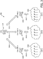
- the management system 100 includes a single CMS 110 in communication with a first OLN 130A via communication link 101A, a second OLN 130B via communication link 101B, and a third OLN 130C via communication link 101C.
- the management system 100 also includes a first VMS 150A in communication with the first OLN 130A via communication link 101D, a second VMS 150B in communication with the second OLN 130B via communication link 101E, and a third VMS 150C in communication with the third OLN 130C via communication link 101F.
- Each of the OLNs 130A-C is topologically interposed between the CMS 110 and a respective of the VMSs 150A-C.
- Communication links 101A-F may include, for example, one or more wireless, wire/cable, and/or fiber optic links.
- the CMS 110 and each of the VMSs 150A-C may include a computer such as a desktop computer, a handheld computer device, a server, and/or a bank of servers. The computer may execute computer program instructions that implement one or more of the functions specified in this application that are associated with such device.
- the CMS 110 may include at least one user interface allowing the customer to perform functions related to the CMS 110 and each of the VMSs 150A-C may include a separate at least one user interface allowing the vendor to perform functions related to its respective VMS 150A-C.
- the CMS 110 may provide different control and/or information capabilities to certain users. For example, in some embodiments a hierarchical control model may be utilized where authorities at different levels access the CMS 110 with different priorities. As an example, different management levels (e.g., local, city, state, national) could have control and/or information capabilities that are tailored for the particular management level.
- Each of the OLNs 130A-C may include one or more direct communication OLN devices such as lighting points, segment/local controllers, and/or other associated assets (e.g., lighting fixtures, sensors, light sources, cameras, storage devices, power sources) that are equipped with control and communication capabilities to enable communication with the CMS 110 and/or with a respective of VMSs 150A-C.
- Each of the OLNs 130A-C may also optionally include one or more managed OLN devices such as lighting points, sensors, lighting fixtures, light sources, cameras, and/or power sources that may be controlled and managed by the CMS 110 and/or a respective of VMSs 150A-C, but cannot establish direct connection with the CMS 110 or a respective VMS 150A-C.
- a managed OLN device may be controlled by the CMS 110 and/or a VMS 150A-C via a direct communication OLN device (e.g., a segment controller) that is in communication with the CMS 110 and/or a VMS 150A-C and that controls the managed OLN device based on input received from the CMS 110 and/or a VMS 150A-C.
- a direct communication OLN device e.g., a segment controller
- the CMS 110 communicates with each of the OLNs 130A-C to remotely control and manage certain aspects of the devices of the OLNs 130A-C, while the VMSs 150A-C connect to their respective OLNs 130A-C and manage other aspects of the devices of the OLNs 130A-C.
- the CMS 110 may communicate with the OLNs 130A-C to control and manage the lighting behavior (e.g., switch on/off, set dimming level, set color level, and/or set lighting schedule) of one or more light sources of the OLNs 130A-C (either directly or via one or more lighting unit, segment controller, etc.).
- the lighting behavior e.g., switch on/off, set dimming level, set color level, and/or set lighting schedule
- the CMS 110 may communicate with the OLNs 130A-C to control and manage measurements and feedback configuration of one or more OLN devices (e.g., receive and manage measurements and/or feedback from one or more OLN devices, alter measurement and feedback status of one or more OLN devices, and/or alter measurement and feedback reporting frequency of one or more OLN devices).
- OLN devices 130A-C may communicate with the CMS 110 to control and manage measurements and feedback configuration of one or more OLN devices (e.g., receive and manage measurements and/or feedback from one or more OLN devices, alter measurement and feedback status of one or more OLN devices, and/or alter measurement and feedback reporting frequency of one or more OLN devices).
- the CMS 110 may also communicate with the OLNs 130A-C to control and manage one or more OLN devices (e.g., manage information of OLN controllers, lighting fixture, sensors, cameras, and/or power sources; switch on/off OLN controllers, lighting fixture, sensors, cameras, and/or power sources; and/or configure controllers, lighting fixture, sensors, cameras, and/or power sources).
- OLN devices e.g., manage information of OLN controllers, lighting fixture, sensors, cameras, and/or power sources; switch on/off OLN controllers, lighting fixture, sensors, cameras, and/or power sources; and/or configure controllers, lighting fixture, sensors, cameras, and/or power sources.
- the VMSs 150A-C may manage other aspects of the OLNs 130A-C.
- the VMSs 150A-C may communicate with respective of the OLNs 130A-C to perform OLN commissioning of one or more devices of the OLNs 130A-C (e.g., assigning geographical information to the device, assigning initial installation location information to the device, assigning initial configuration information to the device, and/or assigning relationships between multiple devices).
- VMSs 150A-C may communicate with respective of the OLNs 130A-C to manage the OLN (e.g., optimize communication between OLN devices, identify and troubleshoot connectivity issues, and/or install software updates).
- the VMSs 150A-C may also communicate with respective of the OLNs 130A-C to provide security management for the OLN (e.g., verify newly connected OLN devices, detect security breaches, and/or correct security issues). Also, for example, the VMSs 150A-C may also communicate with respective of the OLNs 130A-C to control certain vendor specific functionality of one or more of the devices of the OLN.
- This bifurcation of aspects of the control and management of an OLN between the CMS and VMS enables a customer to control and manage certain aspects of multi-vendor OLNs, while leaving many vendor-specific aspects of the control and management of the multi-vendor OLNs up to the VMSs.
- Certain aspects of the control and management of an OLN may also optionally be dictated by either the CMS or the VMS. For example, the CMS may be able to set reporting parameters in certain situations (e.g., at setup and/or in an override situation).
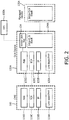
- the CMS 110 is illustrated in communication with a direct communication OLN device 132A of OLN 130A.
- the CMS 110 includes a protocol stack having a link layer / physical layer 111A, a network layer 111B, a transport layer 111C, and an application layer 111D.
- the OLN device 132A includes a protocol stack having a link layer / physical layer 133A, a network layer 133B, a transport layer 133C, and an application layer 133D.
- the application layers 111D and 133D of the CMS 110 and the OLN device 132A utilize a common Application Protocol.
- the Application Protocol may be implemented following the structure and format of existing protocols such as, for example, the HTTP/XML protocol, together with a standard data format (application semantics) for management of OLNs that is well defined and implemented by different OLNs.
- the Application Protocol may not be implemented based on an existing protocol.
- the direct communication OLN device 132A also includes a vendor-specific protocol for communication with VMS 150A and communication with other devices of OLN 130A, such as managed device 135A.
- the vendor-specific protocol will be dependent on the particular vendor utilized for the OLN 130A.
- the vendor-specific protocol may be implemented following the structure and format of existing protocols such as, for example, the HTTP/XML protocol, together with application semantics that are defined by the vendor.
- the illustrated vendor-specific second protocol stack has an intra-OLN component 134A for communication with other devices of OLN 130A and a VMS Application Protocol for communication with the VMS 150A. The translation between the Application Protocol and the vendor-specific protocol is performed at the OLN device 132A.
- This configuration allows both the CMS 110 and the VMS 150A to establish a direct connection with the OLN device 132A, manage the OLN device 132A, and manage other devices associated with the OLN device 132A. Also, this configuration allows the OLN device 132A to establish a direct connection with the CMS 110 and the VMS 150A. In some embodiments the OLN device 132A may communicate with the entire OLN 130A. In other embodiments the OLN device 132A may only communicate with certain segments of the OLN 130A or may not communicate with any other devices of the OLN 130A.
- the common Application Protocol enables communication between the CMS 110 and the OLN device 132A.
- the CMS 110 may communicate with the OLN device 132A and/or other devices of the OLN 130A via the Application Protocol to provide for control of one or more light sources of the OLN 130A, control and management of the measurements and feedback configuration of one or more OLN devices of the OLN 130A, and/or management of one or more OLN devices.
- one or more OLN devices of the OLN 130A may communicate with the CMS 110 to, for example, provide attribute information thereto and/or to provide confirmation of changed configurations in response to a configuration change request.
- OLN 130A may have other devices. Also, it is understood that such other devices may include other direct communication devices that may establish a direct connection with CMS 110 and/or VMS 150A and/or may include other managed devices that may not establish a direct connection with CMS 110 and/or VMS 150A.
- the direct communication OLN devices of OLNs 130B, 130C that communicate with CMS 110 also utilize the common Application Protocol.
- the direct communication OLN devices of OLNs 130B, 130C also include vendor-specific protocols for communication with respective of VMSs 150B, 150C and communication with other devices of OLNs 130B, 130C.
- the vendor-specific protocols will be dependent on the particular vendor utilized for OLNs 130B, 130C.
- the translation between the Application Protocol and the vendor-specific protocol of each of the OLNs 130B, 130C will be performed at one or more direct communication OLN devices of respective of the OLNs 130B, 130C.
- This configuration allows both the CMS 110 and the VMS 150B to establish a connection with and manage the OLN 130B and allows both the CMS 110 and the VMS 150C to establish a connection with and manage the OLN 130C.
- the common Application Protocol enables communication between the CMS 110 and the OLNs 130B, 130C.
- the CMS 110 may communicate with the OLNs 130B, 130C via the Application Protocol to provide for control of one or more light sources of the OLNs 130B, 130C, control and management of the measurements and feedback configuration of one or more OLN devices of the OLNs 130B, 130C, and management of one or more OLN devices of the OLNs 130B, 130C.
- the management system 200 includes a single CMS 210 in communication with a first VMS 250A via communication link 201A, a second VMS 250B via communication link 201B, and a third VMS 250C via communication link 201C.
- the first VMS 250A is in communication with a first OLN 230A via communication link 201D
- the second VMS 250B in communication with a second OLN 230B via communication link 201E
- the third VMS 250C is in communication with a third OLN 230C via communication link 201F.
- Communication links 201A-F may include, for example, one or more wireless, wire/cable, and/or fiber optic links.
- Each of the VMSs 250A-C is topologically interposed between the CMS 210 and a respective of the OLNs 230A-C.
- Each of the OLNs 230A-C may include one or more direct communication OLN devices equipped with control and communication capabilities to enable communication with a respective of the VMSs 250A-C and/or the CMS 210 (via a respective of the VMSs 250A-C).
- Each of the OLNs 230A-C may also optionally include one or more managed OLN devices that may be controlled and managed by the CMS 210 and/or a respective VMS 250A-C, but cannot establish direct connection with a respective of the VMSs 250A-C.
- the CMS 210 communicates with each of the OLNs 230A-C via a respective of the VMSs 250A-C to remotely control and manage certain aspects of the devices of the OLNs 230A-C, while the VMSs 250A-C connect to their respective OLNs 230A-C and manage other aspects of the devices of the OLNs 230A-C and/or the OLNs 230A-C.
- the CMS 210 may communicate with the OLNs 230A-C via VMSs 250A-C to control and manage the lighting behavior of one or more light sources of the OLNs 230A-C; may communicate with the OLNs 230A-C via VMSs 250A-C to control and manage measurements and feedback configuration of one or more OLN devices; and may also communicate with the OLNs 230A-C via VMSs 250A-C to control and manage one or more OLN devices.
- the VMSs 250A-C may communicate with respective of the OLNs 230A-C to perform OLN commissioning of one or more devices of the OLNs 230A-C, to manage the OLNs 230A-C, and to provide security management for the OLNs 230A-C. Also, for example, the VMSs 250A-C may also communicate with respective of the OLNs 230A-C to control certain vendor specific functionality of one or more of the devices of the OLN.
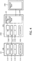
- the CMS 210 is illustrated in communication with the first VMS 250A.
- the CMS 210 includes a protocol stack having a link layer / physical layer 211A, a network layer 211B, a transport layer 211C, and an application layer 211D.
- the first VMS 250A includes a protocol stack having a link layer / physical layer 253A, a network layer 253B, a transport layer 253C, and an application layer 253D.
- the application layers 211D and 253D of the CMS 210 and the device of the OLN 230A utilize a common Application Protocol.
- the Application Protocol may be implemented following the structure and format of existing protocols such as, for example, the HTTP/XML protocol. In other embodiments the Application Protocol may not be implemented based on an existing protocol.
- the first VMS 250A also includes a vendor-specific protocol for communication with one or more devices of the OLN 230A.
- the vendor-specific protocol will be dependent on the particular vendor utilized for OLN 230A.
- the illustrated vendor-specific protocol has an OLN component 234A for communication with one or more devices of OLN 230A.
- the translation between the Application Protocol and the vendor-specific protocol is performed at the first VMS 250A. This configuration allows both the CMS 210 and the VMS 250A to establish a connection with the OLN 230A and manage the OLN 230A.
- the common Application Protocol enables communication between the CMS 210 and the OLN 230A (via VMS 250A) to provide for control of one or more light sources of the OLN 230A, control and management of the measurements and feedback configuration of one or more OLN devices of the OLN 230A, and management of one or more OLN devices. Also, one or more OLN devices of the OLN 230A may communicate with the CMS 210 to, for example, provide attribute information thereto and/or to provide confirmation of changed configurations in response to a configuration change request.
- the second and third VMSs 250B, 250C also utilize the common Application Protocol for communication with the CMS 210 and translate the Application Protocol to a vendor-specific protocol of respective of the OLNs 230B, 230C.
- the vendor-specific protocols will be dependent on the particular vendor(s) utilized for OLNs 230B, 230C.
- This configuration allows both the CMS 210 and the VMS 250B to establish a connection with and manage the OLN 230B and allows both the CMS 210 and the VMS 250C to establish a connection with and manage the OLN 230C.
- the common Application Protocol enables communication between the CMS 210 and the OLNs 230B, 230C.
- the CMS 210 may communicate with the OLNs 230B, 230C via the VMSs 250B, 250C to provide for control of one or more light sources of the OLNs 230B, 230C, control and management of the measurements and feedback configuration of one or more OLN devices of the OLNs 230B, 230C, and management of one or more OLN devices of the OLNs 230B, 230C.
- an embodiment of a method of commissioning and configuring a multi-vendor OLN management system is illustrated.
- One or more aspects of the embodiment of commissioning and configuring an OLN management system may be utilized to commission and/or configure OLN management systems 100 and/or 200.
- devices of an OLN are initialized and confirmed with a VMS.
- installation and commissioning of the OLN devices may be done using vendor-specific equipment and procedures.
- direct communication OLN devices and/or managed devices may execute an initialization procedure to form and/or join the OLN when initially powered up and may confirm their identities with the VMS via communication with the VMS (e.g., via the topology of FIG. 1 or the topology of FIG. 3 ).
- the network forming and/or joining may additionally or alternatively be triggered by a configuration assistant (CA) tool during the installation.
- a CA tool may read information from the devices of the OLN and upload such information to the VMS via a secure communications link.
- OLN devices may automatically initiate the interaction with the VMS to confirm security credentials (e.g., security keys stored in memory of the OLN devices at the factory) and join the OLN.
- information related to the devices of the OLN is provided to the CMS.
- information related to the device of the OLN is uploaded to the CMS via a transportable storage medium.
- a commissioning engineer can upload a file with the OLN device data to the CMS.
- a direct connection is established to the CMS from one or more devices of the OLN or other vendor specific devices (e.g., CA tool or the VMS) to transfer information related to the devices of the OLN.
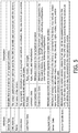
- the information related to the devices of the OLN includes the attributes and capabilities of individual devices of the OLN.
- each of the OLN devices shall implement a common set of attributes that is reported to and understood by the CMS. However, each of the OLN devices may optionally have more attributes than what it reports to the CMS. In some embodiments one or more of the attributes may be adjusted by the vendor. Also, in some embodiments, the vendor may direct which attributes to make available to the CMS. For example, in some embodiments a commissioning engineer may direct OLN devices to only provide certain attributes to the CMS. Also, for example, in some embodiments a VMS may alter which attributes are provided by the OLN to the CMS.
- OLN device attributes that may be provided to a CMS is illustrated, along with a brief description of each of those device attributes.
- the attributes include Device Type, CMS Address, Name, Geolocation, Light Point Data, Segment Data, Sensor Data, and Vendor Specific Data.
- the CMS may confirm the information with the OLN devices. For instance, if the information is provided directly by the OLN device, the CMS may just confirm the reception of the data using the existing connection with the OLN device. If the information is provided by other means (e.g., VMS or CA tool upload), the CMS may try to establish a secure connection with the OLN devices and then confirm the device information.
- the CMS may try to establish a secure connection with the OLN devices and then confirm the device information.
- a unique CMS ID is assigned to each of the OLN devices.
- the CMS ID is utilized to uniquely identify each device and enable addressable network communication between the CMS and the OLN devices.
- a VMS associated with the OLN may also utilize the CMS ID or may alternatively utilize a different ID for addressable network communication between the VMS and the OLN devices.
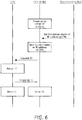
- FIG. 6 an embodiment of a method of OLN device ID assignment is illustrated.
- a commissioning tool provides the domain name or IP address of the CMS to the OLN devices.
- each OLN device Utilizing the domain name or IP address of the CMS, each OLN device sends an ID request to the CMS.
- the CMS assigns a CMS ID, stores the CMS ID, and sends a response to the OLN device confirming assignment of the CMS ID.
- the response may include the CMS ID and the OLN device may store the CMS ID.
- the CMS may assign a block of unique CMS IDs to the vendors and the vendors may assign those CMS IDs to the OLN devices during the vendor initialization of the OLN.
- the CMS may communicate a block of unique CMS IDs to a VMS and the VMS may assign those CMS IDs to the OLN devices during the vendor initialization of the OLN.
- the CMS may communicate a block of unique CMS IDs to a vendor and a commissioning engineer may utilize a CA or other apparatus to assign those CMS IDs to the OLN devices during the vendor initialization of the OLN.
- Managed devices of the OLN which rely on direct connection with direct communication OLN devices to establish the connection with the CMS may also acquire a CMS ID.
- CMS ID may also be assigned to the managed devices by the VMS or other vendor's tools during the OLN initialization.
- the managed devices of the OLN may also request the CMS ID by contacting a direct communication OLN device, which will forward the managed device's ID request to the CMS, and relay the response (optionally with assigned CMS ID) to the managed device.
- the managed device may also relay the assigned CMS ID to a commissioning tool and/or to the VMS.
- the OLN devices are configured from the CMS.
- the CMS can configure the operation of certain aspects of the OLN devices via communication of device configuration messages to the OLN (either directly as illustrated in FIG. 1 or via an associated VMS as illustrated in FIG. 3 ).
- one or more configuration messages may be transmitted to the OLN devices and contain new values for the attributes of the OLN devices.
- lighting configuration messages may be directed to a segment controller controlling a plurality of lighting fixtures and contain values to adjust the on/off schedule of those lighting fixtures.
- lighting configuration messages may be directed at a lighting unit and adjust minimum and/or maximum dimming values of the lighting unit.
- OLN devices across networks from multiple vendors should be able to read and recognize the attributes in the configuration messages.
- the OLN device to which it was directed may notify the CMS with an error message, which may also optionally indicate which attribute(s) is not valid.
- Some attributes of OLN devices may be vendor specific, and as such, the CMS may not have the capability to set such attributes, unless a special feature is enabled by the vendor.
- the CMS may also send configuration attributes updates (e . g ., via new SET_CONFIG messages) to one or more OLN devices at any time.
- Configuration changes may be generated in response to, inter alia , a change in the capabilities of the OLN devices, a user request, and/or a specific event that has been detected.
- the CMS can receive the change information (e . g ., a user may manually input change or the lighting unit reports the change) and start operating the lighting unit in accord with its new capabilities.
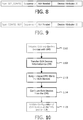
- OLN devices may also send a configuration change report message (e . g ., CONIFG_REP messages having the general format illustrated in FIG. 9 ) to the CMS.
- the CMS may confirm/acknowledge the new attribute values/capabilities with the OLN devices.
- an OLN device may inform the CMS of a vendor upgrade to the devices' software version, and the CMS may acknowledge the new value.
- an OLN device may confirm change of its configuration in response to a CMS configuration message via a configuration change report message.
- certain configuration changes requested by the CMS to the OLN devices are optionally validated at the VMS and/or the OLN.
- Certain attributes may impact the overall OLN performance, and as such, their changes may be coordinated with the VMS. For example, the frequency of measurement reports that would be generated by the OLN devices in response to a request by the CMS may overload the OLN and cause serious availability problems with the OLN.
- users may be allowed to configure such parameters from the CMS, in some embodiments the implementation of the requested configuration must be confirmed by the VMS and/or the OLN. This may be done by connecting to the VMS once a new request for change is received and/or by hosting local OLN implementation policies that are set by the VMS, and checking all requested configuration changes against such policies.
- the maximum frequency of periodic power metering or other measurement reports from devices to the CMS may be controlled by the VMS in order to avoid overload of the OLN.
- requests by the CMS to increase the measurement reporting frequency of OLN devices above a certain threshold could be denied by the OLN.
- the VMS and/or OLN may override certain configuration change requests by the CMS ( e . g ., by substituting alternative configuration values determined at the VMS and/or OLN) and/or may deny such requested changes (optionally suggesting other acceptable alternatives).
- the configuration change report messages may optionally be used to confirm an overridden attribute configuration and/or to suggest a change to a previous attribute configuration request from the CMS.
- inventive embodiments are presented by way of example only and that, within the scope of the appended claims and equivalents thereto, inventive embodiments may be practiced otherwise than as specifically described and claimed.
- inventive embodiments of the present disclosure are directed to each individual feature, system, article, material, kit, and/or method described herein.
- a reference to "A and/or B", when used in conjunction with open-ended language such as “comprising” can refer, in one embodiment, to A only (optionally including elements other than B); in another embodiment, to B only (optionally including elements other than A); in yet another embodiment, to both A and B (optionally including other elements); etc.
- the phrase "at least one,” in reference to a list of one or more elements, should be understood to mean at least one element selected from any one or more of the elements in the list of elements, but not necessarily including at least one of each and every element specifically listed within the list of elements and not excluding any combinations of elements in the list of elements.
- This definition also allows that elements may optionally be present other than the elements specifically identified within the list of elements to which the phrase "at least one" refers, whether related or unrelated to those elements specifically identified.
- At least one of A and B can refer, in one embodiment, to at least one, optionally including more than one, A, with no B present (and optionally including elements other than B); in another embodiment, to at least one, optionally including more than one, B, with no A present (and optionally including elements other than A); in yet another embodiment, to at least one, optionally including more than one, A, and at least one, optionally including more than one, B (and optionally including other elements); etc.
Claims (20)
- Système de gestion de réseaux d'éclairage extérieur comprenant :au moins un premier et un second réseaux d'éclairage extérieur (130A-C, 230A-C) incluant chacun une pluralité de dispositifs de réseau d'éclairage extérieur (132A, 135A), chacun desdits premier et second réseaux d'éclairage extérieur utilisant un premier ou un second protocole respectif pour communiquer avec leur pluralité respective de dispositifs de réseau d'éclairage extérieur (132A, 135A),un système de gestion centrale (110, 210) en communication avec chacun desdits réseaux d'éclairage extérieur (130A-C, 230A-C), ledit système de gestion centrale (110, 210) envoyant des instructions de configuration de réseau d'éclairage extérieur à chacun desdits réseaux d'éclairage extérieur (130A-C, 230A-C) utilisant un protocole de réseau commun et recevant des informations de dispositifs de réseau d'éclairage extérieur de chacun desdits réseaux d'éclairage extérieur (130A-C, 230A-C) utilisant le protocole de réseau commun, lesdites informations de dispositifs de réseau d'éclairage extérieur incluant des détails desdits dispositifs de réseau d'éclairage ;
caractérisé en ce que lesdits premier et second protocoles sont distincts et différents ; etdans lequel lesdites instructions de configuration de réseau d'éclairage extérieur provenant dudit système de gestion centrale (110, 210), en utilisant le protocole commun, sont traduites par lesdits premier et second réseaux d'éclairage extérieur (130A-C, 230A-C) en ledit premier ou ledit second protocole et utilisées pour établir une configuration d'au moins l'un desdits dispositifs de réseau d'éclairage extérieur (132A, 135A) ;un premier système de gestion de fournisseur (150A-C, 250A-C) en communication avec le premier réseau d'éclairage extérieur (130A-C, 230A-C) pour communiquer des instructions de gestion de fournisseur audit premier réseau d'éclairage extérieur. - Système selon la revendication 1, comprenant en outre un second système de gestion de fournisseur (150A-C, 250A-C) en communication avec le second réseau d'éclairage extérieur (130A-C, 230A-C).
- Système selon la revendication 1, dans lequel au moins un groupe desdites instructions de configuration envoyées audit premier réseau d'éclairage extérieur est également envoyé audit premier système de gestion de fournisseur (150A-C, 250A-C) et vérifié par ledit premier système de gestion de fournisseur (150A-C, 250A-C).
- Système selon la revendication 1, dans lequel lesdites instructions de configuration d'éclairage incluent au moins une configuration parmi une configuration de gradation, une configuration de planification, une configuration de mesures et une configuration de commande de couleur.
- Système selon la revendication 1, dans lequel au moins un groupe desdites instructions de configuration envoyées audit premier réseau d'éclairage extérieur est également envoyé audit premier système de gestion de fournisseur (150A-C, 250A-C) et vérifié par ledit premier système de gestion de fournisseur (150A-C, 250A-C) avant de modifier ladite configuration d'au moins l'un desdits dispositifs de réseau d'éclairage extérieur dudit premier réseau d'éclairage extérieur.
- Système selon la revendication 1, dans lequel ledit système de gestion centrale (110, 210) est en communication avec chacun desdits réseaux d'éclairage extérieur (130A-C, 230A-C) via une pile de protocoles de système de gestion centrale ayant une première couche d'application.
- Système selon la revendication 5, dans lequel ledit premier système de gestion de fournisseur (150A-C, 250A-C) est en communication avec ledit premier réseau d'éclairage extérieur par l'intermédiaire d'une première pile de protocoles de fournisseur ayant une deuxième couche d'application distincte de ladite première couche d'application.
- Système selon la revendication 6, comprenant en outre un second système de gestion de fournisseur (150A-C, 250A-C) en communication avec ledit second réseau d'éclairage extérieur desdits réseaux d'éclairage extérieur (130A-C, 230A-C), dans lequel ledit second système de gestion de fournisseur (150A-C, 250A-C) est en communication avec ledit second réseau d'éclairage extérieur via une seconde pile de protocoles de fournisseur ayant une troisième couche d'application distincte de ladite première couche d'application et distincte de ladite deuxième couche d'application.
- Système selon la revendication 1, dans lequel ledit premier réseau d'éclairage extérieur est interposé topologiquement entre ledit système de gestion centrale (110, 210) et ledit premier système de gestion de fournisseur (150A-C, 250A-C).
- Système selon la revendication 1, dans lequel ledit premier système de gestion de fournisseur (150A-C, 250A-C) est interposé topologiquement entre ledit système de gestion centrale (110, 210) et ledit premier réseau d'éclairage extérieur.
- Procédé de gestion d'une pluralité de réseaux d'éclairage extérieur, dans lequel un premier réseau d'éclairage extérieur et un second réseau d'éclairage extérieur utilisent un protocole de communication distinct et différent, comprenant :recevoir des premières instructions de configuration du système de gestion centrale depuis un système de gestion centrale ;traduire lesdites premières instructions de configuration de gestion centrale en instructions de configuration de premier réseau d'éclairage extérieur distinctes et différentes lisibles par des premiers dispositifs dudit premier réseau d'éclairage extérieur ;recevoir des secondes instructions de configuration du système de gestion centrale depuis ledit système de gestion centrale ;traduire lesdites secondes instructions de configuration de gestion centrale en des instructions de configuration de second réseau d'éclairage extérieur distinctes et différentes lisibles par des seconds dispositifs dudit second réseau d'éclairage extérieur ;recevoir des première instructions de gestion de fournisseur depuis un premier système de gestion de fournisseur lisibles par lesdits premiers dispositifs ; etrecevoir des secondes instructions de gestion de fournisseur depuis un second système de gestion de fournisseur lisibles par lesdits seconds dispositifs.
- Procédé selon la revendication 11, comprenant en outre la réception de données d'informations de dispositifs desdits premiers dispositifs, la traduction desdites données d'informations de dispositifs en données de système de gestion centrale distinctes et différentes lisibles par ledit système de gestion centrale, et l'envoi desdites données de système de gestion centrale audit système de gestion centrale.
- Procédé selon la revendication 11, comprenant en outre la validation desdites premières instructions de configuration de gestion centrale.
- Appareil de gestion de réseau d'éclairage extérieur, comprenant :au moins une connexion de système de gestion centrale, ladite connexion de système de gestion centrale recevant des instructions de configuration de gestion centrale, utilisant un protocole de réseau commun, en provenance d'un système de gestion centrale (110, 210) ;au moins un dispositif de commande opérationnel pour traduire lesdites instructions de configuration de gestion centrale en instructions de configuration de réseau d'éclairage extérieur dirigées par gestion centrale selon un premier ou un second protocole ;au moins une connexion de réseau d'éclairage extérieur envoyant lesdites instructions de configuration de réseau d'éclairage extérieur dirigées par gestion centrale à au moins un dispositif de réseau d'éclairage extérieur (132A, 135A) d'un premier et d'un second réseaux d'éclairage extérieur (130A-C, 230A-C), chacun incluant une pluralité de dispositifs de réseau d'éclairage extérieur (132A, 135A), dans lesquels chacun desdits premier et second réseaux d'éclairage extérieur utilise respectivement lesdits premier et second protocoles pour communiquer avec leur pluralité respective de dispositifs de réseau d'éclairage extérieur (132A, 135A), caractérisé en ce que les premier et second protocoles sont distincts et différents ; etune entrée de système de gestion de fournisseur, ladite entrée de système de gestion de fournisseur recevant des instructions de gestion de fournisseur provenant d'un système de gestion de fournisseur (150A-C, 250A-C), pour communiquer des instructions de gestion de fournisseur audit premier réseau d'éclairage extérieur.
- Appareil selon la revendication 14, dans lequel au moins certaines desdites instructions de gestion de fournisseur indiquent si au moins certaines desdites instructions de configuration de réseau d'éclairage extérieur dirigées par gestion centrale sont envoyées audit au moins un dispositif de réseau d'éclairage extérieur (132A, 135A).
- Appareil selon la revendication 14, dans lequel ladite connexion de système de gestion centrale transmet des informations de dispositifs de réseau d'éclairage extérieur audit système de gestion centrale (110, 210), lesdites informations de dispositif de réseau d'éclairage extérieur incluant des attributs dudit au moins un dispositif de réseau d'éclairage extérieur (132A, 135A).
- Appareil selon la revendication 16, dans lequel ladite connexion de système de gestion centrale transmet une confirmation de changement de configuration de réseau d'éclairage extérieur audit système de gestion centrale (110, 210), ladite confirmation de changement de configuration de réseau d'éclairage extérieur étant envoyée en réponse au fait que ledit au moins un dispositif de réseau d'éclairage extérieur (132A, 135A) modifie une configuration sur la base desdites instructions de configuration de réseau d'éclairage extérieur dirigées par gestion centrale.
- Appareil selon la revendication 14, dans lequel lesdites instructions de gestion de fournisseur incluent au moins l'une parmi des instructions d'appairage de réseaux d'éclairage extérieur, des instructions de gestion de réseaux d'éclairage extérieur, des instructions de dépannage de réseau d'éclairage extérieur, et des instructions de gestion de sécurité de réseau d'éclairage extérieur.
- Appareil selon la revendication 14, dans lequel ladite connexion de système de gestion centrale, ladite connexion de réseau d'éclairage extérieur, et ladite entrée de système de gestion de fournisseur se trouvent toutes au niveau d'un dispositif de réseau d'éclairage à communication directe (132A).
- Appareil selon la revendication 14, dans lequel ladite connexion de système de gestion centrale, ladite connexion de réseau d'éclairage extérieur, et ladite entrée de gestion de fournisseur se trouvent toutes au niveau dudit système de gestion de fournisseur (150A-C, 250A-C).
Priority Applications (2)
| Application Number | Priority Date | Filing Date | Title |
|---|---|---|---|
| EP19155278.5A EP3512309B1 (fr) | 2012-01-20 | 2013-01-11 | Procédés et appareil pour la gestion de réseaux d'éclairage extérieur |
| PL13706728T PL2805584T5 (pl) | 2012-01-20 | 2013-01-11 | Sposoby i urządzenia do zarządzania sieciami oświetlenia zewnętrznego |
Applications Claiming Priority (2)
| Application Number | Priority Date | Filing Date | Title |
|---|---|---|---|
| US201261588994P | 2012-01-20 | 2012-01-20 | |
| PCT/IB2013/050258 WO2013108162A1 (fr) | 2012-01-20 | 2013-01-11 | Procédés et appareils pour la gestion de réseaux d'éclairage extérieur |
Related Child Applications (2)
| Application Number | Title | Priority Date | Filing Date |
|---|---|---|---|
| EP19155278.5A Division EP3512309B1 (fr) | 2012-01-20 | 2013-01-11 | Procédés et appareil pour la gestion de réseaux d'éclairage extérieur |
| EP19155278.5A Division-Into EP3512309B1 (fr) | 2012-01-20 | 2013-01-11 | Procédés et appareil pour la gestion de réseaux d'éclairage extérieur |
Publications (3)
| Publication Number | Publication Date |
|---|---|
| EP2805584A1 EP2805584A1 (fr) | 2014-11-26 |
| EP2805584B1 true EP2805584B1 (fr) | 2019-04-03 |
| EP2805584B2 EP2805584B2 (fr) | 2022-01-19 |
Family
ID=47754897
Family Applications (2)
| Application Number | Title | Priority Date | Filing Date |
|---|---|---|---|
| EP19155278.5A Active EP3512309B1 (fr) | 2012-01-20 | 2013-01-11 | Procédés et appareil pour la gestion de réseaux d'éclairage extérieur |
| EP13706728.6A Active EP2805584B2 (fr) | 2012-01-20 | 2013-01-11 | Methode et appareil pour la gestion d'un réseau d'éclairage d'extérieur |
Family Applications Before (1)
| Application Number | Title | Priority Date | Filing Date |
|---|---|---|---|
| EP19155278.5A Active EP3512309B1 (fr) | 2012-01-20 | 2013-01-11 | Procédés et appareil pour la gestion de réseaux d'éclairage extérieur |
Country Status (8)
| Country | Link |
|---|---|
| US (1) | US9468076B2 (fr) |
| EP (2) | EP3512309B1 (fr) |
| JP (1) | JP6214560B2 (fr) |
| CN (1) | CN104054401B (fr) |
| BR (1) | BR112014017456A8 (fr) |
| ES (1) | ES2731326T5 (fr) |
| PL (1) | PL2805584T5 (fr) |
| WO (1) | WO2013108162A1 (fr) |
Families Citing this family (6)
| Publication number | Priority date | Publication date | Assignee | Title |
|---|---|---|---|---|
| US9161419B2 (en) * | 2012-07-02 | 2015-10-13 | International Business Machines Corporation | Intelligent and coordinated lighting of a lighting device |
| US10098209B2 (en) | 2014-10-17 | 2018-10-09 | Philips Lighting Holding B.V. | System and method for outdoor lighting operation and management using its protocols and connectivity infrastructure |
| EP3278634B1 (fr) * | 2015-04-02 | 2021-05-12 | Signify Holding B.V. | Système de dispositif connecté |
| CN107135567B (zh) * | 2016-02-29 | 2020-05-05 | 哈纳姆阿泰克株式会社 | 发光控制系统 |
| JP2019220269A (ja) * | 2018-06-15 | 2019-12-26 | アイリスオーヤマ株式会社 | 照明システム |
| DE102020100399A1 (de) * | 2020-01-10 | 2021-07-15 | Zumtobel Lighting Gmbh | Leuchte mit integriertem Selbsttest |
Citations (2)
| Publication number | Priority date | Publication date | Assignee | Title |
|---|---|---|---|---|
| WO2007033053A2 (fr) | 2005-09-12 | 2007-03-22 | Acuity Brands, Inc. | Systeme de gestion de luminaires, presentant des gestionnaires intelligents en reseau, et ses applications |
| WO2008070981A1 (fr) | 2006-12-12 | 2008-06-19 | Tir Technology Lp | Système et procédé permettant de commander un éclairage |
Family Cites Families (11)
| Publication number | Priority date | Publication date | Assignee | Title |
|---|---|---|---|---|
| US8433426B2 (en) * | 2005-06-30 | 2013-04-30 | Led Roadway Lighting Ltd | Adaptive energy performance monitoring and control system |
| CN101617565B (zh) * | 2006-11-10 | 2011-11-02 | 飞利浦固体状态照明技术公司 | 用于控制串联的led的方法和装置 |
| US8588830B2 (en) * | 2007-02-02 | 2013-11-19 | Inovus Solar, Inc | Wireless autonomous solar-powered outdoor lighting and energy and information management network |
| WO2009033051A1 (fr) | 2007-09-07 | 2009-03-12 | Philips Solid-State Lighting Solutions | Procédés et appareil destinés à fournir un éclairage par projecteur à base de del dans des applications d'éclairage d'étage |
| TW201220952A (en) * | 2010-03-29 | 2012-05-16 | Koninkl Philips Electronics Nv | Network of heterogeneous devices including at least one outdoor lighting fixture node |
| WO2012090142A2 (fr) | 2010-12-28 | 2012-07-05 | Koninklijke Philips Electronics N.V. | Système de commande de réseau d'éclairage d'extérieur |
| US20130249409A1 (en) * | 2011-05-12 | 2013-09-26 | LSI Saco Technologies, Inc. | Lighting System Control and Synthetic Event Generation |
| KR101100228B1 (ko) * | 2011-05-25 | 2011-12-28 | 엘지전자 주식회사 | 조명 시스템 및 조명 시스템에서의 주소 설정, 관리 및 제어 방법 |
| CN202085372U (zh) | 2011-06-16 | 2011-12-21 | 山东浪潮华光照明有限公司 | 一种基于物联网的led路灯智能管理系统 |
| US9161419B2 (en) * | 2012-07-02 | 2015-10-13 | International Business Machines Corporation | Intelligent and coordinated lighting of a lighting device |
| CN104620680B (zh) * | 2012-07-10 | 2018-10-16 | 飞利浦灯具控股公司 | 用于提供室外照明系统的自适应测量和协调维护的系统和方法 |
-
2013
- 2013-01-11 EP EP19155278.5A patent/EP3512309B1/fr active Active
- 2013-01-11 EP EP13706728.6A patent/EP2805584B2/fr active Active
- 2013-01-11 ES ES13706728T patent/ES2731326T5/es active Active
- 2013-01-11 US US14/372,376 patent/US9468076B2/en active Active
- 2013-01-11 CN CN201380006021.8A patent/CN104054401B/zh active Active
- 2013-01-11 BR BR112014017456A patent/BR112014017456A8/pt not_active Application Discontinuation
- 2013-01-11 PL PL13706728T patent/PL2805584T5/pl unknown
- 2013-01-11 JP JP2014552723A patent/JP6214560B2/ja active Active
- 2013-01-11 WO PCT/IB2013/050258 patent/WO2013108162A1/fr active Application Filing
Patent Citations (2)
| Publication number | Priority date | Publication date | Assignee | Title |
|---|---|---|---|---|
| WO2007033053A2 (fr) | 2005-09-12 | 2007-03-22 | Acuity Brands, Inc. | Systeme de gestion de luminaires, presentant des gestionnaires intelligents en reseau, et ses applications |
| WO2008070981A1 (fr) | 2006-12-12 | 2008-06-19 | Tir Technology Lp | Système et procédé permettant de commander un éclairage |
Also Published As
| Publication number | Publication date |
|---|---|
| EP3512309A1 (fr) | 2019-07-17 |
| EP3512309B1 (fr) | 2024-03-13 |
| EP2805584B2 (fr) | 2022-01-19 |
| CN104054401B (zh) | 2017-06-09 |
| US20140354177A1 (en) | 2014-12-04 |
| CN104054401A (zh) | 2014-09-17 |
| PL2805584T5 (pl) | 2022-06-27 |
| PL2805584T3 (pl) | 2019-09-30 |
| JP6214560B2 (ja) | 2017-10-18 |
| ES2731326T5 (es) | 2022-04-25 |
| BR112014017456A8 (pt) | 2017-07-04 |
| BR112014017456A2 (pt) | 2017-06-13 |
| EP2805584A1 (fr) | 2014-11-26 |
| JP2015513757A (ja) | 2015-05-14 |
| WO2013108162A1 (fr) | 2013-07-25 |
| ES2731326T3 (es) | 2019-11-15 |
| US9468076B2 (en) | 2016-10-11 |
Similar Documents
| Publication | Publication Date | Title |
|---|---|---|
| US11398924B2 (en) | Wireless lighting controller for a lighting control system | |
| US9974150B2 (en) | Secure device rejoining for mesh network devices | |
| EP2805584B1 (fr) | Methode et appareil pour la gestion d'un réseau d'éclairage d'extérieur | |
| US10743390B2 (en) | Out-of-the-box commissioning of a control system | |
| US9826601B2 (en) | Systems and methods for lighting control | |
| US11221599B2 (en) | Systems and methods for managing environmental conditions | |
| CN106717127B (zh) | 用于照明系统的控制设备和用于配置和启动所述控制设备的方法 | |
| US20150084547A1 (en) | DALI commissioning tools and methods for implementing | |
| JP2015513757A5 (fr) | ||
| CA2949128A1 (fr) | Mecanismes de commande d'eclairage sans fil et methodes | |
| CN111742610A (zh) | 利用受控加入模式的调试方法和装置 | |
| Mathews et al. | Transition from closed system to Internet of Things: A study in standardizing building lighting systems | |
| Matthews et al. | Transition from closed system to Internet of Things |
Legal Events
| Date | Code | Title | Description |
|---|---|---|---|
| PUAI | Public reference made under article 153(3) epc to a published international application that has entered the european phase |
Free format text: ORIGINAL CODE: 0009012 |
|
| 17P | Request for examination filed |
Effective date: 20140820 |
|
| AK | Designated contracting states |
Kind code of ref document: A1 Designated state(s): AL AT BE BG CH CY CZ DE DK EE ES FI FR GB GR HR HU IE IS IT LI LT LU LV MC MK MT NL NO PL PT RO RS SE SI SK SM TR |
|
| DAX | Request for extension of the european patent (deleted) | ||
| RAP1 | Party data changed (applicant data changed or rights of an application transferred) |
Owner name: PHILIPS LIGHTING HOLDING B.V. |
|
| RIN1 | Information on inventor provided before grant (corrected) |
Inventor name: JIANG, DAN Inventor name: CAVALCANTI, DAVE ALBERTO TAVARES Inventor name: YANG, YONG |
|
| STAA | Information on the status of an ep patent application or granted ep patent |
Free format text: STATUS: EXAMINATION IS IN PROGRESS |
|
| 17Q | First examination report despatched |
Effective date: 20171114 |
|
| GRAP | Despatch of communication of intention to grant a patent |
Free format text: ORIGINAL CODE: EPIDOSNIGR1 |
|
| STAA | Information on the status of an ep patent application or granted ep patent |
Free format text: STATUS: GRANT OF PATENT IS INTENDED |
|
| INTG | Intention to grant announced |
Effective date: 20181026 |
|
| RAP1 | Party data changed (applicant data changed or rights of an application transferred) |
Owner name: PHILIPS LIGHTING HOLDING B.V. |
|
| GRAS | Grant fee paid |
Free format text: ORIGINAL CODE: EPIDOSNIGR3 |
|
| GRAA | (expected) grant |
Free format text: ORIGINAL CODE: 0009210 |
|
| STAA | Information on the status of an ep patent application or granted ep patent |
Free format text: STATUS: THE PATENT HAS BEEN GRANTED |
|
| RAP1 | Party data changed (applicant data changed or rights of an application transferred) |
Owner name: SIGNIFY HOLDING B.V. |
|
| AK | Designated contracting states |
Kind code of ref document: B1 Designated state(s): AL AT BE BG CH CY CZ DE DK EE ES FI FR GB GR HR HU IE IS IT LI LT LU LV MC MK MT NL NO PL PT RO RS SE SI SK SM TR |
|
| REG | Reference to a national code |
Ref country code: GB Ref legal event code: FG4D |
|
| REG | Reference to a national code |
Ref country code: CH Ref legal event code: EP Ref country code: AT Ref legal event code: REF Ref document number: 1117377 Country of ref document: AT Kind code of ref document: T Effective date: 20190415 |
|
| REG | Reference to a national code |
Ref country code: DE Ref legal event code: R096 Ref document number: 602013053250 Country of ref document: DE |
|
| REG | Reference to a national code |
Ref country code: IE Ref legal event code: FG4D |
|
| REG | Reference to a national code |
Ref country code: CH Ref legal event code: NV Representative=s name: FELBER UND PARTNER AG, CH |
|
| REG | Reference to a national code |
Ref country code: NL Ref legal event code: FP |
|
| REG | Reference to a national code |
Ref country code: SE Ref legal event code: TRGR |
|
| REG | Reference to a national code |
Ref country code: LT Ref legal event code: MG4D |
|
| REG | Reference to a national code |
Ref country code: NO Ref legal event code: T2 Effective date: 20190403 |
|
| REG | Reference to a national code |
Ref country code: AT Ref legal event code: MK05 Ref document number: 1117377 Country of ref document: AT Kind code of ref document: T Effective date: 20190403 |
|
| PG25 | Lapsed in a contracting state [announced via postgrant information from national office to epo] |
Ref country code: PT Free format text: LAPSE BECAUSE OF FAILURE TO SUBMIT A TRANSLATION OF THE DESCRIPTION OR TO PAY THE FEE WITHIN THE PRESCRIBED TIME-LIMIT Effective date: 20190803 Ref country code: HR Free format text: LAPSE BECAUSE OF FAILURE TO SUBMIT A TRANSLATION OF THE DESCRIPTION OR TO PAY THE FEE WITHIN THE PRESCRIBED TIME-LIMIT Effective date: 20190403 Ref country code: AL Free format text: LAPSE BECAUSE OF FAILURE TO SUBMIT A TRANSLATION OF THE DESCRIPTION OR TO PAY THE FEE WITHIN THE PRESCRIBED TIME-LIMIT Effective date: 20190403 Ref country code: CZ Free format text: LAPSE BECAUSE OF FAILURE TO SUBMIT A TRANSLATION OF THE DESCRIPTION OR TO PAY THE FEE WITHIN THE PRESCRIBED TIME-LIMIT Effective date: 20190403 Ref country code: LT Free format text: LAPSE BECAUSE OF FAILURE TO SUBMIT A TRANSLATION OF THE DESCRIPTION OR TO PAY THE FEE WITHIN THE PRESCRIBED TIME-LIMIT Effective date: 20190403 |
|
| PG25 | Lapsed in a contracting state [announced via postgrant information from national office to epo] |
Ref country code: GR Free format text: LAPSE BECAUSE OF FAILURE TO SUBMIT A TRANSLATION OF THE DESCRIPTION OR TO PAY THE FEE WITHIN THE PRESCRIBED TIME-LIMIT Effective date: 20190704 Ref country code: RS Free format text: LAPSE BECAUSE OF FAILURE TO SUBMIT A TRANSLATION OF THE DESCRIPTION OR TO PAY THE FEE WITHIN THE PRESCRIBED TIME-LIMIT Effective date: 20190403 Ref country code: BG Free format text: LAPSE BECAUSE OF FAILURE TO SUBMIT A TRANSLATION OF THE DESCRIPTION OR TO PAY THE FEE WITHIN THE PRESCRIBED TIME-LIMIT Effective date: 20190703 Ref country code: LV Free format text: LAPSE BECAUSE OF FAILURE TO SUBMIT A TRANSLATION OF THE DESCRIPTION OR TO PAY THE FEE WITHIN THE PRESCRIBED TIME-LIMIT Effective date: 20190403 |
|
| PG25 | Lapsed in a contracting state [announced via postgrant information from national office to epo] |
Ref country code: AT Free format text: LAPSE BECAUSE OF FAILURE TO SUBMIT A TRANSLATION OF THE DESCRIPTION OR TO PAY THE FEE WITHIN THE PRESCRIBED TIME-LIMIT Effective date: 20190403 Ref country code: IS Free format text: LAPSE BECAUSE OF FAILURE TO SUBMIT A TRANSLATION OF THE DESCRIPTION OR TO PAY THE FEE WITHIN THE PRESCRIBED TIME-LIMIT Effective date: 20190803 |
|
| REG | Reference to a national code |
Ref country code: DE Ref legal event code: R026 Ref document number: 602013053250 Country of ref document: DE |
|
| PLBI | Opposition filed |
Free format text: ORIGINAL CODE: 0009260 |
|
| PLAX | Notice of opposition and request to file observation + time limit sent |
Free format text: ORIGINAL CODE: EPIDOSNOBS2 |
|
| PG25 | Lapsed in a contracting state [announced via postgrant information from national office to epo] |
Ref country code: DK Free format text: LAPSE BECAUSE OF FAILURE TO SUBMIT A TRANSLATION OF THE DESCRIPTION OR TO PAY THE FEE WITHIN THE PRESCRIBED TIME-LIMIT Effective date: 20190403 Ref country code: EE Free format text: LAPSE BECAUSE OF FAILURE TO SUBMIT A TRANSLATION OF THE DESCRIPTION OR TO PAY THE FEE WITHIN THE PRESCRIBED TIME-LIMIT Effective date: 20190403 Ref country code: RO Free format text: LAPSE BECAUSE OF FAILURE TO SUBMIT A TRANSLATION OF THE DESCRIPTION OR TO PAY THE FEE WITHIN THE PRESCRIBED TIME-LIMIT Effective date: 20190403 Ref country code: SK Free format text: LAPSE BECAUSE OF FAILURE TO SUBMIT A TRANSLATION OF THE DESCRIPTION OR TO PAY THE FEE WITHIN THE PRESCRIBED TIME-LIMIT Effective date: 20190403 |
|
| 26 | Opposition filed |
Opponent name: MOLNIA, DAVID Effective date: 20200103 |
|
| REG | Reference to a national code |
Ref country code: FI Ref legal event code: MDE Opponent name: MOLNIA, DAVID |
|
| PG25 | Lapsed in a contracting state [announced via postgrant information from national office to epo] |
Ref country code: SM Free format text: LAPSE BECAUSE OF FAILURE TO SUBMIT A TRANSLATION OF THE DESCRIPTION OR TO PAY THE FEE WITHIN THE PRESCRIBED TIME-LIMIT Effective date: 20190403 |
|
| PG25 | Lapsed in a contracting state [announced via postgrant information from national office to epo] |
Ref country code: TR Free format text: LAPSE BECAUSE OF FAILURE TO SUBMIT A TRANSLATION OF THE DESCRIPTION OR TO PAY THE FEE WITHIN THE PRESCRIBED TIME-LIMIT Effective date: 20190403 |
|
| PG25 | Lapsed in a contracting state [announced via postgrant information from national office to epo] |
Ref country code: SI Free format text: LAPSE BECAUSE OF FAILURE TO SUBMIT A TRANSLATION OF THE DESCRIPTION OR TO PAY THE FEE WITHIN THE PRESCRIBED TIME-LIMIT Effective date: 20190403 |
|
| PLBB | Reply of patent proprietor to notice(s) of opposition received |
Free format text: ORIGINAL CODE: EPIDOSNOBS3 |
|
| PG25 | Lapsed in a contracting state [announced via postgrant information from national office to epo] |
Ref country code: MC Free format text: LAPSE BECAUSE OF FAILURE TO SUBMIT A TRANSLATION OF THE DESCRIPTION OR TO PAY THE FEE WITHIN THE PRESCRIBED TIME-LIMIT Effective date: 20190403 |
|
| REG | Reference to a national code |
Ref country code: BE Ref legal event code: MM Effective date: 20200131 |
|
| PG25 | Lapsed in a contracting state [announced via postgrant information from national office to epo] |
Ref country code: LU Free format text: LAPSE BECAUSE OF NON-PAYMENT OF DUE FEES Effective date: 20200111 |
|
| PG25 | Lapsed in a contracting state [announced via postgrant information from national office to epo] |
Ref country code: BE Free format text: LAPSE BECAUSE OF NON-PAYMENT OF DUE FEES Effective date: 20200131 |
|
| PG25 | Lapsed in a contracting state [announced via postgrant information from national office to epo] |
Ref country code: IE Free format text: LAPSE BECAUSE OF NON-PAYMENT OF DUE FEES Effective date: 20200111 |
|
| REG | Reference to a national code |
Ref country code: CH Ref legal event code: PK Free format text: BERICHTIGUNGEN |
|
| RIC2 | Information provided on ipc code assigned after grant |
Ipc: H05B 47/175 20200101AFI20210312BHEP |
|
| PUAH | Patent maintained in amended form |
Free format text: ORIGINAL CODE: 0009272 |
|
| STAA | Information on the status of an ep patent application or granted ep patent |
Free format text: STATUS: PATENT MAINTAINED AS AMENDED |
|
| 27A | Patent maintained in amended form |
Effective date: 20220119 |
|
| AK | Designated contracting states |
Kind code of ref document: B2 Designated state(s): AL AT BE BG CH CY CZ DE DK EE ES FI FR GB GR HR HU IE IS IT LI LT LU LV MC MK MT NL NO PL PT RO RS SE SI SK SM TR |
|
| REG | Reference to a national code |
Ref country code: DE Ref legal event code: R102 Ref document number: 602013053250 Country of ref document: DE |
|
| REG | Reference to a national code |
Ref country code: NO Ref legal event code: CREP Representative=s name: BRYN AARFLOT AS, STORTINGSGATA 8, 0161 OSLO, NORGE |
|
| REG | Reference to a national code |
Ref country code: NO Ref legal event code: TB2 |
|
| REG | Reference to a national code |
Ref country code: NL Ref legal event code: FP |
|
| REG | Reference to a national code |
Ref country code: ES Ref legal event code: DC2A Ref document number: 2731326 Country of ref document: ES Kind code of ref document: T5 Effective date: 20220425 |
|
| REG | Reference to a national code |
Ref country code: SE Ref legal event code: RPEO |
|
| PG25 | Lapsed in a contracting state [announced via postgrant information from national office to epo] |
Ref country code: MT Free format text: LAPSE BECAUSE OF FAILURE TO SUBMIT A TRANSLATION OF THE DESCRIPTION OR TO PAY THE FEE WITHIN THE PRESCRIBED TIME-LIMIT Effective date: 20190403 Ref country code: CY Free format text: LAPSE BECAUSE OF FAILURE TO SUBMIT A TRANSLATION OF THE DESCRIPTION OR TO PAY THE FEE WITHIN THE PRESCRIBED TIME-LIMIT Effective date: 20190403 |
|
| PG25 | Lapsed in a contracting state [announced via postgrant information from national office to epo] |
Ref country code: MK Free format text: LAPSE BECAUSE OF FAILURE TO SUBMIT A TRANSLATION OF THE DESCRIPTION OR TO PAY THE FEE WITHIN THE PRESCRIBED TIME-LIMIT Effective date: 20190403 |
|
| PGFP | Annual fee paid to national office [announced via postgrant information from national office to epo] |
Ref country code: PL Payment date: 20221228 Year of fee payment: 11 |
|
| PGFP | Annual fee paid to national office [announced via postgrant information from national office to epo] |
Ref country code: NO Payment date: 20230119 Year of fee payment: 11 Ref country code: FR Payment date: 20230124 Year of fee payment: 11 Ref country code: FI Payment date: 20230118 Year of fee payment: 11 Ref country code: ES Payment date: 20230228 Year of fee payment: 11 Ref country code: CH Payment date: 20230125 Year of fee payment: 11 |
|
| PGFP | Annual fee paid to national office [announced via postgrant information from national office to epo] |
Ref country code: SE Payment date: 20230124 Year of fee payment: 11 Ref country code: IT Payment date: 20230120 Year of fee payment: 11 Ref country code: GB Payment date: 20230124 Year of fee payment: 11 Ref country code: DE Payment date: 20230328 Year of fee payment: 11 |
|
| P01 | Opt-out of the competence of the unified patent court (upc) registered |
Effective date: 20230421 |
|
| PGFP | Annual fee paid to national office [announced via postgrant information from national office to epo] |
Ref country code: NL Payment date: 20230124 Year of fee payment: 11 |
|
| PGFP | Annual fee paid to national office [announced via postgrant information from national office to epo] |
Ref country code: NL Payment date: 20240125 Year of fee payment: 12 |
|
| PGFP | Annual fee paid to national office [announced via postgrant information from national office to epo] |
Ref country code: ES Payment date: 20240209 Year of fee payment: 12 |