EP2805022B1 - Gasturbinen Bypass-Leitschaufelsystem, Gasturbine und Herstellungsverfahren einer Beipass-Leitschaufelstufe - Google Patents
Gasturbinen Bypass-Leitschaufelsystem, Gasturbine und Herstellungsverfahren einer Beipass-Leitschaufelstufe Download PDFInfo
- Publication number
- EP2805022B1 EP2805022B1 EP12871724.6A EP12871724A EP2805022B1 EP 2805022 B1 EP2805022 B1 EP 2805022B1 EP 12871724 A EP12871724 A EP 12871724A EP 2805022 B1 EP2805022 B1 EP 2805022B1
- Authority
- EP
- European Patent Office
- Prior art keywords
- vane
- openings
- platform
- vanes
- lip
- Prior art date
- Legal status (The legal status is an assumption and is not a legal conclusion. Google has not performed a legal analysis and makes no representation as to the accuracy of the status listed.)
- Active
Links
Images


Classifications
-
- F—MECHANICAL ENGINEERING; LIGHTING; HEATING; WEAPONS; BLASTING
- F01—MACHINES OR ENGINES IN GENERAL; ENGINE PLANTS IN GENERAL; STEAM ENGINES
- F01D—NON-POSITIVE DISPLACEMENT MACHINES OR ENGINES, e.g. STEAM TURBINES
- F01D17/00—Regulating or controlling by varying flow
- F01D17/10—Final actuators
- F01D17/105—Final actuators by passing part of the fluid
-
- F—MECHANICAL ENGINEERING; LIGHTING; HEATING; WEAPONS; BLASTING
- F01—MACHINES OR ENGINES IN GENERAL; ENGINE PLANTS IN GENERAL; STEAM ENGINES
- F01D—NON-POSITIVE DISPLACEMENT MACHINES OR ENGINES, e.g. STEAM TURBINES
- F01D9/00—Stators
- F01D9/02—Nozzles; Nozzle boxes; Stator blades; Guide conduits, e.g. individual nozzles
- F01D9/04—Nozzles; Nozzle boxes; Stator blades; Guide conduits, e.g. individual nozzles forming ring or sector
- F01D9/042—Nozzles; Nozzle boxes; Stator blades; Guide conduits, e.g. individual nozzles forming ring or sector fixing blades to stators
-
- F—MECHANICAL ENGINEERING; LIGHTING; HEATING; WEAPONS; BLASTING
- F02—COMBUSTION ENGINES; HOT-GAS OR COMBUSTION-PRODUCT ENGINE PLANTS
- F02K—JET-PROPULSION PLANTS
- F02K3/00—Plants including a gas turbine driving a compressor or a ducted fan
- F02K3/02—Plants including a gas turbine driving a compressor or a ducted fan in which part of the working fluid by-passes the turbine and combustion chamber
- F02K3/04—Plants including a gas turbine driving a compressor or a ducted fan in which part of the working fluid by-passes the turbine and combustion chamber the plant including ducted fans, i.e. fans with high volume, low pressure outputs, for augmenting the jet thrust, e.g. of double-flow type
- F02K3/075—Plants including a gas turbine driving a compressor or a ducted fan in which part of the working fluid by-passes the turbine and combustion chamber the plant including ducted fans, i.e. fans with high volume, low pressure outputs, for augmenting the jet thrust, e.g. of double-flow type controlling flow ratio between flows
-
- F—MECHANICAL ENGINEERING; LIGHTING; HEATING; WEAPONS; BLASTING
- F05—INDEXING SCHEMES RELATING TO ENGINES OR PUMPS IN VARIOUS SUBCLASSES OF CLASSES F01-F04
- F05D—INDEXING SCHEME FOR ASPECTS RELATING TO NON-POSITIVE-DISPLACEMENT MACHINES OR ENGINES, GAS-TURBINES OR JET-PROPULSION PLANTS
- F05D2260/00—Function
- F05D2260/96—Preventing, counteracting or reducing vibration or noise
- F05D2260/961—Preventing, counteracting or reducing vibration or noise by mistuning rotor blades or stator vanes with irregular interblade spacing, airfoil shape
-
- Y—GENERAL TAGGING OF NEW TECHNOLOGICAL DEVELOPMENTS; GENERAL TAGGING OF CROSS-SECTIONAL TECHNOLOGIES SPANNING OVER SEVERAL SECTIONS OF THE IPC; TECHNICAL SUBJECTS COVERED BY FORMER USPC CROSS-REFERENCE ART COLLECTIONS [XRACs] AND DIGESTS
- Y02—TECHNOLOGIES OR APPLICATIONS FOR MITIGATION OR ADAPTATION AGAINST CLIMATE CHANGE
- Y02T—CLIMATE CHANGE MITIGATION TECHNOLOGIES RELATED TO TRANSPORTATION
- Y02T50/00—Aeronautics or air transport
- Y02T50/60—Efficient propulsion technologies, e.g. for aircraft
-
- Y—GENERAL TAGGING OF NEW TECHNOLOGICAL DEVELOPMENTS; GENERAL TAGGING OF CROSS-SECTIONAL TECHNOLOGIES SPANNING OVER SEVERAL SECTIONS OF THE IPC; TECHNICAL SUBJECTS COVERED BY FORMER USPC CROSS-REFERENCE ART COLLECTIONS [XRACs] AND DIGESTS
- Y10—TECHNICAL SUBJECTS COVERED BY FORMER USPC
- Y10T—TECHNICAL SUBJECTS COVERED BY FORMER US CLASSIFICATION
- Y10T29/00—Metal working
- Y10T29/49—Method of mechanical manufacture
- Y10T29/49316—Impeller making
Definitions
- the present invention relates to turbine engines, and more particularly, to vane systems for turbine engines.
- Vane systems for turbine engines that are cost effective and readily manufactured such as bypass vane systems for turbofan engines, remain an area of interest.
- Some existing systems have various shortcomings, drawbacks, and disadvantages relative to certain applications. Accordingly, there remains a need for further contributions in this area of technology.
- US 2011/0033285 discloses an assembly for a stator stage of a turbo machine comprising an outer and an inner shroud a plurality of vanes being defined by the same dimensions, the vanes being inserted between the outer and inner shroud in respective openings, whereby a first portion of the vanes includes a lip, which when received in a respective opening of the shroud, rests on a ledge disposed in the corresponding opening, and a top surface of the lip opposite the bottom surface of the lip does not extend outwardly beyond a top surface of the vane platform segment.
- US 6,196,794 B1 discloses a method for manufacturing composite gas turbine vanes, comprising: moulding a plurality of composite vanes, each vane being defined by the same dimensions and having a lip, forming a plurality of composite vane platform segments configured to jointly form a ring, the platform forming a plurality of openings, wherein each opening is formed to receive a portion of the vanes, the opening forming a ledge, wherein each vane is received in a corresponding one of the openings, wherein a bottom surface of the lip of each vane rests on the ledge disposed in the corresponding one of the openings, and a top surface of the lip opposite the bottom surface of the lip does not extend outwardly beyond a top surface of the vane platform segment.
- One embodiment of the present invention is a bypass vane system, according to claim 1.
- Another embodiment is a gas turbine engine, according to claim 6.
- Another embodiment is a method for manufacturing a bypass vane stage, according to claim 12.
- Other embodiments include apparatuses, systems, devices, hardware, methods, and combinations for turbine engines and vane systems for turbine engines. Further embodiments, forms, features, aspects, benefits, and advantages of the present application will become apparent from the description and figures provided herewith.
- gas turbine engine 10 is an aircraft propulsion power plant.
- gas turbine engine 10 may be a land-based or marine engine.
- gas turbine engine 10 is a multi-spool turbofan engine.
- gas turbine engine 10 may take other forms, and may be, for example, a turboshaft engine, a turbojet engine, a turboprop engine, or a combined cycle engine having a single spool or multiple spools.
- gas turbine engine 10 includes a fan 12, a bypass duct 14, a compressor 16, a diffuser 18, a combustor 20, a turbine 22, a discharge duct 26 and a nozzle system 28.
- Bypass duct 14 and compressor 16 are in fluid communication with fan system 12.
- Diffuser 18 is in fluid communication with compressor 16.
- Combustor 20 is fluidly disposed between compressor 16 and turbine 22.
- combustor 20 includes an annular combustion liner (not shown in FIG. 1 ) that contains a continuous combustion process.
- combustor 20 may take other forms, and may be, for example and without limitation, a can combustor or a can-annular combustor.
- combustor 20 may be a deflagration combustion system and/or a detonation combustion system.
- Fan 12 includes a fan rotor system 30 having a plurality of blades.
- fan rotor system 30 includes one or more rotors (not shown) that are powered by turbine 22.
- Bypass duct 14 is operative to transmit a bypass flow generated by fan system 12 to nozzle 28.
- Compressor 16 includes a compressor rotor system 32.
- compressor rotor system 32 includes one or more rotors (not shown) that are powered by turbine 22.
- Each compressor rotor includes a plurality of rows compressor blades (not shown) that are alternatingly interspersed with rows of compressor vanes (not shown).
- Turbine 22 includes a turbine rotor system 34.
- turbine rotor system 34 includes one or more rotors (not shown) operative to drive fan rotor system 30 and compressor rotor system 32.
- Each turbine rotor includes a plurality of turbine blades (not shown) that are alternatingly interspersed with rows of turbine vanes (not shown).
- Turbine rotor system 34 is drivingly coupled to compressor rotor system 32 and fan rotor system 30 via a shafting system 36.
- shafting system 36 includes a plurality of shafts that may rotate at the same or different speeds and directions. In some embodiments, only a single shaft may be employed.
- Turbine 22 is operative to discharge an engine 10 core flow to nozzle 28.
- fan rotor system 30, compressor rotor system 32, turbine rotor system 34 and shafting system 36 rotate about an engine centerline 48. In other embodiments, all or parts of fan rotor system 30, compressor rotor system 32, turbine rotor system 34 and shafting system 36 may rotate about one or more other axes of rotation in addition to or in place of engine centerline 48.
- Discharge duct 26 extends between a discharge portion 40 of turbine 22 and engine nozzle 28. Discharge duct 26 is operative to direct bypass flow and core flow from a bypass duct discharge portion 38 and turbine discharge portion 40, respectively, into nozzle 28. In some embodiments, discharge duct 26 may be considered a part of nozzle 28. Nozzle 28 is in fluid communication with fan system 12 and turbine 22. Nozzle 28 is operative to receive the bypass flow from fan system 12 via bypass duct 14, and to receive the core flow from turbine 22, and to discharge both as an engine exhaust flow, e.g., a thrust-producing flow. In other embodiments, other nozzle arrangements may be employed, including separate nozzles for each of the core flow and the bypass flow.
- air is drawn into the inlet of fan 12 and pressurized by fan 12.
- Some of the air pressurized by fan 12 is directed into compressor 16 as core flow, and some of the pressurized air is directed into bypass duct 14 as bypass flow, which is discharged into nozzle 28 via discharge duct 26.
- Compressor 16 further pressurizes the portion of the air received therein from fan 12, which is then discharged into diffuser 18.
- Diffuser 18 reduces the velocity of the pressurized air, and directs the diffused core airflow into combustor 20.
- Fuel is mixed with the pressurized air in combustor 20, which is then combusted.
- the hot gases exiting combustor 20 are directed into turbine 22, which extracts energy in the form of mechanical shaft power sufficient to drive fan 12 and compressor 16 via shafting system 36.
- the core flow exiting turbine 22 is directed along an engine tail cone 42 and into discharge duct 26, along with the bypass flow from bypass duct 14.
- Discharge duct 26 is configured to receive the bypass flow and the core flow, and to discharge both into nozzle 28 as an engine exhaust flow, e.g., for providing thrust, such as for aircraft propulsion.
- bypass vane stage 50 Disposed within bypass duct 14 is a bypass vane stage 50 and a plurality of struts 52.
- bypass vane stage 50 is disposed proximate to fan blade stage 12, and is operative to direct air from fan 12. In other embodiments, bypass vane stage 50 may be disposed to direct air into fan 12 blades.
- struts 52 are located downstream of vane stage 50. In other embodiments, struts 52 may be located upstream of vane stage 50 in addition to or in place of being located downstream of vane stage 50.
- Bypass vane stage 50 is configured to straighten the pressurized air flow generated by fan 12 and to direct it into bypass duct 14.
- struts 52 are configured to transmit engine 10 loads from engine 10 to the aircraft into which engine 10 is installed, e.g., into nacelle and/or wing structures. In other embodiments, struts 52 may not be configured to transmit engine 10 loads to the aircraft.
- bypass vane stage 50 includes a circumferential tip platform 54, a circumferential hub platform 56 spaced radially inward of circumferential tip platform 54, and a plurality of bypass vanes 58.
- Circumferential tip platform 54 and circumferential hub platform 56 each include a plurality of openings.
- the openings correspond in number to the number bypass vanes 58, and are configured to receive respective portions of the vanes. In other embodiments, the number of openings may be different, e.g., depending upon the construction of vanes 58.
- vanes 58 are mounted in the openings and disposed between and attached to circumferential tip platform 54 and circumferential hub platform 56.
- vane stage 50 is formed of a composite material, including circumferential tip platform 54, circumferential hub platform 56 and bypass vanes 58.
- the composite material is carbon fiber with an epoxy resin system.
- other composite materials may be employed in addition to or in place of carbon fiber with an epoxy resin system, for example and without limitation, carbon fiber and/or another fiber type with a bismaleimide (BMI) and/or polyimide in addition to or in place of an epoxy resin system.
- BMI bismaleimide
- polyimide polyimide
- still other composite materials may be employed in addition to or in place of those mentioned herein above.
- one or more components of vane stage 50 may be formed from one or more other materials, e.g., metallic, intermetallic, matrix composite and/or other materials in addition to or in place of the composite materials mentioned herein.
- each bypass vane 58 is defined by the same dimensions. In other embodiments, bypass vanes 58 may not be defined by the same dimensions.
- bypass vane stage 50 is formed of a plurality of vane doublets, each doublet having two vanes 58, a tip platform segment and a hub platform segment.
- the plurality of vane platform segments, tip and hub are configured to jointly form circumferential tip platform 54 and circumferential hub platform 56 in the form of two rings, which along with vanes 58 form bypass vane stage 50.
- additional components may be employed, e.g., straps attached to the platform segments and vanes to additionally secure the vanes to the platform segments.
- vane doublets are employed in the present embodiment, it will be understood that singlets, triplets, or vane ring segments having any number of vanes may be employed in other embodiments.
- Doublet 60 includes two vanes 58, a vane tip platform segment 62, a vane hub platform segment 64, a tip strap 66 and a hub strap 68.
- vanes 58 are formed via a molding process, and each vane 58 is formed to the same dimensions. In other embodiments, other processes may be employed to form vanes 58; and vanes 58 may or may not be formed to the same dimensions.
- vane tip platform segment 62 and vane hub platform segment 64 are also formed via a molding process.
- Vane tip platform segment 62 and vane hub platform segment 64 are configured to be jointly assembled to form rings, which support and position vanes 58, and which yield circumferential tip platform 54 and circumferential hub platform 56.
- Formed into vane tip platform segment 62 and vane hub platform segment 64 are openings configured to receive respective tip and hub portions of vanes 58 and position vanes 58 within doublet 60 and hence vane stage 50. Vanes 58 are inserted into the openings in vane tip platform segment 62 and vane hub platform segment 64.
- vane 58 locations e.g., circumferential locations, and setting angles vary as between vanes 58.
- vanes 58 are fastened into place in vane tip platform segment 62 and vane hub platform segment 64 using an adhesive.
- the adhesive is a paste adhesive.
- combinations of paste adhesives, film adhesives and/or foaming adhesives may be employed.
- Non-limiting examples of paste adhesives include, for example, EC_2615 and EC_3448, available from the 3M Corporation of St. Paul, Minnesota, U.S.A.
- other joinery techniques may be employed to attach vanes 58 to vane tip platform segment 62 and vane hub platform segment 64.
- tip and hub straps 66 and 68 are fastened to the ends of vanes 58, and to vane tip platform segment 62 and vane hub platform segment 64, respectively using the paste adhesive, to further secure vanes 58 into vane tip platform segment 62 and vane hub platform segment 64.
- other joinery techniques may be employed to further secure tip and hub straps 66 and 68 to vanes 58 and vane tip platform segment 62 and vane hub platform segment 64.
- Vane 58 includes an airfoil body 70, a tip portion 72 and a hub portion 74.
- vane 58 has an airfoil shape 76, indicated by dashed lines, which may or may not vary as between tip portion 72 and hub portion 74, depending upon the needs of the particular application. In other embodiments, all or a portion of vane 58 may not include an airfoil shape.
- Tip portion 72 includes an extension 78 having a lip 80 extending therefrom. In one form, lip 80 extends at a right angle relative to the balance of extension 78.
- lip 80 may be formed as another shape.
- Hub portion 74 includes an extension 82.
- extensions 78 and 82 are defined by airfoil shape 76.
- one or both of extensions 78 and 82 may have other shapes. Extensions 78 and 82 are configured to be received into openings in vane tip platform segment 62 and vane hub platform segment 64.
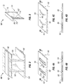
- FIGS. 4A-4D some aspects of non-limiting examples of vane tip platform segment 62 and vane hub platform segment 64 are depicted in accordance with an embodiment of the present invention.
- FIGS. 4A and 4B depict top and sectional views, respectively, of vane tip platform segment 62
- FIGS. 4C and 4D depict top and sectional views, respectively, of vane hub platform segment 64.
- Vane tip platform segment 62 includes openings 84.
- Vane hub platform segment 64 includes openings 86. Openings 84 and 86 are configured to position vanes 58 within doublet 60 and vane stage 50.
- openings 84 and 86 have the same airfoil cross-sectional shape 76 as body 70 of vane 58, i.e., the shape of extensions 78 and 82 (and lip 90 for embodiments so equipped). In other embodiments, openings 84 and 86 may take other forms.
- Each opening 84 is configured to receive a tip portion 72 of a vane 58, in particular, extension 78 and lip 80.
- Lip 80 is configured to retain vane 58 with vane tip platform segment 62.
- Openings 84 include a ledge 88. Ledge 88 is configured to function as a mating surface for the bottom of lip 80 to retain each vane 58 in vane tip platform segment 62.
- Each opening 86 is configured to receive a hub portion 74 of a vane 58, in particular, extension 82.
- vanes 58 are inserted into openings 84 and 86, in particular, extension 78 and lip 80, and extension 82, and are fastened into place using the paste adhesive, and tip and hub straps 66 and 68 are fastened to the ends of vanes 58, and to vane tip platform segment 62 and vane hub platform segment 64 using the paste adhesive, forming doublets 60.
- the number of openings 84 and 86 in vane tip platform segment 62 and vane hub platform segment 64 may vary in different embodiments.
- the number of openings 84 and 86 in vane tip platform segment 62 and vane hub platform segment 64 is sufficient to accommodate two vanes 58 in doublet 60.
- the number of openings 84 and 86 in vane tip platform segment 62 and vane hub platform segment 64 is sufficient to accommodate a single vane 58 or three vanes 58, respectively, e.g., as depicted in FIGS. 5A and 5B with vane hub platform segments 64A and 64B, respectively.
- the number of openings 84 and 86 in vane tip platform segment 62 and vane hub platform segment 64, and the number of vanes 58 in each vane ring segment may vary with the needs of the application.
- the combined number of openings in each of the vane tip platform segments 62 and vane hub platform segments 64 used to form vane stage 50 is selected to be sufficient to accommodate the total number of vanes 58 employed in vane stage 50.
- Openings 84 and 86 are formed to vary in one or more of an axial direction 90, a circumferential direction 92 and a setting angle direction 94, so that the position of some openings 84 and 86 vary in one or more of axial direction 90, circumferential direction 92 and setting angle direction 94, relative to other openings 84 and 86.
- the positions of openings 84 and 86 vary cyclically (in one or more of axial direction 90, circumferential direction 92 and setting angle direction 94) along circumferential direction 92, e.g., in order to mitigate the effects of struts 52 on bypass airflow, as schematically depicted in FIG. 6 , which schematically illustrates a plurality of openings 86 in circumferential hub platform 56 formed of a plurality of vane hub platform segments 64. It will be understood that the variation as between openings 86 illustrated in FIG.
- Embodiments of the present invention include a vane system for a gas turbine engine, comprising: a plurality of vanes, each vane being defined by the same dimensions, wherein each vane includes a first portion and a second portion; a first circumferential vane platform having a plurality of openings corresponding in number to the plurality of vanes, wherein each opening is configured to receive the first portion of one of the vanes; a second circumferential vane platform spaced radially apart from the first circumferential vane platform, wherein the second circumferential vane platform is configured to support the second portion of each of the vanes, wherein some of the plurality of openings vary in position relative to others of the plurality of openings.
- the some of the plurality of openings vary in an axial direction relative to the others of the plurality of openings.
- the some of the plurality of openings vary in a circumferential direction relative to the others of the plurality of openings.
- the some of the plurality of openings vary in a setting angle direction relative to the others of the plurality of openings.
- the some of the plurality of openings vary cyclically in a circumferential direction relative to the others of the plurality of openings.
- the first circumferential vane platform is a ring formed of a plurality of platform segments, each segment including one of the openings.
- the first circumferential vane platform is a ring formed of a plurality of platform segments, each segment including two of the openings.
- the first circumferential vane platform is a ring formed of a plurality of platform segments, each segment including three of the openings.
- the plurality of vanes are formed of a composite material.
- each vane has a same cross-sectional shape, and wherein each opening has the same cross-sectional shape as each vane.
- Embodiments of the present invention include a gas turbine engine, comprising: a fan blade stage; and a bypass vane stage disposed proximate to the fan blade stage and operative to direct air to or from the fan blade stage, wherein the bypass vane stage includes: a plurality of composite vanes, each vane being defined by the same dimensions; and a plurality of composite vane platform segments having a combined plurality of openings, wherein each vane platform segment includes at least one of the openings; wherein each opening is configured to receive a portion of one of the vanes and to position the one of the vanes within the bypass vane stage; wherein the plurality of vane platform segments are configured to jointly form a ring to form at least part of the bypass vane stage in conjunction with the vanes positioned by the openings; and wherein at least some of the openings vary in position relative to others of the openings.
- each vane platform segment includes at least two of the openings.
- each vane platform segment includes at least three of the openings.
- each vane includes an extension configured to be received in one of the openings.
- the extension includes a lip configured to retain the vane with one of the vane platform segments.
- the extension has an airfoil shape, and wherein each opening has the same airfoil shape as the extension.
- Embodiments of the present invention include a method of manufacturing a bypass vane stage, comprising: molding a plurality of composite vanes, each vane being defined by the same dimensions; forming a plurality of composite vane platform segments configured to jointly form a ring; forming a plurality of openings in the plurality of composite vane platform segments, wherein each vane platform segment includes at least one opening; and wherein each opening is formed to receive a portion of one of the vanes and to position the one of the vanes within the bypass vane stage; and wherein at least some of the openings are formed to vary in position relative to others of the openings.
- the at least some of the openings are formed to vary in one or more of an axial direction, a circumferential direction and a setting angle direction relative to the others of the openings.
- the method further comprises forming an extension in each vane configured to be received in one of the openings.
- the method further comprises forming a lip on the extension, wherein the lip is configured to retain the vane with one of the vane platform segments.
- the method further comprises: inserting one of the vanes into one of the openings; fastening the vane to one of the vane platform segments using a paste adhesive; and fastening a strap to the vane platform segment and an extension of the vane using the paste adhesive.
Landscapes
- Engineering & Computer Science (AREA)
- Mechanical Engineering (AREA)
- General Engineering & Computer Science (AREA)
- Chemical & Material Sciences (AREA)
- Combustion & Propulsion (AREA)
- Structures Of Non-Positive Displacement Pumps (AREA)
Claims (15)
- Bypassschaufelsystem für einen Gasturbinenmotor, umfassend:eine Vielzahl von Schaufeln (58), wobei jede Schaufel durch dieselben Abmessungen definiert wird, wobei jede Schaufel einen ersten Abschnitt (72) und einen zweiten Abschnitt (74) aufweist;eine erste umlaufende Schaufelplattform (54) mit einer Vielzahl von Öffnungen (84), die in der Zahl der Vielzahl von Schaufeln entsprechen, wobei jede Öffnung konfiguriert wird, um den ersten Abschnitt einer der Schaufeln aufzunehmen, wobei die erste umlaufende Schaufelplattform ein Schaufelplattformsegment (62) aufweist, das mindestens eine der Vielzahl von Öffnungen definiert; undeine von der ersten umlaufenden Schaufelplattform radial mit Abstand angeordnete zweite umlaufende Schaufelplattform (56), wobei die zweite umlaufende Schaufelplattform konfiguriert wird, um den zweiten Abschnitt jeder der Schaufeln zu tragen, wobei ein Teil der Vielzahl von Öffnungen in der Position bezogen auf andere der Vielzahl von Öffnungen variiert; wobei der erste Abschnitt jeder Schaufel eine Kante (80) aufweist, die sich davon ausdehnt; undeine in jeder Öffnung angeordnete Leiste (88); wobei, wenn jede Schaufel in einer entsprechenden der Öffnungen aufgenommen wird, eine Unterseite der Kante einer solchen Schaufel auf der in der entsprechenden der Öffnungen angeordneten Leiste aufliegt, und eine der Unterseite der Kante gegenüberliegende Oberseite der Kante sich nicht auswärts über eine Oberseite des Schaufelplattformsegments hinaus ausdehnt.
- Schaufelsystem nach Anspruch 1, wobei:(i) ein Teil der Vielzahl von Öffnungen (84) in einer Axialrichtung bezogen auf die anderen der Vielzahl von Öffnungen variiert; oder(ii) ein Teil der Vielzahl von Öffnungen (84) in einer Umfangsrichtung bezogen auf die anderen der Vielzahl von Öffnungen variiert; oder(iii) ein Teil der Vielzahl von Öffnungen (84) in einer Einstellwinkelrichtung bezogen auf die anderen der Vielzahl von Öffnungen variiert; oder(iv) ein Teil der Vielzahl von Öffnungen (84) in einer Umfangsrichtung bezogen auf die anderen der Vielzahl von Öffnungen zyklisch variiert; oder(v) die erste umlaufende Schaufelplattform (54) ein Ring ist, der aus einer Vielzahl der Plattformsegmente (62) gebildet wird, wobei jedes Segment eine der Öffnungen (84) aufweist; oder(vi) die erste umlaufende Schaufelplattform (54) ein Ring ist, der aus einer Vielzahl der Plattformsegmente (62) gebildet wird, wobei jedes Segment zwei der Öffnungen (84) aufweist.
- Schaufelsystem nach Anspruch 1, wobei die erste umlaufende Schaufelplattform (54) ein Ring ist, der aus einer Vielzahl der Plattformsegmente (62) gebildet wird, wobei jedes Segment drei der Öffnungen (84) aufweist.
- Schaufelsystem nach Anspruch 1, wobei die Vielzahl von Schaufeln (58) aus einem Verbundwerkstoff gebildet werden.
- Schaufelsystem nach Anspruch 1, wobei jede Schaufel (58) eine selbe Querschnittsform aufweist, und wobei jede Öffnung (84) und die Leiste (88) sich verbinden, um dieselbe Querschnittsform wie jede Schaufel zu bilden.
- Gasturbinenmotor, umfassend:eine Lüfterschaufelstufe (12); undeine Bypassschaufelstufe (50), die nahe der Lüfterschaufelstufe (12) angeordnet wird und Luft zu oder von der Lüfterschaufelstufe (12) leitet, wobei die Bypassschaufelstufe (50) aufweist:das Schaufelsystem nach Anspruch 1; undeine Vielzahl der Schaufelplattformsegmente (62); wobei die Vielzahl von Schaufelplattformsegmenten konfiguriert werden, um gemeinsam einen Ring zu bilden, um mindestens einen Teil der Bypassschaufelstufe (50) in Verbindung mit den Schaufeln (58) zu bilden, die durch die Öffnungen (84) positioniert werden.
- Gasturbinenmotor nach Anspruch 6, wobei jedes Schaufelplattformsegment (62) mindestens zwei der Öffnungen (84) aufweist.
- Gasturbinenmotor nach Anspruch 6, wobei jedes Schaufelplattformsegment (62) mindestens drei der Öffnungen (84) aufweist.
- Gasturbinenmotor nach Anspruch 6 bis 8, wobei jede Schaufel (58) eine Verlängerung (78) aufweist, die konfiguriert wird, um in einer der Öffnungen (84) aufgenommen zu werden.
- Gasturbinenmotor nach Anspruch 9, wobei die Verlängerung (78) die Kante (80) aufweist, die konfiguriert wird, um die Schaufel (58) mit einem der Schaufelplattformsegmente (62) zu halten.
- Gasturbinenmotor nach Anspruch 9, wobei die Verlängerung (78) eine Tragflächenform aufweist, und wobei jede Öffnung (84) dieselbe Tragflächenform wie die Verlängerung aufweist.
- Verfahren zum Herstellen einer Bypassschaufelstufe, umfassend:ein Formen einer Vielzahl von Verbundwerkstoffschaufeln (58), wobei jede Schaufel durch dieselben Abmessungen definiert wird und eine Kante (80) aufweist, die sich davon ausdehnt;ein Bilden einer Vielzahl von Schaufelplattformsegmente (62; 64) aus Verbundwerkstoff, die konfiguriert werden, gemeinsam einen Ring zu bilden;ein Bilden einer Vielzahl von Öffnungen (84; 86) in der Vielzahl von Schaufelplattformsegmenten aus Verbundwerkstoff,wobei jedes Schaufelplattformsegment mindestens eine Öffnung (84; 86) aufweist; und wobei jede Öffnung gebildet wird, um einen Abschnitt (70; 74) einer der Schaufeln (58) aufzunehmen und die eine der Schaufeln (58) innerhalb der Bypassschaufelstufe (50) zu positionieren; undwobei mindestens ein Teil der Öffnungen gebildet wird, um in einer Position bezogen auf andere der Öffnungen zu variieren; undein Bilden einer Leiste (88) in mindestens einer der Vielzahl von Öffnungen (84), wobei,wenn jede Schaufel in einer entsprechenden der Öffnungen (84) aufgenommen wird, eine Unterseite der Kante einer solchen Schaufel auf der in der entsprechenden der Öffnungen (84) angeordneten Leiste aufliegt; undeine der Unterseite der Kante gegenüberliegende Oberseite der Kante sich nicht auswärts über eine Oberseite des Schaufelplattformsegments (62) hinaus ausdehnt.
- Verfahren nach Anspruch 12, wobei mindestens ein Teil der Öffnungen (84, 86) gebildet wird, in einer oder mehreren einer Axialrichtung, einer Umfangsrichtung und einer Einstellwinkelrichtung bezogen auf die anderen der Öffnungen zu variieren.
- Verfahren nach Anspruch 12, das des Weiteren umfasst:ein Bilden einer Verlängerung (78) in jeder Schaufel (58), die konfiguriert wird, um in einer der Öffnungen (84) aufgenommen zu werden; undein Bilden einer Kante (80) auf der Verlängerung, wobei die Kante konfiguriert wird, die Schaufelplattformsegmente (62) zu halten.
- Verfahren nach Anspruch 12, das des Weiteren umfasst:ein Einsetzen einer der Schaufeln (58) in eine der Öffnungen (84; 86);ein Befestigen der Schaufelplattformsegmente (62; 64) durch Verwenden einer Klebstoffpaste; undein Befestigen eines Riemens (66; 68) an das Schaufelplattformsegment und eine Verlängerung (80; 82) der Schaufel durch Verwenden der Klebstoffpaste.
Applications Claiming Priority (2)
| Application Number | Priority Date | Filing Date | Title |
|---|---|---|---|
| US201161581786P | 2011-12-30 | 2011-12-30 | |
| PCT/US2012/072232 WO2013141941A1 (en) | 2011-12-30 | 2012-12-30 | Turbine engine and vane system |
Publications (3)
| Publication Number | Publication Date |
|---|---|
| EP2805022A1 EP2805022A1 (de) | 2014-11-26 |
| EP2805022A4 EP2805022A4 (de) | 2016-01-06 |
| EP2805022B1 true EP2805022B1 (de) | 2018-11-07 |
Family
ID=49223151
Family Applications (1)
| Application Number | Title | Priority Date | Filing Date |
|---|---|---|---|
| EP12871724.6A Active EP2805022B1 (de) | 2011-12-30 | 2012-12-30 | Gasturbinen Bypass-Leitschaufelsystem, Gasturbine und Herstellungsverfahren einer Beipass-Leitschaufelstufe |
Country Status (3)
| Country | Link |
|---|---|
| US (1) | US20140314548A1 (de) |
| EP (1) | EP2805022B1 (de) |
| WO (1) | WO2013141941A1 (de) |
Families Citing this family (19)
| Publication number | Priority date | Publication date | Assignee | Title |
|---|---|---|---|---|
| EP2966264B1 (de) * | 2014-07-07 | 2021-09-22 | Safran Aero Boosters SA | Laufradschaufelsegment eines Verdichters eines axialen Turbotriebwerks |
| US10738791B2 (en) * | 2015-12-16 | 2020-08-11 | General Electric Company | Active high pressure compressor clearance control |
| US10215194B2 (en) | 2015-12-21 | 2019-02-26 | Pratt & Whitney Canada Corp. | Mistuned fan |
| CA2958459C (en) | 2016-02-19 | 2025-07-08 | Pratt & Whitney Canada Corp. | COMPRESSOR ROTOR INTENDED FOR SUPERSONIC BUTTERFLY OR RESONANT STRESS REDUCTION |
| US10458436B2 (en) | 2017-03-22 | 2019-10-29 | Pratt & Whitney Canada Corp. | Fan rotor with flow induced resonance control |
| US10480535B2 (en) | 2017-03-22 | 2019-11-19 | Pratt & Whitney Canada Corp. | Fan rotor with flow induced resonance control |
| US10823203B2 (en) | 2017-03-22 | 2020-11-03 | Pratt & Whitney Canada Corp. | Fan rotor with flow induced resonance control |
| US11933223B2 (en) * | 2019-04-18 | 2024-03-19 | Rtx Corporation | Integrated additive fuel injectors for attritable engines |
| US11692488B2 (en) | 2020-11-04 | 2023-07-04 | Delavan Inc. | Torch igniter cooling system |
| US11608783B2 (en) | 2020-11-04 | 2023-03-21 | Delavan, Inc. | Surface igniter cooling system |
| US11473505B2 (en) | 2020-11-04 | 2022-10-18 | Delavan Inc. | Torch igniter cooling system |
| US11635027B2 (en) | 2020-11-18 | 2023-04-25 | Collins Engine Nozzles, Inc. | Fuel systems for torch ignition devices |
| US11421602B2 (en) * | 2020-12-16 | 2022-08-23 | Delavan Inc. | Continuous ignition device exhaust manifold |
| US12092333B2 (en) | 2020-12-17 | 2024-09-17 | Collins Engine Nozzles, Inc. | Radially oriented internally mounted continuous ignition device |
| US11754289B2 (en) | 2020-12-17 | 2023-09-12 | Delavan, Inc. | Axially oriented internally mounted continuous ignition device: removable nozzle |
| US11635210B2 (en) | 2020-12-17 | 2023-04-25 | Collins Engine Nozzles, Inc. | Conformal and flexible woven heat shields for gas turbine engine components |
| US11209164B1 (en) | 2020-12-18 | 2021-12-28 | Delavan Inc. | Fuel injector systems for torch igniters |
| US11680528B2 (en) | 2020-12-18 | 2023-06-20 | Delavan Inc. | Internally-mounted torch igniters with removable igniter heads |
| BE1032788B1 (fr) * | 2024-07-17 | 2026-02-17 | Safran Aero Boosters | Calage inhomogène d’aubes d’un stator d’une turbomachine d’aéronef |
Citations (1)
| Publication number | Priority date | Publication date | Assignee | Title |
|---|---|---|---|---|
| US20110033285A1 (en) * | 2008-12-29 | 2011-02-10 | Techspace Aero | Assembly for a stator stage of a turbomachine, the assembly comprising an outer shroud and at least one stationary vane |
Family Cites Families (12)
| Publication number | Priority date | Publication date | Assignee | Title |
|---|---|---|---|---|
| FR2600379B1 (fr) * | 1986-06-18 | 1988-09-02 | Snecma | Redresseur de soufflante de turboreacteur multiflux |
| FR2654463A1 (fr) * | 1989-11-15 | 1991-05-17 | Snecma | Element de stator de turbomachine. |
| US5494404A (en) * | 1993-12-22 | 1996-02-27 | Alliedsignal Inc. | Insertable stator vane assembly |
| JP4060981B2 (ja) * | 1998-04-08 | 2008-03-12 | 本田技研工業株式会社 | ガスタービンの静翼構造体及びそのユニット |
| US6554564B1 (en) * | 2001-11-14 | 2003-04-29 | United Technologies Corporation | Reduced noise fan exit guide vane configuration for turbofan engines |
| US6648597B1 (en) * | 2002-05-31 | 2003-11-18 | Siemens Westinghouse Power Corporation | Ceramic matrix composite turbine vane |
| GB2401654B (en) * | 2003-05-14 | 2006-04-19 | Rolls Royce Plc | A stator vane assembly for a turbomachine |
| US6905303B2 (en) * | 2003-06-30 | 2005-06-14 | General Electric Company | Methods and apparatus for assembling gas turbine engines |
| GB2427900B (en) * | 2005-07-02 | 2007-10-10 | Rolls Royce Plc | Vane support in a gas turbine engine |
| US8348604B2 (en) * | 2008-03-17 | 2013-01-08 | Rolls-Royce Corporation | Airfoil assembly and method of forming same |
| US8454303B2 (en) * | 2010-01-14 | 2013-06-04 | General Electric Company | Turbine nozzle assembly |
| EP2371521B1 (de) * | 2010-04-02 | 2014-07-02 | Techspace Aero S.A. | Verfahren zur Herstellung eines Gleichrichters |
-
2012
- 2012-12-30 WO PCT/US2012/072232 patent/WO2013141941A1/en not_active Ceased
- 2012-12-30 EP EP12871724.6A patent/EP2805022B1/de active Active
-
2014
- 2014-06-30 US US14/319,702 patent/US20140314548A1/en not_active Abandoned
Patent Citations (1)
| Publication number | Priority date | Publication date | Assignee | Title |
|---|---|---|---|---|
| US20110033285A1 (en) * | 2008-12-29 | 2011-02-10 | Techspace Aero | Assembly for a stator stage of a turbomachine, the assembly comprising an outer shroud and at least one stationary vane |
Also Published As
| Publication number | Publication date |
|---|---|
| WO2013141941A1 (en) | 2013-09-26 |
| US20140314548A1 (en) | 2014-10-23 |
| EP2805022A1 (de) | 2014-11-26 |
| EP2805022A4 (de) | 2016-01-06 |
Similar Documents
| Publication | Publication Date | Title |
|---|---|---|
| US20140314548A1 (en) | Turbine engine and vane system | |
| EP2472062B1 (de) | Fluggasturbine und Schaufel | |
| EP2472066B1 (de) | Verstellbare Statorbeschaufelung für Gasturbinentriebwerk, sowie zugehöriges Gasturbinentriebwerk | |
| EP3450727B1 (de) | Gasturbinentriebwerk | |
| US10914240B2 (en) | Gas turbine | |
| US20140311164A1 (en) | Gas turbine engine and turbine blade | |
| US12535007B2 (en) | Cover plate connections for a hollow fan blade | |
| US20140311163A1 (en) | Method of manufacturing a turbomachine component, an airfoil and a gas turbine engine | |
| EP2809882B1 (de) | Entlüftungsmuschel für eine kompressorscheibe | |
| US20260078682A1 (en) | Gas turbine engine | |
| EP2964904B1 (de) | Gasturbinenmotor | |
| US20120167572A1 (en) | Gas turbine engine and diffuser | |
| EP2472064A2 (de) | Schaufel für Gasturbinenmotore | |
| US10415591B2 (en) | Gas turbine engine airfoil | |
| US11066959B2 (en) | Geared turbofan gas turbine engine mounting arrangement | |
| EP3170973B1 (de) | Strömungskanal eines turbinenmotors | |
| US10711648B2 (en) | Nosecone support |
Legal Events
| Date | Code | Title | Description |
|---|---|---|---|
| PUAI | Public reference made under article 153(3) epc to a published international application that has entered the european phase |
Free format text: ORIGINAL CODE: 0009012 |
|
| 17P | Request for examination filed |
Effective date: 20140728 |
|
| AK | Designated contracting states |
Kind code of ref document: A1 Designated state(s): AL AT BE BG CH CY CZ DE DK EE ES FI FR GB GR HR HU IE IS IT LI LT LU LV MC MK MT NL NO PL PT RO RS SE SI SK SM TR |
|
| DAX | Request for extension of the european patent (deleted) | ||
| RA4 | Supplementary search report drawn up and despatched (corrected) |
Effective date: 20151204 |
|
| RIC1 | Information provided on ipc code assigned before grant |
Ipc: F01D 9/00 20060101AFI20151130BHEP Ipc: F01D 9/04 20060101ALI20151130BHEP Ipc: F02K 3/075 20060101ALI20151130BHEP Ipc: F01D 17/10 20060101ALI20151130BHEP |
|
| GRAP | Despatch of communication of intention to grant a patent |
Free format text: ORIGINAL CODE: EPIDOSNIGR1 |
|
| INTG | Intention to grant announced |
Effective date: 20180608 |
|
| GRAS | Grant fee paid |
Free format text: ORIGINAL CODE: EPIDOSNIGR3 |
|
| GRAA | (expected) grant |
Free format text: ORIGINAL CODE: 0009210 |
|
| AK | Designated contracting states |
Kind code of ref document: B1 Designated state(s): AL AT BE BG CH CY CZ DE DK EE ES FI FR GB GR HR HU IE IS IT LI LT LU LV MC MK MT NL NO PL PT RO RS SE SI SK SM TR |
|
| REG | Reference to a national code |
Ref country code: GB Ref legal event code: FG4D |
|
| REG | Reference to a national code |
Ref country code: CH Ref legal event code: EP Ref country code: AT Ref legal event code: REF Ref document number: 1062294 Country of ref document: AT Kind code of ref document: T Effective date: 20181115 |
|
| REG | Reference to a national code |
Ref country code: IE Ref legal event code: FG4D |
|
| REG | Reference to a national code |
Ref country code: DE Ref legal event code: R096 Ref document number: 602012053331 Country of ref document: DE |
|
| RAP2 | Party data changed (patent owner data changed or rights of a patent transferred) |
Owner name: ROLLS-ROYCE CORPORATION |
|
| REG | Reference to a national code |
Ref country code: NL Ref legal event code: MP Effective date: 20181107 |
|
| REG | Reference to a national code |
Ref country code: LT Ref legal event code: MG4D |
|
| REG | Reference to a national code |
Ref country code: AT Ref legal event code: MK05 Ref document number: 1062294 Country of ref document: AT Kind code of ref document: T Effective date: 20181107 |
|
| PG25 | Lapsed in a contracting state [announced via postgrant information from national office to epo] |
Ref country code: LT Free format text: LAPSE BECAUSE OF FAILURE TO SUBMIT A TRANSLATION OF THE DESCRIPTION OR TO PAY THE FEE WITHIN THE PRESCRIBED TIME-LIMIT Effective date: 20181107 Ref country code: BG Free format text: LAPSE BECAUSE OF FAILURE TO SUBMIT A TRANSLATION OF THE DESCRIPTION OR TO PAY THE FEE WITHIN THE PRESCRIBED TIME-LIMIT Effective date: 20190207 Ref country code: NO Free format text: LAPSE BECAUSE OF FAILURE TO SUBMIT A TRANSLATION OF THE DESCRIPTION OR TO PAY THE FEE WITHIN THE PRESCRIBED TIME-LIMIT Effective date: 20190207 Ref country code: FI Free format text: LAPSE BECAUSE OF FAILURE TO SUBMIT A TRANSLATION OF THE DESCRIPTION OR TO PAY THE FEE WITHIN THE PRESCRIBED TIME-LIMIT Effective date: 20181107 Ref country code: LV Free format text: LAPSE BECAUSE OF FAILURE TO SUBMIT A TRANSLATION OF THE DESCRIPTION OR TO PAY THE FEE WITHIN THE PRESCRIBED TIME-LIMIT Effective date: 20181107 Ref country code: HR Free format text: LAPSE BECAUSE OF FAILURE TO SUBMIT A TRANSLATION OF THE DESCRIPTION OR TO PAY THE FEE WITHIN THE PRESCRIBED TIME-LIMIT Effective date: 20181107 Ref country code: ES Free format text: LAPSE BECAUSE OF FAILURE TO SUBMIT A TRANSLATION OF THE DESCRIPTION OR TO PAY THE FEE WITHIN THE PRESCRIBED TIME-LIMIT Effective date: 20181107 Ref country code: IS Free format text: LAPSE BECAUSE OF FAILURE TO SUBMIT A TRANSLATION OF THE DESCRIPTION OR TO PAY THE FEE WITHIN THE PRESCRIBED TIME-LIMIT Effective date: 20190307 Ref country code: AT Free format text: LAPSE BECAUSE OF FAILURE TO SUBMIT A TRANSLATION OF THE DESCRIPTION OR TO PAY THE FEE WITHIN THE PRESCRIBED TIME-LIMIT Effective date: 20181107 |
|
| PG25 | Lapsed in a contracting state [announced via postgrant information from national office to epo] |
Ref country code: GR Free format text: LAPSE BECAUSE OF FAILURE TO SUBMIT A TRANSLATION OF THE DESCRIPTION OR TO PAY THE FEE WITHIN THE PRESCRIBED TIME-LIMIT Effective date: 20190208 Ref country code: PT Free format text: LAPSE BECAUSE OF FAILURE TO SUBMIT A TRANSLATION OF THE DESCRIPTION OR TO PAY THE FEE WITHIN THE PRESCRIBED TIME-LIMIT Effective date: 20190307 Ref country code: RS Free format text: LAPSE BECAUSE OF FAILURE TO SUBMIT A TRANSLATION OF THE DESCRIPTION OR TO PAY THE FEE WITHIN THE PRESCRIBED TIME-LIMIT Effective date: 20181107 Ref country code: SE Free format text: LAPSE BECAUSE OF FAILURE TO SUBMIT A TRANSLATION OF THE DESCRIPTION OR TO PAY THE FEE WITHIN THE PRESCRIBED TIME-LIMIT Effective date: 20181107 Ref country code: NL Free format text: LAPSE BECAUSE OF FAILURE TO SUBMIT A TRANSLATION OF THE DESCRIPTION OR TO PAY THE FEE WITHIN THE PRESCRIBED TIME-LIMIT Effective date: 20181107 Ref country code: AL Free format text: LAPSE BECAUSE OF FAILURE TO SUBMIT A TRANSLATION OF THE DESCRIPTION OR TO PAY THE FEE WITHIN THE PRESCRIBED TIME-LIMIT Effective date: 20181107 |
|
| PG25 | Lapsed in a contracting state [announced via postgrant information from national office to epo] |
Ref country code: PL Free format text: LAPSE BECAUSE OF FAILURE TO SUBMIT A TRANSLATION OF THE DESCRIPTION OR TO PAY THE FEE WITHIN THE PRESCRIBED TIME-LIMIT Effective date: 20181107 Ref country code: IT Free format text: LAPSE BECAUSE OF FAILURE TO SUBMIT A TRANSLATION OF THE DESCRIPTION OR TO PAY THE FEE WITHIN THE PRESCRIBED TIME-LIMIT Effective date: 20181107 Ref country code: DK Free format text: LAPSE BECAUSE OF FAILURE TO SUBMIT A TRANSLATION OF THE DESCRIPTION OR TO PAY THE FEE WITHIN THE PRESCRIBED TIME-LIMIT Effective date: 20181107 Ref country code: CZ Free format text: LAPSE BECAUSE OF FAILURE TO SUBMIT A TRANSLATION OF THE DESCRIPTION OR TO PAY THE FEE WITHIN THE PRESCRIBED TIME-LIMIT Effective date: 20181107 |
|
| REG | Reference to a national code |
Ref country code: CH Ref legal event code: PL |
|
| REG | Reference to a national code |
Ref country code: DE Ref legal event code: R097 Ref document number: 602012053331 Country of ref document: DE |
|
| PG25 | Lapsed in a contracting state [announced via postgrant information from national office to epo] |
Ref country code: LU Free format text: LAPSE BECAUSE OF NON-PAYMENT OF DUE FEES Effective date: 20181230 Ref country code: SK Free format text: LAPSE BECAUSE OF FAILURE TO SUBMIT A TRANSLATION OF THE DESCRIPTION OR TO PAY THE FEE WITHIN THE PRESCRIBED TIME-LIMIT Effective date: 20181107 Ref country code: MC Free format text: LAPSE BECAUSE OF FAILURE TO SUBMIT A TRANSLATION OF THE DESCRIPTION OR TO PAY THE FEE WITHIN THE PRESCRIBED TIME-LIMIT Effective date: 20181107 Ref country code: SM Free format text: LAPSE BECAUSE OF FAILURE TO SUBMIT A TRANSLATION OF THE DESCRIPTION OR TO PAY THE FEE WITHIN THE PRESCRIBED TIME-LIMIT Effective date: 20181107 Ref country code: RO Free format text: LAPSE BECAUSE OF FAILURE TO SUBMIT A TRANSLATION OF THE DESCRIPTION OR TO PAY THE FEE WITHIN THE PRESCRIBED TIME-LIMIT Effective date: 20181107 Ref country code: EE Free format text: LAPSE BECAUSE OF FAILURE TO SUBMIT A TRANSLATION OF THE DESCRIPTION OR TO PAY THE FEE WITHIN THE PRESCRIBED TIME-LIMIT Effective date: 20181107 |
|
| PLBE | No opposition filed within time limit |
Free format text: ORIGINAL CODE: 0009261 |
|
| STAA | Information on the status of an ep patent application or granted ep patent |
Free format text: STATUS: NO OPPOSITION FILED WITHIN TIME LIMIT |
|
| REG | Reference to a national code |
Ref country code: BE Ref legal event code: MM Effective date: 20181231 Ref country code: IE Ref legal event code: MM4A |
|
| 26N | No opposition filed |
Effective date: 20190808 |
|
| GBPC | Gb: european patent ceased through non-payment of renewal fee |
Effective date: 20190207 |
|
| PG25 | Lapsed in a contracting state [announced via postgrant information from national office to epo] |
Ref country code: IE Free format text: LAPSE BECAUSE OF NON-PAYMENT OF DUE FEES Effective date: 20181230 Ref country code: SI Free format text: LAPSE BECAUSE OF FAILURE TO SUBMIT A TRANSLATION OF THE DESCRIPTION OR TO PAY THE FEE WITHIN THE PRESCRIBED TIME-LIMIT Effective date: 20181107 |
|
| PG25 | Lapsed in a contracting state [announced via postgrant information from national office to epo] |
Ref country code: BE Free format text: LAPSE BECAUSE OF NON-PAYMENT OF DUE FEES Effective date: 20181231 |
|
| PG25 | Lapsed in a contracting state [announced via postgrant information from national office to epo] |
Ref country code: CH Free format text: LAPSE BECAUSE OF NON-PAYMENT OF DUE FEES Effective date: 20181231 Ref country code: LI Free format text: LAPSE BECAUSE OF NON-PAYMENT OF DUE FEES Effective date: 20181231 |
|
| PG25 | Lapsed in a contracting state [announced via postgrant information from national office to epo] |
Ref country code: GB Free format text: LAPSE BECAUSE OF NON-PAYMENT OF DUE FEES Effective date: 20190207 Ref country code: MT Free format text: LAPSE BECAUSE OF NON-PAYMENT OF DUE FEES Effective date: 20181230 |
|
| PGFP | Annual fee paid to national office [announced via postgrant information from national office to epo] |
Ref country code: FR Payment date: 20191226 Year of fee payment: 8 |
|
| PG25 | Lapsed in a contracting state [announced via postgrant information from national office to epo] |
Ref country code: TR Free format text: LAPSE BECAUSE OF FAILURE TO SUBMIT A TRANSLATION OF THE DESCRIPTION OR TO PAY THE FEE WITHIN THE PRESCRIBED TIME-LIMIT Effective date: 20181107 |
|
| PG25 | Lapsed in a contracting state [announced via postgrant information from national office to epo] |
Ref country code: MK Free format text: LAPSE BECAUSE OF NON-PAYMENT OF DUE FEES Effective date: 20181107 Ref country code: CY Free format text: LAPSE BECAUSE OF FAILURE TO SUBMIT A TRANSLATION OF THE DESCRIPTION OR TO PAY THE FEE WITHIN THE PRESCRIBED TIME-LIMIT Effective date: 20181107 Ref country code: HU Free format text: LAPSE BECAUSE OF FAILURE TO SUBMIT A TRANSLATION OF THE DESCRIPTION OR TO PAY THE FEE WITHIN THE PRESCRIBED TIME-LIMIT; INVALID AB INITIO Effective date: 20121230 |
|
| PG25 | Lapsed in a contracting state [announced via postgrant information from national office to epo] |
Ref country code: FR Free format text: LAPSE BECAUSE OF NON-PAYMENT OF DUE FEES Effective date: 20201231 |
|
| P01 | Opt-out of the competence of the unified patent court (upc) registered |
Effective date: 20230528 |
|
| PGFP | Annual fee paid to national office [announced via postgrant information from national office to epo] |
Ref country code: DE Payment date: 20251229 Year of fee payment: 14 |