EP2804714B1 - Universal conduit assembly for a welding torch - Google Patents
Universal conduit assembly for a welding torch Download PDFInfo
- Publication number
- EP2804714B1 EP2804714B1 EP13703938.4A EP13703938A EP2804714B1 EP 2804714 B1 EP2804714 B1 EP 2804714B1 EP 13703938 A EP13703938 A EP 13703938A EP 2804714 B1 EP2804714 B1 EP 2804714B1
- Authority
- EP
- European Patent Office
- Prior art keywords
- conduit
- end portion
- tip
- stop
- universal
- Prior art date
- Legal status (The legal status is an assumption and is not a legal conclusion. Google has not performed a legal analysis and makes no representation as to the accuracy of the status listed.)
- Active
Links
Images



Classifications
-
- B—PERFORMING OPERATIONS; TRANSPORTING
- B23—MACHINE TOOLS; METAL-WORKING NOT OTHERWISE PROVIDED FOR
- B23K—SOLDERING OR UNSOLDERING; WELDING; CLADDING OR PLATING BY SOLDERING OR WELDING; CUTTING BY APPLYING HEAT LOCALLY, e.g. FLAME CUTTING; WORKING BY LASER BEAM
- B23K9/00—Arc welding or cutting
- B23K9/24—Features related to electrodes
-
- B—PERFORMING OPERATIONS; TRANSPORTING
- B23—MACHINE TOOLS; METAL-WORKING NOT OTHERWISE PROVIDED FOR
- B23K—SOLDERING OR UNSOLDERING; WELDING; CLADDING OR PLATING BY SOLDERING OR WELDING; CUTTING BY APPLYING HEAT LOCALLY, e.g. FLAME CUTTING; WORKING BY LASER BEAM
- B23K9/00—Arc welding or cutting
- B23K9/32—Accessories
- B23K9/323—Combined coupling means, e.g. gas, electricity, water or the like
Definitions
- the disclosure relates generally to arc welding torch systems and components used in arc welding torches. More specifically, the disclosure relates to a universal conduit assembly applicable to gas metal arc welding (GMAW) or metal inert gas (MIG) welding systems.
- GMAW gas metal arc welding
- MIG metal inert gas
- Gas metal arc welding (GMAW) or metal inert gas (MIG) welding utilize a metal wire to act as the electrode to produce an arc.
- the wire which is shielded by an inert gas, acts a filler or raw material that forms the weld.
- the wire and gas are fed through a welding gun positioned proximate to the desired location for the weld.
- the wire is fed to the gun through a conduit coupled to both a powered wire feeder and a gas flow regulation system.
- conduits consist of a coiled steel liner used to guide the welding wire and a brass connector that is crimped over the end of the conduit.
- the connector is designed to reversibly couple with the rear power plug of a torch or welding gun.
- the specific design of the connector is dependent upon the manufacturer of the welding gun because different manufacturers will differentiate their gun design from competitive products by using different plug geometries.
- US 2005/072764 A1 discloses a universal conduit assembly with the features of the preamble of claim 1.
- proximal refers to a position that is located towards the torch or gun handle
- distal refers to a position that is located towards the electrical power supply
- the present disclosure generally provides a universal conduit assembly for a welding torch comprising a conduit liner defining a proximal end portion and a distal end portion; a conduit tip secured to the proximal end portion of the conduit liner; and an interchangeable conduit stop reversibly secured to the conduit tip.
- the interchangeable conduit stop is adapted for connection to a specific OEM (Original Equipment Manufacturer) power connector.
- OEM OEM
- interchangeable conduit stops of the present disclosure are designed to resemble the conventional connector geometries used by different manufacturers. In Figure 1 , the connector geometries used by five common manufacturers, namely, Abicor Binzel USA (Frederick, MD) 1, Miller Electric Manufacturing Co. (Appleton, WI) 2, Tregaskiss (Ontario, Canada) 3, Bernard ITW (Beecher, IL) 4, and Thermadyne Industries - Tweco (St. Louis, Mo) 5 are shown.
- the conduit tip 10 defines a central bore 15 extending from a proximal end portion 25 to a distal end portion 20, and a chamfer 30 disposed around the central bore 15 at the distal end portion 20.
- the conduit tip 10 defines an internal shoulder 35 having a first end 31 and a second end 32.
- the internal shoulder 35 is open at the first end 31, while the second end 32 engages the chamfer 30.
- the presence of the chamfer 30 provides protection for the conduit liner 40 against the presence of any sharp edges existing at the distal end portion 20 of the conduit tip 10.
- the conduit tip 10 is sized in order for the internal shoulder 35 to accommodate the outer diameter of the conduit liner 40.
- the conduit liner 40 can be any type of conduit known to one skilled in the art of welding.
- the conduit liner 40 may include a polymer material 41, such as a shrink tubing material, disposed about a metal coiled conduit 42.
- the conduit tip 10 can be secured to the conduit liner 40 by any method known to one skilled in the art, including but not limited to crimping, press-fitting, and adhesive bonding.
- the conduit tip 10 further defines an external attachment area 50, which may be threaded as shown in Figure 2A .
- a conduit tip 10 according to another aspect of the present disclosure is shown in Figure 2B , where the external attachment area 50 is tapered, instead of being threaded.
- the angle of the taper is preferably about 1.5 degrees although one skilled-in-the-art will recognize that other taper angles may be used.
- the proximal end portion 25 of the conduit tip 10 may also include a chamfer 55 that encompasses the central bore 15.
- the purpose of the external attachment area 50 is to allow the conduit tip 10 to engage and become reversibly secured to a conduit stop.
- the means of attachment of the conduit tip 10 to a conduit stop is preferably one selected from the group of the meshing of threads, a taper lock, and a set screw.
- the means of attachment is through the use of threads or a set screw because the use of a taper connection sometimes makes the disassembly of the parts more difficult due to the strength of the interaction between the conduit tip 15 and conduit stop.
- the body of the conduit stop defines an internally threaded portion for engagement with the externally threaded portion of the conduit tip.
- the threads may comprise about a 30 degree angle at the start and the end of the threads.
- the universal conduit assembly 60 comprises a conduit stop 65, as well as the conduit tip 10 and conduit liner 40 as previously described with respect to Figures 2A and 2B .
- the conduit stop 65 and the conduit tip 10 engage one anther via the attachment area of the conduit tip 10.
- the proximal end portion 25 of the conduit tip 10 extends to and engages the proximal end portion 70 of the conduit stop 65.
- distal end portion 25 of the conduit tip 10 may extend past or beyond the proximal end portion 70 of the conduit stop 65 as shown in Figure 3C , where the distal end portion 25 of the conduit tip 15 extends to the distal end portion 75 of the conduit stop 65.
- the conduit stop 65 defines an internal shoulder 80 and the conduit tip 10 defines an external shoulder 85 such that the external shoulder 85 of the conduit tip 10 abuts the internal shoulder 80 of the conduit stop 65 to provide a metal-to-metal gas seal.
- the internal shoulder 80 may also provide for the proper positioning of the conduit tip 15 in order for engagement with the conduit stop 65 through its attachment area 50.
- the metal-to-metal gas seal may also be established by an angled shoulder 100 made by an indentation established in the body of the conduit stop 65 and a corresponding abutment established in the body of the conduit tip 15.
- the angle of the angled shoulder 100 is preferably about 118 degrees, although one skilled-in-the-art will recognize that other angles could be used.
- conduit liner 40 extends all the way to the distal end portion 75 of the conduit stop 65.
- a set screw 105 is used to secure the conduit stop 65 to the conduit liner 40. In this case, the presence of a conduit tip 15 is not necessary.
- the external shape of the conduit stop 65 is designed to substantially resemble a specific OEM power connector for use with a corresponding welding torch system.
- the conduit stop 65 comprises an external surface 87 that may engage the specific OEM power connector.
- the specific OEM power connector is preferably selected from the group consisting of Bernard, Miller, Tregaskiss, and Tweco connectors.
- the universal conduit assembly 60 may include a sealing element 90 disposed around an external surface 87 of the conduit stop 65.
- the conduit stop 65 may also optionally comprise a chamfer 95 at its distal end 75 in order to protect the welding wire from any sharp edges.
- the conduit liner 40 may comprise a polymer material 41 disposed around a metal coil or braided conduit 42.
- the metal coil conduit 42 may be comprised of a metal, such as, for example, aluminum, steel, copper, or a metal alloy, such as, for example, brass.
- the polymer material 41 may include, but not be limited to, any polymer that can provide electrical insulation and exhibit high thermal stability. Such a polymer material 41 is preferably available as a form of shrink wrap tubing.
- the conduit tip 15 and conduit stop 65 may be formed from a metal that exhibits good electrical conductivity. Examples of such metals include aluminum, brass, and copper.
- the conduit tip 15, conduit liner 40, and conduit stop 65 are each sized to accommodate the diameter size of the desired welding wire electrode selected for use.
- a different conduit tip 15, conduit liner 40, and conduit stop 65 may be required for each different wire size that may be used.
- Examples of several wires with their specified wire diameters include but are not limited to 3545 (0.89 mm to 1.14 mm) (0.035" to 0.045"), 116 (1.59 mm) (1/16"), 564 (1.98 mm) (5/64"), and 332 (2.38 mm) (3/32").
- a welding torch assembly 200 that comprises a welding gun handle 205; a welding cable 240 defining a proximal end portion 245 and a distal end portion 235, the welding cable 240 secured to the welding gun handle 205 at the proximal end portion 245; and a conduit assembly 260 disposed at the proximal end portion 245 of the welding cable 240.
- the conduit assembly 260 used for this welding torch assembly 200 is the universal conduit assembly 60 made by the teachings of the present disclosure.
- this conduit assembly 60 comprises a conduit liner 40 defining a proximal end portion 45 and a distal end portion; a conduit tip 15 secured to the proximal end portion 45 of the conduit liner 40; and an interchangeable conduit stop 65 removably secured to the conduit tip 15 with the interchangeable conduit stop 65 adapted for connection to a specific OEM power connector.
- the OEM power connector is typically part of the welding gun handle 205.
- a welding conduit kit 300 that comprises a conduit liner 340 defining a proximal end portion 345 and a distal end portion 335; a conduit tip 315 secured to the proximal end portion 345 of the conduit liner 340; and a plurality of interchangeable conduit stops 365 adapted for being removably secured to the conduit tip 315, the interchangeable conduit stops 365 adapted for connection to specific OEM power connectors.
- the specific OEM power connector is preferably selected from the group consisting of Tweco 361, Bernard 362, Miller 363, and Tregaskiss 364.
- Universal conduit assemblies 60 were prepared according to the teachings of the present disclosure to resemble the OEM power connectors manufactured by Tregaskiss, Bernard, Tweco, and Miller. These universal conduit assemblies 60 were connected to a corresponding welding torch and found to perform similarly to conventional OEM power connectors. A visual comparison between the universal adapter assemblies 60 and the corresponding OEM power connectors are provided in Figure 7 . More specifically, the universal adapter assemblies 60 of the present disclosure are labeled as trial #(1), while the specific OEM power connector sold by Tregaskiss ( Figure 7A ), Bernard ( Figure 7B ), Tweco ( Figure 7C ), and Miller ( Figure 7D ) are labeled as trial #(2).
Landscapes
- Engineering & Computer Science (AREA)
- Physics & Mathematics (AREA)
- Plasma & Fusion (AREA)
- Mechanical Engineering (AREA)
- Arc Welding In General (AREA)
- Butt Welding And Welding Of Specific Article (AREA)
- Joints Allowing Movement (AREA)
- Media Introduction/Drainage Providing Device (AREA)
- Non-Disconnectible Joints And Screw-Threaded Joints (AREA)
Description
- This application claims the benefit of provisional application serial no.
61/588,592, filed on January 19, 2012 - The disclosure relates generally to arc welding torch systems and components used in arc welding torches. More specifically, the disclosure relates to a universal conduit assembly applicable to gas metal arc welding (GMAW) or metal inert gas (MIG) welding systems.
- The statements in this section merely provide background information related to the present disclosure and may not constitute prior art.
- Gas metal arc welding (GMAW) or metal inert gas (MIG) welding utilize a metal wire to act as the electrode to produce an arc. The wire, which is shielded by an inert gas, acts a filler or raw material that forms the weld. Typically, the wire and gas are fed through a welding gun positioned proximate to the desired location for the weld. The wire is fed to the gun through a conduit coupled to both a powered wire feeder and a gas flow regulation system.
- Traditionally, conduits consist of a coiled steel liner used to guide the welding wire and a brass connector that is crimped over the end of the conduit. The connector is designed to reversibly couple with the rear power plug of a torch or welding gun. The specific design of the connector is dependent upon the manufacturer of the welding gun because different manufacturers will differentiate their gun design from competitive products by using different plug geometries.
- The different plug geometries utilized on different welding gun designs requires equipment distributors to stock a variety of conduits each having different end connectors in order to accommodate the various gun designs. For small distributors, the necessity of carrying a full line of conduits for each different welding gun is not economically feasible. In addition, end users of welding guns may use guns made by different manufacturers and are then limited to selecting a large distributor that can stock a full line of conduits for each welding gun or to use multiple distributors to service their equipment. In either case, the end-user is required to purchase and stock multiple conduit lines to service the various welding guns that they own.
-
US 2005/072764 A1 discloses a universal conduit assembly with the features of the preamble ofclaim 1. - The drawings described herein are for illustration purposes only and are not intended to limit the scope of the present disclosure in any way.
-
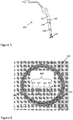
Figure 1 is a perspective view of conventional conduit connector geometries used by five welding gun manufacturers (A-E); -
Figure 2A is a cross-sectional view of a conduit tip and conduit liner prepared according to the teachings of the present disclosure; -
Figure 2B is a cross-sectional view of a conduit tip and conduit liner according to another aspect of the present disclosure; -
Figure 3A is a cross-sectional view of a universal conduit assembly according to the teachings of the present disclosure showing a conduit stop coupled with the conduit tip and liner ofFigure 2A ; -
Figure 3B is a cross-sectional view of another universal conduit assembly according to another aspect of the present disclosure showing a conduit stop coupled with the conduit tip and liner ofFigure 2B ; -
Figure 3C is a cross-sectional view of a universal conduit assembly according to another aspect of the present disclosure showing a conduit stop coupled with the conduit tip and liner ofFigure 2C ; -
Figure 4 is a cross-sectional view of a universal conduit assembly according to an embodiment that does not form part of the invention; -
Figure 5A is a perspective view comparing the geometric similarity between (1) a conventional conduit connector manufactured by Tregaskiss and (2) a universal conduit assembly prepared according to the teachings of the present disclosure; -
Figure 5B is a perspective view comparing the geometric similarity between (1) a conventional conduit connector manufactured by Bernard and (2) a universal conduit assembly prepared according to the teachings of the present disclosure; -
Figure 5C is a perspective view comparing the geometric similarity between (1) a conventional conduit connector manufactured by Tweco and (2) a universal conduit assembly prepared according to the teachings of the present disclosure; -
Figure 5D is a perspective view comparing the geometric similarity between (1) a conventional conduit connector manufactured by Miller and (2) a universal conduit assembly prepared according to the teachings of the present disclosure; -
Figure 6 is a schematic depicting a welding torch assembly according to one embodiment of the present disclosure; and -
Figure 7 is a perspective view of a welding conduit kit prepared according to the teachings of the present disclosure. - The following description is merely exemplary in nature and is in no way intended to limit the present disclosure or its application or uses. It should be understood that throughout the description and drawings, corresponding reference numerals indicate like or corresponding parts and features. As used throughout the description and claims, the term "proximal" refers to a position that is located towards the torch or gun handle, while the term "distal" refers to a position that is located towards the electrical power supply.
- The present disclosure generally provides a universal conduit assembly for a welding torch comprising a conduit liner defining a proximal end portion and a distal end portion; a conduit tip secured to the proximal end portion of the conduit liner; and an interchangeable conduit stop reversibly secured to the conduit tip. The interchangeable conduit stop is adapted for connection to a specific OEM (Original Equipment Manufacturer) power connector. For example, interchangeable conduit stops of the present disclosure are designed to resemble the conventional connector geometries used by different manufacturers. In
Figure 1 , the connector geometries used by five common manufacturers, namely, Abicor Binzel USA (Frederick, MD) 1, Miller Electric Manufacturing Co. (Appleton, WI) 2, Tregaskiss (Ontario, Canada) 3, Bernard ITW (Beecher, IL) 4, and Thermadyne Industries - Tweco (St. Louis, Mo) 5 are shown. - Referring to
Figure 2A , theconduit tip 10 defines acentral bore 15 extending from aproximal end portion 25 to adistal end portion 20, and achamfer 30 disposed around thecentral bore 15 at thedistal end portion 20. Theconduit tip 10 defines aninternal shoulder 35 having afirst end 31 and asecond end 32. Theinternal shoulder 35 is open at thefirst end 31, while thesecond end 32 engages thechamfer 30. - A
conduit liner 40 having aproximal end portion 45 and a distal end portion engages theinternal shoulder 35 where theproximal end portion 45 of theconduit liner 40 abuts thesecond end 32 of theinternal shoulder 35 and thechamfer 30. The presence of thechamfer 30 provides protection for theconduit liner 40 against the presence of any sharp edges existing at thedistal end portion 20 of theconduit tip 10. Theconduit tip 10 is sized in order for theinternal shoulder 35 to accommodate the outer diameter of theconduit liner 40. Theconduit liner 40 can be any type of conduit known to one skilled in the art of welding. Theconduit liner 40 may include apolymer material 41, such as a shrink tubing material, disposed about a metal coiledconduit 42. Theconduit tip 10 can be secured to theconduit liner 40 by any method known to one skilled in the art, including but not limited to crimping, press-fitting, and adhesive bonding. - The
conduit tip 10 further defines anexternal attachment area 50, which may be threaded as shown inFigure 2A . Aconduit tip 10 according to another aspect of the present disclosure is shown inFigure 2B , where theexternal attachment area 50 is tapered, instead of being threaded. The angle of the taper is preferably about 1.5 degrees although one skilled-in-the-art will recognize that other taper angles may be used. Referring toFigure 2B , theproximal end portion 25 of theconduit tip 10 may also include achamfer 55 that encompasses thecentral bore 15. The purpose of theexternal attachment area 50 is to allow theconduit tip 10 to engage and become reversibly secured to a conduit stop. The means of attachment of theconduit tip 10 to a conduit stop is preferably one selected from the group of the meshing of threads, a taper lock, and a set screw. Preferably, the means of attachment is through the use of threads or a set screw because the use of a taper connection sometimes makes the disassembly of the parts more difficult due to the strength of the interaction between theconduit tip 15 and conduit stop. The body of the conduit stop defines an internally threaded portion for engagement with the externally threaded portion of the conduit tip. In order to reduce the occurrence of burrs when a threadedexternal attachment area 50 is used, the threads may comprise about a 30 degree angle at the start and the end of the threads. - Referring now to
Figures 3A and 3B , auniversal conduit assembly 60 made according to the teachings of the present disclosure is shown. Theuniversal conduit assembly 60 comprises aconduit stop 65, as well as theconduit tip 10 andconduit liner 40 as previously described with respect toFigures 2A and 2B . Theconduit stop 65 and theconduit tip 10 engage one anther via the attachment area of theconduit tip 10. Preferably, theproximal end portion 25 of theconduit tip 10 extends to and engages theproximal end portion 70 of the conduit stop 65. One skilled-in-the-art will recognize that thedistal end portion 25 of theconduit tip 10 may extend past or beyond theproximal end portion 70 of the conduit stop 65 as shown inFigure 3C , where thedistal end portion 25 of theconduit tip 15 extends to thedistal end portion 75 of the conduit stop 65. - Referring again to
Figures 3A and 3B , the conduit stop 65 defines aninternal shoulder 80 and theconduit tip 10 defines anexternal shoulder 85 such that theexternal shoulder 85 of theconduit tip 10 abuts theinternal shoulder 80 of the conduit stop 65 to provide a metal-to-metal gas seal. Theinternal shoulder 80 may also provide for the proper positioning of theconduit tip 15 in order for engagement with the conduit stop 65 through itsattachment area 50. Referring now toFigure 3C , the metal-to-metal gas seal may also be established by anangled shoulder 100 made by an indentation established in the body of the conduit stop 65 and a corresponding abutment established in the body of theconduit tip 15. The angle of theangled shoulder 100 is preferably about 118 degrees, although one skilled-in-the-art will recognize that other angles could be used. - Referring now to
Figure 4 , auniversal conduit assembly 60 according to an embodiment that does not form part of the invention is presented. In this case, theconduit liner 40 extends all the way to thedistal end portion 75 of the conduit stop 65. Aset screw 105 is used to secure the conduit stop 65 to theconduit liner 40. In this case, the presence of aconduit tip 15 is not necessary. - The external shape of the conduit stop 65 is designed to substantially resemble a specific OEM power connector for use with a corresponding welding torch system. The conduit stop 65 comprises an
external surface 87 that may engage the specific OEM power connector. The specific OEM power connector is preferably selected from the group consisting of Bernard, Miller, Tregaskiss, and Tweco connectors. When desired or necessitated by the OEM power connector design, theuniversal conduit assembly 60 may include a sealingelement 90 disposed around anexternal surface 87 of the conduit stop 65. The conduit stop 65 may also optionally comprise achamfer 95 at itsdistal end 75 in order to protect the welding wire from any sharp edges. - The
conduit liner 40 may comprise apolymer material 41 disposed around a metal coil or braidedconduit 42. Themetal coil conduit 42 may be comprised of a metal, such as, for example, aluminum, steel, copper, or a metal alloy, such as, for example, brass. Thepolymer material 41 may include, but not be limited to, any polymer that can provide electrical insulation and exhibit high thermal stability. Such apolymer material 41 is preferably available as a form of shrink wrap tubing. Similarly, theconduit tip 15 and conduit stop 65 may be formed from a metal that exhibits good electrical conductivity. Examples of such metals include aluminum, brass, and copper. - The
conduit tip 15,conduit liner 40, and conduit stop 65 are each sized to accommodate the diameter size of the desired welding wire electrode selected for use. Adifferent conduit tip 15,conduit liner 40, and conduit stop 65 may be required for each different wire size that may be used. Examples of several wires with their specified wire diameters include but are not limited to 3545 (0.89 mm to 1.14 mm) (0.035" to 0.045"), 116 (1.59 mm) (1/16"), 564 (1.98 mm) (5/64"), and 332 (2.38 mm) (3/32"). - Referring now to
Figure 5 , it is another objective of the present disclosure to provide awelding torch assembly 200 that comprises awelding gun handle 205; awelding cable 240 defining aproximal end portion 245 and adistal end portion 235, thewelding cable 240 secured to the welding gun handle 205 at theproximal end portion 245; and aconduit assembly 260 disposed at theproximal end portion 245 of thewelding cable 240. Theconduit assembly 260 used for thiswelding torch assembly 200 is theuniversal conduit assembly 60 made by the teachings of the present disclosure. In such thisconduit assembly 60 comprises aconduit liner 40 defining aproximal end portion 45 and a distal end portion; aconduit tip 15 secured to theproximal end portion 45 of theconduit liner 40; and an interchangeable conduit stop 65 removably secured to theconduit tip 15 with the interchangeable conduit stop 65 adapted for connection to a specific OEM power connector. The OEM power connector is typically part of thewelding gun handle 205. - Referring now to
Figure 6 , it is yet another objective of the present disclosure to provide awelding conduit kit 300 that comprises aconduit liner 340 defining aproximal end portion 345 and adistal end portion 335; a conduit tip 315 secured to theproximal end portion 345 of theconduit liner 340; and a plurality of interchangeable conduit stops 365 adapted for being removably secured to the conduit tip 315, the interchangeable conduit stops 365 adapted for connection to specific OEM power connectors. The specific OEM power connector is preferably selected from the group consisting ofTweco 361,Bernard 362,Miller 363, andTregaskiss 364. - The following specific examples are given to illustrate the invention and should not be construed to limit the scope of the invention.
-
Universal conduit assemblies 60 were prepared according to the teachings of the present disclosure to resemble the OEM power connectors manufactured by Tregaskiss, Bernard, Tweco, and Miller. Theseuniversal conduit assemblies 60 were connected to a corresponding welding torch and found to perform similarly to conventional OEM power connectors. A visual comparison between theuniversal adapter assemblies 60 and the corresponding OEM power connectors are provided inFigure 7 . More specifically, theuniversal adapter assemblies 60 of the present disclosure are labeled as trial #(1), while the specific OEM power connector sold by Tregaskiss (Figure 7A ), Bernard (Figure 7B ), Tweco (Figure 7C ), and Miller (Figure 7D ) are labeled as trial #(2).
Claims (18)
- A universal conduit assembly (60) for a welding torch (200) comprising:a conduit liner (40) defining a proximal end portion (45) and a distal end portion, the conduit liner (40) including a polymer material (41) disposed about a metal coiled conduit (42);a conduit tip (10) secured to the proximal end portion (45) of the conduit liner (40), the conduit tip (10) defining an internal shoulder (35) that is open at a first end (31); andan interchangeable conduit stop (65) removably secured to the conduit tip (10), wherein the interchangeable conduit stop (65) is adapted for connection to a specific power connector (205), andcharacterized in that in use the interchangeable conduit stop (65) extends beyond the first end (31) of the internal shoulder (35) of the conduit tip (10) to partially cover the polymer material (41).
- The universal conduit assembly (60) according to Claim 1, wherein the conduit tip (10) defines a central bore (15) extending from a proximal end portion (25) to a distal end portion (20), and a chamfer (30) disposed around the central bore (15) at the distal end portion (20).
- The universal conduit assembly (60) according to Claim 1, wherein a proximal end portion (25) of the conduit tip (10) extends to a distal end portion (75) of the conduit stop (65), to a proximal end portion (70) of the conduit stop (65), or beyond the proximal end portion (70) of the conduit stop (65).
- The universal conduit assembly (60) according to Claim 1, wherein the proximal end portion (45) of the conduit liner (40) abuts the internal shoulder (35) of the conduit tip (10).
- The universal conduit assembly (60) according to Claim 1, wherein the conduit tip (10) defines an external attachment area (50), and the interchangeable conduit stop (65) is removably secured to the external attachment area (50) of the conduit tip (10).
- The universal conduit assembly (60) according to Claim 5, wherein the external attachment area (50) is selected from the group consisting of threads, taper lock, and a set screw.
- The universal conduit assembly (60) according to Claim 1, wherein the interchangeable conduit stop (65) defines an internally threaded portion for engagement with an externally threaded portion (50) of the conduit tip (10).
- The universal conduit assembly (60) according to Claim 1, wherein the interchangeable conduit stop (65) comprises an external surface (87) for engagement of the specific power connector (205).
- The universal conduit assembly (60) according to Claim 1 further comprising a sealing element (90) disposed around an external portion (87) of the conduit stop (65).
- The universal conduit assembly (60) according to Claim 1, wherein the conduit tip (10) is secured to the conduit liner (40) by one selected from the group of crimping, press-fitting, and adhesive bonding.
- The universal conduit assembly (60) according to Claim 1, wherein the conduit stop (65) defines an internal shoulder (80) and the conduit tip defines an external shoulder (85) such that the external shoulder (85) of the conduit tip (10) abuts the internal shoulder (80) of the conduit stop (65).
- A welding torch (200) comprising:a welding gun handle (205);a welding cable (250) defining a proximal end portion (245) and a distal end portion (235), the welding cable (250) secured to the welding gun handle (205) at the distal end portion (235);a universal conduit assembly (60) according to claim 1 disposed at the proximal end portion (245) of the welding cable (240), wherein:
the conduit liner (40) of the universal conduit assembly (60) is included as part of the welding cable (240) and further defines the proximal end portion (245) and distal end portion (235). - The welding torch (200) according to Claim 12, wherein a proximal end portion of the conduit tip (25) extends to a distal end portion (75) of the conduit stop (65).
- The welding torch (200) according to Claim 12, wherein the conduit tip (10) defines an external attachment area (50), and the interchangeable conduit stop (65) is secured to the external attachment area (50) of the conduit tip (10).
- The welding torch (200) according to Claim 12, wherein the interchangeable conduit stop (65) defines an internally threaded portion for engagement with an externally threaded portion (50) of the conduit tip (10).
- The welding torch (200) according to Claim 12, wherein the conduit stop (65) defines an internal shoulder (80) and the conduit tip defines an external shoulder (85) such that the external shoulder (85) of the conduit tip (10) abuts the internal shoulder (80) of the conduit stop (65) to provide a gas seal (90).
- The universal conduit assembly (60) according to claim 1, further comprising:
a plurality of interchangeable conduit stops (65) adapted for being removably secured to the conduit tip (10), each of the interchangeable conduit stops (65) adapted for connection to specific power connectors (205). - The universal conduit assembly (60) according to claim 1, wherein the conduit tip (10) comprises:a body (10, 15) defining a proximal end portion (25) and a distal end portion (20);an external attachment area (50) for securing each of a variety of conduit stops (65);an internal recess (15) for receiving the conduit liner (40);a central bore (15) extending from the proximal end portion (25) to the distal end portion (20);a chamfer (30) disposed around the central bore (15) at the proximal end portion (25); andan external shoulder (85) adapted for engaging an internal shoulder (80) of each of the variety of conduit stops (65) to provide a gas seal (90).
Applications Claiming Priority (2)
| Application Number | Priority Date | Filing Date | Title |
|---|---|---|---|
| US201261588592P | 2012-01-19 | 2012-01-19 | |
| PCT/US2013/022509 WO2013110060A1 (en) | 2012-01-19 | 2013-01-22 | Universal conduit assembly for a welding torch |
Publications (2)
| Publication Number | Publication Date |
|---|---|
| EP2804714A1 EP2804714A1 (en) | 2014-11-26 |
| EP2804714B1 true EP2804714B1 (en) | 2020-06-10 |
Family
ID=47710318
Family Applications (1)
| Application Number | Title | Priority Date | Filing Date |
|---|---|---|---|
| EP13703938.4A Active EP2804714B1 (en) | 2012-01-19 | 2013-01-22 | Universal conduit assembly for a welding torch |
Country Status (7)
| Country | Link |
|---|---|
| US (1) | US10300550B2 (en) |
| EP (1) | EP2804714B1 (en) |
| CN (1) | CN104220205A (en) |
| AU (1) | AU2013209396B2 (en) |
| CA (1) | CA2862017C (en) |
| MX (1) | MX365907B (en) |
| WO (1) | WO2013110060A1 (en) |
Families Citing this family (12)
| Publication number | Priority date | Publication date | Assignee | Title |
|---|---|---|---|---|
| US10427252B2 (en) * | 2014-05-09 | 2019-10-01 | Esab Ab | Ergonomic welding arm with a plurality of arm links and joints |
| MX386712B (en) * | 2014-09-22 | 2025-03-19 | Victor Equipment Co | TWO-PIECE NOZZLE ASSEMBLY FOR AN ARC WELDING APPLIANCE. |
| CN104475944A (en) * | 2014-11-26 | 2015-04-01 | 泰佰亿(山东)工业有限公司 | Welding-gun wire feeding pipe chuck |
| US11894642B2 (en) * | 2018-07-12 | 2024-02-06 | Illinois Tool Works Inc. | Reconfigurable welding-type power sockets and power plugs |
| USD914071S1 (en) | 2018-11-02 | 2021-03-23 | Esab Ab | Welding device enclosure |
| US20200376585A1 (en) * | 2019-05-31 | 2020-12-03 | Illinois Tool Works Inc. | Welding torch and wire feeder that use electrode wire for voltage sensing |
| EP3799995A1 (en) | 2019-10-03 | 2021-04-07 | SKS Welding Systems GmbH | Arc welding torch |
| EP3799994A1 (en) * | 2019-10-03 | 2021-04-07 | SKS Welding Systems GmbH | Arc welding torch |
| PL3799993T3 (en) * | 2019-10-03 | 2025-01-13 | Sks Welding Systems Gmbh | Arc welding torch |
| KR102242538B1 (en) * | 2020-02-04 | 2021-04-19 | 황원규 | Flexible tig welding torch |
| US12440913B2 (en) * | 2020-04-28 | 2025-10-14 | American Torch Tip Company | Quick-change liner for use in a removable gooseneck assembled in a welding torch |
| US12080975B2 (en) | 2021-03-29 | 2024-09-03 | Tbi Industries Gmbh | Multi-diameter power pin and receiving socket |
Citations (2)
| Publication number | Priority date | Publication date | Assignee | Title |
|---|---|---|---|---|
| US20050072764A1 (en) * | 2003-08-29 | 2005-04-07 | Tregaskiss Ltd. | Multi-piece front loading liner |
| US20050218132A1 (en) * | 2004-03-31 | 2005-10-06 | Wells Jeff G | Method and apparatus for securing welding torch components |
Family Cites Families (73)
| Publication number | Priority date | Publication date | Assignee | Title |
|---|---|---|---|---|
| IT500124A (en) * | 1952-01-31 | |||
| US3249734A (en) * | 1963-11-20 | 1966-05-03 | Machinery And Welder Corp | Welding torch for continuous wire feed |
| US3272961A (en) * | 1964-11-05 | 1966-09-13 | Foster Wheeler Corp | Method for making ribbed vapor generating tubes |
| US3261962A (en) * | 1964-11-24 | 1966-07-19 | Union Carbide Corp | Metal arc welding torch |
| US3281571A (en) * | 1964-12-08 | 1966-10-25 | American Chain & Cable Co | Flexible conduit assembly for welding apparatus |
| US3248515A (en) * | 1965-04-01 | 1966-04-26 | Union Carbide Corp | Welding wire feeding systems |
| US3283833A (en) * | 1965-04-20 | 1966-11-08 | Jr Albert G Bodine | Sonic conduit driving system |
| US3783233A (en) * | 1967-10-04 | 1974-01-01 | Co Ordinated Ind Inc | Welding gun cooling structure and electrode tip retainer |
| US3444352A (en) * | 1968-06-12 | 1969-05-13 | Ogden Eng Corp | Adjustable welding head arrangement |
| US3980860A (en) * | 1971-11-04 | 1976-09-14 | Hobart Brothers Company | Fume extracting torch handle |
| US3891249A (en) * | 1973-02-16 | 1975-06-24 | Charles H Moore | Double plate welded outlet fitting and method of obtaining the same |
| US4105891A (en) * | 1975-01-13 | 1978-08-08 | Union Carbide Corporation | Metal-inert-gas welding torch |
| US3999033A (en) * | 1975-02-25 | 1976-12-21 | Union Carbide Corporation | Arc welding torch having a flexible wire guide assembly |
| US4158763A (en) * | 1977-08-04 | 1979-06-19 | Moerke Delford A | Curved nozzle welding gun |
| US4206862A (en) * | 1977-11-07 | 1980-06-10 | Pennwalt Corporation | Welding filler wire feed apparatus |
| DE2807686C2 (en) * | 1978-02-23 | 1982-05-27 | Messer Griesheim Gmbh, 6000 Frankfurt | Welding torch for arc welding with a consumable wire electrode |
| SE7904475L (en) * | 1978-05-26 | 1979-11-27 | Schlueter Schweisstech | WELDING, CUTTING, HEATING OR TEAM BURNER |
| US4393298A (en) * | 1978-12-07 | 1983-07-12 | Caterpillar Tractor Co. | Liquid cooling for a welding torch |
| US4624410A (en) * | 1982-10-18 | 1986-11-25 | Rogers Frank S | Lead cable and spray head for arc metal spray apparatus |
| US4582979A (en) * | 1984-09-10 | 1986-04-15 | Moerke Delford A | Arc welding system and docking assembly therefor |
| US4600824A (en) * | 1984-09-10 | 1986-07-15 | Moerke Delford A | Arc welding system and docking assembly therefor |
| US4892990A (en) * | 1985-03-01 | 1990-01-09 | Rees Acheson | Automatic welding apparatus for weld build-up and method of achieving weld build-up |
| US4687899A (en) * | 1985-03-01 | 1987-08-18 | Rees Acheson | Automatic welding apparatus for weld build-up and method of achieving weld build-up |
| US4873419A (en) * | 1985-03-01 | 1989-10-10 | Acheson Rees H | Automatic welding apparatus for weld build-up and method of achieving weld build-up |
| US4952769A (en) * | 1987-11-12 | 1990-08-28 | Rees Acheson | Automatic welding apparatus for weld build-up and method of achieving weld build-up |
| US4879446A (en) * | 1988-12-05 | 1989-11-07 | The United States Of America As Represented By The Administrator Of The National Aeronautics And Space Administration | Internal wire guide for GTAW welding |
| US5384447A (en) * | 1993-01-06 | 1995-01-24 | Bernard Welding Equipment Company | Electric arc welding gun |
| IL110613A (en) * | 1994-08-10 | 1997-09-30 | Planetics Welding Systems Ltd | Wire feeder torch |
| US5521355A (en) * | 1995-03-09 | 1996-05-28 | Genesis Systems Group, Ltd. | Welding torch assembly and method |
| US5558268A (en) * | 1995-04-26 | 1996-09-24 | Bortech Corporation | Torch assembly for a conical surface |
| US5728995A (en) * | 1996-06-03 | 1998-03-17 | M.K. Products, Inc. | Arc welding torch |
| DE19813419C2 (en) * | 1997-03-26 | 2000-12-21 | Binzel Alexander Gmbh Co Kg | Welding torch system, especially for MIG / MAG welding with automatic welding machines |
| JP3474393B2 (en) * | 1997-03-31 | 2003-12-08 | 日鐵住金溶接工業株式会社 | Manufacturing method of welding wire |
| US5782987A (en) * | 1997-05-02 | 1998-07-21 | Furman; James Edmond | MIG welder wire cleaning apparatus and method |
| US6448531B1 (en) * | 1998-07-21 | 2002-09-10 | Bore Repair Systems, Inc. | Automated welding device for the buildup of material |
| US6284995B1 (en) * | 1997-07-22 | 2001-09-04 | Bore Repair Systems, Inc. | Expandable, automated, welding device for the build up of material |
| JP3404264B2 (en) * | 1997-09-29 | 2003-05-06 | 株式会社神戸製鋼所 | Solid wire for MAG welding |
| TW418148B (en) * | 1997-11-11 | 2001-01-11 | Kobe Steel Ltd | Wire for welding |
| US20020005397A1 (en) * | 1998-04-10 | 2002-01-17 | Bong William L. | Modular welding system and method |
| US6066823A (en) * | 1998-09-15 | 2000-05-23 | Lageose; Michael M. | Semiautomatic tube welding apparatus |
| EP1013371A1 (en) * | 1998-12-21 | 2000-06-28 | Nippon Steel Welding Products & Engineering Co., Ltd. | Bundled welding wire coil and method of bundling |
| HU223861B1 (en) * | 1999-06-14 | 2005-02-28 | Antal Natta | Adapter for joining of the welding torch |
| AT408079B (en) * | 2000-01-11 | 2001-08-27 | Hoffmann Hans | WELDING TORCH AND ELECTRIC NOZZLE |
| US6486438B1 (en) * | 2000-09-25 | 2002-11-26 | Bore Repair Systems, Inc. | Automated welding device for the buildup of material |
| KR100405855B1 (en) * | 2001-04-19 | 2003-11-14 | 고려용접봉 주식회사 | copper-free wire for welding |
| US6610958B2 (en) * | 2001-04-25 | 2003-08-26 | Precision Welding Technologies, Inc. | Apparatus and method for feeding filler wire in a welding operation |
| US6649858B2 (en) * | 2001-07-17 | 2003-11-18 | Illinois Tool Works Inc. | Multi-application welding system and method |
| CN1242866C (en) * | 2001-08-23 | 2006-02-22 | 株式会社神户制钢所 | Solid wire rod for non-electroplating MAG welding use |
| JP4676698B2 (en) * | 2001-11-07 | 2011-04-27 | エムアイジー ファースト プロプライアティー リミテッド | Improved consumable electrode arc welding |
| JP4001224B2 (en) * | 2002-02-08 | 2007-10-31 | 株式会社安川電機 | Arc welding cable |
| US7486109B2 (en) * | 2003-03-31 | 2009-02-03 | Kitakyushu Foundation For The Advancement Of Industry, Science And Technology | Programmable logic device |
| JP3959385B2 (en) * | 2003-08-26 | 2007-08-15 | 株式会社神戸製鋼所 | Manufacturing method of solid wire for welding |
| JP3959380B2 (en) * | 2003-08-28 | 2007-08-15 | 株式会社神戸製鋼所 | Manufacturing method of seamed flux-cored welding wire |
| US7030337B2 (en) * | 2003-12-19 | 2006-04-18 | Honeywell International, Inc. | Hand-held laser welding wand having removable filler media delivery extension tips |
| JP4286684B2 (en) * | 2004-02-27 | 2009-07-01 | 株式会社ダイヘン | Cable arrangement structure for arc welding robot |
| JP4301984B2 (en) * | 2004-03-23 | 2009-07-22 | ファナック株式会社 | A striation body treatment structure for welding torch of arc welding robot |
| JP4653427B2 (en) * | 2004-06-30 | 2011-03-16 | ファナック株式会社 | Torch cable processing structure of arc welding robot |
| GB0418899D0 (en) * | 2004-08-24 | 2004-09-29 | Saipem Spa | Welding torch |
| US7274001B1 (en) * | 2005-02-28 | 2007-09-25 | Cusick Iii Joseph Baxter | Cable assembly for arc welding |
| AT502419B1 (en) * | 2005-09-09 | 2007-08-15 | Fronius Int Gmbh | WELDING BURNER AND METHOD FOR PROCESS CONTROL OF A WELDING SYSTEM |
| EP2015887B1 (en) * | 2005-09-12 | 2012-05-30 | Antal Natta | Connector for connecting welding torch |
| US8552341B2 (en) * | 2005-09-19 | 2013-10-08 | Lincoln Global, Inc. | Torch for arc welding gun |
| JP2007190564A (en) * | 2006-01-17 | 2007-08-02 | Kobe Steel Ltd | Consumable electrode type welding method and welding apparatus |
| US8686317B2 (en) * | 2006-03-15 | 2014-04-01 | Illinois Tool Works Inc. | Removable nozzle-cooling mechanism for welding torches |
| JP4326558B2 (en) * | 2006-08-24 | 2009-09-09 | ファナック株式会社 | Drive mechanism of industrial robot arm |
| JP2008238320A (en) * | 2007-03-27 | 2008-10-09 | Fanuc Ltd | Robot having working tool |
| US8624147B2 (en) * | 2007-04-20 | 2014-01-07 | General Electric Company | Method and system of welding a bearing |
| US9061366B2 (en) * | 2007-06-22 | 2015-06-23 | Illinois Tool Works Inc. | Welding system and method having controlled liner contour and welding wire curvature |
| JP4741639B2 (en) * | 2008-08-06 | 2011-08-03 | ファナック株式会社 | Arc welding robot |
| CA2741639C (en) * | 2008-10-28 | 2015-12-15 | Edward L. Cooper | Conduit |
| AT508286A3 (en) | 2009-05-29 | 2012-12-15 | Fronius Int Gmbh | BURNER CHANGE MODULE, WELDING BURNER, PIPE BOW, BURNER BRACKET, HOSE PACKAGE FOR A WELDING BURNER, RECEIVING MODULE, BURNER CHANGE SYSTEM, AND METHOD FOR AUTOMATICALLY CHANGING A PIPE BURNER OR A BURNER BRACKET OF A WELDING BURNER |
| US8319139B2 (en) * | 2009-07-31 | 2012-11-27 | Thomas Esslinger | Bore welding device with worm drive and adjustable clamping spindle |
| US20120125904A1 (en) * | 2010-11-22 | 2012-05-24 | LV Dynamics, LLC | Welding nozzle |
-
2013
- 2013-01-22 US US13/746,801 patent/US10300550B2/en active Active
- 2013-01-22 CA CA2862017A patent/CA2862017C/en active Active
- 2013-01-22 WO PCT/US2013/022509 patent/WO2013110060A1/en not_active Ceased
- 2013-01-22 EP EP13703938.4A patent/EP2804714B1/en active Active
- 2013-01-22 AU AU2013209396A patent/AU2013209396B2/en active Active
- 2013-01-22 MX MX2014008830A patent/MX365907B/en active IP Right Grant
- 2013-01-22 CN CN201380014922.1A patent/CN104220205A/en active Pending
Patent Citations (2)
| Publication number | Priority date | Publication date | Assignee | Title |
|---|---|---|---|---|
| US20050072764A1 (en) * | 2003-08-29 | 2005-04-07 | Tregaskiss Ltd. | Multi-piece front loading liner |
| US20050218132A1 (en) * | 2004-03-31 | 2005-10-06 | Wells Jeff G | Method and apparatus for securing welding torch components |
Also Published As
| Publication number | Publication date |
|---|---|
| MX2014008830A (en) | 2014-10-24 |
| CA2862017C (en) | 2018-05-15 |
| EP2804714A1 (en) | 2014-11-26 |
| US20130240496A1 (en) | 2013-09-19 |
| AU2013209396B2 (en) | 2016-07-07 |
| CN104220205A (en) | 2014-12-17 |
| AU2013209396A1 (en) | 2014-08-21 |
| MX365907B (en) | 2019-06-19 |
| WO2013110060A1 (en) | 2013-07-25 |
| US10300550B2 (en) | 2019-05-28 |
| CA2862017A1 (en) | 2013-07-25 |
Similar Documents
| Publication | Publication Date | Title |
|---|---|---|
| CA2862017C (en) | Universal conduit liner for a welding torch | |
| CA2928877C (en) | Slip-fit nozzle assembly for an arc welding apparatus | |
| EP2563542B1 (en) | Contact tip and diffuser | |
| CA3005362C (en) | Welding contact tip with convective heat transfer cooling tail | |
| TWI537089B (en) | Welding gun, welding system and cable support assembly | |
| US7481662B1 (en) | Power cable assembly connector | |
| JP5612762B2 (en) | Mounting system and wire inlet nozzle | |
| AU2014348698A1 (en) | Slip-fit nozzle assembly for an arc welding apparatus | |
| EP1658155B1 (en) | Multi-piece front loading liner | |
| CA2961150C (en) | Two-piece nozzle assembly for an arc welding apparatus | |
| US7854615B1 (en) | Rotational connector for welding torch | |
| US12350769B2 (en) | Contact tip, gas diffuser, and nozzle for welding torch | |
| US20230191524A1 (en) | Exchangeable Wearing Part For an Arc Welding Torch, Holder For An Exchangeable Wearing Part, And An Arc Welding Torch Having Such A Corresponding Wearing Part and Holder | |
| EP2988901B1 (en) | Hybrid thread for welding gun neck | |
| US9802267B2 (en) | TIG torch connector with hose management and toolless assembly | |
| KR101578533B1 (en) | A flexible torch body for high current | |
| US20240316680A1 (en) | Floating core tube in welding torch cables | |
| US20250050443A1 (en) | Dynamic connectors for welding cables and welding torches | |
| US11904419B2 (en) | Gas metal arc welding system for a welding robotic arm | |
| EP4683769A1 (en) | Welding torch cables with floating core tube | |
| KR20100052627A (en) | Torch cable for welding |
Legal Events
| Date | Code | Title | Description |
|---|---|---|---|
| PUAI | Public reference made under article 153(3) epc to a published international application that has entered the european phase |
Free format text: ORIGINAL CODE: 0009012 |
|
| 17P | Request for examination filed |
Effective date: 20140818 |
|
| AK | Designated contracting states |
Kind code of ref document: A1 Designated state(s): AL AT BE BG CH CY CZ DE DK EE ES FI FR GB GR HR HU IE IS IT LI LT LU LV MC MK MT NL NO PL PT RO RS SE SI SK SM TR |
|
| DAX | Request for extension of the european patent (deleted) | ||
| STAA | Information on the status of an ep patent application or granted ep patent |
Free format text: STATUS: EXAMINATION IS IN PROGRESS |
|
| 17Q | First examination report despatched |
Effective date: 20180704 |
|
| GRAP | Despatch of communication of intention to grant a patent |
Free format text: ORIGINAL CODE: EPIDOSNIGR1 |
|
| STAA | Information on the status of an ep patent application or granted ep patent |
Free format text: STATUS: GRANT OF PATENT IS INTENDED |
|
| INTG | Intention to grant announced |
Effective date: 20200211 |
|
| GRAS | Grant fee paid |
Free format text: ORIGINAL CODE: EPIDOSNIGR3 |
|
| GRAA | (expected) grant |
Free format text: ORIGINAL CODE: 0009210 |
|
| STAA | Information on the status of an ep patent application or granted ep patent |
Free format text: STATUS: THE PATENT HAS BEEN GRANTED |
|
| AK | Designated contracting states |
Kind code of ref document: B1 Designated state(s): AL AT BE BG CH CY CZ DE DK EE ES FI FR GB GR HR HU IE IS IT LI LT LU LV MC MK MT NL NO PL PT RO RS SE SI SK SM TR |
|
| REG | Reference to a national code |
Ref country code: GB Ref legal event code: FG4D |
|
| REG | Reference to a national code |
Ref country code: AT Ref legal event code: REF Ref document number: 1278805 Country of ref document: AT Kind code of ref document: T Effective date: 20200615 Ref country code: CH Ref legal event code: EP |
|
| REG | Reference to a national code |
Ref country code: DE Ref legal event code: R096 Ref document number: 602013069747 Country of ref document: DE |
|
| REG | Reference to a national code |
Ref country code: IE Ref legal event code: FG4D |
|
| REG | Reference to a national code |
Ref country code: LT Ref legal event code: MG4D |
|
| PG25 | Lapsed in a contracting state [announced via postgrant information from national office to epo] |
Ref country code: LT Free format text: LAPSE BECAUSE OF FAILURE TO SUBMIT A TRANSLATION OF THE DESCRIPTION OR TO PAY THE FEE WITHIN THE PRESCRIBED TIME-LIMIT Effective date: 20200610 Ref country code: GR Free format text: LAPSE BECAUSE OF FAILURE TO SUBMIT A TRANSLATION OF THE DESCRIPTION OR TO PAY THE FEE WITHIN THE PRESCRIBED TIME-LIMIT Effective date: 20200911 Ref country code: FI Free format text: LAPSE BECAUSE OF FAILURE TO SUBMIT A TRANSLATION OF THE DESCRIPTION OR TO PAY THE FEE WITHIN THE PRESCRIBED TIME-LIMIT Effective date: 20200610 Ref country code: NO Free format text: LAPSE BECAUSE OF FAILURE TO SUBMIT A TRANSLATION OF THE DESCRIPTION OR TO PAY THE FEE WITHIN THE PRESCRIBED TIME-LIMIT Effective date: 20200910 Ref country code: SE Free format text: LAPSE BECAUSE OF FAILURE TO SUBMIT A TRANSLATION OF THE DESCRIPTION OR TO PAY THE FEE WITHIN THE PRESCRIBED TIME-LIMIT Effective date: 20200610 |
|
| REG | Reference to a national code |
Ref country code: NL Ref legal event code: MP Effective date: 20200610 |
|
| PG25 | Lapsed in a contracting state [announced via postgrant information from national office to epo] |
Ref country code: HR Free format text: LAPSE BECAUSE OF FAILURE TO SUBMIT A TRANSLATION OF THE DESCRIPTION OR TO PAY THE FEE WITHIN THE PRESCRIBED TIME-LIMIT Effective date: 20200610 Ref country code: LV Free format text: LAPSE BECAUSE OF FAILURE TO SUBMIT A TRANSLATION OF THE DESCRIPTION OR TO PAY THE FEE WITHIN THE PRESCRIBED TIME-LIMIT Effective date: 20200610 Ref country code: BG Free format text: LAPSE BECAUSE OF FAILURE TO SUBMIT A TRANSLATION OF THE DESCRIPTION OR TO PAY THE FEE WITHIN THE PRESCRIBED TIME-LIMIT Effective date: 20200910 Ref country code: RS Free format text: LAPSE BECAUSE OF FAILURE TO SUBMIT A TRANSLATION OF THE DESCRIPTION OR TO PAY THE FEE WITHIN THE PRESCRIBED TIME-LIMIT Effective date: 20200610 |
|
| REG | Reference to a national code |
Ref country code: AT Ref legal event code: MK05 Ref document number: 1278805 Country of ref document: AT Kind code of ref document: T Effective date: 20200610 |
|
| PG25 | Lapsed in a contracting state [announced via postgrant information from national office to epo] |
Ref country code: AL Free format text: LAPSE BECAUSE OF FAILURE TO SUBMIT A TRANSLATION OF THE DESCRIPTION OR TO PAY THE FEE WITHIN THE PRESCRIBED TIME-LIMIT Effective date: 20200610 Ref country code: NL Free format text: LAPSE BECAUSE OF FAILURE TO SUBMIT A TRANSLATION OF THE DESCRIPTION OR TO PAY THE FEE WITHIN THE PRESCRIBED TIME-LIMIT Effective date: 20200610 |
|
| PG25 | Lapsed in a contracting state [announced via postgrant information from national office to epo] |
Ref country code: PT Free format text: LAPSE BECAUSE OF FAILURE TO SUBMIT A TRANSLATION OF THE DESCRIPTION OR TO PAY THE FEE WITHIN THE PRESCRIBED TIME-LIMIT Effective date: 20201012 Ref country code: ES Free format text: LAPSE BECAUSE OF FAILURE TO SUBMIT A TRANSLATION OF THE DESCRIPTION OR TO PAY THE FEE WITHIN THE PRESCRIBED TIME-LIMIT Effective date: 20200610 Ref country code: EE Free format text: LAPSE BECAUSE OF FAILURE TO SUBMIT A TRANSLATION OF THE DESCRIPTION OR TO PAY THE FEE WITHIN THE PRESCRIBED TIME-LIMIT Effective date: 20200610 Ref country code: AT Free format text: LAPSE BECAUSE OF FAILURE TO SUBMIT A TRANSLATION OF THE DESCRIPTION OR TO PAY THE FEE WITHIN THE PRESCRIBED TIME-LIMIT Effective date: 20200610 Ref country code: SM Free format text: LAPSE BECAUSE OF FAILURE TO SUBMIT A TRANSLATION OF THE DESCRIPTION OR TO PAY THE FEE WITHIN THE PRESCRIBED TIME-LIMIT Effective date: 20200610 Ref country code: CZ Free format text: LAPSE BECAUSE OF FAILURE TO SUBMIT A TRANSLATION OF THE DESCRIPTION OR TO PAY THE FEE WITHIN THE PRESCRIBED TIME-LIMIT Effective date: 20200610 Ref country code: RO Free format text: LAPSE BECAUSE OF FAILURE TO SUBMIT A TRANSLATION OF THE DESCRIPTION OR TO PAY THE FEE WITHIN THE PRESCRIBED TIME-LIMIT Effective date: 20200610 |
|
| PG25 | Lapsed in a contracting state [announced via postgrant information from national office to epo] |
Ref country code: IS Free format text: LAPSE BECAUSE OF FAILURE TO SUBMIT A TRANSLATION OF THE DESCRIPTION OR TO PAY THE FEE WITHIN THE PRESCRIBED TIME-LIMIT Effective date: 20201010 Ref country code: SK Free format text: LAPSE BECAUSE OF FAILURE TO SUBMIT A TRANSLATION OF THE DESCRIPTION OR TO PAY THE FEE WITHIN THE PRESCRIBED TIME-LIMIT Effective date: 20200610 Ref country code: PL Free format text: LAPSE BECAUSE OF FAILURE TO SUBMIT A TRANSLATION OF THE DESCRIPTION OR TO PAY THE FEE WITHIN THE PRESCRIBED TIME-LIMIT Effective date: 20200610 |
|
| REG | Reference to a national code |
Ref country code: DE Ref legal event code: R097 Ref document number: 602013069747 Country of ref document: DE |
|
| PLBE | No opposition filed within time limit |
Free format text: ORIGINAL CODE: 0009261 |
|
| STAA | Information on the status of an ep patent application or granted ep patent |
Free format text: STATUS: NO OPPOSITION FILED WITHIN TIME LIMIT |
|
| PG25 | Lapsed in a contracting state [announced via postgrant information from national office to epo] |
Ref country code: DK Free format text: LAPSE BECAUSE OF FAILURE TO SUBMIT A TRANSLATION OF THE DESCRIPTION OR TO PAY THE FEE WITHIN THE PRESCRIBED TIME-LIMIT Effective date: 20200610 |
|
| 26N | No opposition filed |
Effective date: 20210311 |
|
| PG25 | Lapsed in a contracting state [announced via postgrant information from national office to epo] |
Ref country code: SI Free format text: LAPSE BECAUSE OF FAILURE TO SUBMIT A TRANSLATION OF THE DESCRIPTION OR TO PAY THE FEE WITHIN THE PRESCRIBED TIME-LIMIT Effective date: 20200610 |
|
| PG25 | Lapsed in a contracting state [announced via postgrant information from national office to epo] |
Ref country code: MC Free format text: LAPSE BECAUSE OF FAILURE TO SUBMIT A TRANSLATION OF THE DESCRIPTION OR TO PAY THE FEE WITHIN THE PRESCRIBED TIME-LIMIT Effective date: 20200610 |
|
| REG | Reference to a national code |
Ref country code: CH Ref legal event code: PL |
|
| PG25 | Lapsed in a contracting state [announced via postgrant information from national office to epo] |
Ref country code: LU Free format text: LAPSE BECAUSE OF NON-PAYMENT OF DUE FEES Effective date: 20210122 |
|
| REG | Reference to a national code |
Ref country code: BE Ref legal event code: MM Effective date: 20210131 |
|
| PG25 | Lapsed in a contracting state [announced via postgrant information from national office to epo] |
Ref country code: FR Free format text: LAPSE BECAUSE OF NON-PAYMENT OF DUE FEES Effective date: 20210131 |
|
| PG25 | Lapsed in a contracting state [announced via postgrant information from national office to epo] |
Ref country code: CH Free format text: LAPSE BECAUSE OF NON-PAYMENT OF DUE FEES Effective date: 20210131 Ref country code: LI Free format text: LAPSE BECAUSE OF NON-PAYMENT OF DUE FEES Effective date: 20210131 |
|
| PG25 | Lapsed in a contracting state [announced via postgrant information from national office to epo] |
Ref country code: IE Free format text: LAPSE BECAUSE OF NON-PAYMENT OF DUE FEES Effective date: 20210122 |
|
| PG25 | Lapsed in a contracting state [announced via postgrant information from national office to epo] |
Ref country code: BE Free format text: LAPSE BECAUSE OF NON-PAYMENT OF DUE FEES Effective date: 20210131 |
|
| PG25 | Lapsed in a contracting state [announced via postgrant information from national office to epo] |
Ref country code: HU Free format text: LAPSE BECAUSE OF FAILURE TO SUBMIT A TRANSLATION OF THE DESCRIPTION OR TO PAY THE FEE WITHIN THE PRESCRIBED TIME-LIMIT; INVALID AB INITIO Effective date: 20130122 |
|
| P01 | Opt-out of the competence of the unified patent court (upc) registered |
Effective date: 20230522 |
|
| PG25 | Lapsed in a contracting state [announced via postgrant information from national office to epo] |
Ref country code: CY Free format text: LAPSE BECAUSE OF FAILURE TO SUBMIT A TRANSLATION OF THE DESCRIPTION OR TO PAY THE FEE WITHIN THE PRESCRIBED TIME-LIMIT Effective date: 20200610 |
|
| PG25 | Lapsed in a contracting state [announced via postgrant information from national office to epo] |
Ref country code: MK Free format text: LAPSE BECAUSE OF FAILURE TO SUBMIT A TRANSLATION OF THE DESCRIPTION OR TO PAY THE FEE WITHIN THE PRESCRIBED TIME-LIMIT Effective date: 20200610 |
|
| PG25 | Lapsed in a contracting state [announced via postgrant information from national office to epo] |
Ref country code: MT Free format text: LAPSE BECAUSE OF FAILURE TO SUBMIT A TRANSLATION OF THE DESCRIPTION OR TO PAY THE FEE WITHIN THE PRESCRIBED TIME-LIMIT Effective date: 20200610 |
|
| PG25 | Lapsed in a contracting state [announced via postgrant information from national office to epo] |
Ref country code: TR Free format text: LAPSE BECAUSE OF FAILURE TO SUBMIT A TRANSLATION OF THE DESCRIPTION OR TO PAY THE FEE WITHIN THE PRESCRIBED TIME-LIMIT Effective date: 20200610 |
|
| PGFP | Annual fee paid to national office [announced via postgrant information from national office to epo] |
Ref country code: GB Payment date: 20260127 Year of fee payment: 14 |
|
| PGFP | Annual fee paid to national office [announced via postgrant information from national office to epo] |
Ref country code: DE Payment date: 20260128 Year of fee payment: 14 |
|
| PGFP | Annual fee paid to national office [announced via postgrant information from national office to epo] |
Ref country code: IT Payment date: 20260121 Year of fee payment: 14 |