EP2804430B1 - Verfahren und benutzervorrichtung zur bestimmung einer uplink-sendeleistung - Google Patents
Verfahren und benutzervorrichtung zur bestimmung einer uplink-sendeleistung Download PDFInfo
- Publication number
- EP2804430B1 EP2804430B1 EP12864798.9A EP12864798A EP2804430B1 EP 2804430 B1 EP2804430 B1 EP 2804430B1 EP 12864798 A EP12864798 A EP 12864798A EP 2804430 B1 EP2804430 B1 EP 2804430B1
- Authority
- EP
- European Patent Office
- Prior art keywords
- cell
- pusch
- current subframe
- transmission power
- carrier aggregation
- Prior art date
- Legal status (The legal status is an assumption and is not a legal conclusion. Google has not performed a legal analysis and makes no representation as to the accuracy of the status listed.)
- Active
Links
Images

Classifications
-
- H—ELECTRICITY
- H04—ELECTRIC COMMUNICATION TECHNIQUE
- H04W—WIRELESS COMMUNICATION NETWORKS
- H04W52/00—Power management, e.g. Transmission Power Control [TPC] or power classes
- H04W52/04—Transmission power control [TPC]
- H04W52/06—TPC algorithms
- H04W52/14—Separate analysis of uplink or downlink
- H04W52/146—Uplink power control
-
- H—ELECTRICITY
- H04—ELECTRIC COMMUNICATION TECHNIQUE
- H04W—WIRELESS COMMUNICATION NETWORKS
- H04W52/00—Power management, e.g. Transmission Power Control [TPC] or power classes
- H04W52/04—Transmission power control [TPC]
- H04W52/30—Transmission power control [TPC] using constraints in the total amount of available transmission power
- H04W52/32—TPC of broadcast or control channels
- H04W52/325—Power control of control or pilot channels
-
- H—ELECTRICITY
- H04—ELECTRIC COMMUNICATION TECHNIQUE
- H04W—WIRELESS COMMUNICATION NETWORKS
- H04W52/00—Power management, e.g. Transmission Power Control [TPC] or power classes
- H04W52/04—Transmission power control [TPC]
- H04W52/30—Transmission power control [TPC] using constraints in the total amount of available transmission power
- H04W52/34—TPC management, i.e. sharing limited amount of power among users or channels or data types, e.g. cell loading
-
- H—ELECTRICITY
- H04—ELECTRIC COMMUNICATION TECHNIQUE
- H04W—WIRELESS COMMUNICATION NETWORKS
- H04W72/00—Local resource management
- H04W72/02—Selection of wireless resources by user or terminal
Definitions
- the present invention relates to communication technologies and, in particular, to a method for determining an uplink transmission power and a user equipment.
- a user equipment may communicate with a base station through multiple cells.
- the base station may adjust the time of transmitting uplink signals by the user equipment, that is, uplink transmit time, according to the offset condition of the arriving time of uplink signals of user equipments.
- uplink signals of user equipments may be transmit to the base station through different cells along different paths, for example, uplink signals transmitted by the user equipment to the base station may need to pass through a relay node when the uplink signals are transmitted through some cells, but may not need to pass through a relay node when the uplink signals are transmitted through some another cells, therefore, the uplink transmit time of user equipments may be different. As a result, the uplink power control performed by the UE based on the prior art is not accurate, thereby degrading the uplink data transmitting quality.
- US 2011/0081936 A1 discloses a method of transmit power control in a wireless transmit/receive unit (WTRU) and a WTRU, where the WTRU may set a transmit power for each of a plurality of channels mapped to multiple component carriers (CC) and the channels may include at least one physical uplink shared channel (PUSCH) and may also include at least one physical uplink control channel (PUCCH).
- WTRU wireless transmit/receive unit
- PUSCH physical uplink shared channel
- PUCCH physical uplink control channel
- the present invention provides a method for determining an uplink transmission power and a user equipment, so as to improve the uplink data transmitting quality.
- a method for determining an uplink transmission power includes:
- a user equipment in another aspect, includes:
- the user equipment determines an overlap between an uplink channel of a cell in a current subframe and an uplink channel of the another cell which processes carrier aggregation with the cell in an adjacent subframe, so that the user equipment can determine transmission power of a PUSCH of the cell in the current subframe and the another cell which processes carrier aggregation with the cell in the current subframe.
- the technical solution of the present invention can be applied to various wireless communication systems such as a Global System for Mobile Communications (Global System for Mobile Communications, GSM for short), a General Packet Radio Service (General Packet Radio Service, GPRS for short) network, a Code Division Multiple Access (Code Division Multiple Access, CDMA for short) network, a Wideband Code Division Multiple Access (Wideband Code Division Multiple Access, WCDMA for short) network, a Time Division-Synchronous Code Division Multiple Access (Time Division-Synchronous Code Division Multiple Access, TD-SCDMA for short) network, a Long Term Evolution (Long Term Evolution, LTE for short) or a Long Term Evolution Advanced (LTE Advanced, LTE-A for short) network and subsequent evolution networks.
- GSM Global System for Mobile Communications
- GPRS General Packet Radio Service
- WCDMA Wideband Code Division Multiple Access
- TD-SCDMA Time Division-Synchronous Code Division Multiple Access
- LTE Long Term Evolution
- LTE Advanced Long Term
- the cells involved in embodiments of the present invention may also be understood as carriers, where the concept of the cells and the carriers are the same.
- the subframe parameters t, t1, or t2 involved in embodiments of the present invention may be i-1 (representing the subframe previous to the current subframe) or i+1 (representing the subframe following the current subframe), which is not limited herein.
- the power involved in embodiments of the present invention is linear power.
- the channel overlap involved in embodiments of the present invention can be understood as a subframe overlap (that is, the current subframe and an adjacent subframe are partially overlapped in time) between uplink signals transmitted by the user equipment through different cells.
- FIG. 1 is a schematic flowchart of a method for determining an uplink transmission power according to an embodiment of the present invention. As shown in FIG. 1 , the method for determining an uplink transmission power in this embodiment may include the following:
- the user equipment may determine the overlap between the uplink channels in one of the following ways:
- the user equipment determines whether the cells which processes carrier aggregation belong to different TA (time advance, time advance) groups. If the cells belong to different TA groups, the uplink channels of different TA groups will overlap with each other.
- TA time advance, time advance
- the user equipment determines whether the TA value adjustment of the cells which processes carrier aggregation in the uplink are the same. If the TA value adjustments are different, the uplink channels of the cells with different TA value adjustments will overlap with each other.
- the user equipment can also determine the overlap between uplink channels in other ways, which are not limited in the present invention.
- the user equipment determines, according to the determined overlap, transmission power of a physical uplink shared channel (PUSCH) of the cell in the current subframe and the another cell in the current subframe, the another cell being carrier aggregation with the cell.
- PUSCH physical uplink shared channel
- the overlap determined by the user equipment may include: the PUSCH of the cell in the current subframe is overlapped with the PUCCH of the another cell in the adjacent subframe, the another cell being carrier aggregation with the cell.
- the PUSCH of the cell in the current subframe and the another cell which processes carrier aggregation with the cell in the current subframe includes a PUSCH bearing uplink signaling.
- the user equipment may also specifically determine, according to formula (4), third transmission power of the PUSCH of the cell in the current subframe and the another cell which processes carrier aggregation with the cell in the current subframe, where: ⁇ c ⁇ j w i ⁇ P PUSCH , c i + u i ⁇ P PUSCH , j i ⁇ P CMAX i ⁇ P PUCCH t where w ( i ) and u ( i ) represent weighting factors, whose value range is [0, 1]; c represents a cell; ⁇ c ⁇ j w i ⁇ P PUSCH , c i represents third transmission power of a PUSCH bearing no uplink control signaling of the cell in the current subframe and the another cell which processes carrier aggregation with the cell in the current subframe; P PUCCH ( t ) represents third transmission power, which is obtained by the user equipment by performing uplink power control, of the PUCCH of
- the PUSCH of the cell in the current subframe and the another cell which processes carrier aggregation with the cell in the current subframe includes a PUSCH that bears uplink control signaling, and a PUCCH is further included in the cell in the current subframe and the another cell which processes carrier aggregation with the cell in the current subframe.
- the user equipment may also specifically determine, according to formula (7), fifth transmission power of the PUSCH of the cell in the current subframe and the another cell which processes carrier aggregation with the cell in the current subframe, where: ⁇ c ⁇ j w i ⁇ P PUSCH , c i + u i ⁇ P PUSCH , j i ⁇ P CMAX i ⁇ max P PUCCH i , P PUCCH t where w ( i ) and u ( i ) represent weighting factors, whose value range is [0, 1]; c represents a cell; ⁇ c ⁇ j w i ⁇ P PUSCH , c i represents fifth transmission power of a PUSCH bearing no uplink control signaling of the cell in the current subframe and the another cell which processes carrier aggregation with the cell in the current subframe; P PUCCH ( i ) represents third transmission power, which is obtained by the user equipment by performing uplink
- the overlap determined by the user equipment may further include: the PUSCH of the cell in the current subframe, or a PUCCH of the cell in the current subframe, or at least one of the PUSCH and the PUCCH of the cell in the current subframe is overlapped with a PUSCH bearing uplink signaling in the another cell in the adjacent subframe, the another cell being carrier aggregation with the cell.
- the user equipment determines, according to formula (8), sixth transmission power of the PUSCH of the cell in the current subframe and the another cell which processes carrier aggregation with the cell in the current subframe, where: ⁇ c w i ⁇ P PUSCH , c i ⁇ P CMAX i ⁇ P PUSCH , k t ⁇ P PUCCH i where w ( i ) represents a weighting factor, whose value range is [0, 1]; c represents a cell; ⁇ c w i ⁇ P PUSCH , c i represents the sixth transmission power of the PUSCH of the cell in the current subframe and the another cell which processes carrier aggregation with the cell in the current subframe; P PUCCH ( i ) represents fourth transmission power, which is obtained by the user equipment by performing uplink power control, of the PUCCH of the cell or the another cell which processes carrier aggregation with the cell in the current subframe; P CMA
- the user equipment may also specifically determine, according to formula (9), seventh transmission power of the PUSCH of the cell in the current subframe and the another cell which processes carrier aggregation with the cell in the current subframe, where: ⁇ c w i ⁇ P PUSCH , c i + u i ⁇ P PUSCH , k t + v i ⁇ P PUCCH i ⁇ P CMAX i where w ( i ), u ( i ), and v ( i ) represent weighting factors, whose value range is [0, 1]; c represents a cell; ⁇ c w i ⁇ P PUSCH , c i represents the seventh transmission power of the PUSCH of the cell in the current subframe and the another cell which processes carrier aggregation with the cell in the current subframe; P PUCCH ( i ) represents fifth transmission power, which is obtained by the user equipment by performing uplink power control, of the PUCCH of the cell or the
- the PUSCH of the cell in the current subframe and the another cell which processes carrier aggregation with the cell in the current subframe includes a PUSCH bearing uplink signaling.
- w ( i ) represents a weighting factor, whose value range is [0, 1]; c represents a cell;
- the user equipment may perform relevant processing according to formulas (10) and (11); if the priority of the adjacent subframe after the current subframe is higher than the priority of the current subframe, the user equipment may perform relevant processing according to formulas (10) and (12).
- the user equipment may also specifically determine, according to formula (13), ninth transmission power of the PUSCH of the cell in the current subframe and the another cell which processes carrier aggregation with the cell in the current subframe, where: ⁇ c ⁇ j w i ⁇ P PUSCH , c i + u i ⁇ P PUSCH , j i + v i ⁇ P PUSCH , k t ⁇ P CMAX i where w ( i ) , u ( i ) , and v ( i ) represent weighting factors, whose value range is [0, 1]; c represents a cell; ⁇ c ⁇ j w i ⁇ P PUSCH , c i represents ninth transmission power of a PUSCH bearing no uplink control signaling of the cell in the current subframe and the another cell which processes carrier aggregation with the cell in the current subframe; P CMAX ( i ) represents maximum allowable power
- the PUSCH of the cell in the current subframe and the another cell which processes carrier aggregation with the cell in the current subframe includes a PUSCH bearing uplink signaling
- the cell in the current subframe and the another cell which processes carrier aggregation with the cell in the current subframe further includes a PUCCH.
- the user equipment may perform relevant processing according to formulas (14) and (15); if the priority of the adjacent subframe after the current subframe is higher than the priority of the current subframe, the user equipment may perform relevant processing according to formulas (14) and (16).
- the user equipment may also specifically determine, according to formula (17), eleventh transmission power of the PUSCH of the cell in the current subframe and the another cell which processes carrier aggregation with the cell in the current subframe, where: ⁇ c ⁇ j w i ⁇ P PUSCH , c i + u i ⁇ P PUSCH , j i + v i ⁇ P PUSCH , k t ⁇ P CMAX i ⁇ P PUCCH i where w ( i ), u ( i ) , and v ( i ) represent weighting factors, whose value range is [0, 1]; c represents a cell; ⁇ c ⁇ j w i ⁇ P PUSCH , c i represents eleventh transmission power of a PUSCH bearing no uplink control signaling of the cell in the current subframe and the another cell which processes carrier aggregation with the cell in the current subframe; P PUCCH ( i
- the overlap determined by the user equipment includes: the PUSCH of the cell in the current subframe is overlapped with a PUCCH of the another cell in a first adjacent subframe, the another cell being carrier aggregation with the cell, and the PUSCH of the cell in the current subframe, or the PUCCH of the cell in the current subframe, or at least one of the PUSCH and a PUCCH of the cell in the current subframe is overlapped with a PUSCH bearing uplink signaling of the another cell in a second adjacent subframe, the another cell being carrier aggregation with the cell.
- the first adjacent subframe may be the same as or different from the second adjacent subframe, which is not limited in embodiments of the present invention.
- the user equipment may also specifically determine, according to formula (18), twelfth transmission power of the PUSCH of the cell in the current subframe and the another cell which processes carrier aggregation with the cell in the current subframe, where: ⁇ c w i ⁇ P PUSCH , c i ⁇ P CMAX i ⁇ P PUSCH , k t 2 ⁇ max P PUCCH i , P PUCCH t 1 where w ( i ) represents a weighting factor, whose value range is [0, 1]; c represents a cell; ⁇ c w i ⁇ P PUSCH , c i represents the twelfth transmission power of the PUSCH of the cell in the current subframe and the another cell which processes carrier aggregation with the cell in the current subframe; P PUCCH ( i ) represents eighth transmission power, which is obtained by the user equipment by performing uplink power control, of the PUCCH of the another cell which processes
- the user equipment may also specifically determine, according to formula (19), thirteenth transmission power of the PUSCH of the cell in the current subframe and the another cell which processes carrier aggregation with the cell in the current subframe, where: ⁇ c w i ⁇ P PUSCH , c i + u i ⁇ P PUSCH , k t 2 ⁇ P CMAX i ⁇ max P PUCCH i , P PUCCH t 1 where w ( i ) and u ( i ) represent weighting factors, whose value range is [0, 1]; c represents a cell; ⁇ c w i ⁇ P PUSCH , c i represents the thirteenth transmission power of the PUSCH of the cell in the current subframe and the another cell which processes carrier aggregation with the cell in the current subframe; P PUCCH ( i ) represents ninth transmission power, which is obtained by the user equipment by performing uplink power control, of the PUCCH of
- the PUSCH of the cell in the current subframe and the another cell which processes carrier aggregation with the cell in the current subframe includes a PUSCH bearing uplink signaling.
- the user equipment may perform relevant processing according to formulas (20) and (21); if the priority of the second adjacent subframe after the current subframe is higher than the priority of the current subframe, the user equipment may perform relevant processing according to formulas (20) and (22).
- the user equipment may also specifically determine, according to formula (23), fifteenth transmission power of the PUSCH of the cell in the current subframe and the another cell which processes carrier aggregation with the cell in the current subframe, where: ⁇ c ⁇ j w i ⁇ P PUSCH , c i + u i ⁇ P PUSCH , j i + v i ⁇ P PUSCH , k t 2 ⁇ P CMAX i ⁇ P PUCCH t 1 where w ( i ) , u ( i ) , and v ( i ) represent weighting factors, whose value range is [0, 1]; c represents a cell; ⁇ c ⁇ j w i ⁇ P PUSCH , c i represents fifteenth transmission power of a PUSCH bearing no uplink control signaling of the cell in the current subframe and the another cell which processes carrier aggregation with the cell in the current subframe; P P P
- the PUSCH of the cell in the current subframe and the another cell which processes carrier aggregation with the cell in the current subframe includes a PUSCH bearing uplink control signaling
- the cell in the current subframe and the another cell which processes carrier aggregation with the cell in the current subframe further includes a PUCCH.
- the user equipment may perform relevant processing according to formulas (24) and (25); if the priority of the second adjacent subframe after the current subframe is higher than the priority of the current subframe, the user equipment may perform relevant processing according to formulas (24) and (26).
- the user equipment may also specifically determine according to formula (27), seventeenth transmission power of the PUSCH of the cell in the current subframe and the another cell which processes carrier aggregation with the cell in the current subframe, where: ⁇ c ⁇ j w i ⁇ P PUSCH , c i + u i ⁇ P PUSCH , j i + v i ⁇ P PUSCH , k t 2 ⁇ P CMAX i ⁇ max P PUCCH i , P PUCCH t 1 where w ( i ) , u ( i ) , and v ( i ) represent weighting factors, whose value range is [0, 1]; c represents a cell; ⁇ c ⁇ j w i ⁇ P PUSCH , c i represents seventeenth transmission power of a PUSCH bearing no uplink control signaling of the cell in the current subframe and the another cell which processes carrier aggregation with the cell
- the transmission power of the PUCCH may be 0.
- user equipment determines an overlap between an uplink channel of a cell in a current subframe and an uplink channel of the another cell which processes carrier aggregation with the cell in an adjacent subframe, so that the user equipment can determine transmission power of a PUSCH of the cell in the current subframe and the another cell which processes carrier aggregation with the cell in the current subframe.
- FIG. 2 is a schematic structural diagram of a user equipment according to another embodiment of the present invention.
- the user equipment according to this embodiment may include an overlap determining unit 21 and a power determining unit 22.
- the overlap determining unit 21 is configured to determine an overlap between an uplink channel of a cell in a current subframe and an uplink channel of another cell in an adjacent subframe, the cell being carrier aggregation with the another cell.
- the power determining unit 22 is configured to determine according to the overlap determined by the overlap determining unit 21, transmission power of a PUSCH of the cell in the current subframe and the another cell in the current subframe, the cell being carrier aggregation with the another cell.
- Functions of the user equipment illustrated in above embodiments corresponding to FIG. 1 may be implemented by the user equipment provided in this embodiment.
- the overlap determined by the overlap determining unit 21 may include: the PUSCH of the cell in the current subframe is overlapped with a PUCCH of the another cell in the adjacent subframe, the another cell being carrier aggregation with the cell.
- the power determining unit 22 may specifically determine according to formula (1), first transmission power of the PUSCH of the cell in the current subframe and the another cell which processes carrier aggregation with the cell in the current subframe, where: ⁇ c w i ⁇ P PUSCH , c i ⁇ P CMAX i ⁇ max P PUCCH i , P PUCCH t where w ( i ) represents a weighting factor, whose value range is [0, 1]; c represents a cell; ⁇ c w i ⁇ P PUSCH , c i represents the first transmission power of the PUSCH of the cell in the current subframe and the another cell which processes carrier aggregation with the cell in the current subframe; P PUCCH (i) represents first transmission power, which is obtained by the user equipment by performing uplink power control, of a PUCCH of the another cell which processes carrier aggregation with the cell in the current subframe; P PUCCH ( t ) represents first transmission
- the PUSCH of the cell in the current subframe and the another cell which processes carrier aggregation with the cell in the current subframe includes a PUSCH bearing uplink signaling.
- the power determining unit 22 may further determine, according to formula (4), third transmission power of the PUSCH of the cell in the current subframe and the another cell which processes carrier aggregation with the cell in the current subframe, where: ⁇ c ⁇ j w i ⁇ P PUSCH , c i + u i ⁇ P PUSCH , j i ⁇ P CMAX i ⁇ P PUCCH t where w ( i ) and u ( i ) represent weighting factors, whose value range is [0, 1]; c represents a cell; ⁇ c ⁇ j w i ⁇ P PUSCH , c i represents third transmission power of a PUSCH bearing no uplink control signaling of the cell in the current subframe, and in the another cell which processes carrier aggregation with the cell in the current subframe; P PUCCH ( t ) represents third transmission power, which is obtained by the user equipment by performing uplink power control, of the PUCCH
- the PUSCH of the cell in the current subframe and the another cell which processes carrier aggregation with the cell in the current subframe includes a PUSCH bearing uplink control signaling
- the cell in the current subframe and the another cell which processes carrier aggregation with the cell in the current subframe further includes a PUCCH.
- the power determining unit 22 may further determine, according to formula (7), fifth transmission power of the PUSCH of the cell in the current subframe and the another cell which processes carrier aggregation with the cell in the current subframe, where: ⁇ c ⁇ j w i ⁇ P PUSCH , c i + u i ⁇ P PUSCH , j i ⁇ P CMAX i ⁇ max P PUCCH i , P PUCCH t where w ( i ) and u ( i ) represent weighting factors, whose value range is [0, 1]; c represents a cell; ⁇ c ⁇ j w i ⁇ P PUSCH , c i represents fifth transmission power of a PUSCH bearing no uplink control signaling of the cell in the current subframe and the another cell which processes carrier aggregation with the cell in the current subframe; P PUCCH ( i ) represents third transmission power, which is obtained by the user equipment by performing uplink power
- the overlap determined by the overlap determining unit 21 may further include: the PUSCH of the cell in the current subframe, or a PUCCH of the cell in the current subframe, or at least one of PUSCH and the PUCCH of the cell in the current subframe is overlapped with a PUSCH bearing uplink signaling in the another cell, in the adjacent subframe, the another cell being carrier aggregation with the cell.
- the power determining unit 22 may specifically determine, according to formula (8), sixth transmission power of the PUSCH of the cell in the current subframe and the another cell which processes carrier aggregation with the cell in the current subframe, where: ⁇ c w i ⁇ P PUSCH , c i ⁇ P CMAX i ⁇ P PUSCH , k t ⁇ P PUCCH i where w ( i ) represents a weighting factor, whose value range is [0, 1]; c represents a cell; ⁇ c w i ⁇ P PUSCH , c i represents the sixth transmission power of the PUSCH of the cell in the current subframe and the another cell which processes carrier aggregation with the cell in the current subframe; P PUCCH ( i ) represents fourth transmission power, which is obtained by the user equipment by performing uplink power control, of the PUCCH of the cell or the another cell which processes carrier aggregation with the cell in the current subframe; P CMA
- the power determining unit 22 may further determine, according to formula (9), seventh transmission power of the PUSCH of the cell in the current subframe and the another cell which processes carrier aggregation with the cell in the current subframe, where: ⁇ c w i ⁇ P PUSCH , c i + u i ⁇ P PUSCH , k t + v i ⁇ P PUCCH i ⁇ P CMAX i where w ( i ) , u ( i ), and v ( i ) represent weighting factors, whose value range is [0, 1]; c represents a cell; ⁇ c w i ⁇ P PUSCH , c i represents seventh transmission power of the PUSCH of the cell in the current subframe and the another cell which processes carrier aggregation with the cell in the current subframe; P PUCCH ( i ) represents fifth transmission power, which is obtained by the user equipment by performing uplink power control, of the PUCCH of the cell or the
- the PUSCH of the cell in the current subframe and the another cell which processes carrier aggregation with the cell in the current subframe includes a PUSCH bearing uplink signaling.
- the user equipment may perform relevant processing according to formulas (10) and (11); if the priority of the adjacent subframe after the current subframe is higher than the priority of the current subframe, the user equipment may perform relevant processing according to formulas (10) and (12).
- the power determining unit 22 may further determine, according to formula (13), ninth transmission power of the PUSCH of the cell in the current subframe and the another cell which processes carrier aggregation with the cell in the current subframe, where: ⁇ c ⁇ j w i ⁇ P PUSCH , c i + u i ⁇ P PUSCH , j i + v i ⁇ P PUSCH , k t ⁇ P CMAX i where w ( i ) , u ( i ) , and v ( i ) represent weighting factors, whose value range is [0, 1]; c represents a cell; ⁇ c ⁇ j w i ⁇ P PUSCH , c i represents ninth transmission power of a PUSCH bearing no uplink control signaling of the cell in the current subframe and the another cell which processes carrier aggregation with the cell in the current subframe; P CMAX ( i ) represents maximum allowable power of
- the PUSCH of the cell in the current subframe and the another cell which processes carrier aggregation with the cell in the current subframe includes a PUSCH bearing uplink signaling
- the cell in the current subframe and the another cell which processes carrier aggregation with the cell in the current subframe further include a PUCCH.
- the user equipment may perform relevant processing according to formulas (14) and (15); if the priority of the adjacent subframe after the current subframe is higher than the priority of the current subframe, the user equipment may perform relevant processing according to formulas (14) and (16).
- the power determining unit 22 may further determine, according to formula (17), eleventh transmission power of the PUSCH of the cell in the current subframe and the another cell which processes carrier aggregation with the cell in the current subframe, where: ⁇ c ⁇ j w i ⁇ P PUSCH , c i + u i ⁇ P PUSCH , j i + v i ⁇ P PUSCH , k t ⁇ P CMAX i ⁇ P PUCCH i where w ( i ), u ( i ) , and v ( i ) represent weighting factors, whose value range is [0, 1]; c represents a cell; ⁇ c ⁇ j w i ⁇ P PUSCH , c i represents eleventh transmission power of a PUSCH bearing no uplink control signaling of the cell in the current subframe and the another cell which processes carrier aggregation with the cell in the current subframe; P PUCCH ( i
- the overlap determined by the overlap determining unit 21 may include: the PUSCH of the cell in the current subframe is overlapped with the PUCCH of the another cell in a first adjacent subframe, the another cell beings carrier aggregation with the cell, and the PUSCH of the cell in the current subframe, or the PUCCH of the cell in the current subframe, or at least one of the PUSCH and a PUCCH of the cell in the current subframe is overlapped with a PUSCH bearing uplink signaling of the another cell in a second adjacent subframe, the another cell being carrier aggregation with the cell.
- the first adjacent subframe may be the same as or different from the second adjacent subframe, which is not limited in embodiments of the present invention.
- the power determining unit 22 may specifically determine, according to formula (18), twelfth transmission power of the PUSCH of the cell in the current subframe and the another cell which processes carrier aggregation with the cell in the current subframe, where: ⁇ c w i ⁇ P PUSCH , c i ⁇ P CMAX i ⁇ P PUSCH , k t 2 ⁇ max P PUCCH i , P PUCCH t 1 where w ( i ) represents a weighting factor, whose value range is [0, 1]; c represents a cell; ⁇ c w i ⁇ P PUSCH , c i represents the twelfth transmission power of the PUSCH of the cell in the current subframe and the another cell which processes carrier aggregation with the cell in the current subframe; P PUCCH ( i ) represents eighth transmission power, which is obtained by the user equipment by performing uplink power control, of the PUCCH of the another cell which processes carrier aggregati
- the power determining unit 22 may further determine, according to formula (19), thirteenth transmission power of the PUSCH of the cell in the current subframe and the another cell which processes carrier aggregation with the cell in the current subframe, where: ⁇ c w i ⁇ P PUSCH , c i + u i ⁇ P PUSCH , k t 2 ⁇ P CMAX i ⁇ max P PUCCH i , P PUCCH t 1 where w ( i ) and u ( i ) represent weighting factors, whose value range is [0, 1]; c represents a cell; ⁇ c w i ⁇ P PUSCH , c i represents the thirteenth transmission power of the PUSCH of the cell in the current subframe and the another cell which processes carrier aggregation with the cell in the current subframe; P PUCCH ( i ) represents ninth transmission power, which is obtained by the user equipment by performing uplink power control, of the PUCCH of the another
- the PUSCH of the cell in the current subframe and the another cell which processes carrier aggregation with the cell in the current subframe includes a PUSCH bearing uplink signaling.
- the user equipment may perform relevant processing according to formulas (20) and (21); if the priority of the second adjacent subframe after the current subframe is higher than the priority of the current subframe, the user equipment may perform relevant processing according to formulas (20) and (22).
- the power determining unit 22 may further determine, according to formula (23), fifteenth transmission power of the PUSCH of the cell in the current subframe and the another cell which processes carrier aggregation with the cell in the current subframe, where: ⁇ c ⁇ j w i ⁇ P PUSCH , c i + u i ⁇ P PUSCH , j i + v i ⁇ P PUSCH , k t 2 ⁇ P CMAX i ⁇ P PUCCH t 1 where w ( i ) , u ( i ) , and v ( i ) represent weighting factors, whose value range is [0, 1]; c represents a cell; ⁇ c ⁇ j w i ⁇ P PUSCH , c i represents fifteenth transmission power of the PUSCH bearing no uplink control signaling of the cell in the current subframe and the another cell which processes carrier aggregation with the cell in the current subframe; P PUCCH
- the PUSCH of the cell in the current subframe and the another cell which processes carrier aggregation with the cell in the current subframe includes a PUSCH bearing uplink control signaling
- the cell in the current subframe and the another cell which processes carrier aggregation with the cell in the current subframe further include a PUCCH.
- the user equipment may perform relevant processing according to formulas (24) and (25); if the priority of the second adjacent subframe after the current subframe is higher than the priority of the current subframe, the user equipment may perform relevant processing according to formulas (24) and (26).
- the power determining unit 22 may further determine, according to formula (27), seventeenth transmission power of the PUSCH of the cell in the current subframe and the another cell which processes carrier aggregation with the cell in the current subframe, where: ⁇ c ⁇ j w i ⁇ P PUSCH , c i + u i ⁇ P PUSCH , j i + v i ⁇ P PUSCH , k t 2 ⁇ P CMAX i ⁇ max P PUCCH i , P PUCCH t 1 where w ( i ), u ( i) , and v ( i ) represent weighting factors, whose value range is [0, 1]; c represents a cell; ⁇ c ⁇ j w i ⁇ P PUSCH , c i represents seventeenth transmission power of a PUSCH bearing no uplink control signaling of the cell in the current subframe and the another cell which processes carrier aggregation with the cell in the current
- the transmission power of the PUCCH may be 0.
- the user equipment determines through the overlap determining unit, an overlap between an uplink channel of a cell in a current subframe and an uplink channel of the another cell which processes carrier aggregation with the cell in an adjacent subframe, so that the power determining unit can determine according to the overlap determined by the overlap determining unit, transmission power of a PUSCH of the cell in the current subframe and the another cell which processes carrier aggregation with the cell in the current subframe.
- An embodiment of the present invention also provides a processor, which is configured to determine an overlap between an uplink channel of a cell in a current subframe and an uplink channel of the another cell which processes carrier aggregation with the cell in an adjacent subframe, and determine according to the determined overlap, transmission power of a physical uplink shared channel PUSCH of the cell in the current subframe and the another cell which processes carrier aggregation with the cell in the current subframe.
- the processor can be connected with a storage that is configured to store information processed by the processor. For actions performed by the processor, reference may be made to the uplink transmission power determining method provided in the foregoing embodiment, which is not repeated herein.
- the processor may exist in the user equipment or base station and is configured to determine uplink transmission power.
- An embodiment of the present invention also provides a chip, which is configured to determine uplink transmission power.
- the chip may include the foregoing processor.
- the disclosed system, apparatus, and method may be implemented in other modes.
- the described apparatus embodiment is merely exemplary.
- the unit division is merely logical function division and may be other division in actual implementation.
- a plurality of units or components may be combined or integrated into another system, or some features may be ignored or not performed.
- the displayed or discussed mutual couplings or direct couplings or communication connections may be implemented through some interfaces.
- the indirect couplings or communication connections between the apparatuses or units may be implemented in electronic, mechanical or other forms.
- the units described as separate parts may or may not be physically separate, and parts displayed as units may or may not be physical units, may be located in one position, or may be distributed on multiple network units. A part or all of the units may be selected according to an actual need to achieve the objectives of the solutions of the embodiments.
- functional units in embodiments of the present invention may be integrated into one processing unit, or each of the units may exist alone physically, or two or more units are integrated into one unit.
- the integrated unit may be implemented through hardware, or may also be implemented in a form of hardware plus a software functional module.
- the integrated unit implemented in the form of software functional unit may be stored in a computer readable storage medium.
- the software functional unit is stored in a storage medium, and contains several instructions used to instruct computer equipment (for example, a personal computer, a server, or network equipment) to perform the steps of the methods according to the embodiments of the present invention.
- the storage medium may be any medium that can store program codes, such as a U disk, a removable hard disk, a read-only memory (ROM, Read-Only memory), a random access memory (RAM, Random Access Memory), a magnetic disk, or an optical disk.
Landscapes
- Engineering & Computer Science (AREA)
- Computer Networks & Wireless Communication (AREA)
- Signal Processing (AREA)
- Mobile Radio Communication Systems (AREA)
Claims (18)
- Verfahren zum Bestimmen einer Aufwärtsstrecken-Sendeleistung, umfassend:Bestimmen (101) einer Überlappung zwischen einem Aufwärtsstreckenkanal einer Zelle in einem aktuellen Subrahmen und einem Aufwärtsstreckenkanal einer anderen Zelle in einem angrenzenden Subrahmen durch ein Benutzergerät, wobei sich die Zelle in Trägeraggregation mit der anderen Zelle befindet; undBestimmen (102) der Sendeleistung eines "Physical Uplink Shared Channel", PUSCH, der Zelle in dem aktuellen Subrahmen und der anderen Zelle in dem aktuellen Subrahmen durch das Benutzergerät gemäß der bestimmten Überlappung.
- Verfahren nach Anspruch 1, wobei die durch das Benutzergerät bestimmte Überlappung Folgendes umfasst: der PUSCH der Zelle in dem aktuellen Subrahmen ist mit einem "Physical Uplink Control Channel", PUCCH, der anderen Zelle in dem angrenzenden Subrahmen überlappt, wobei sich die andere Zelle in Trägeraggregation mit der Zelle befindet.
- Verfahren nach Anspruch 2, wobei das Bestimmen (102) der Sendeleistung des PUSCH der Zelle in dem aktuellen Subrahmen und der anderen Zelle in dem aktuellen Subrahmen durch das Benutzergerät gemäß der bestimmten Überlappung Folgendes umfasst:Bestimmen erster Sendeleistung des PUSCH der Zelle in dem aktuellen Subrahmen und der anderen Zelle, die Trägeraggregation mit der Zelle in dem aktuellen Subrahmen verarbeitet, durch das Benutzergerät gemäß Formel (1), wobei:


- Verfahren nach Anspruch 2, wobei der PUSCH der Zelle in dem aktuellen Subrahmen und der anderen Zelle, die Trägeraggregation mit der Zelle in dem aktuellen Subrahmen verarbeitet, einen PUSCH umfasst, der Aufwärtsstrecken-Steuersignalisierung trägt; und das Bestimmen (102) der Sendeleistung des PUSCH der Zelle in dem aktuellen Subrahmen und der anderen Zelle in dem aktuellen Subrahmen durch das Benutzergerät gemäß der bestimmten Überlappung Folgendes umfasst:Bestimmen zweiter Sendeleistung des PUSCH der Zelle in dem aktuellen Subrahmen und der anderen Zelle, die Trägeraggregation mit der Zelle in dem aktuellen Subrahmen verarbeitet, durch das Benutzergerät gemäß den Formeln (2) und (3), wobei:


 Bestimmen dritter Sendeleistung des PUSCH der Zelle in dem aktuellen Subrahmen und der anderen Zelle, die Trägeraggregation mit der Zelle in dem aktuellen Subrahmen verarbeitet, durch das Benutzergerät gemäß Formel (4), wobei:

- Verfahren nach Anspruch 2, wobei der PUSCH der Zelle in dem aktuellen Subrahmen und der anderen Zelle, die Trägeraggregation mit der Zelle in dem aktuellen Subrahmen verarbeitet, einen PUSCH umfasst, der Aufwärtsstrecken-Steuersignalisierung trägt; und das Bestimmen (102) der Sendeleistung des PUSCH der Zelle in dem aktuellen Subrahmen und der anderen Zelle in dem aktuellen Subrahmen durch das Benutzergerät gemäß der bestimmten Überlappung Folgendes umfasst:Bestimmen vierter Sendeleistung des PUSCH der Zelle in dem aktuellen Subrahmen und der anderen Zelle, die Trägeraggregation mit der Zelle in dem aktuellen Subrahmen verarbeitet, durch das Benutzergerät gemäß den Formeln (5) und (6), wobei:


 Bestimmen fünfter Sendeleistung des PUSCH der Zelle in dem aktuellen Subrahmen und der anderen Zelle, die Trägeraggregation mit der Zelle in dem aktuellen Subrahmen verarbeitet, durch das Benutzergerät gemäß Formel (7), wobei:

- Verfahren nach Anspruch 1, wobei die durch das Benutzergerät bestimmte Überlappung Folgendes umfasst: der PUSCH der Zelle in dem aktuellen Subrahmen oder ein PUCCH der Zelle in dem aktuellen Subrahmen oder der PUSCH und/oder ein PUCCH der Zelle in dem aktuellen Subrahmen ist mit einem PUSCH überlappt, der Aufwärtsstreckensignalisierung in der anderen Zelle in dem angrenzenden Subrahmen trägt, wobei sich die andere Zelle in Trägeraggregation mit der Zelle befindet.
- Verfahren nach Anspruch 6, wobei das Bestimmen (102) der Sendeleistung des PUSCH der Zelle in dem aktuellen Subrahmen und der anderen Zelle in dem aktuellen Subrahmen durch das Benutzergerät gemäß der bestimmten Überlappung Folgendes umfasst:Bestimmen sechster Sendeleistung des PUSCH der Zelle in dem aktuellen Subrahmen und der anderen Zelle, die Trägeraggregation mit der Zelle in dem aktuellen Subrahmen verarbeitet, durch das Benutzergerät gemäß Formel (8), wobei:

 Bestimmen siebter Sendeleistung des PUSCH der Zelle in dem aktuellen Subrahmen und der anderen Zelle, die Trägeraggregation mit der Zelle in dem aktuellen Subrahmen verarbeitet, durch das Benutzergerät gemäß Formel (9), wobei:
- Verfahren nach Anspruch 6, wobei der PUSCH der Zelle in dem aktuellen Subrahmen und der anderen Zelle, die Trägeraggregation mit der Zelle in dem aktuellen Subrahmen verarbeitet, einen PUSCH umfasst, der Aufwärtsstrecken-Steuersignalisierung trägt; und das Bestimmen (102) der Sendeleistung des PUSCH der Zelle in dem aktuellen Subrahmen und der anderen Zelle in dem aktuellen Subrahmen durch das Benutzergerät gemäß der bestimmten Überlappung Folgendes umfasst:Bestimmen achter Sendeleistung des PUSCH der Zelle in dem aktuellen Subrahmen und der anderen Zelle, die Trägeraggregation mit der Zelle in dem aktuellen Subrahmen verarbeitet, durch das Benutzergerät gemäß den Formeln (10) und (11) oder gemäß den Formeln (10) und (12), wobei:


 Bestimmen neunter Sendeleistung des PUSCH der Zelle in dem aktuellen Subrahmen und der anderen Zelle, die Trägeraggregation mit der Zelle in dem aktuellen Subrahmen verarbeitet, durch das Benutzergerät gemäß Formel (13), wobei:

- Verfahren nach Anspruch 6, wobei der PUSCH der Zelle in dem aktuellen Subrahmen und der anderen Zelle, die Trägeraggregation mit der Zelle in dem aktuellen Subrahmen verarbeitet, einen PUSCH umfasst, der Aufwärtsstreckensignalisierung trägt; und das Bestimmen (102) der Sendeleistung des PUSCH der Zelle in dem aktuellen Subrahmen und der anderen Zelle in dem aktuellen Subrahmen durch das Benutzergerät gemäß der bestimmten Überlappung Folgendes umfasst:Bestimmen zehnter Sendeleistung des PUSCH der Zelle in dem aktuellen Subrahmen und der anderen Zelle, die Trägeraggregation mit der Zelle in dem aktuellen Subrahmen verarbeitet, durch das Benutzergerät gemäß den Formeln (14) und (15) oder gemäß den Formeln (14) und (16), wobei:


 Bestimmen elfter Sendeleistung des PUSCH der Zelle in dem aktuellen Subrahmen und der anderen Zelle, die Trägeraggregation mit der Zelle in dem aktuellen Subrahmen verarbeitet, durch das Benutzergerät gemäß Formel (17), wobei:

- Benutzergerät, umfassend:eine Überlappungsbestimmungseinheit (21), ausgelegt zum Bestimmen einer Überlappung zwischen einem Aufwärtsstreckenkanal einer Zelle in einem aktuellen Subrahmen und einem Aufwärtsstreckenkanal einer anderen Zelle in einem angrenzenden Subrahmen, wobei sich die Zelle in Trägeraggregation mit der anderen Zelle befindet; undeine Leistungsbestimmungseinheit (22), ausgelegt zum Bestimmen von Sendeleistung eines "Physical Uplink Shared Channel", PUSCH, der Zelle in dem aktuellen Subrahmen und der anderen Zelle in dem aktuellen Subrahmen gemäß der durch die Überlappungsbestimmungseinheit (21) bestimmten Überlappung.
- Benutzergerät nach Anspruch 10, wobei die durch die Überlappungsbestimmungseinheit (21) bestimmte Überlappung Folgendes umfasst: der PUSCH der Zelle in dem aktuellen Subrahmen ist mit einem "Physical Uplink Control Channel", PUCCH, der anderen Zelle in dem angrenzenden Subrahmen überlappt, wobei sich die andere Zelle in Trägeraggregation mit der Zelle befindet.
- Benutzergerät nach Anspruch 11, wobei die Leistungsbestimmungseinheit (22) spezifisch ausgelegt ist zum
Bestimmen erster Sendeleistung des PUSCH der Zelle in dem aktuellen Subrahmen und der anderen Zelle, die Trägeraggregation mit der Zelle in dem aktuellen Subrahmen verarbeitet, gemäß Formel (1), wobei:
- Benutzergerät nach Anspruch 11, wobei der PUSCH der Zelle in dem aktuellen Subrahmen und der anderen Zelle, die Trägeraggregation mit der Zelle in dem aktuellen Subrahmen verarbeitet, einen PUSCH umfasst, der Aufwärtsstrecken-Steuersignalisierung trägt; und die Leistungsbestimmungseinheit (22) spezifisch ausgelegt ist zum
Bestimmen zweiter Sendeleistung des PUSCH der Zelle in dem aktuellen Subrahmen und der anderen Zelle, die Trägeraggregation mit der Zelle in dem aktuellen Subrahmen verarbeitet, gemäß den Formeln (2) und (3), wobei:


Bestimmen dritter Sendeleistung des PUSCH der Zelle in dem aktuellen Subrahmen und der anderen Zelle, die Trägeraggregation mit der Zelle in dem aktuellen Subrahmen verarbeitet, gemäß Formel (4), wobei: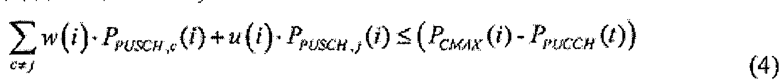
- Benutzergerät nach Anspruch 11, wobei der PUSCH der Zelle in dem aktuellen Subrahmen und der anderen Zelle, die Trägeraggregation mit der Zelle in dem aktuellen Subrahmen verarbeitet, einen PUSCH umfasst, der Aufwärtsstrecken-Steuersignalisierung trägt; und die Leistungsbestimmungseinheit (22) spezifisch ausgelegt ist zum
Bestimmen vierter Sendeleistung des PUSCH der Zelle in dem aktuellen Subrahmen und der anderen Zelle, die Trägeraggregation mit der Zelle in dem aktuellen Subrahmen verarbeitet, gemäß den Formeln (5) und (6), wobei:


- Benutzergerät nach Anspruch 10, wobei die durch die Überlappungsbestimmungseinheit (21) bestimmte Überlappung Folgendes umfasst: der PUSCH der Zelle in dem aktuellen Subrahmen oder ein PUCCH der Zelle in dem aktuellen Subrahmen oder ein PUSCH und/oder der PUCCH der Zelle in dem aktuellen Subrahmen ist mit einem PUSCH überlappt, der Aufwärtsstreckensignalisierung in der anderen Zelle in dem angrenzenden Subrahmen trägt, wobei sich die andere Zelle in Trägeraggregation mit der Zelle befindet.
- Benutzergerät nach Anspruch 15, wobei die Leistungsbestimmungseinheit (22) spezifisch ausgelegt ist zum
Bestimmen sechster Sendeleistung des PUSCH der Zelle in dem aktuellen Subrahmen und der anderen Zelle, die Trägeraggregation mit der Zelle in dem aktuellen Subrahmen verarbeitet, gemäß Formel (8), wobei:


- Benutzergerät nach Anspruch 15, wobei der PUSCH der Zelle in dem aktuellen Subrahmen und der anderen Zelle, die Trägeraggregation mit der Zelle in dem aktuellen Subrahmen verarbeitet, einen PUSCH umfasst, der Aufwärtsstrecken-Steuersignalisierung trägt; und die Leistungsbestimmungseinheit (22) spezifisch ausgelegt ist zum
Bestimmen achter Sendeleistung des PUSCH der Zelle in dem aktuellen Subrahmen und der anderen Zelle, die Trägeraggregation mit der Zelle in dem aktuellen Subrahmen verarbeitet, gemäß den Formeln (10) und (11) oder gemäß den Formeln (10) und (12), wobei:


Bestimmen neunter Sendeleistung des PUSCH der Zelle in dem aktuellen Subrahmen und der anderen Zelle, die Trägeraggregation mit der Zelle in dem aktuellen Subrahmen verarbeitet, gemäß Formel (13), wobei:

- Benutzergerät nach Anspruch 15, wobei der PUSCH der Zelle in dem aktuellen Subrahmen und der anderen Zelle, die Trägeraggregation mit der Zelle in dem aktuellen Subrahmen verarbeitet, einen PUSCH umfasst, der Aufwärtsstreckensignalisierung trägt; und die Leistungsbestimmungseinheit (22) spezifisch ausgelegt ist zum
Bestimmen zehnter Sendeleistung des PUSCH der Zelle in dem aktuellen Subrahmen und der anderen Zelle, die Trägeraggregation mit der Zelle in dem aktuellen Subrahmen verarbeitet, gemäß den Formeln (14) und (15) oder gemäß den Formeln (14) und (16), wobei:


Bestimmen elfter Sendeleistung des PUSCH der Zelle in dem aktuellen Subrahmen und der anderen Zelle, die Trägeraggregation mit der Zelle in dem aktuellen Subrahmen verarbeitet, gemäß Formel (17), wobei:
Applications Claiming Priority (2)
| Application Number | Priority Date | Filing Date | Title |
|---|---|---|---|
| CN201210004601.0A CN103200662B (zh) | 2012-01-09 | 2012-01-09 | 上行发送功率确定方法及用户设备 |
| PCT/CN2012/087885 WO2013104261A1 (zh) | 2012-01-09 | 2012-12-28 | 上行发送功率确定方法及用户设备 |
Publications (3)
| Publication Number | Publication Date |
|---|---|
| EP2804430A1 EP2804430A1 (de) | 2014-11-19 |
| EP2804430A4 EP2804430A4 (de) | 2014-11-26 |
| EP2804430B1 true EP2804430B1 (de) | 2017-04-19 |
Family
ID=48722979
Family Applications (1)
| Application Number | Title | Priority Date | Filing Date |
|---|---|---|---|
| EP12864798.9A Active EP2804430B1 (de) | 2012-01-09 | 2012-12-28 | Verfahren und benutzervorrichtung zur bestimmung einer uplink-sendeleistung |
Country Status (4)
| Country | Link |
|---|---|
| US (1) | US20140321392A1 (de) |
| EP (1) | EP2804430B1 (de) |
| CN (1) | CN103200662B (de) |
| WO (1) | WO2013104261A1 (de) |
Families Citing this family (9)
| Publication number | Priority date | Publication date | Assignee | Title |
|---|---|---|---|---|
| EP3131349B1 (de) | 2014-04-18 | 2020-08-26 | Huawei Technologies Co., Ltd. | Leistungskonfigurierungsverfahren, benutzerendgerät und basisstation |
| US10091736B2 (en) * | 2014-04-18 | 2018-10-02 | Kt Corporation | Method of controlling uplink signal transmission power and apparatus thereof |
| US10980045B2 (en) | 2014-10-02 | 2021-04-13 | Qualcomm Incorporated | Techniques for managing power on an uplink component carrier transmitted over a shared radio frequency spectrum band |
| CN106851809B (zh) * | 2015-12-03 | 2020-11-17 | 华为技术有限公司 | 确定功率的方法及用户设备 |
| WO2017113401A1 (zh) * | 2015-12-31 | 2017-07-06 | 华为技术有限公司 | 功率信息发送方法、终端设备和网络设备 |
| US10117188B2 (en) * | 2016-04-01 | 2018-10-30 | Motorola Mobility Llc | Method and apparatus for scheduling uplink transmissions with reduced latency |
| CN107734623A (zh) * | 2016-08-12 | 2018-02-23 | 夏普株式会社 | 用户设备、基站及其功率控制方法 |
| CN111093275A (zh) * | 2019-11-08 | 2020-05-01 | 中兴通讯股份有限公司 | 一种功率确定方法、装置、设备和存储介质 |
| US12278716B2 (en) * | 2020-05-14 | 2025-04-15 | Qualcomm Incorporated | SRS carrier switching for additional SRS |
Family Cites Families (9)
| Publication number | Priority date | Publication date | Assignee | Title |
|---|---|---|---|---|
| TWI388145B (zh) * | 2006-09-20 | 2013-03-01 | Interdigital Tech Corp | 用於壓縮模式間隔時隙的增強型專用頻道(e-dch)傳輸重疊檢測方法 |
| KR20150034775A (ko) * | 2009-02-09 | 2015-04-03 | 인터디지탈 패튼 홀딩스, 인크 | 다수의 반송파들을 이용하는 무선 송수신기 유닛에 대한 업링크 전력을 제어하는 장치 및 방법 |
| US9118468B2 (en) * | 2009-07-23 | 2015-08-25 | Qualcomm Incorporated | Asynchronous time division duplex operation in a wireless network |
| EP2484156B1 (de) * | 2009-10-02 | 2017-07-12 | InterDigital Patent Holdings, Inc. | Verfahren und vorrichtung zur steuerung der übertragungsleistung von übertragungen an mehr als einen komponententräger |
| JP2013520108A (ja) * | 2010-02-12 | 2013-05-30 | インターデイジタル パテント ホールディングス インコーポレイテッド | ダウンリンク協調コンポーネントキャリアを介してセルエッジユーザパフォーマンスを向上させるため、および無線リンク障害条件をシグナリングするための方法および装置 |
| KR101874276B1 (ko) * | 2010-04-01 | 2018-07-04 | 선 페이턴트 트러스트 | 물리적 랜덤 액세스 채널들에 대한 송신 전력 제어 |
| US20140003273A1 (en) * | 2011-04-04 | 2014-01-02 | Telefonaktiebolaget L M Ericsson (Publ) | Limiting Interference in a Heterogeneous Wireless Communication System |
| US9363780B2 (en) * | 2011-08-12 | 2016-06-07 | Intel Corporation | System and method of uplink power control in a wireless communication system |
| KR101306404B1 (ko) * | 2011-09-29 | 2013-09-09 | 엘지전자 주식회사 | 상향링크 전송 방법 및 이를 이용한 무선기기 |
-
2012
- 2012-01-09 CN CN201210004601.0A patent/CN103200662B/zh active Active
- 2012-12-28 EP EP12864798.9A patent/EP2804430B1/de active Active
- 2012-12-28 WO PCT/CN2012/087885 patent/WO2013104261A1/zh not_active Ceased
-
2014
- 2014-07-07 US US14/325,001 patent/US20140321392A1/en not_active Abandoned
Also Published As
| Publication number | Publication date |
|---|---|
| EP2804430A1 (de) | 2014-11-19 |
| CN103200662B (zh) | 2016-03-09 |
| WO2013104261A1 (zh) | 2013-07-18 |
| EP2804430A4 (de) | 2014-11-26 |
| US20140321392A1 (en) | 2014-10-30 |
| CN103200662A (zh) | 2013-07-10 |
Similar Documents
| Publication | Publication Date | Title |
|---|---|---|
| EP2804430B1 (de) | Verfahren und benutzervorrichtung zur bestimmung einer uplink-sendeleistung | |
| EP3731448B1 (de) | Leistungssteuerungsverfahren und endgerätevorrichtung | |
| EP3096551B1 (de) | Verfahren und benutzervorrichtung zum bestimmen einer uplink-sendeleistung | |
| US11856532B2 (en) | Data processing method, terminal, and base station | |
| EP3051871B1 (de) | Basisstation, mobilstation, drahtloskommunikationssystem und drahtloskommunikationsverfahren | |
| EP3726918B1 (de) | Signalübertragungsverfahren und -vorrichtung | |
| CA3066296C (en) | Data transmission method and terminal device | |
| EP3713291B1 (de) | Ressourcenzuweisungsanzeige- und -empfangsverfahren und -vorrichtungen | |
| US10251135B2 (en) | Method for controlling power of carrier signal, user equipment, and base station | |
| EP3376698A1 (de) | Übertragungsverfahren mit mehreren antennen unter co-zellen-netzwerk und basisstation | |
| EP4216460B1 (de) | Messverfahren, sendeverfahren und zugehörige vorrichtung | |
| US20190028188A1 (en) | Radio communication method and equipment | |
| CN115333598B (zh) | 信号放大器的增益控制方法、装置及网络侧设备 | |
| US20200186225A1 (en) | Method, network side device and terminal for indicating pilot precoding mode |
Legal Events
| Date | Code | Title | Description |
|---|---|---|---|
| PUAI | Public reference made under article 153(3) epc to a published international application that has entered the european phase |
Free format text: ORIGINAL CODE: 0009012 |
|
| 17P | Request for examination filed |
Effective date: 20140710 |
|
| AK | Designated contracting states |
Kind code of ref document: A1 Designated state(s): AL AT BE BG CH CY CZ DE DK EE ES FI FR GB GR HR HU IE IS IT LI LT LU LV MC MK MT NL NO PL PT RO RS SE SI SK SM TR |
|
| A4 | Supplementary search report drawn up and despatched |
Effective date: 20141027 |
|
| RIC1 | Information provided on ipc code assigned before grant |
Ipc: H04W 52/32 20090101ALI20141021BHEP Ipc: H04W 52/14 20090101AFI20141021BHEP Ipc: H04W 52/34 20090101ALI20141021BHEP |
|
| DAX | Request for extension of the european patent (deleted) | ||
| GRAP | Despatch of communication of intention to grant a patent |
Free format text: ORIGINAL CODE: EPIDOSNIGR1 |
|
| RIC1 | Information provided on ipc code assigned before grant |
Ipc: H04W 52/32 20090101ALI20161005BHEP Ipc: H04W 72/02 20090101ALI20161005BHEP Ipc: H04W 52/14 20090101AFI20161005BHEP Ipc: H04W 52/34 20090101ALI20161005BHEP |
|
| INTG | Intention to grant announced |
Effective date: 20161026 |
|
| RAP1 | Party data changed (applicant data changed or rights of an application transferred) |
Owner name: HUAWEI TECHNOLOGIES CO., LTD. |
|
| GRAS | Grant fee paid |
Free format text: ORIGINAL CODE: EPIDOSNIGR3 |
|
| GRAA | (expected) grant |
Free format text: ORIGINAL CODE: 0009210 |
|
| AK | Designated contracting states |
Kind code of ref document: B1 Designated state(s): AL AT BE BG CH CY CZ DE DK EE ES FI FR GB GR HR HU IE IS IT LI LT LU LV MC MK MT NL NO PL PT RO RS SE SI SK SM TR |
|
| REG | Reference to a national code |
Ref country code: GB Ref legal event code: FG4D |
|
| REG | Reference to a national code |
Ref country code: CH Ref legal event code: EP |
|
| REG | Reference to a national code |
Ref country code: AT Ref legal event code: REF Ref document number: 887013 Country of ref document: AT Kind code of ref document: T Effective date: 20170515 |
|
| REG | Reference to a national code |
Ref country code: IE Ref legal event code: FG4D |
|
| REG | Reference to a national code |
Ref country code: DE Ref legal event code: R096 Ref document number: 602012031486 Country of ref document: DE |
|
| REG | Reference to a national code |
Ref country code: NL Ref legal event code: MP Effective date: 20170419 |
|
| REG | Reference to a national code |
Ref country code: LT Ref legal event code: MG4D |
|
| REG | Reference to a national code |
Ref country code: AT Ref legal event code: MK05 Ref document number: 887013 Country of ref document: AT Kind code of ref document: T Effective date: 20170419 |
|
| PG25 | Lapsed in a contracting state [announced via postgrant information from national office to epo] |
Ref country code: NL Free format text: LAPSE BECAUSE OF FAILURE TO SUBMIT A TRANSLATION OF THE DESCRIPTION OR TO PAY THE FEE WITHIN THE PRESCRIBED TIME-LIMIT Effective date: 20170419 |
|
| PG25 | Lapsed in a contracting state [announced via postgrant information from national office to epo] |
Ref country code: LT Free format text: LAPSE BECAUSE OF FAILURE TO SUBMIT A TRANSLATION OF THE DESCRIPTION OR TO PAY THE FEE WITHIN THE PRESCRIBED TIME-LIMIT Effective date: 20170419 Ref country code: NO Free format text: LAPSE BECAUSE OF FAILURE TO SUBMIT A TRANSLATION OF THE DESCRIPTION OR TO PAY THE FEE WITHIN THE PRESCRIBED TIME-LIMIT Effective date: 20170719 Ref country code: AT Free format text: LAPSE BECAUSE OF FAILURE TO SUBMIT A TRANSLATION OF THE DESCRIPTION OR TO PAY THE FEE WITHIN THE PRESCRIBED TIME-LIMIT Effective date: 20170419 Ref country code: HR Free format text: LAPSE BECAUSE OF FAILURE TO SUBMIT A TRANSLATION OF THE DESCRIPTION OR TO PAY THE FEE WITHIN THE PRESCRIBED TIME-LIMIT Effective date: 20170419 Ref country code: FI Free format text: LAPSE BECAUSE OF FAILURE TO SUBMIT A TRANSLATION OF THE DESCRIPTION OR TO PAY THE FEE WITHIN THE PRESCRIBED TIME-LIMIT Effective date: 20170419 Ref country code: GR Free format text: LAPSE BECAUSE OF FAILURE TO SUBMIT A TRANSLATION OF THE DESCRIPTION OR TO PAY THE FEE WITHIN THE PRESCRIBED TIME-LIMIT Effective date: 20170720 Ref country code: ES Free format text: LAPSE BECAUSE OF FAILURE TO SUBMIT A TRANSLATION OF THE DESCRIPTION OR TO PAY THE FEE WITHIN THE PRESCRIBED TIME-LIMIT Effective date: 20170419 |
|
| PG25 | Lapsed in a contracting state [announced via postgrant information from national office to epo] |
Ref country code: LV Free format text: LAPSE BECAUSE OF FAILURE TO SUBMIT A TRANSLATION OF THE DESCRIPTION OR TO PAY THE FEE WITHIN THE PRESCRIBED TIME-LIMIT Effective date: 20170419 Ref country code: BG Free format text: LAPSE BECAUSE OF FAILURE TO SUBMIT A TRANSLATION OF THE DESCRIPTION OR TO PAY THE FEE WITHIN THE PRESCRIBED TIME-LIMIT Effective date: 20170719 Ref country code: PL Free format text: LAPSE BECAUSE OF FAILURE TO SUBMIT A TRANSLATION OF THE DESCRIPTION OR TO PAY THE FEE WITHIN THE PRESCRIBED TIME-LIMIT Effective date: 20170419 Ref country code: SE Free format text: LAPSE BECAUSE OF FAILURE TO SUBMIT A TRANSLATION OF THE DESCRIPTION OR TO PAY THE FEE WITHIN THE PRESCRIBED TIME-LIMIT Effective date: 20170419 Ref country code: RS Free format text: LAPSE BECAUSE OF FAILURE TO SUBMIT A TRANSLATION OF THE DESCRIPTION OR TO PAY THE FEE WITHIN THE PRESCRIBED TIME-LIMIT Effective date: 20170419 Ref country code: IS Free format text: LAPSE BECAUSE OF FAILURE TO SUBMIT A TRANSLATION OF THE DESCRIPTION OR TO PAY THE FEE WITHIN THE PRESCRIBED TIME-LIMIT Effective date: 20170819 |
|
| REG | Reference to a national code |
Ref country code: DE Ref legal event code: R097 Ref document number: 602012031486 Country of ref document: DE |
|
| PG25 | Lapsed in a contracting state [announced via postgrant information from national office to epo] |
Ref country code: EE Free format text: LAPSE BECAUSE OF FAILURE TO SUBMIT A TRANSLATION OF THE DESCRIPTION OR TO PAY THE FEE WITHIN THE PRESCRIBED TIME-LIMIT Effective date: 20170419 Ref country code: CZ Free format text: LAPSE BECAUSE OF FAILURE TO SUBMIT A TRANSLATION OF THE DESCRIPTION OR TO PAY THE FEE WITHIN THE PRESCRIBED TIME-LIMIT Effective date: 20170419 Ref country code: RO Free format text: LAPSE BECAUSE OF FAILURE TO SUBMIT A TRANSLATION OF THE DESCRIPTION OR TO PAY THE FEE WITHIN THE PRESCRIBED TIME-LIMIT Effective date: 20170419 Ref country code: DK Free format text: LAPSE BECAUSE OF FAILURE TO SUBMIT A TRANSLATION OF THE DESCRIPTION OR TO PAY THE FEE WITHIN THE PRESCRIBED TIME-LIMIT Effective date: 20170419 Ref country code: SK Free format text: LAPSE BECAUSE OF FAILURE TO SUBMIT A TRANSLATION OF THE DESCRIPTION OR TO PAY THE FEE WITHIN THE PRESCRIBED TIME-LIMIT Effective date: 20170419 |
|
| PLBE | No opposition filed within time limit |
Free format text: ORIGINAL CODE: 0009261 |
|
| STAA | Information on the status of an ep patent application or granted ep patent |
Free format text: STATUS: NO OPPOSITION FILED WITHIN TIME LIMIT |
|
| PG25 | Lapsed in a contracting state [announced via postgrant information from national office to epo] |
Ref country code: IT Free format text: LAPSE BECAUSE OF FAILURE TO SUBMIT A TRANSLATION OF THE DESCRIPTION OR TO PAY THE FEE WITHIN THE PRESCRIBED TIME-LIMIT Effective date: 20170419 Ref country code: SM Free format text: LAPSE BECAUSE OF FAILURE TO SUBMIT A TRANSLATION OF THE DESCRIPTION OR TO PAY THE FEE WITHIN THE PRESCRIBED TIME-LIMIT Effective date: 20170419 |
|
| 26N | No opposition filed |
Effective date: 20180122 |
|
| PG25 | Lapsed in a contracting state [announced via postgrant information from national office to epo] |
Ref country code: SI Free format text: LAPSE BECAUSE OF FAILURE TO SUBMIT A TRANSLATION OF THE DESCRIPTION OR TO PAY THE FEE WITHIN THE PRESCRIBED TIME-LIMIT Effective date: 20170419 |
|
| REG | Reference to a national code |
Ref country code: CH Ref legal event code: PL |
|
| REG | Reference to a national code |
Ref country code: IE Ref legal event code: MM4A |
|
| PG25 | Lapsed in a contracting state [announced via postgrant information from national office to epo] |
Ref country code: MT Free format text: LAPSE BECAUSE OF NON-PAYMENT OF DUE FEES Effective date: 20171228 Ref country code: LU Free format text: LAPSE BECAUSE OF NON-PAYMENT OF DUE FEES Effective date: 20171228 |
|
| REG | Reference to a national code |
Ref country code: FR Ref legal event code: ST Effective date: 20180831 |
|
| REG | Reference to a national code |
Ref country code: BE Ref legal event code: MM Effective date: 20171231 |
|
| PG25 | Lapsed in a contracting state [announced via postgrant information from national office to epo] |
Ref country code: IE Free format text: LAPSE BECAUSE OF NON-PAYMENT OF DUE FEES Effective date: 20171228 Ref country code: FR Free format text: LAPSE BECAUSE OF NON-PAYMENT OF DUE FEES Effective date: 20180102 |
|
| PG25 | Lapsed in a contracting state [announced via postgrant information from national office to epo] |
Ref country code: BE Free format text: LAPSE BECAUSE OF NON-PAYMENT OF DUE FEES Effective date: 20171231 Ref country code: CH Free format text: LAPSE BECAUSE OF NON-PAYMENT OF DUE FEES Effective date: 20171231 Ref country code: LI Free format text: LAPSE BECAUSE OF NON-PAYMENT OF DUE FEES Effective date: 20171231 |
|
| PG25 | Lapsed in a contracting state [announced via postgrant information from national office to epo] |
Ref country code: MC Free format text: LAPSE BECAUSE OF FAILURE TO SUBMIT A TRANSLATION OF THE DESCRIPTION OR TO PAY THE FEE WITHIN THE PRESCRIBED TIME-LIMIT Effective date: 20170419 Ref country code: HU Free format text: LAPSE BECAUSE OF FAILURE TO SUBMIT A TRANSLATION OF THE DESCRIPTION OR TO PAY THE FEE WITHIN THE PRESCRIBED TIME-LIMIT; INVALID AB INITIO Effective date: 20121228 |
|
| PG25 | Lapsed in a contracting state [announced via postgrant information from national office to epo] |
Ref country code: CY Free format text: LAPSE BECAUSE OF FAILURE TO SUBMIT A TRANSLATION OF THE DESCRIPTION OR TO PAY THE FEE WITHIN THE PRESCRIBED TIME-LIMIT Effective date: 20170419 |
|
| PG25 | Lapsed in a contracting state [announced via postgrant information from national office to epo] |
Ref country code: MK Free format text: LAPSE BECAUSE OF FAILURE TO SUBMIT A TRANSLATION OF THE DESCRIPTION OR TO PAY THE FEE WITHIN THE PRESCRIBED TIME-LIMIT Effective date: 20170419 |
|
| PG25 | Lapsed in a contracting state [announced via postgrant information from national office to epo] |
Ref country code: TR Free format text: LAPSE BECAUSE OF FAILURE TO SUBMIT A TRANSLATION OF THE DESCRIPTION OR TO PAY THE FEE WITHIN THE PRESCRIBED TIME-LIMIT Effective date: 20170419 |
|
| PG25 | Lapsed in a contracting state [announced via postgrant information from national office to epo] |
Ref country code: PT Free format text: LAPSE BECAUSE OF FAILURE TO SUBMIT A TRANSLATION OF THE DESCRIPTION OR TO PAY THE FEE WITHIN THE PRESCRIBED TIME-LIMIT Effective date: 20170419 |
|
| PG25 | Lapsed in a contracting state [announced via postgrant information from national office to epo] |
Ref country code: AL Free format text: LAPSE BECAUSE OF FAILURE TO SUBMIT A TRANSLATION OF THE DESCRIPTION OR TO PAY THE FEE WITHIN THE PRESCRIBED TIME-LIMIT Effective date: 20170419 |
|
| PGFP | Annual fee paid to national office [announced via postgrant information from national office to epo] |
Ref country code: DE Payment date: 20251104 Year of fee payment: 14 |
|
| PGFP | Annual fee paid to national office [announced via postgrant information from national office to epo] |
Ref country code: GB Payment date: 20251114 Year of fee payment: 14 |