EP2804337B1 - PLS Header Coding for Efficient Signaling of Modulation and Coding Schemes for Broadband Satellite Communications Systems - Google Patents
PLS Header Coding for Efficient Signaling of Modulation and Coding Schemes for Broadband Satellite Communications Systems Download PDFInfo
- Publication number
- EP2804337B1 EP2804337B1 EP14168480.3A EP14168480A EP2804337B1 EP 2804337 B1 EP2804337 B1 EP 2804337B1 EP 14168480 A EP14168480 A EP 14168480A EP 2804337 B1 EP2804337 B1 EP 2804337B1
- Authority
- EP
- European Patent Office
- Prior art keywords
- modulation
- mode
- indicator field
- coding
- mode indicator
- Prior art date
- Legal status (The legal status is an assumption and is not a legal conclusion. Google has not performed a legal analysis and makes no representation as to the accuracy of the status listed.)
- Active
Links
Images


Classifications
-
- H—ELECTRICITY
- H04—ELECTRIC COMMUNICATION TECHNIQUE
- H04W—WIRELESS COMMUNICATION NETWORKS
- H04W72/00—Local resource management
- H04W72/04—Wireless resource allocation
-
- H—ELECTRICITY
- H04—ELECTRIC COMMUNICATION TECHNIQUE
- H04L—TRANSMISSION OF DIGITAL INFORMATION, e.g. TELEGRAPHIC COMMUNICATION
- H04L1/00—Arrangements for detecting or preventing errors in the information received
- H04L1/0001—Systems modifying transmission characteristics according to link quality, e.g. power backoff
- H04L1/0023—Systems modifying transmission characteristics according to link quality, e.g. power backoff characterised by the signalling
- H04L1/0028—Formatting
- H04L1/0029—Reduction of the amount of signalling, e.g. retention of useful signalling or differential signalling
-
- H—ELECTRICITY
- H04—ELECTRIC COMMUNICATION TECHNIQUE
- H04L—TRANSMISSION OF DIGITAL INFORMATION, e.g. TELEGRAPHIC COMMUNICATION
- H04L45/00—Routing or path finding of packets in data switching networks
- H04L45/74—Address processing for routing
Definitions
- DVB-S2 is a digital satellite transmission system standard covering framing structure, channel coding and modulation systems, designed for broadcast services (for standard and high definition television), interactive services (e.g., Internet access for consumer applications), and other broadband satellite applications.
- DVB-S2 represents a flexible standard, covering a variety of data and multimedia services delivered over satellite communications systems.
- the DVB-S2 standard covers various technological features, such as a flexible input stream adapter (suitable for operation with single and multiple input streams of various formats), a robust forward error correction coding (FEC) system based on low-density parity check (LDPC) codes concatenated with Bose Chaudhuri Hocquenghem (BCH) codes, a wide range of code rates (from 1/4 up to 9/10), four signal constellations (ranging in spectrum efficiency from 2 bit/s/Hz to 5 bit/s/Hz), and adaptive coding and modulation (ACM) functionality (optimizing channel coding and modulation on a frame-by-frame basis).
- FEC forward error correction coding
- LDPC low-density parity check
- BCH Bose Chaudhuri Hocquenghem
- ACM adaptive coding and modulation
- the DVB-S2 standard Since its inception, the DVB-S2 standard has been adopted globally as a predominant standard for broadcast, interactive and other broadband applications and services over satellite communications networks.
- the current modulation and coding schemes e.g., the modulation and coding schemes of the DVB-S2 standard
- SNR signal-to-noise ratio
- such current modulation and coding schemes are unable to support the operational requirements for higher end terminals (e.g., above 15.5 dB).
- the modulation and coding schemes of the current DVB-S2 standard lack sufficient granularity to meet the requirements of terminals in the growing field of broadcast, interactive and other broadband applications and services over satellite communications networks.
- the associated signaling provided to the receiver for proper decoding (e.g., the physical layer header signaling) must similarly be expanded to support identification of the expanded modulation and coding.
- One method for expanding the physical layer header signaling to support expanded modulation and coding scheme sets would simply be to increase the header size to directly support the expanded header signaling.
- Bandwidth resources and system efficiencies are already being pushed to the limits in support of new wideband systems and higher data rate applications.
- the addition of additional signaling bits in the physical layer headers would thus create the undesirable effect of utilizing already scarce bandwidth for additional signaling overhead.
- An alternative method has been proposed in technical literature, whereby two different scramblers could be employed to provide the signaling of an additional bit.
- one scrambler would be used to signify an additional bit (e.g., the most significant bit) as being zero (0), and the other scrambler would be used to signify the bit as being one (1).
- This approach suffers from disadvantages associated with cross-correlation of the two scramblers, which could never be zero, and thus, there will be more degradation from the original Reed-Muller code in performance.
- 3GPP draft document " Transport Block Size and MCS Signaling for E-UTRA" 3GPP RAN WG1, R1-074591, 29/10/2007 discloses methods to signal MCS to E-UTRA.
- the UE blindly detects the number of CCE used for PDCCH transmission, the number of CCE used for PDCCH transmission being related to the selected set of MCS.
- WO001030 “Signalling transmission using phase rotation techniques in a digital communications system”, discloses a way to signal a selected modulation (and coding) scheme without generating any overhead. This is achieved by rotating a modulation constellation of the signal by a specific phase determined according to the selected modulation (and coding) scheme. All the symbols of a preamble can be rotated for instance.
- the present invention advantageously addresses the foregoing requirements and needs, as well as others, by providing a system and methods for an improved coding approach, providing efficient header signaling in broadband satellite communications networks in support of expanded modulation and coding schemes that facilitate an expansion of the operational ranges of user terminals within such networks and finer granularity within such operational ranges.
- Independent claims 1 and 5 define methods to transmit and receive a mode indicator field according to the invention respectively.
- Corresponding apparatus are defined in independent claims 9 and 13 respectively.
- Preferred embodiments are defined in the dependent claims.
- a system and methods for an improved coding approach, providing efficient header signaling in broadband satellite communications networks in support of expanded modulation and coding schemes that facilitate an expansion of the operational ranges of user terminals within such networks and finer granularity within such operational ranges, is described.
- numerous specific details are set forth in order to provide a thorough understanding of the invention. It is apparent, however, that the invention may be practiced without these specific details or with an equivalent arrangement. In other instances, well known structures and devices are shown in block diagram form in order to avoid unnecessarily obscuring the invention.
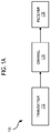
- FIG. 1A illustrates a communications system capable of employing modulation and coding protocols, in accordance with example embodiments of the present invention.
- a broadband communications system 110 includes one or more transmitters 112 (of which one is shown) that generate signal waveforms for transmission to one or more receivers 116 (of which one is shown).
- the signal waveforms are transmitted across a communications channel 114, which (for example) may comprise a channel of a terrestrial, wireless terrestrial or satellite communications system.
- the transmitter 112 has a signal source that produces a discrete set of data signals, where each of the data signals is transmitted over a corresponding signal waveform.
- the discrete set of data signals may first be encoded (e.g., via a forward error correction (FEC) code) to combat noise and other issues associated with the channel 114. Once encoded, the encoded signals may then be modulated onto a carrier for transmission over the channel 114. The signal waveforms are attenuated, or otherwise altered, by communications channel 114.
- FEC forward error correction
- FEC is required in terrestrial and satellite systems to provide high quality communication over a radio frequency (RF) propagation channel, which induces signal waveform and spectrum distortions, including signal attenuation (freespace propagation loss), multi-path induced fading and adjacent channel interference.
- RF radio frequency
- These impairments drive the design of the radio transmission and receiver equipment; example design objectives include selecting modulation formats, error control schemes, demodulation and decoding techniques and hardware components that together provide an efficient balance between system performance and implementation complexity. Differences in propagation channel characteristics, such as between terrestrial and satellite communication channels, naturally result in significantly different system designs.
- existing communications systems continue to evolve in order to satisfy increased system requirements for new higher rate or higher fidelity communication services.
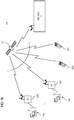
- FIG. 1B illustrates a satellite communications system capable of employing modulation and coding protocols, in accordance with example embodiments of the present invention.
- satellite communications system 120 includes a satellite 121 that supports communication among multiple satellite terminals (STs) 123a-123n, user terminals (UTs) 127a-127n, and a hub 127.
- the HUB 127 may assume the role of a Network Operations Center (NOC), which controls the access of the STs 123a-123n and UTs 127a-127n to the system 120, and also provides element management functions and control of the address resolution and resource management functionality.
- NOC Network Operations Center
- the Satellite communications system 120 may operate as a traditional bent-pipe system, where the satellite essentially operates as a repeater. Alternatively, the system 120 may employ a switching or processing satellite supporting mesh communications (point-to-point communications directly between a pair of the STs 123a-123n and UTs 127a-127n).
- the satellite operates as a repeater or bent pipe, and communications between the STs 123a-123n and UTs 127a-127n are transmitted over a double-hop path.
- the communication is transmitted, via the satellite, from the ST 123a to the HUB 127.
- the HUB 127 decodes the communication and determines the destination as ST 123n.
- the HUB 127 then appropriately addresses and repackages the communication, encodes and modulates it, and transmits the communication over the second hop, via the satellite, to the destination ST 123n.
- the satellite of such a system acts as a bent pipe or repeater, transmitting communications between the HUB 127 and the STs/UTs.
- the system may support direct unicast (point-to-point) communications and multicast communications among the STs 123a-123n and UTs 127a-127n.
- the satellite 121 decodes the received signal and determines the destination ST(s)/UT(s) (as the hub 127 would in a bent-pipe system). The satellite 121 then addresses the data accordingly, encodes and modulates it, and transmits the modulated signal, over the channel 114, to the destination ST(s)/UT(s).
- the STs 123a-123n may each provide connectivity to one or more respective hosts (e.g., hosts 125a-125n, respectively).
- data signals destined for high S/N terminals may be multiplexed with data signals destined for lower S/N terminals (e.g., any of the UTs 127a-127n), on the same channel 114 (on a frame-by-frame basis).
- high S/N terminals e.g., any of the STs 125a-125n
- lower S/N terminals e.g., any of the UTs 127a-127n
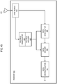
- FIG. 2A illustrates a block diagram of an example transmitter configured to operate in the systems of FIGs. 1A and 1B , in accordance with example embodiments of the present invention.
- the transmitter 210 is equipped with a data encapsulation module 211 that accepts the original application layer source data and performs the upper layer encapsulation to from the baseband frames.
- the encoder e.g., an FEC encoder
- the encoded signal is fed to the modulator 215, which maps the encoded messages to signal waveforms, based in part on modulation signal constellations.
- the data encapsulation module 211 performs the upper layer encapsulation to generate the baseband frames based on the source data bits, and then the encoder 213 and modulator 215 collectively perform the modulation and coding of the baseband frames and the generation of the physical layer frames, in accordance with the example embodiments of the present invention.
- the physical layer frames are then transmitted (as signal waveforms), via the transmit antenna 217, over the communication channel 114 to the satellite 121.
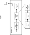
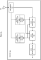
- FIG. 2B illustrates a block diagram of an example receiver configured to operate in the systems of FIGs. 1A and 1B , in accordance with example embodiments of the present invention.
- the receiver 220 comprises receive antenna 229, sync module 227 demodulator 225, decoder 223 and de-encapsulation module 221.
- the receive antenna 229 receives the signal waveform transmitted over the channel 114 from the satellite 121.
- the sync module 227 detects the unique word, performs synchronization and determines the modcod and other PLS signaling of the PL Header.
- the demodulator 225 demodulates the received signal waveforms, based in part on the signal constellation employed for the modulation, to obtain the encoded signals.
- the decoder 223 then decodes the demodulated bit sequence to generate the encapsulated message data, and the de-encapsulation module 221 de-encapsulates the message data to regenerate the original source data.
- DVB-S2 As mentioned above, as one example embodiment for broadcast and broadband communications services over satellite networks, the DVB-S2 standard has been adopted globally as a predominant standard for broadcast, interactive and other broadband services and applications.
- the framing structure, channel coding and modulation systems of the DVB-S2 standard are described in the European Telecommunications Standards Institute (ETSI) publication, ETSI EN 302 307 V1.3.1.
- DVB-S2 represents a flexible standard, covering a variety of data and multimedia services delivered over satellite communications systems.
- GSE Generic Stream Encapsulation
- GSE Generic Stream Encapsulation
- DVB-S2 Generic Stream Encapsulation
- DVB-S2 Generic Stream Encapsulation
- application data in the form of packet data units (PDUs) are first encapsulated within the baseband frames of the communications network (e.g., DVB-S2 baseband packets in a satellite communications system).
- PDUs packet data units
- the DVB-S2 standard was designed to facilitate robust synchronization and signaling at the physical layer, and synchronization and detection of the modulation and coding parameters by a receiver before demodulation and FEC decoding.
- baseband frames are first encoded to form an output stream of FEC frames.
- the baseband frames are encoded by the FEC encoder 213, which comprises a t-error BCH outer coding via the BCH encoder 213a, an LDPC inner coding via the LDPC encoder 213b, and bit interleaving via the bit interleaver 213c.
- the interleaver 213c reorders the encoded sequence of symbols or bits from the LDPC encoder 213b in a predetermined manner.
- Each FEC frame is then modulated based on one of various options specified in the standard for modulation of the data payload (e.g., QPSK, 8PSK, 16APSK, or 32APSK). For example, each FEC frame is serial-to-parallel converted, and each resulting parallel sequence is mapped based on a signal constellation, generating an (I, Q) sequence of variable length depending on the selected modulation efficiency ( ⁇ MOD bits/Hz).
- the resulting output sequence is referred to as a complex FEC frame or XFEC frame, composed of 64,800/ ⁇ MOD (normal XFEC frame) modulation symbols for a normal XFEC frame, or 16,200/ ⁇ MOD (short XFEC frame) modulation symbols for a short XFEC frame.
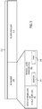
- FIG. 3 illustrates the frame format of a physical layer frame in accordance with the prior art DVB-S2 framing structure, channel coding and modulation systems standard.
- the DVB-S2 physical layer framing comprises the structuring of the baseband frames (resulting from the upper layer encapsulation of user or application data) as a regular sequence of periodic physical layer frames (PL Frames) 311. Every PL Frame is composed of a physical layer data payload (PL Payload) 313 and a physical layer header (PL Header) 215.
- the payload comprises the modulation symbols resulting from the encoding and modulation of the source data bits, generated by encoding and modulating the source data bits according to the selected modulation and coding scheme, as described above.
- the PL Payload 313 corresponds to a code block of a concatenated LDPC/BCH FEC.
- the PL Header 315 which is intended for receiver synchronization and physical layer signaling, contains synchronization and signaling information (e.g., Start of Frame or UW field, type of modulation and FEC rate, frame length, presence/absence of pilot symbols).
- the PL Header for example, comprises one slot of 90 symbols, and the PL Payload comprises an integer multiple of 90 symbols (excluding pilot symbols).
- BPSK binary phase shift keying
- the PL Header is composed of a Start of Frame (SOF) field (also referred to herein as the Unique Word or UW) 321 (e.g., comprising 26 symbols).
- SOF Start of Frame
- UW Unique Word
- the UW is uniform from frame to frame, and is inserted generally as a synchronization word for frame detection.
- the UW is used as a reference for detection of a burst or frame, and as a timing and frequency reference for decoding the header and payload portion of the frame.
- the UW field is followed by a Physical Layer Signaling (PLS) field 323 (e.g., comprising 64 symbols).
- PLS Physical Layer Signaling
- the PLS field reflects seven signaling bits representing a mode indicator to identify the modulation and coding scheme applied to the PL data payload.
- the PLS field is encoded via a very low-rate block code (suitable for soft-decision correlation decoding, such as Fast Hadarmad Transform decoding), and a minimized number of signaling bits to reduce decoding complexity and global efficiency loss.
- the PLS field is always encoded in this fashion, because it is the first entity to be decoded by the receiver and provides the requisite information (e.g., modcod and type information, discussed below) necessary for enabling the receiver to decode the PL Data Payload, and thus the header must be decodable under worst-case link conditions.
- the PLS field is bi-orthogonally coded via a non-systematic binary code of length 64 and dimension seven (64, 7), such as a first order Reed-Muller code under permutation.
- the PLS field is thereby encoded into 64 bits to form a bi-orthogonal signal set, which performs extremely well in noisy channels.
- the seven signaling bits of the PLS field comprise two fields, a 5-bit modulation and coding or "modcod" field 331, and a 2-bit type field 333.
- the modcod field identifies the modulation and coding applied to the data payload (e.g., the modulation and coding applied to convert the baseband frames into the encoded and modulated XFEC frames - the XFEC frame modulation and FEC code rate).
- the type field identifies the FEC frame length (either 64,800 bits or 16,200 bits) and indicates the presence or absence of pilot symbol blocks.
- the modcod field comprises 5-bits identifying the modulation and code rate applied to the PL payload data.
- Each unique combination of the 5-bit modcod field reflects one of 28 possible modulation/code-rate schemes (plus 3 reserved modcod values and one value reflecting a dummy PL Frame).
- the 32 values for the 5-bit modcod field of the DVB-S2 standard reflect the following modcod schemes: MODCOD Value Mode (Modulation:Rate) MODCOD Value Mode (Modulation: Rate) 1 QPSK:1/4 17 8PSK:9/10 2 QPSK:1/3 18 16APSK:2/3 3 QPSK:2/5 19 16APSK:3/4 4 QPSK:1/2 20 16APSK:4/5 5 QPSK:3/5 21 16APSK:5/6 6 QPSK:2/3 22 16APSK:8/9 7 QPSK:3/4 23 16APSK:9/10 8 QPSK:4/5 24 32APSK:3/4 9 QPSK:5/6 25 32APSK:4/5 10 QPSK:8/9 26 32APSK:5/6 11 QPSK:9/10 27 32APSK:8/9 12
- an additional set of 32 modulation/code-rate schemes may be signaled or identified using the same 7-bit signaling, without including any additional signaling bits in the PLS field or in the PL Header overall (which otherwise would consume additional bandwidth/overhead).
- an additional "virtual" flag bit e.g., a virtual most significant bit (MSB), referred to here as a virtual bit, because an additional bit need not actually be transmitted to communicate the bit value
- MSB virtual most significant bit
- the 7-bit PLS field would be ⁇ /2 BPSK modulated in the same manner as specified by the DVB-S2 standard.
- the 7-bit PLS field would be modulated 90 degrees (90°) out of phase as compared to the normal ⁇ /2 BPSK modulation (e.g., modulated at a 90 degree lag or advance. All other aspects of the transmission would be the same.
- the one-bit virtual flag information is embedded in the phase of the Reed-Mueller code block.
- the 5-bit modcod field would reflect or identify the 32 modcod schemes of the DVB-S2 standard, while, under the out-of-phase modulation, the 5-bit modcod field would reflect or identify an additional 32 modulation/code-rate schemes.
- one or both of the 2 bits of the type field may additionally be used for the modcod field, increasing the number of additional modulation/code-rate schemes up to 64 or 128 (depending on whether just one or both of the type bits are used for additional modcod field bits).
- the SOF or UW pattern would still be transmitted without any phase shift.
- the foregoing example specifies a modulation phase shift of 90 degrees, it is contemplated that alternative methods of altering the modulation of the PLS filed may be employed to signal different states of such a "virtual" flag or indicator bit.
- FIG. 4A illustrates a block diagram of an example receiver configured to operate in the systems of FIGs. 1A and 1B , in accordance with example embodiments of the present invention.
- the PLS field demodulators/decoders and data demodulator and decoder are broken out separately. As would be recognized, however, these components may be implemented according to various different hardware/software/firmware configurations.
- the receiver 420 comprises the antenna 429 and sync module 427.
- the sync module 427 establishes/maintains synchronization based on the SOF or UW field. Based on the synchronization, the PLS field information is fed to two different PLS field demodulator/decoder pairs 433a/435a and 433b/433a.
- the decoders comprise two Reed-Muller decoders operating in parallel. Based on the synchronization established by the SOF, one decoder operates in-phase with the "normal" PLS field modulation, while the other decoder operates out-of-phase by 90 degrees from the "normal" PLS field modulation. Each decoder picks a codeword out of the 128 possible Reed-Muller codewords of 64 bits that best matches the received signal samples. The receiver then picks the better correlation of the two to determine the intended value of the "virtual" flag or indicator bit.
- the decoder adds a zero "0" as a new most significant bit of the 7-bit PLS field - in which case the 5-bit modcod field value remains as transmitted (e.g., the modcod field remains as the transmitted value from 0-31 identifying a one of the 32 modes of the DVB-S2 standard).
- the decoder adds a one "1" as a new most significant bit of the 7-bit PLS field - in which case the transmitted 5-bit modcod field value is effectively increased by 32 (e.g., the modcod field takes on a value of the transmitted value + 32, taking on a value from 32-63 identifying a one of 32 additional modes or modulation/code-rate schemes).
- the type field bits e.g., the short/long code indicator bit
- 6 bits are available for modcod identifiers - increasing the additional mdocod schemes to 64.
- modcod scheme identifiers e.g., an additional 128 modcod schemes.
- the appropriate information is then communicated to the data demodulator 425 and decoder 423 for proper demodulation and decoding of the PL data payload, in accordance with the identified modcod scheme.
- the data de-encapsulation module 421 then de-encapsulates the data to generate the source bit stream.
- FIG. 4B illustrates a block diagram of a further example receiver configured to operate in the systems of FIGs. 1A and 1B , in accordance with example embodiments of the present invention.
- the PLS field demodulator/decoder and data demodulator and decoder are broken out separately. As would be recognized, however, these components may be implemented according to various different hardware/software/firmware configurations.
- the receiver 440 comprises only a single PLS field demodulator/decoder pair 443 and 445.
- the receiver 440 operates in the same manner as the receiver 420, except that the PLS field demodulator/decoder of the receiver 440 must operate at least at twice the speed of each the PLS field demodulator decoder pairs of the receiver 420.
- the PLS field demodulator/decoder 443/445 operates on each received PLS field in one phase at a time (e.g., first at the phase of the "normal" PLS field modulation, and then at a phase orthogonal to - out of phase by 90 degrees with respect to - the "normal" phase.
- the demodulator/decoder 443/445 determines the best correlation of the 2 phases and adds the appropriate 8 th bit (MSB) to the 7-bit PLS field.
- MSB 8 th bit
- FIG. 5 illustrates a flow chart of an example process for encoding and modulating a source data sequence of information bits, in accordance with example embodiments of the present invention.
- the process begins with the receipt of the source data frames.
- the source data frames are encoded and modulated in accordance with a desired modulation and coding (modcod) scheme selected from a set of predetermined modcod schemes to generate the PL data payload.
- modcod modulation and coding
- the modcod and type fields are set according to the selected modcod scheme applied to the data (the modcod and type fields make up the PLS field of the PL Header), and the resulting PLS field bits are encoded.
- a synchronization (sync) header (e.g., UW or SOF field) is appended to the PLS field to form the PL Header.
- the modcod field value corresponds to a modcod scheme of a first set of modcod schemes (e.g., in the case of DVB-S2, the modcod field is of a value from 0-31 signifying one of the DVB-S2 modcod schemes), then the PLS field is modulated at the "normal" phase.
- the PLS field is modulated at a phase shifted by 90 degrees from that of the "normal" PLS field modulation.
- the PL Header is appended to the PL data payload to form the PL Frame.
- FIG. 6 illustrates a flow chart of an example process for demodulating and decoding a received data signal transmission, in accordance with example embodiments of the present invention.
- the process may be performed by one or more modules of a receiver (e.g., the receiver 420 of FIG. 4A or the receiver 440 of FIG. 4B ).
- the process starts at step 611, where the data signals transmitted over the satellite channel are received by the receiver 420/440.
- the sync module 427 detects the unique word and acquires synchronization.
- the PLS field demodulator/decoder determines the phase of the modulation applied to the PLS field at the transmitter.
- the data demodulator 425 demodulates the data payload signal, and the data decoder 423 decodes the demodulated data payload signal based on the determined modulation and coding schemes.
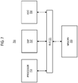
- FIG. 7 illustrates a block diagram of a chip set that can be utilized in implementing communications system protocols, according to example embodiments of the present invention.
- chip set 700 includes, for instance, processor and memory components described with respect to FIG. 5 incorporated in one or more physical packages.
- a physical package includes an arrangement of one or more materials, components, and/or wires on a structural assembly (e.g., a baseboard) to provide one or more characteristics such as physical strength, conservation of size, and/or limitation of electrical interaction.
- the chip set 700 includes a communication mechanism such as a bus 701 for passing information among the components of the chip set.
- a processor 703 has connectivity to the bus 701 to execute instructions and process information stored in, for example, a memory 705.
- the processor 703 includes one or more processing cores with each core configured to perform independently.
- a multi-core processor enables multiprocessing within a single physical package. Examples of a multi-core processor include two, four, eight, or greater numbers of processing cores.
- the processor 503 includes one or more microprocessors configured in tandem via the bus 701 to enable independent execution of instructions, pipelining, and multithreading.
- the processor 703 may also be accompanied with one or more specialized components to perform certain processing functions and tasks such as one or more digital signal processors (DSP) 707, and/or one or more application-specific integrated circuits (ASIC) 709.
- DSP 707 typically is configured to process real-world signals (e.g., sound) in real time independently of the processor 703.
- ASIC 709 can be configured to performed specialized functions not easily performed by a general purposed processor.
- Other specialized components to aid in performing the inventive functions described herein include one or more field programmable gate arrays (FPGA) (not shown), one or more controllers (not shown), or one or more other special-purpose computer chips.
- FPGA field programmable gate arrays
- the processor 703 and accompanying components have connectivity to the memory 705 via the bus 701.
- the memory 705 may comprise various forms of computer-readable media, e.g., including both dynamic memory (e.g., RAM) and static memory (e.g., ROM) for storing executable instructions that, when executed by the processor 703 and/or the DSP 707 and/or the ASIC 709, perform the process of example embodiments as described herein.
- the memory 705 also stores the data associated with or generated by the execution of the process.
- Non-volatile media include, for example, read only memory (ROM), included within memory 705.
- Volatile media for example, may include dynamic random access memory (RAM), included within memory 705.
- Transmission media may include conductive wiring, fiber optics, or other physical transmission media, including the media that comprise bus 701.
- Transmission media can also take the form of wireless data signals, such as radio frequency (RF) and infrared (IR) data communications.
- RF radio frequency
- IR infrared
- Common forms of computer-readable media include, for example, magnetic storage media (e.g., magnetic hard disks or any other magnetic storage medium), solid state or semiconductor storage media (e.g., RAM, PROM, EPROM, FLASH EPROM, a data storage device that uses integrated circuit assemblies as memory to store data persistently, or any other storage memory chip or module), optical storage media (e.g., CD ROM, CDRW, DVD, or any other optical storage medium), a or any other medium for storing data from which a computer or processor can read.
- magnetic storage media e.g., magnetic hard disks or any other magnetic storage medium
- solid state or semiconductor storage media e.g., RAM, PROM, EPROM, FLASH EPROM, a data storage device that uses integrated circuit assemblies as memory to store data persistently, or any other storage memory chip or module
- the instructions for carrying out at least part of the present invention may initially be borne on a magnetic disk of a remote computer.
- the remote computer loads the instructions into main memory and sends the instructions over a telephone line using a modem.
- a modem of a local computer system receives the data on the telephone line and uses an infrared transmitter to convert the data to an infrared signal and transmit the infrared signal to a portable computing device, such as a personal digital assistance (PDA) and a laptop.
- PDA personal digital assistance
- An infrared detector on the portable computing device receives the information and instructions borne by the infrared signal and places the data on a bus.
- the bus conveys the data to main memory, from which a processor retrieves and executes the instructions.
- the instructions received by main memory may optionally be stored on storage device either before or after execution by processor.
- a module or component may be composed of software component(s), which are stored in a memory or other computer-readable storage medium, and executed by one or more processors or CPUs of the respective devices.
- a module may alternatively be composed of hardware component(s) or firmware component(s), or a combination of hardware, firmware and/or software components.
- example embodiments of the present invention may provide for various implementations (e.g., including hardware, firmware and/or software components), and, unless stated otherwise, all functions are performed by a CPU or a processor executing computer executable program code stored in a non-transitory memory or computer-readable storage medium, the various components can be implemented in different configurations of hardware, firmware, software, and/or a combination thereof. Except as otherwise disclosed herein, the various components shown in outline or in block form in the figures are individually well known and their internal construction and operation are not critical either to the making or using of this invention or to a description of the best mode thereof.
Landscapes
- Engineering & Computer Science (AREA)
- Computer Networks & Wireless Communication (AREA)
- Signal Processing (AREA)
- Quality & Reliability (AREA)
- Digital Transmission Methods That Use Modulated Carrier Waves (AREA)
- Radio Relay Systems (AREA)
Applications Claiming Priority (1)
| Application Number | Priority Date | Filing Date | Title |
|---|---|---|---|
| US13/896,275 US8964896B2 (en) | 2013-05-16 | 2013-05-16 | PLS header coding for efficient signaling of modulation and coding schemes for broadband satellite communications systems |
Publications (2)
| Publication Number | Publication Date |
|---|---|
| EP2804337A1 EP2804337A1 (en) | 2014-11-19 |
| EP2804337B1 true EP2804337B1 (en) | 2018-02-21 |
Family
ID=50771420
Family Applications (1)
| Application Number | Title | Priority Date | Filing Date |
|---|---|---|---|
| EP14168480.3A Active EP2804337B1 (en) | 2013-05-16 | 2014-05-15 | PLS Header Coding for Efficient Signaling of Modulation and Coding Schemes for Broadband Satellite Communications Systems |
Country Status (5)
| Country | Link |
|---|---|
| US (1) | US8964896B2 (enExample) |
| EP (1) | EP2804337B1 (enExample) |
| BR (1) | BR102014011894B1 (enExample) |
| IN (1) | IN2014MU01654A (enExample) |
| NO (1) | NO3022800T3 (enExample) |
Families Citing this family (20)
| Publication number | Priority date | Publication date | Assignee | Title |
|---|---|---|---|---|
| US9647799B2 (en) * | 2012-10-16 | 2017-05-09 | Inphi Corporation | FEC coding identification |
| KR102002559B1 (ko) | 2013-07-05 | 2019-07-22 | 삼성전자주식회사 | 송신 장치 및 그의 신호 처리 방법 |
| KR20150005853A (ko) * | 2013-07-05 | 2015-01-15 | 삼성전자주식회사 | 송신 장치 및 그의 신호 처리 방법 |
| KR101776275B1 (ko) | 2014-02-19 | 2017-09-07 | 삼성전자주식회사 | 송신 장치 및 그의 인터리빙 방법 |
| US9602137B2 (en) * | 2014-02-19 | 2017-03-21 | Samsung Electronics Co., Ltd. | Transmitting apparatus and interleaving method thereof |
| US10021695B2 (en) * | 2015-04-14 | 2018-07-10 | Qualcomm Incorporated | Apparatus and method for generating and transmitting data frames |
| US9692453B2 (en) | 2015-05-19 | 2017-06-27 | Samsung Electronics Co., Ltd. | Transmitting apparatus and interleaving method thereof |
| US9595978B2 (en) | 2015-05-19 | 2017-03-14 | Samsung Electronics Co., Ltd. | Transmitting apparatus and interleaving method thereof |
| US9680505B2 (en) | 2015-05-19 | 2017-06-13 | Samsung Electronics Co., Ltd. | Transmitting apparatus and interleaving method thereof |
| US9634692B2 (en) | 2015-05-19 | 2017-04-25 | Samsung Electronics Co., Ltd. | Transmitting apparatus and interleaving method thereof |
| FR3047624B1 (fr) * | 2016-02-05 | 2019-05-10 | Thales | Procede de bord de routage transparent de paquets de donnees a tres haut debit dans un systeme de telecommunications spatial utilisant un reseau d'au moins satellite(s) regeneratif(s) |
| DE102016213764B4 (de) * | 2016-07-27 | 2018-02-22 | Deutsches Zentrum für Luft- und Raumfahrt e.V. | Verfahren zum Übertragen eines binären Datensignals über einen optischen Feeder-Link zu oder von einem Satelliten |
| US10727977B2 (en) * | 2016-12-30 | 2020-07-28 | Hughes Network Systems, Llc | System and method for improving forward error correction efficiency |
| US10339623B2 (en) | 2017-08-11 | 2019-07-02 | Harris Corporation | Phase rotation watermarking for phase modulation |
| US10785086B1 (en) | 2019-07-10 | 2020-09-22 | Eagle Technology, Llc | Detection of phase rotation modulation |
| US11223372B2 (en) | 2019-11-27 | 2022-01-11 | Hughes Network Systems, Llc | Communication throughput despite periodic blockages |
| US11838127B2 (en) | 2022-03-11 | 2023-12-05 | Hughes Network Systems, Llc | Adaptive satellite communications |
| CN114978281B (zh) * | 2022-05-11 | 2023-08-01 | 中国电子科技集团公司第十研究所 | 可变编码调制体制物理帧数据同步方法、接收方法及设备 |
| CN117097343B (zh) * | 2023-10-20 | 2024-01-26 | 星航互联(北京)科技有限公司 | 机载数据的译码方法、电子设备和存储介质 |
| EP4668764A3 (en) * | 2023-10-20 | 2026-03-11 | ST Engineering iDirect (Europe) Cy NV | Transmission system |
Family Cites Families (12)
| Publication number | Priority date | Publication date | Assignee | Title |
|---|---|---|---|---|
| US4398291A (en) | 1980-06-23 | 1983-08-09 | Nippon Electric Co., Ltd. | Satellite communication system for switching formats with reference to super-frame time slots |
| SE502777C2 (sv) | 1993-04-29 | 1996-01-08 | Ellemtel Utvecklings Ab | Felisolering av delar hos ett tele- och datakommunikationssystem |
| JP3172387B2 (ja) | 1994-06-01 | 2001-06-04 | インターナショナル・ビジネス・マシーンズ・コーポレ−ション | 入出力通信サブシステム及び方法 |
| WO1999007100A1 (fr) | 1997-08-01 | 1999-02-11 | Ntt Mobile Communications Network Inc. | Generateur de sequences de donnees, emetteur, decodeur de donnees de renseignements, recepteur, emetteur-recepteur, methode de generation de sequences de donnees, de decodage de donnees de renseignements et support d'enregistrement |
| US6473506B1 (en) | 1998-10-13 | 2002-10-29 | Telefonaktiebolaget Lm Ericsson (Publ) | Signaling using phase rotation techniques in a digital communications system |
| US7230908B2 (en) | 2000-07-24 | 2007-06-12 | Viasat, Inc. | Dynamic link assignment in a communication system |
| US8208499B2 (en) | 2003-06-13 | 2012-06-26 | Dtvg Licensing, Inc. | Framing structure for digital broadcasting and interactive services |
| US7715786B2 (en) | 2006-02-08 | 2010-05-11 | The Directv Group, Inc. | Blind identification of advanced modulation and coding modes |
| US20090034654A1 (en) | 2007-08-03 | 2009-02-05 | Viasat Inc. | Dynamic multiplexing and de-multiplexing technique with enhanced synchronization |
| EP2198525A4 (en) * | 2007-08-06 | 2013-01-09 | Univ Laval | PROCESS AND DEVICE FOR SIGNALING IN OFDM RECEIVERS |
| US20130142291A1 (en) * | 2011-12-05 | 2013-06-06 | Esmael Hejazi Dinan | Synchronization Signals Detection |
| US8873467B2 (en) * | 2011-12-05 | 2014-10-28 | Ofinno Technologies, Llc | Control channel detection |
-
2013
- 2013-05-16 US US13/896,275 patent/US8964896B2/en active Active
-
2014
- 2014-05-15 EP EP14168480.3A patent/EP2804337B1/en active Active
- 2014-05-15 IN IN1654MU2014 patent/IN2014MU01654A/en unknown
- 2014-05-16 BR BR102014011894-2A patent/BR102014011894B1/pt active IP Right Grant
- 2014-07-15 NO NO14752567A patent/NO3022800T3/no unknown
Non-Patent Citations (1)
| Title |
|---|
| None * |
Also Published As
| Publication number | Publication date |
|---|---|
| BR102014011894B1 (pt) | 2022-09-13 |
| US20140341118A1 (en) | 2014-11-20 |
| BR102014011894A2 (pt) | 2016-07-12 |
| EP2804337A1 (en) | 2014-11-19 |
| US8964896B2 (en) | 2015-02-24 |
| IN2014MU01654A (enExample) | 2015-10-02 |
| NO3022800T3 (enExample) | 2018-03-17 |
Similar Documents
| Publication | Publication Date | Title |
|---|---|---|
| EP2804337B1 (en) | PLS Header Coding for Efficient Signaling of Modulation and Coding Schemes for Broadband Satellite Communications Systems | |
| EP2765726B1 (en) | Apparatus and method for support of communications services and applications over relatively low signal-to-noise ratio links | |
| US9294131B2 (en) | Apparatus and method for improved modulation and coding schemes for broadband satellite communications systems | |
| EP2765709B1 (en) | Apparatus and method for improved modulation and coding schemes for broadband satellite communications systems | |
| US9246634B2 (en) | Apparatus and method for improved modulation and coding schemes for broadband satellite communications systems | |
| US8887030B2 (en) | Encoder and encoding method providing incremental redundancy | |
| EP2502378B1 (en) | Transmitter and transmission method for broadcasting data in a broadcasting system providing incremental redundancy | |
| US8102923B2 (en) | Hierarchical coding for multicast messages | |
| CN105359510B (zh) | 传输广播信号的装置和方法、接收广播信号的装置和方法 | |
| EP2707963A1 (en) | Encoder and encoding method providing incremental reduncancy | |
| US9391642B2 (en) | Method and apparatus for convolutional coding to support multiplexing in a wideband communications system | |
| EP2802079B1 (en) | Apparatus and method for improved modulation and coding schemes for broadband satellite communications systems | |
| US11595061B2 (en) | Methods and devices for operating in beam hopping configuration and under a range of signal to noise ratio conditions | |
| US9007984B1 (en) | Network coding for satellite communications | |
| EP2822182B1 (en) | Apparatus and method for improved modulation and coding schemes for broadband satellite communications systems | |
| BR102014003145B1 (pt) | Aparelho e método para esquemas melhorados de modulação e de codificação para sistemas de comunicações por satélite de banda larga |
Legal Events
| Date | Code | Title | Description |
|---|---|---|---|
| PUAI | Public reference made under article 153(3) epc to a published international application that has entered the european phase |
Free format text: ORIGINAL CODE: 0009012 |
|
| 17P | Request for examination filed |
Effective date: 20140515 |
|
| AK | Designated contracting states |
Kind code of ref document: A1 Designated state(s): AL AT BE BG CH CY CZ DE DK EE ES FI FR GB GR HR HU IE IS IT LI LT LU LV MC MK MT NL NO PL PT RO RS SE SI SK SM TR |
|
| AX | Request for extension of the european patent |
Extension state: BA ME |
|
| R17P | Request for examination filed (corrected) |
Effective date: 20150330 |
|
| RBV | Designated contracting states (corrected) |
Designated state(s): AL AT BE BG CH CY CZ DE DK EE ES FI FR GB GR HR HU IE IS IT LI LT LU LV MC MK MT NL NO PL PT RO RS SE SI SK SM TR |
|
| 17Q | First examination report despatched |
Effective date: 20160318 |
|
| GRAP | Despatch of communication of intention to grant a patent |
Free format text: ORIGINAL CODE: EPIDOSNIGR1 |
|
| STAA | Information on the status of an ep patent application or granted ep patent |
Free format text: STATUS: GRANT OF PATENT IS INTENDED |
|
| INTG | Intention to grant announced |
Effective date: 20170919 |
|
| GRAS | Grant fee paid |
Free format text: ORIGINAL CODE: EPIDOSNIGR3 |
|
| GRAA | (expected) grant |
Free format text: ORIGINAL CODE: 0009210 |
|
| STAA | Information on the status of an ep patent application or granted ep patent |
Free format text: STATUS: THE PATENT HAS BEEN GRANTED |
|
| AK | Designated contracting states |
Kind code of ref document: B1 Designated state(s): AL AT BE BG CH CY CZ DE DK EE ES FI FR GB GR HR HU IE IS IT LI LT LU LV MC MK MT NL NO PL PT RO RS SE SI SK SM TR |
|
| REG | Reference to a national code |
Ref country code: GB Ref legal event code: FG4D |
|
| REG | Reference to a national code |
Ref country code: CH Ref legal event code: EP |
|
| REG | Reference to a national code |
Ref country code: AT Ref legal event code: REF Ref document number: 972802 Country of ref document: AT Kind code of ref document: T Effective date: 20180315 |
|
| REG | Reference to a national code |
Ref country code: IE Ref legal event code: FG4D |
|
| REG | Reference to a national code |
Ref country code: DE Ref legal event code: R096 Ref document number: 602014021111 Country of ref document: DE |
|
| REG | Reference to a national code |
Ref country code: FR Ref legal event code: PLFP Year of fee payment: 5 |
|
| REG | Reference to a national code |
Ref country code: SE Ref legal event code: TRGR |
|
| REG | Reference to a national code |
Ref country code: NL Ref legal event code: MP Effective date: 20180221 |
|
| REG | Reference to a national code |
Ref country code: NO Ref legal event code: T2 Effective date: 20180221 |
|
| REG | Reference to a national code |
Ref country code: LT Ref legal event code: MG4D |
|
| REG | Reference to a national code |
Ref country code: AT Ref legal event code: MK05 Ref document number: 972802 Country of ref document: AT Kind code of ref document: T Effective date: 20180221 |
|
| PG25 | Lapsed in a contracting state [announced via postgrant information from national office to epo] |
Ref country code: NL Free format text: LAPSE BECAUSE OF FAILURE TO SUBMIT A TRANSLATION OF THE DESCRIPTION OR TO PAY THE FEE WITHIN THE PRESCRIBED TIME-LIMIT Effective date: 20180221 Ref country code: CY Free format text: LAPSE BECAUSE OF FAILURE TO SUBMIT A TRANSLATION OF THE DESCRIPTION OR TO PAY THE FEE WITHIN THE PRESCRIBED TIME-LIMIT Effective date: 20180221 Ref country code: FI Free format text: LAPSE BECAUSE OF FAILURE TO SUBMIT A TRANSLATION OF THE DESCRIPTION OR TO PAY THE FEE WITHIN THE PRESCRIBED TIME-LIMIT Effective date: 20180221 Ref country code: LT Free format text: LAPSE BECAUSE OF FAILURE TO SUBMIT A TRANSLATION OF THE DESCRIPTION OR TO PAY THE FEE WITHIN THE PRESCRIBED TIME-LIMIT Effective date: 20180221 Ref country code: HR Free format text: LAPSE BECAUSE OF FAILURE TO SUBMIT A TRANSLATION OF THE DESCRIPTION OR TO PAY THE FEE WITHIN THE PRESCRIBED TIME-LIMIT Effective date: 20180221 |
|
| PG25 | Lapsed in a contracting state [announced via postgrant information from national office to epo] |
Ref country code: LV Free format text: LAPSE BECAUSE OF FAILURE TO SUBMIT A TRANSLATION OF THE DESCRIPTION OR TO PAY THE FEE WITHIN THE PRESCRIBED TIME-LIMIT Effective date: 20180221 Ref country code: RS Free format text: LAPSE BECAUSE OF FAILURE TO SUBMIT A TRANSLATION OF THE DESCRIPTION OR TO PAY THE FEE WITHIN THE PRESCRIBED TIME-LIMIT Effective date: 20180221 Ref country code: AT Free format text: LAPSE BECAUSE OF FAILURE TO SUBMIT A TRANSLATION OF THE DESCRIPTION OR TO PAY THE FEE WITHIN THE PRESCRIBED TIME-LIMIT Effective date: 20180221 Ref country code: BG Free format text: LAPSE BECAUSE OF FAILURE TO SUBMIT A TRANSLATION OF THE DESCRIPTION OR TO PAY THE FEE WITHIN THE PRESCRIBED TIME-LIMIT Effective date: 20180521 Ref country code: GR Free format text: LAPSE BECAUSE OF FAILURE TO SUBMIT A TRANSLATION OF THE DESCRIPTION OR TO PAY THE FEE WITHIN THE PRESCRIBED TIME-LIMIT Effective date: 20180522 |
|
| PG25 | Lapsed in a contracting state [announced via postgrant information from national office to epo] |
Ref country code: RO Free format text: LAPSE BECAUSE OF FAILURE TO SUBMIT A TRANSLATION OF THE DESCRIPTION OR TO PAY THE FEE WITHIN THE PRESCRIBED TIME-LIMIT Effective date: 20180221 Ref country code: PL Free format text: LAPSE BECAUSE OF FAILURE TO SUBMIT A TRANSLATION OF THE DESCRIPTION OR TO PAY THE FEE WITHIN THE PRESCRIBED TIME-LIMIT Effective date: 20180221 Ref country code: EE Free format text: LAPSE BECAUSE OF FAILURE TO SUBMIT A TRANSLATION OF THE DESCRIPTION OR TO PAY THE FEE WITHIN THE PRESCRIBED TIME-LIMIT Effective date: 20180221 Ref country code: AL Free format text: LAPSE BECAUSE OF FAILURE TO SUBMIT A TRANSLATION OF THE DESCRIPTION OR TO PAY THE FEE WITHIN THE PRESCRIBED TIME-LIMIT Effective date: 20180221 |
|
| REG | Reference to a national code |
Ref country code: DE Ref legal event code: R097 Ref document number: 602014021111 Country of ref document: DE |
|
| PG25 | Lapsed in a contracting state [announced via postgrant information from national office to epo] |
Ref country code: SM Free format text: LAPSE BECAUSE OF FAILURE TO SUBMIT A TRANSLATION OF THE DESCRIPTION OR TO PAY THE FEE WITHIN THE PRESCRIBED TIME-LIMIT Effective date: 20180221 Ref country code: DK Free format text: LAPSE BECAUSE OF FAILURE TO SUBMIT A TRANSLATION OF THE DESCRIPTION OR TO PAY THE FEE WITHIN THE PRESCRIBED TIME-LIMIT Effective date: 20180221 Ref country code: SK Free format text: LAPSE BECAUSE OF FAILURE TO SUBMIT A TRANSLATION OF THE DESCRIPTION OR TO PAY THE FEE WITHIN THE PRESCRIBED TIME-LIMIT Effective date: 20180221 Ref country code: CZ Free format text: LAPSE BECAUSE OF FAILURE TO SUBMIT A TRANSLATION OF THE DESCRIPTION OR TO PAY THE FEE WITHIN THE PRESCRIBED TIME-LIMIT Effective date: 20180221 |
|
| REG | Reference to a national code |
Ref country code: CH Ref legal event code: PL |
|
| PLBE | No opposition filed within time limit |
Free format text: ORIGINAL CODE: 0009261 |
|
| STAA | Information on the status of an ep patent application or granted ep patent |
Free format text: STATUS: NO OPPOSITION FILED WITHIN TIME LIMIT |
|
| 26N | No opposition filed |
Effective date: 20181122 |
|
| PG25 | Lapsed in a contracting state [announced via postgrant information from national office to epo] |
Ref country code: MC Free format text: LAPSE BECAUSE OF FAILURE TO SUBMIT A TRANSLATION OF THE DESCRIPTION OR TO PAY THE FEE WITHIN THE PRESCRIBED TIME-LIMIT Effective date: 20180221 |
|
| REG | Reference to a national code |
Ref country code: IE Ref legal event code: MM4A |
|
| PG25 | Lapsed in a contracting state [announced via postgrant information from national office to epo] |
Ref country code: SI Free format text: LAPSE BECAUSE OF FAILURE TO SUBMIT A TRANSLATION OF THE DESCRIPTION OR TO PAY THE FEE WITHIN THE PRESCRIBED TIME-LIMIT Effective date: 20180221 Ref country code: CH Free format text: LAPSE BECAUSE OF NON-PAYMENT OF DUE FEES Effective date: 20180531 Ref country code: LI Free format text: LAPSE BECAUSE OF NON-PAYMENT OF DUE FEES Effective date: 20180531 |
|
| PG25 | Lapsed in a contracting state [announced via postgrant information from national office to epo] |
Ref country code: LU Free format text: LAPSE BECAUSE OF NON-PAYMENT OF DUE FEES Effective date: 20180515 |
|
| PG25 | Lapsed in a contracting state [announced via postgrant information from national office to epo] |
Ref country code: IE Free format text: LAPSE BECAUSE OF NON-PAYMENT OF DUE FEES Effective date: 20180515 |
|
| PG25 | Lapsed in a contracting state [announced via postgrant information from national office to epo] |
Ref country code: ES Free format text: LAPSE BECAUSE OF FAILURE TO SUBMIT A TRANSLATION OF THE DESCRIPTION OR TO PAY THE FEE WITHIN THE PRESCRIBED TIME-LIMIT Effective date: 20180221 |
|
| PG25 | Lapsed in a contracting state [announced via postgrant information from national office to epo] |
Ref country code: MT Free format text: LAPSE BECAUSE OF NON-PAYMENT OF DUE FEES Effective date: 20180515 |
|
| PG25 | Lapsed in a contracting state [announced via postgrant information from national office to epo] |
Ref country code: TR Free format text: LAPSE BECAUSE OF FAILURE TO SUBMIT A TRANSLATION OF THE DESCRIPTION OR TO PAY THE FEE WITHIN THE PRESCRIBED TIME-LIMIT Effective date: 20180221 |
|
| PG25 | Lapsed in a contracting state [announced via postgrant information from national office to epo] |
Ref country code: PT Free format text: LAPSE BECAUSE OF FAILURE TO SUBMIT A TRANSLATION OF THE DESCRIPTION OR TO PAY THE FEE WITHIN THE PRESCRIBED TIME-LIMIT Effective date: 20180221 Ref country code: HU Free format text: LAPSE BECAUSE OF FAILURE TO SUBMIT A TRANSLATION OF THE DESCRIPTION OR TO PAY THE FEE WITHIN THE PRESCRIBED TIME-LIMIT; INVALID AB INITIO Effective date: 20140515 |
|
| PG25 | Lapsed in a contracting state [announced via postgrant information from national office to epo] |
Ref country code: MK Free format text: LAPSE BECAUSE OF NON-PAYMENT OF DUE FEES Effective date: 20180221 |
|
| PG25 | Lapsed in a contracting state [announced via postgrant information from national office to epo] |
Ref country code: IS Free format text: LAPSE BECAUSE OF FAILURE TO SUBMIT A TRANSLATION OF THE DESCRIPTION OR TO PAY THE FEE WITHIN THE PRESCRIBED TIME-LIMIT Effective date: 20180621 |
|
| PGFP | Annual fee paid to national office [announced via postgrant information from national office to epo] |
Ref country code: SE Payment date: 20250310 Year of fee payment: 12 |
|
| PGFP | Annual fee paid to national office [announced via postgrant information from national office to epo] |
Ref country code: FR Payment date: 20250310 Year of fee payment: 12 |
|
| PGFP | Annual fee paid to national office [announced via postgrant information from national office to epo] |
Ref country code: GB Payment date: 20250327 Year of fee payment: 12 |
|
| PGFP | Annual fee paid to national office [announced via postgrant information from national office to epo] |
Ref country code: DE Payment date: 20250319 Year of fee payment: 12 |
|
| PGFP | Annual fee paid to national office [announced via postgrant information from national office to epo] |
Ref country code: NO Payment date: 20250509 Year of fee payment: 12 |
|
| PGFP | Annual fee paid to national office [announced via postgrant information from national office to epo] |
Ref country code: BE Payment date: 20250410 Year of fee payment: 12 Ref country code: IT Payment date: 20250422 Year of fee payment: 12 |