EP2804283A2 - Pairing method and pairing system - Google Patents
Pairing method and pairing system Download PDFInfo
- Publication number
- EP2804283A2 EP2804283A2 EP14167430.9A EP14167430A EP2804283A2 EP 2804283 A2 EP2804283 A2 EP 2804283A2 EP 14167430 A EP14167430 A EP 14167430A EP 2804283 A2 EP2804283 A2 EP 2804283A2
- Authority
- EP
- European Patent Office
- Prior art keywords
- power supply
- identification information
- pairing
- controller
- wireless communication
- Prior art date
- Legal status (The legal status is an assumption and is not a legal conclusion. Google has not performed a legal analysis and makes no representation as to the accuracy of the status listed.)
- Withdrawn
Links
Images


Classifications
-
- H—ELECTRICITY
- H04—ELECTRIC COMMUNICATION TECHNIQUE
- H04B—TRANSMISSION
- H04B5/00—Near-field transmission systems, e.g. inductive or capacitive transmission systems
- H04B5/70—Near-field transmission systems, e.g. inductive or capacitive transmission systems specially adapted for specific purposes
- H04B5/79—Near-field transmission systems, e.g. inductive or capacitive transmission systems specially adapted for specific purposes for data transfer in combination with power transfer
-
- H—ELECTRICITY
- H02—GENERATION; CONVERSION OR DISTRIBUTION OF ELECTRIC POWER
- H02J—ELECTRIC POWER NETWORKS; CIRCUIT ARRANGEMENTS OR SYSTEMS FOR SUPPLYING OR DISTRIBUTING ELECTRIC POWER; SYSTEMS FOR STORING ELECTRIC ENERGY
- H02J50/00—Circuit arrangements or systems for wireless supply or distribution of electric power
- H02J50/80—Circuit arrangements or systems for wireless supply or distribution of electric power involving the exchange of data, concerning supply or distribution of electric power, between transmitting devices and receiving devices
-
- H—ELECTRICITY
- H04—ELECTRIC COMMUNICATION TECHNIQUE
- H04W—WIRELESS COMMUNICATION NETWORKS
- H04W12/00—Security arrangements; Authentication; Protecting privacy or anonymity
- H04W12/50—Secure pairing of devices
-
- H—ELECTRICITY
- H02—GENERATION; CONVERSION OR DISTRIBUTION OF ELECTRIC POWER
- H02J—ELECTRIC POWER NETWORKS; CIRCUIT ARRANGEMENTS OR SYSTEMS FOR SUPPLYING OR DISTRIBUTING ELECTRIC POWER; SYSTEMS FOR STORING ELECTRIC ENERGY
- H02J50/00—Circuit arrangements or systems for wireless supply or distribution of electric power
- H02J50/10—Circuit arrangements or systems for wireless supply or distribution of electric power using inductive coupling
-
- H—ELECTRICITY
- H02—GENERATION; CONVERSION OR DISTRIBUTION OF ELECTRIC POWER
- H02J—ELECTRIC POWER NETWORKS; CIRCUIT ARRANGEMENTS OR SYSTEMS FOR SUPPLYING OR DISTRIBUTING ELECTRIC POWER; SYSTEMS FOR STORING ELECTRIC ENERGY
- H02J50/00—Circuit arrangements or systems for wireless supply or distribution of electric power
- H02J50/40—Circuit arrangements or systems for wireless supply or distribution of electric power using two or more transmitting or receiving devices
- H02J50/402—Circuit arrangements or systems for wireless supply or distribution of electric power using two or more transmitting or receiving devices the two or more transmitting or the two or more receiving devices being integrated in the same unit, e.g. power mats with several coils or antennas with several sub-antennas
-
- H—ELECTRICITY
- H04—ELECTRIC COMMUNICATION TECHNIQUE
- H04L—TRANSMISSION OF DIGITAL INFORMATION, e.g. TELEGRAPHIC COMMUNICATION
- H04L63/00—Network architectures or network communication protocols for network security
- H04L63/18—Network architectures or network communication protocols for network security using different networks or channels, e.g. using out of band channels
-
- H—ELECTRICITY
- H04—ELECTRIC COMMUNICATION TECHNIQUE
- H04W—WIRELESS COMMUNICATION NETWORKS
- H04W84/00—Network topologies
- H04W84/02—Hierarchically pre-organised networks, e.g. paging networks, cellular networks, WLAN [Wireless Local Area Network] or WLL [Wireless Local Loop]
- H04W84/10—Small scale networks; Flat hierarchical networks
- H04W84/12—WLAN [Wireless Local Area Networks]
Definitions
- the present invention relates to a pairing method and pairing system that associate and link two devices.
- the main body device and the auxiliary device may be paired. Pairing is generating a common encryption key and the main device storing identification information (for example, a Bluetooth [registered trademark] address) of the auxiliary device after establishing, for example, a Bluetooth connection between the two devices. Storing the common encryption key and the identification information of the auxiliary device enables sending and receiving information with the auxiliary device without reconfiguration in a next and subsequent Bluetooth connection and executing functions of a connected device.
- identification information for example, a Bluetooth [registered trademark] address
- a pairing setting generally needs to be set by purchasers of the device themselves and is time consuming.
- a manufacturer or seller of the device can perform the pairing setting immediately before packaging the main body device and the auxiliary device, but in this case, there is still a possibility that an enclosure may become scratched or dirty because setting is done by hand.
- Patent Document 1 Japanese Unexamined Patent Application Publication No. 2003-69458
- Patent Document 1 A technique of pairing without contact by setting a communication mode from an external base station is disclosed in Patent Document 1, but this is time consuming because the communication mode needs to be set from the external base station.
- a pairing method and a pairing system pair two devices without requiring much time and without contact.
- a method for pairing two devices may comprise detecting non-contact power supply from the power supply device, receiving the non-contact power supply and performing pairing setting of the two devices, and storing identification information of one of the two devices in the memory of the other device.
- detecting non-contact power supply may comprise detecting non-contact power supply from the power supply to each of the two devices.
- the power supply device may include one or two power supply elements.
- a single power supply element may be included in a pairing system which may also include the two devices.
- the power supply device may include two power supply elements.
- the two power supply elements may be included in a pairing system which may also include the two devices.
- detecting non-contact power supply may be performed from a respective power supply element of the power supply device.
- detecting non-contact power supply may comprise detecting non-contact power supply from a respective power supply element of the power supply device to each of the two devices.
- detecting non-contact power supply may comprise detecting non-contact power supply from a respective power supply element of the power supply device to a corresponding power receiving element of the two devices.
- non-contact power supply may trigger pairing setting.
- pairing setting is performed once the non-contact power supply is received.
- pairing setting may be performed once the non-contact power supply is received by the two devices.
- pairing setting may be performed, for example, in response to a signal.
- a signal serving as a trigger for performing pairing setting may be superimposed, for example, on high-frequency power of non-contact power supply.
- performing pairing setting of the two devices may comprise executing software configured to perform pairing setting. For example, by executing the software configured to perform pairing setting, information identifying one of the two devices may be obtained. For example, information identifying one of the two devices may be previously stored in the memory of the respective device.
- the method may further comprise outputting the identification information of the one device to the other device via the power supply device to store the identification information of the one device in the memory of the other device.
- each of the two devices may further comprise a wireless communication part, such as, for example, a wireless terminal.
- the method may further comprise outputting the identification information of the one device to the other device over wireless communication by the wireless communication part to store the identification information of the one device in the memory of the other device.
- each of the two devices may further comprise the wireless communication part
- the method may further comprise outputting the identification information of the one device to the other device over wireless communication by the wireless communication part via an external wireless communication device to store the identification information of the one device in the memory provided by the other device.
- two devices that perform pairing setting may further comprise the wireless communication part, and the method may further comprise outputting the identification information of the one device to the other device over wireless communication by the wireless communication part via an external wireless communication device to store the identification information of the one device in the memory provided by the other device.
- the method may further comprise extracting identification information of the power supply device and searching for a device having the identification information of the power supply device, wherein between the two devices having the identification information of the power supply device, the identification information of the one device is stored in the memory of the other device.
- a pairing system of one or more embodiments of the present invention may comprise a power supply device. Further, the pairing system may further comprise a first device and a second device, each configured to perform pairing setting.
- the first device may comprise a first power receiving element configured to receive non-contact power supply from the power supply device, and a first controller configured to obtain identification information of the first device and to detect power supply to the first power receiving element to perform the pairing setting.
- the second device may comprise a second power receiving element configured to receive non-contact power supply from the power supply device, a second controller configured to detect power supply to the second power receiving element to perform the pairing setting, and a memory configured to store the identification information of the first device obtained by the second controller from the first controller.
- a pairing system of one or more embodiments of the present invention may comprise a power supply device which may include a first power supply element and a second power supply element. Further, the pairing system may further comprise a first device and a second device, each configured to perform pairing setting.
- the first device may comprise a first power receiving element configured to receive non-contact power supply from the first power supply element, and a first controller configured to obtain identification information of the first device and to detect power supply to the first power receiving element to perform the pairing setting.
- the second device may comprise a second power receiving element configured to receive non-contact power supply from the second power supply element, a second controller configured to detect power supply to the second power receiving element to perform the pairing setting, and a memory configured to store the identification information of the first device obtained by the second controller from the first controller.
- the first device may further comprise a memory.
- the first controller may be further configured to obtain identification information of the first device from the memory of the first device.
- the first controller may be configured to input the identification information of the first device.
- the power supply device may be configured to output the input identification information of the first device to the second controller.
- the first device and the second device may each comprise a wireless communication part.
- the first controller may be configured to output the identification information of the first device to the second controller over wireless communication by the wireless communication part.
- the first device and the second device may each comprise a wireless communication part
- the first controller may be configured to output the identification information of the first device to the second controller over wireless communication by the wireless communication part via an external wireless communication device.
- each of the wireless communication parts of the first device and the second device may be a wireless terminal.
- the first controller and the second controller may be each configured to extract identification information of the power supply device.
- the first controller may be configured to output the identification information of the first device to the second controller having the identification information of the power supply device.
- the power supply device may comprise a coil.
- each power supply element may be a coil.
- each of the first power receiving element and of the second power receiving element may be an antenna.
- the non-contact power supply may trigger a pairing setting in two devices.
- one device In paring setting, one device outputs the identification information of its own device to another device, and the latter device stores the identification information. Pairing setting is thereby completed. Because this pairing setting may be executed by starting non-contact power supply, pairing setting can be easily executed not only before but also after the two devices are packaged into one case.
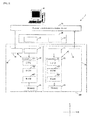
- FIG. 1 is a diagram illustrating the pairing system of one or more embodiments of first example of the present invention.
- a pairing system 1 of one or more embodiments of the present invention comprises a power supply device 10, which may include two power supply elements (exemplary details described below), a main body device 20 and an auxiliary device 30, each comprising power receiving elements, for example an antenna, (exemplary details described below).
- the main body device 20 and an auxiliary device 30 are packaged in a case 100.
- the power supply device 10 comprises power supply elements 11 and 12. Materials and shapes of the power supply elements 11, 12 are not limited in particular.
- each of the power supply elements 11, 12 may comprise a coil module having a shape that spirals toward a center of a spiral in a top surface view.
- the main body device 20 may be, for example, a main body in a set top box
- the auxiliary device 30 may be, for example, a device such as a remote controller or a headset in the set top box.
- the main body device 20 and the auxiliary device 30 comprise power receiving elements 21,31 that correspond to the power supply elements 11 and 12, respectively.
- the main body device 20 may further comprise a controller 22 and a memory 23, such as for example a flash ROM.
- the controller 22 may be a control means for controlling the entire main body device 20.
- the controller 22 includes a CPU 221, a ROM 222, and a RAM 223.
- the ROM 222 stores software and programs executed by the controller 22 and parameters and data needed to execute the software and the programs.
- the CPU 221 executes the various types of software and programs stored in the ROM 222.
- the RAM 223 temporarily stores data obtained during various types of processes and data obtained as a result of the various types of processes.
- the CPU 221, the ROM 222, the RAM 223, and the like are connected via a bus. A portion or an entirety of the CPU 221, the ROM 222, and the RAM 223 may be integrated into one chip.
- software for performing pairing setting is stored in the ROM 222.
- the software for performing pairing setting is started (executed)
- a process for pairing setting with another device is executed.
- the CPU 221 of the controller 22 executes the software for performing pairing setting stored in the RAM 222 when non-contact power supply between the power receiving element 21 and the power supply element 11 begins.
- Information, such as identification information of the auxiliary device 30 that will be described below, obtained by executing the software for performing pairing setting may be stored in the memory 23.
- the auxiliary device 30 further comprises a controller 32 and a memory 33, such as for example a flash ROM.
- the controller 32 may be a control means for controlling the entire auxiliary device 30.
- the controller 32 includes a CPU 321, a ROM 322, and a RAM 323.
- the ROM 322 stores software and programs executed by the controller 22 and parameters and data needed to execute the software and the programs.
- the CPU 321 executes the various types of software and programs stored in the ROM 322.
- the RAM 323 temporarily stores data obtained during various types of processes and data obtained as a result of the various types of processes.
- the CPU 321, the ROM 322, the RAM 323, and the like are connected via a bus. A portion or an entirety of the CPU 321, the ROM 322, and the RAM 323 may be integrated into one chip.
- software for performing pairing setting is stored in the ROM 322.
- the software for performing pairing setting is started (executed)
- a process for pairing setting with another device is executed.
- the CPU 321 of the controller 32 executes the software for performing pairing setting stored in the RAM 322 when non-contact power supply between the power receiving element 31 and the power supply element 12 begins.
- Identification information of the auxiliary device 30 may be stored in the memory 33. According to one or more embodiments, the stored identification information of the auxiliary device 30 may comprise, for example, a manufacture lot number.
- FIG. 2 is a flowchart illustrating an exemplary process leading to pairing completion.
- steps S01, S11 the controllers 22, 32 determine respectively whether non-contact power supply has begun. If non-contact power supply has begun (Y at steps S01, S11), the process proceeds to steps S02, S12, and if non-contact power supply has not begun, the process returns to steps S01, S11.
- starting non-contact power supply may supply power to the controllers 22, 32 and start the process in FIG. 2 .
- the process at and after steps S02, S12 may be performed without performing the determination at steps S01, S11.
- step S13 the controller 32 obtains identification information of its own device 30 from the memory 33 and superimposes this information on high-frequency power of the power supply device 10.
- the identification information of the auxiliary device 30 superimposed on high-frequency power is output to the controller 22 via non-contact power supply between the power supply element 11 and the power receiving element 21.
- step S03 it is determined whether the controller 22 obtained the identification information of the auxiliary device 30. If the identification information of the auxiliary device 30 has been obtained (Y at step S03), the process proceeds to step S04 and stores the identification information of the auxiliary device 30 in the memory 23. Pairing setting is thereby completed, and in the next and subsequent times, the auxiliary device 30 can be used with the main body device 20 without requiring pairing setting.
- the software for performing pairing setting is executed in two devices that are objects of pairing setting with non-contact power supply as a trigger.
- the software When the software is executed, one device outputs the identification information of its own device to another device, and the latter device stores the identification information. Pairing setting is thereby completed. Because this pairing setting is executed by starting non-contact power supply, pairing setting can be easily executed not only before but also after the two devices are packaged into one case.
- FIG. 3 is a diagram illustrating a pairing system of one or more embodiments of the present invention.
- the power supply element and the power receiving element functioned as the communication part.
- a main body device and an auxiliary device each comprise a communication part.
- a pairing system 1 of one or more embodiments of second example of the present invention comprises a power supply device 10 which may include power supply elements (exemplary details described below), a main body device 40 and an auxiliary device 50 including respective power receiving elements (exemplary details described below) and packaged in a case 100, and an external wireless communication device 70 connected to a ROM writer (personal computer) 60.
- the power supply device 10 comprises power supply elements 11 and 12. Materials and shapes of the power supply elements 11, 12 are not limited in particular. For example, a coil module having a shape that spirals toward a center of a spiral in a top surface view may be used.
- the main body device 40 is, for example, a main body in a set top box
- the auxiliary device 50 is, for example, a device such as a remote controller or a headset in the set top box.
- the main body device 40 and the auxiliary device 50 have power receiving elements 41, 51 that correspond to the power supply elements 11 and 12, respectively.
- the main body device 40 further comprises a controller 42, a memory 43 such as a flash ROM, and a communication part 44.
- the controller 42 may be a control means for controlling the entire main body device 40.
- the controller 42 includes a CPU 421, a ROM 422, and a RAM 423.
- the ROM 422 stores software and programs executed by the controller 42 and parameters and data needed to execute the software and the programs.
- the CPU 421 executes the various types of software and programs stored in the ROM 422.
- the RAM 423 temporarily stores data obtained during various types of processes and data obtained as a result of the various types of processes.
- the CPU 421, the ROM 422, the RAM 423, and the like are connected via a bus. A portion or an entirety of the CPU 421, the ROM 422, and the RAM 223 may be integrated into one chip.
- software for performing pairing setting is stored in the ROM 422.
- the software for performing pairing setting is started (executed)
- a process for pairing setting with another device is executed.
- the CPU 421 of the controller 42 executes the software for performing pairing setting stored in the RAM 422 when non-contact power supply between the power receiving element 41 and the power supply element 11 begins.
- Information (identification information of the auxiliary device 50 that will be described below) obtained by executing the software for performing pairing setting is stored in the memory 43.
- the communication part 44 sends and receives information with the external wireless communication device 70 that will be described below.
- the auxiliary device 50 further comprises a controller 52, a memory 53 such as a flash ROM, and a communication part 54.
- the controller 52 may be a control means for controlling the entire auxiliary device 50.
- the controller 52 comprises a CPU 521, a ROM 522, and a RAM 523.
- the ROM 522 stores software and programs executed by the controller 52 and parameters and data needed to execute the software and the programs.
- the CPU 521 executes the various types of software and programs stored in the ROM 522.
- the RAM 523 temporarily stores data obtained during various types of processes and data obtained as a result of the various types of processes.
- the CPU 521, the ROM 522, the RAM 523, and the like are connected via a bus. A portion or an entirety of the CPU 521, the ROM 522, and the RAM 523 may be integrated into one chip.
- software for performing pairing setting is stored in the ROM 522.
- the software for performing pairing setting is started (executed)
- a process for pairing setting with another device is executed.
- the CPU 521 of the controller 52 executes the software for performing pairing setting stored in the RAM 522 when non-contact power supply between the power receiving element 51 and the power supply element 12 begins.
- Identification information of the auxiliary device 50 is stored in the memory 53.
- the communication part 54 sends and receives information with the external wireless communication device 70 that will be described below.
- the ROM writer 60 is an information processing device such as a personal computer, and the external wireless communication device 70 is connected to the ROM writer 60.
- the ROM writer 60 and the communication part 44, 54 are connected by wireless communication such as Bluetooth, Wi-Fi (registered trademark), or P2P, and the communication parts 44 and 54 send and receive information via the external wireless communication device 70.
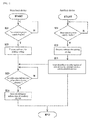
- FIG. 4 is a flowchart illustrating an exemplary process leading to pairing completion.
- steps S21, S31 the controllers 42, 52 determine respectively whether non-contact power supply has begun. If non-contact power supply has begun (Y at steps S21, S31), the process proceeds to steps S22, S32, and if non-contact power supply has not begun, the process returns to steps S21, S31. In a situation where the main body enclosure 40 and the auxiliary device 50 are packaged in the case 100, because starting non-contact power supply supplies power to the controllers 42, 52 and starts the process in FIG. 4 , in this situation, the process at and after steps S22, S32 may be performed without performing the determination at steps S21, S31.
- step S33 the controller 52 obtains identification information of its own device from the memory 53 and sends this information to the external wireless communication device 70 via the communication part 54.
- the identification information of the auxiliary device 50 sent to the external wireless communication device 70 is stored in the ROM writer 60 and, further, output to the controller 42 via the external wireless communication device 70 and the communication part 44.
- step S23 It is determined in step S23 whether the controller 42 obtained the identification information of the auxiliary device 50. If the identification information of the auxiliary device 50 has been obtained (Y at step S23), the process proceeds to step S24 and stores the identification information of the auxiliary device 50 in the memory 43. Pairing setting is thereby completed, and in the next and subsequent times, the auxiliary device 50 can be used with the main body device 40 without requiring pairing setting.
- FIG. 5 is a diagram illustrating a pairing system of one or more embodiments of a third example of the present invention.
- the main body device and the auxiliary device each comprises the communication part, and the identification information of the auxiliary device is sent and received via the external wireless communication device.
- a main body device and an auxiliary device may directly send and receive identification information of the auxiliary device.
- a pairing system 1 of one or more embodiments of the third example of the present invention may comprise a power supply device 10 including power supply elements (exemplary details described below) and a main body device 80 and an auxiliary device 90 including respective power receiving elements (exemplary details described below) packaged in a case 100.
- the power supply device 10 comprises power supply elements 11 and 12.
- Materials and shapes of the power supply elements 11, 12 are not limited in particular. For example, a coil module having a shape that spirals toward a center of a spiral in a top surface view may be used.
- the main body device 80 is, for example, a main body in a set top box
- the auxiliary device 90 is, for example, a device such as a remote controller or a headset in the set top box.
- the main body device 80 and the auxiliary device 90 have power receiving elements 81, 91 that correspond to the power supply elements 11 and 12, respectively.
- the main body device 80 further comprises a controller 82, a memory 83, such as for example a flash ROM, and a communication part 84.
- the controller 82 may be a control means for controlling the entire main body device 80.
- the controller 82 includes a CPU 821, a ROM 822, and a RAM 823.
- the ROM 822 stores software and programs executed by the controller 82 and parameters and data needed to execute the software and the programs.
- the CPU 821 executes the various types of software and programs stored in the ROM 822.
- the RAM 823 temporarily stores data obtained during various types of processes and data obtained as a result of the various types of processes.
- the CPU 821, the ROM 822, the RAM 823, and the like are connected via a bus. A portion or an entirety of the CPU 821, the ROM 822, and the RAM 223 may be integrated into one chip.
- software for performing pairing setting is stored in the ROM 822.
- the software for performing pairing setting is started (executed)
- a process for pairing setting with another device is executed.
- the CPU 821 of the controller 82 executes the software for performing pairing setting stored in the RAM 822 when non-contact power supply between the power receiving element 81 and the power supply element 11 begins.
- Information (identification information of the auxiliary device 90 that will be described below) obtained by executing the software for performing pairing setting is stored in the memory 83.
- the communication part 84 sends and receives information with the communication part 94 that will be described below.
- the auxiliary device 90 further comprises a controller 92, a memory 93 such as a flash ROM, and a communication part 94.
- the controller 92 may be a control means for controlling the entire auxiliary device 90.
- the controller 92 includes a CPU 921, a ROM 922, and a RAM 923.
- the ROM 922 stores software and programs executed by the controller 92 and parameters and data needed to execute the software and the programs.
- the CPU 921 executes the various types of software and programs stored in the ROM 922.
- the RAM 923 temporarily stores data obtained during various types of processes and data obtained as a result of the various types of processes.
- the CPU 921, the ROM 922, the RAM 923, and the like are connected via a bus. A portion or an entirety of the CPU 921, the ROM 922, and the RAM 223 may be integrated into one chip.
- software for performing pairing setting is stored in the ROM 922.
- the software for performing pairing setting is started (executed)
- a process for pairing setting with another device is executed.
- the CPU 921 of the controller 92 executes the software for performing pairing setting stored in the RAM 922 when non-contact power supply between the power receiving element 91 and the power supply element 12 begins.
- Identification information of the auxiliary device 90 is stored in the memory 93.
- the communication part 94 sends and receives information with the communication part 84.
- the communication part 84 and the communication part 94 are connected by wireless communication such as Bluetooth, Wi-Fi, or P2P.
- FIG. 6 is a flowchart illustrating an exemplary process leading to pairing completion.
- steps S41, S51 the controllers 82, 92 determine respectively whether non-contact power supply has begun. If non-contact power supply has begun (Y at steps S41, S51), the process proceeds to steps S42, S52, and if non-contact power supply has not begun, the process returns to steps S41, S51. In a situation where the main body enclosure 80 and the auxiliary device 90 are packaged in the case 100, because starting non-contact power supply supplies power to the controllers 82, 92 and starts the process in FIG. 6 , in this situation, the process at and after steps S42, S52 may be performed without performing the determination at steps S41, S51.
- identification information unique to the power supply device 10 is superimposed on high-frequency power of non-contact power supply.
- the CPUs 821, 921 of the controllers 82, 92 execute the software for pairing setting.
- the controllers 82, 92 extract the identification information of the power supply device 10 superimposed on high-frequency power of non-contact power supply.
- step S44 the controller 82 determines whether the identification information of the power supply device 10 extracted at step S43 matches the identification information of the power supply device 10 extracted by the controller 92 at step S53. If the identification information match (Y at step S44), the process proceeds to step S45, and if the identification information do not match, the process ends.
- the controller 82 requests the identification information of the auxiliary device 90 from the controller 92.
- the controller 92 obtains the identification information of its own device from the memory 93.
- the obtained identification information of its own device is output to the controller 82 via the communication part 94 and the communication part 84.
- step S46 It is determined in step S46 whether the controller 82 obtained the identification information of the auxiliary device 90. If the identification information of the auxiliary device 90 has been obtained (Y at step S46), the process proceeds to step S47 and stores the identification information of the auxiliary device 90 in the memory 83. Pairing setting is thereby completed, and in the next and subsequent times, the auxiliary device 90 can be used with the main body device 80 without requiring pairing setting.
- the software for pairing setting is executed with starting non-contact power supply as the trigger.
- the present invention is not limited thereto and may execute software for pairing setting when a signal that serves as a trigger for executing the software for pairing setting and that is superimposed on high-frequency power of non-contact power supply is received.
- FIG. 7 is a flowchart illustrating an exemplary process leading to pairing completion.
- a fourth example of the present invention will be described as a modified example of the first example but is also applicable to the second and third examples.
- Steps S61, S63 to S65, S71, and S73 to S74 in the flowchart in FIG. 7 may respectively be the same as steps S01, S02 to S04, S11, and S12 to S13, and descriptions thereof will therefore be omitted.
- controllers 22, 32 determine respectively whether the signal that serves as the trigger for pairing setting is superimposed on high-frequency power of non-contact power supply. If the signal that serves as the trigger for pairing setting is superimposed on high-frequency power of non-contact power supply (Y at steps S62, S72), the process proceeds to step S63, S73, and if the signal that serves as the trigger for pairing setting is not superimposed on high-frequency power of non-contact power supply (N at steps S62, S72), the process returns to steps S62, S72.
- pairing setting is only executed when the signal that serves as the trigger for pairing setting is superimposed on high-frequency power of non-contact power supply, pairing setting can be executed or updated at a desired timing.
- the identification information of the auxiliary device is sent and received by the communication part of the auxiliary device directly or indirectly communicating with the communication part of the main body device.
- a plurality of main body devices executes software for pairing setting and/or a plurality of auxiliary devices executes the software for pairing setting, there is a possibility that the main body device and the auxiliary device that the user desires are not paired. Therefore, one or more embodiments of a fifth example of the present invention provide a pairing system that can reliably perform pairing even in such a situation.
- Embodiments of the fifth example of the present invention will be described as a modified example of the third example but is of course also applicable to the first and fourth examples.
- a power supply device 10 superimposes a high frequency indicating identification information of the power supply device 10 on high-frequency power of non-contact power supply.
- Controllers 82, 92 obtain the identification information of the power supply device 10 superimposed on high-frequency power of non-contact power supply.
- the controllers 82, 92 can search a device having the identification information of the power supply device 10 (a same identification number as an extracted identification number of the power supply device) via communication parts 84, 94.
- the identification information of the auxiliary device 90 is stored in a memory 84 when the controller 82 searches the auxiliary device 90 as the auxiliary device having the identification information of the power supply device 10.
- the same effects as the second and third examples may be exhibited. Additionally, because objects for pairing setting are specified based on the identification information of the power supply device, pairing setting can be performed reliably even when there is the plurality of main body devices or the plurality of auxiliary devices.
Landscapes
- Engineering & Computer Science (AREA)
- Computer Networks & Wireless Communication (AREA)
- Signal Processing (AREA)
- Power Engineering (AREA)
- Computer Security & Cryptography (AREA)
- Selective Calling Equipment (AREA)
- Charge And Discharge Circuits For Batteries Or The Like (AREA)
- Direct Current Feeding And Distribution (AREA)
Abstract
Description
- The present invention relates to a pairing method and pairing system that associate and link two devices.
- When two devices are used in a one-to-one relation, such as a main body device and an auxiliary device of a remote controller or the like in a set top box, the main body device and the auxiliary device may be paired. Pairing is generating a common encryption key and the main device storing identification information (for example, a Bluetooth [registered trademark] address) of the auxiliary device after establishing, for example, a Bluetooth connection between the two devices. Storing the common encryption key and the identification information of the auxiliary device enables sending and receiving information with the auxiliary device without reconfiguration in a next and subsequent Bluetooth connection and executing functions of a connected device.
- However, because it is unclear in a manufacturing process which main body device is paired to which auxiliary device, a pairing setting generally needs to be set by purchasers of the device themselves and is time consuming. A manufacturer or seller of the device can perform the pairing setting immediately before packaging the main body device and the auxiliary device, but in this case, there is still a possibility that an enclosure may become scratched or dirty because setting is done by hand.
- [Patent Document 1] Japanese Unexamined Patent Application Publication No.
2003-69458 - A technique of pairing without contact by setting a communication mode from an external base station is disclosed in Patent Document 1, but this is time consuming because the communication mode needs to be set from the external base station.
- In one or more embodiments of the present invention, a pairing method and a pairing system pair two devices without requiring much time and without contact.
- In one or more embodiments, a method for pairing two devices, each of which may be configured to receive power from a power supply device and comprise a memory, may comprise detecting non-contact power supply from the power supply device, receiving the non-contact power supply and performing pairing setting of the two devices, and storing identification information of one of the two devices in the memory of the other device. For example, detecting non-contact power supply may comprise detecting non-contact power supply from the power supply to each of the two devices.
- The power supply device may include one or two power supply elements. For example, a single power supply element may be included in a pairing system which may also include the two devices. Alternatively, the power supply device may include two power supply elements. For example, the two power supply elements may be included in a pairing system which may also include the two devices.
- In one or more embodiments, when two power supply elements are provided, detecting non-contact power supply may be performed from a respective power supply element of the power supply device.
- In one or more embodiments, detecting non-contact power supply may comprise detecting non-contact power supply from a respective power supply element of the power supply device to each of the two devices.
- Each of the two devices may include a power receiving element. In this case, in one or more embodiments, detecting non-contact power supply may comprise detecting non-contact power supply from a respective power supply element of the power supply device to a corresponding power receiving element of the two devices.
- In one or more embodiments, non-contact power supply may trigger pairing setting.
- In one or more embodiments, pairing setting is performed once the non-contact power supply is received. For example, pairing setting may be performed once the non-contact power supply is received by the two devices. However, pairing setting may be performed, for example, in response to a signal. For example, a signal serving as a trigger for performing pairing setting may be superimposed, for example, on high-frequency power of non-contact power supply.
- In one or more embodiments, performing pairing setting of the two devices may comprise executing software configured to perform pairing setting. For example, by executing the software configured to perform pairing setting, information identifying one of the two devices may be obtained. For example, information identifying one of the two devices may be previously stored in the memory of the respective device.
- In one or more embodiments, the method may further comprise outputting the identification information of the one device to the other device via the power supply device to store the identification information of the one device in the memory of the other device.
- Furthermore, in the pairing method according to one or more embodiments of the present invention, each of the two devices may further comprise a wireless communication part, such as, for example, a wireless terminal. In this case, the method may further comprise outputting the identification information of the one device to the other device over wireless communication by the wireless communication part to store the identification information of the one device in the memory of the other device.
- Furthermore, in one or more embodiments of the present invention, each of the two devices may further comprise the wireless communication part, and the method may further comprise outputting the identification information of the one device to the other device over wireless communication by the wireless communication part via an external wireless communication device to store the identification information of the one device in the memory provided by the other device.
- Furthermore, in one or more embodiments of the present invention, two devices that perform pairing setting may further comprise the wireless communication part, and the method may further comprise outputting the identification information of the one device to the other device over wireless communication by the wireless communication part via an external wireless communication device to store the identification information of the one device in the memory provided by the other device.
- Furthermore, in one or more embodiments of the present invention, the method may further comprise extracting identification information of the power supply device and searching for a device having the identification information of the power supply device, wherein between the two devices having the identification information of the power supply device, the identification information of the one device is stored in the memory of the other device.
- A pairing system of one or more embodiments of the present invention may comprise a power supply device. Further, the pairing system may further comprise a first device and a second device, each configured to perform pairing setting. The first device may comprise a first power receiving element configured to receive non-contact power supply from the power supply device, and a first controller configured to obtain identification information of the first device and to detect power supply to the first power receiving element to perform the pairing setting. The second device may comprise a second power receiving element configured to receive non-contact power supply from the power supply device, a second controller configured to detect power supply to the second power receiving element to perform the pairing setting, and a memory configured to store the identification information of the first device obtained by the second controller from the first controller.
- A pairing system of one or more embodiments of the present invention may comprise a power supply device which may include a first power supply element and a second power supply element. Further, the pairing system may further comprise a first device and a second device, each configured to perform pairing setting. The first device may comprise a first power receiving element configured to receive non-contact power supply from the first power supply element, and a first controller configured to obtain identification information of the first device and to detect power supply to the first power receiving element to perform the pairing setting. The second device may comprise a second power receiving element configured to receive non-contact power supply from the second power supply element, a second controller configured to detect power supply to the second power receiving element to perform the pairing setting, and a memory configured to store the identification information of the first device obtained by the second controller from the first controller.
- Furthermore, in one or more embodiments of the present invention, the first device may further comprise a memory. In such a case, the first controller may be further configured to obtain identification information of the first device from the memory of the first device.
- Furthermore, in one or more embodiments of the present invention, the first controller may be configured to input the identification information of the first device. Further, the power supply device may be configured to output the input identification information of the first device to the second controller.
- Furthermore, in one or more embodiments of the present invention, the first device and the second device may each comprise a wireless communication part. The first controller may be configured to output the identification information of the first device to the second controller over wireless communication by the wireless communication part.
- Furthermore, in one or more embodiments of the present invention, the first device and the second device may each comprise a wireless communication part, and the first controller may be configured to output the identification information of the first device to the second controller over wireless communication by the wireless communication part via an external wireless communication device.
- For example, each of the wireless communication parts of the first device and the second device may be a wireless terminal.
- Furthermore, in one or more embodiments of the present invention, the first controller and the second controller may be each configured to extract identification information of the power supply device. The first controller may be configured to output the identification information of the first device to the second controller having the identification information of the power supply device.
- In one or more embodiments of the present invention, the power supply device may comprise a coil. When the power supply device comprises a first and a second power supply element, each power supply element may be a coil.
- In one or more embodiments of the present invention, each of the first power receiving element and of the second power receiving element may be an antenna.
- According to one or more embodiments of the present invention, the non-contact power supply may trigger a pairing setting in two devices. In paring setting, one device outputs the identification information of its own device to another device, and the latter device stores the identification information. Pairing setting is thereby completed. Because this pairing setting may be executed by starting non-contact power supply, pairing setting can be easily executed not only before but also after the two devices are packaged into one case.
-
-
FIG. 1 is a diagram illustrating a pairing system of one or more embodiments of a first example of the present invention. -
FIG. 2 is a flowchart illustrating a process of pairing in the pairing system of one or more embodiments of the first example. -
FIG. 3 is a diagram illustrating a pairing system of one or more embodiments of a second example of the present invention. -
FIG. 4 is a flowchart illustrating a process of pairing in the pairing system of one or more embodiments of the second example. -
FIG. 5 is a diagram illustrating a pairing system of one or more embodiments of a third example of the present invention. -
FIG. 6 is a flowchart illustrating a process of pairing in the pairing system of one or more embodiments of the third example. -
FIG. 7 is a flowchart illustrating a process of pairing in a pairing system of one or more embodiments of a fourth example of the present invention. - Embodiments of a pairing method and pairing system will be described below with reference to drawings. One or more embodiments of the present invention illustrate examples of the pairing method and the pairing system for embodying a technical concept of the present invention and are not meant to specify the present invention to these pairing methods and pairing systems, being equally applicable to pairing methods and pairing systems of other embodiments included in the scope of patent claims.
-
FIG. 1 is a diagram illustrating the pairing system of one or more embodiments of first example of the present invention. A pairing system 1 of one or more embodiments of the present invention comprises apower supply device 10, which may include two power supply elements (exemplary details described below), amain body device 20 and anauxiliary device 30, each comprising power receiving elements, for example an antenna, (exemplary details described below). In the embodiment ofFig. 1 , themain body device 20 and anauxiliary device 30 are packaged in acase 100. Thepower supply device 10 comprisespower supply elements power supply elements power supply elements - The
main body device 20 may be, for example, a main body in a set top box, and theauxiliary device 30 may be, for example, a device such as a remote controller or a headset in the set top box. Themain body device 20 and theauxiliary device 30 comprisepower receiving elements power supply elements - When AC power is supplied to the
power supply elements FIG. 1 ). An induced current is excited in thepower receiving element power supply elements power supply elements power receiving elements - The
main body device 20 may further comprise acontroller 22 and amemory 23, such as for example a flash ROM. Thecontroller 22 may be a control means for controlling the entiremain body device 20. Thecontroller 22 includes aCPU 221, aROM 222, and aRAM 223. TheROM 222 stores software and programs executed by thecontroller 22 and parameters and data needed to execute the software and the programs. TheCPU 221 executes the various types of software and programs stored in theROM 222. TheRAM 223 temporarily stores data obtained during various types of processes and data obtained as a result of the various types of processes. TheCPU 221, theROM 222, theRAM 223, and the like are connected via a bus. A portion or an entirety of theCPU 221, theROM 222, and theRAM 223 may be integrated into one chip. - In one or more embodiments of the present invention, software for performing pairing setting is stored in the
ROM 222. When the software for performing pairing setting is started (executed), a process for pairing setting with another device is executed. - Specifically, the
CPU 221 of thecontroller 22 executes the software for performing pairing setting stored in theRAM 222 when non-contact power supply between thepower receiving element 21 and thepower supply element 11 begins. Information, such as identification information of theauxiliary device 30 that will be described below, obtained by executing the software for performing pairing setting may be stored in thememory 23. - The
auxiliary device 30 further comprises acontroller 32 and amemory 33, such as for example a flash ROM. Thecontroller 32 may be a control means for controlling the entireauxiliary device 30. Thecontroller 32 includes aCPU 321, aROM 322, and aRAM 323. TheROM 322 stores software and programs executed by thecontroller 22 and parameters and data needed to execute the software and the programs. TheCPU 321 executes the various types of software and programs stored in theROM 322. TheRAM 323 temporarily stores data obtained during various types of processes and data obtained as a result of the various types of processes. TheCPU 321, theROM 322, theRAM 323, and the like are connected via a bus. A portion or an entirety of theCPU 321, theROM 322, and theRAM 323 may be integrated into one chip. - In one or more embodiments of the present invention, software for performing pairing setting is stored in the
ROM 322. When the software for performing pairing setting is started (executed), a process for pairing setting with another device is executed. - Specifically, the
CPU 321 of thecontroller 32 executes the software for performing pairing setting stored in theRAM 322 when non-contact power supply between thepower receiving element 31 and thepower supply element 12 begins. Identification information of theauxiliary device 30 may be stored in thememory 33. According to one or more embodiments, the stored identification information of theauxiliary device 30 may comprise, for example, a manufacture lot number. - An exemplary process from start to end of the pairing setting in the pairing system 1 according to one or more embodiments of the present invention will be described below with reference to
FIG. 2. FIG. 2 is a flowchart illustrating an exemplary process leading to pairing completion. - In steps S01, S11, the
controllers main body enclosure 20 and theauxiliary device 30 are packaged in thecase 100, starting non-contact power supply may supply power to thecontrollers FIG. 2 . In this case, the process at and after steps S02, S12 may be performed without performing the determination at steps S01, S11. - At steps S02, S12, the
CPUs controllers controller 32 obtains identification information of itsown device 30 from thememory 33 and superimposes this information on high-frequency power of thepower supply device 10. The identification information of theauxiliary device 30 superimposed on high-frequency power is output to thecontroller 22 via non-contact power supply between thepower supply element 11 and thepower receiving element 21. - In step S03, it is determined whether the
controller 22 obtained the identification information of theauxiliary device 30. If the identification information of theauxiliary device 30 has been obtained (Y at step S03), the process proceeds to step S04 and stores the identification information of theauxiliary device 30 in thememory 23. Pairing setting is thereby completed, and in the next and subsequent times, theauxiliary device 30 can be used with themain body device 20 without requiring pairing setting. - According to one or more embodiments of the present invention, the software for performing pairing setting is executed in two devices that are objects of pairing setting with non-contact power supply as a trigger. When the software is executed, one device outputs the identification information of its own device to another device, and the latter device stores the identification information. Pairing setting is thereby completed. Because this pairing setting is executed by starting non-contact power supply, pairing setting can be easily executed not only before but also after the two devices are packaged into one case.
-
FIG. 3 is a diagram illustrating a pairing system of one or more embodiments of the present invention. In the first example, the power supply element and the power receiving element functioned as the communication part. In one or more embodiments of the second example, a main body device and an auxiliary device each comprise a communication part. - A pairing system 1 of one or more embodiments of second example of the present invention comprises a
power supply device 10 which may include power supply elements (exemplary details described below), amain body device 40 and anauxiliary device 50 including respective power receiving elements (exemplary details described below) and packaged in acase 100, and an externalwireless communication device 70 connected to a ROM writer (personal computer) 60. Thepower supply device 10 comprisespower supply elements power supply elements - The
main body device 40 is, for example, a main body in a set top box, and theauxiliary device 50 is, for example, a device such as a remote controller or a headset in the set top box. Themain body device 40 and theauxiliary device 50 havepower receiving elements 41, 51 that correspond to thepower supply elements - When AC power is supplied to the
power supply elements FIG. 3 ). An induced current is excited in thepower receiving element 41, 51 brought near thepower supply elements - The
main body device 40 further comprises a controller 42, amemory 43 such as a flash ROM, and acommunication part 44. The controller 42 may be a control means for controlling the entiremain body device 40. The controller 42 includes aCPU 421, aROM 422, and aRAM 423. TheROM 422 stores software and programs executed by the controller 42 and parameters and data needed to execute the software and the programs. TheCPU 421 executes the various types of software and programs stored in theROM 422. TheRAM 423 temporarily stores data obtained during various types of processes and data obtained as a result of the various types of processes. TheCPU 421, theROM 422, theRAM 423, and the like are connected via a bus. A portion or an entirety of theCPU 421, theROM 422, and theRAM 223 may be integrated into one chip. - In one or more embodiments of the present invention, software for performing pairing setting is stored in the
ROM 422. When the software for performing pairing setting is started (executed), a process for pairing setting with another device is executed. - Specifically, the
CPU 421 of the controller 42 executes the software for performing pairing setting stored in theRAM 422 when non-contact power supply between thepower receiving element 41 and thepower supply element 11 begins. Information (identification information of theauxiliary device 50 that will be described below) obtained by executing the software for performing pairing setting is stored in thememory 43. Thecommunication part 44 sends and receives information with the externalwireless communication device 70 that will be described below. - The
auxiliary device 50 further comprises acontroller 52, amemory 53 such as a flash ROM, and acommunication part 54. Thecontroller 52 may be a control means for controlling the entireauxiliary device 50. Thecontroller 52 comprises aCPU 521, aROM 522, and a RAM 523. TheROM 522 stores software and programs executed by thecontroller 52 and parameters and data needed to execute the software and the programs. TheCPU 521 executes the various types of software and programs stored in theROM 522. The RAM 523 temporarily stores data obtained during various types of processes and data obtained as a result of the various types of processes. TheCPU 521, theROM 522, the RAM 523, and the like are connected via a bus. A portion or an entirety of theCPU 521, theROM 522, and the RAM 523 may be integrated into one chip. - In one or more embodiments of the present invention, software for performing pairing setting is stored in the
ROM 522. When the software for performing pairing setting is started (executed), a process for pairing setting with another device is executed. - Specifically, the
CPU 521 of thecontroller 52 executes the software for performing pairing setting stored in theRAM 522 when non-contact power supply between the power receiving element 51 and thepower supply element 12 begins. Identification information of theauxiliary device 50 is stored in thememory 53. As the identification information of theauxiliary device 50 stored in one or more embodiments of the present invention, a manufacture lot number, a Bluetooth address, a MAC address, and an IP address are illustrated. Thecommunication part 54 sends and receives information with the externalwireless communication device 70 that will be described below. - The
ROM writer 60 is an information processing device such as a personal computer, and the externalwireless communication device 70 is connected to theROM writer 60. TheROM writer 60 and thecommunication part communication parts wireless communication device 70. - A process from when pairing setting starts to when pairing setting ends in the pairing system 1 of one or more embodiments of the present invention will be described below with reference to
FIG. 4. FIG. 4 is a flowchart illustrating an exemplary process leading to pairing completion. - In steps S21, S31, the
controllers 42, 52 determine respectively whether non-contact power supply has begun. If non-contact power supply has begun (Y at steps S21, S31), the process proceeds to steps S22, S32, and if non-contact power supply has not begun, the process returns to steps S21, S31. In a situation where themain body enclosure 40 and theauxiliary device 50 are packaged in thecase 100, because starting non-contact power supply supplies power to thecontrollers 42, 52 and starts the process inFIG. 4 , in this situation, the process at and after steps S22, S32 may be performed without performing the determination at steps S21, S31. - At steps S22, S32, the
CPUs controllers 42, 52 execute the software for pairing setting. In step S33, thecontroller 52 obtains identification information of its own device from thememory 53 and sends this information to the externalwireless communication device 70 via thecommunication part 54. The identification information of theauxiliary device 50 sent to the externalwireless communication device 70 is stored in theROM writer 60 and, further, output to the controller 42 via the externalwireless communication device 70 and thecommunication part 44. - It is determined in step S23 whether the controller 42 obtained the identification information of the
auxiliary device 50. If the identification information of theauxiliary device 50 has been obtained (Y at step S23), the process proceeds to step S24 and stores the identification information of theauxiliary device 50 in thememory 43. Pairing setting is thereby completed, and in the next and subsequent times, theauxiliary device 50 can be used with themain body device 40 without requiring pairing setting. - According to one or more embodiments of the present invention, the same effects as one or more embodiments of the first example may be exhibited.
-
FIG. 5 is a diagram illustrating a pairing system of one or more embodiments of a third example of the present invention. In the second example, the main body device and the auxiliary device each comprises the communication part, and the identification information of the auxiliary device is sent and received via the external wireless communication device. However, a main body device and an auxiliary device may directly send and receive identification information of the auxiliary device. - A pairing system 1 of one or more embodiments of the third example of the present invention may comprise a
power supply device 10 including power supply elements (exemplary details described below) and a main body device 80 and an auxiliary device 90 including respective power receiving elements (exemplary details described below) packaged in acase 100. Thepower supply device 10 comprisespower supply elements power supply elements - The main body device 80 is, for example, a main body in a set top box, and the auxiliary device 90 is, for example, a device such as a remote controller or a headset in the set top box. The main body device 80 and the auxiliary device 90 have
power receiving elements 81, 91 that correspond to thepower supply elements - When AC power is supplied to the
power supply elements FIG. 5 ). An induced current is excited in thepower receiving element 81, 91 brought near thepower supply elements - The main body device 80 further comprises a
controller 82, a memory 83, such as for example a flash ROM, and acommunication part 84. Thecontroller 82 may be a control means for controlling the entire main body device 80. Thecontroller 82 includes aCPU 821, a ROM 822, and a RAM 823. The ROM 822 stores software and programs executed by thecontroller 82 and parameters and data needed to execute the software and the programs. TheCPU 821 executes the various types of software and programs stored in the ROM 822. The RAM 823 temporarily stores data obtained during various types of processes and data obtained as a result of the various types of processes. TheCPU 821, the ROM 822, the RAM 823, and the like are connected via a bus. A portion or an entirety of theCPU 821, the ROM 822, and theRAM 223 may be integrated into one chip. - In one or more embodiments of the present invention, software for performing pairing setting is stored in the ROM 822. When the software for performing pairing setting is started (executed), a process for pairing setting with another device is executed.
- Specifically, the
CPU 821 of thecontroller 82 executes the software for performing pairing setting stored in the RAM 822 when non-contact power supply between thepower receiving element 81 and thepower supply element 11 begins. Information (identification information of the auxiliary device 90 that will be described below) obtained by executing the software for performing pairing setting is stored in the memory 83. Thecommunication part 84 sends and receives information with thecommunication part 94 that will be described below. - The auxiliary device 90 further comprises a controller 92, a memory 93 such as a flash ROM, and a
communication part 94. The controller 92 may be a control means for controlling the entire auxiliary device 90. The controller 92 includes a CPU 921, aROM 922, and aRAM 923. TheROM 922 stores software and programs executed by the controller 92 and parameters and data needed to execute the software and the programs. The CPU 921 executes the various types of software and programs stored in theROM 922. TheRAM 923 temporarily stores data obtained during various types of processes and data obtained as a result of the various types of processes. The CPU 921, theROM 922, theRAM 923, and the like are connected via a bus. A portion or an entirety of the CPU 921, theROM 922, and theRAM 223 may be integrated into one chip. - In one or more embodiments of the present invention, software for performing pairing setting is stored in the
ROM 922. When the software for performing pairing setting is started (executed), a process for pairing setting with another device is executed. - Specifically, the CPU 921 of the controller 92 executes the software for performing pairing setting stored in the
RAM 922 when non-contact power supply between the power receiving element 91 and thepower supply element 12 begins. Identification information of the auxiliary device 90 is stored in the memory 93. As the identification information of the auxiliary device 90 stored in one or more embodiments of the present invention, a manufacture lot number, a Bluetooth address, a MAC address, and an IP address are illustrated. Thecommunication part 94 sends and receives information with thecommunication part 84. Thecommunication part 84 and thecommunication part 94 are connected by wireless communication such as Bluetooth, Wi-Fi, or P2P. - A process from start to end of the pairing setting in the pairing system 1 will be described below with reference to
FIG. 6. FIG. 6 is a flowchart illustrating an exemplary process leading to pairing completion. - In steps S41, S51, the
controllers 82, 92 determine respectively whether non-contact power supply has begun. If non-contact power supply has begun (Y at steps S41, S51), the process proceeds to steps S42, S52, and if non-contact power supply has not begun, the process returns to steps S41, S51. In a situation where the main body enclosure 80 and the auxiliary device 90 are packaged in thecase 100, because starting non-contact power supply supplies power to thecontrollers 82, 92 and starts the process inFIG. 6 , in this situation, the process at and after steps S42, S52 may be performed without performing the determination at steps S41, S51. - In one or more embodiments of the present invention, identification information unique to the power supply device 10 (for example, information indicating the manufacture lot number) is superimposed on high-frequency power of non-contact power supply.
- At steps S42, S52, the
CPUs 821, 921 of thecontrollers 82, 92 execute the software for pairing setting. - At steps S43, S53, the
controllers 82, 92 extract the identification information of thepower supply device 10 superimposed on high-frequency power of non-contact power supply. - At step S44, the
controller 82 determines whether the identification information of thepower supply device 10 extracted at step S43 matches the identification information of thepower supply device 10 extracted by the controller 92 at step S53. If the identification information match (Y at step S44), the process proceeds to step S45, and if the identification information do not match, the process ends. - At step S45, the
controller 82 requests the identification information of the auxiliary device 90 from the controller 92. - At step S54, the controller 92 obtains the identification information of its own device from the memory 93. The obtained identification information of its own device is output to the
controller 82 via thecommunication part 94 and thecommunication part 84. - It is determined in step S46 whether the
controller 82 obtained the identification information of the auxiliary device 90. If the identification information of the auxiliary device 90 has been obtained (Y at step S46), the process proceeds to step S47 and stores the identification information of the auxiliary device 90 in the memory 83. Pairing setting is thereby completed, and in the next and subsequent times, the auxiliary device 90 can be used with the main body device 80 without requiring pairing setting. - According to one or more embodiments of the present invention, the same effects as one or more embodiments of the first example may be exhibited.
- In one or more embodiments of the present invention described above, the software for pairing setting is executed with starting non-contact power supply as the trigger. However, the present invention is not limited thereto and may execute software for pairing setting when a signal that serves as a trigger for executing the software for pairing setting and that is superimposed on high-frequency power of non-contact power supply is received.
- A process from start to end of a pairing setting in a pairing system 1 will be described below with reference to
FIG. 7. FIG. 7 is a flowchart illustrating an exemplary process leading to pairing completion. One or more embodiments of a fourth example of the present invention will be described as a modified example of the first example but is also applicable to the second and third examples. - Steps S61, S63 to S65, S71, and S73 to S74 in the flowchart in
FIG. 7 may respectively be the same as steps S01, S02 to S04, S11, and S12 to S13, and descriptions thereof will therefore be omitted. - At steps S62, S72,
controllers - According to one or more embodiments of the present invention, the same effects as the first example may be exhibited. Additionally, because the software for pairing setting is only executed when the signal that serves as the trigger for pairing setting is superimposed on high-frequency power of non-contact power supply, pairing setting can be executed or updated at a desired timing.
- In the second and third examples, the identification information of the auxiliary device is sent and received by the communication part of the auxiliary device directly or indirectly communicating with the communication part of the main body device. However, if a plurality of main body devices executes software for pairing setting and/or a plurality of auxiliary devices executes the software for pairing setting, there is a possibility that the main body device and the auxiliary device that the user desires are not paired. Therefore, one or more embodiments of a fifth example of the present invention provide a pairing system that can reliably perform pairing even in such a situation.
- Embodiments of the fifth example of the present invention will be described as a modified example of the third example but is of course also applicable to the first and fourth examples. In one or more embodiments of the fifth example of the present invention, a
power supply device 10 superimposes a high frequency indicating identification information of thepower supply device 10 on high-frequency power of non-contact power supply.Controllers 82, 92 obtain the identification information of thepower supply device 10 superimposed on high-frequency power of non-contact power supply. - Furthermore, the
controllers 82, 92 can search a device having the identification information of the power supply device 10 (a same identification number as an extracted identification number of the power supply device) viacommunication parts memory 84 when thecontroller 82 searches the auxiliary device 90 as the auxiliary device having the identification information of thepower supply device 10. - According to one or more embodiments of the fifth example of the present invention, the same effects as the second and third examples may be exhibited. Additionally, because objects for pairing setting are specified based on the identification information of the power supply device, pairing setting can be performed reliably even when there is the plurality of main body devices or the plurality of auxiliary devices.
- Although the disclosure has been described with respect to only a limited number of embodiments, those skilled in the art, having benefit of this disclosure, will appreciate that various other embodiments may be devised without departing from the scope of the present invention. Accordingly, the scope of the invention should be limited only by the attached claims.
-
- 1
- Pairing system
- 10
- Power supply device
- 11, 12
- Power supply element
- 20, 40, 80
- Main body device
- 21, 41, 81
- Power receiving element
- 22, 42, 82
- Controller
- 23, 43, 83
- Memory
- 30, 50, 90
- Auxiliary device
- 31, 51, 91
- Power receiving element
- 32, 52, 92
- Controller
- 33, 53, 93
- Memory
- 44, 84
- Communication part
- 54, 94
- Communication part
- 60
- ROM writer
- 70
- External wireless communication device
Claims (15)
- A method for pairing two devices (20, 30; 40, 50; 80, 90), each of the devices (20, 30; 40, 50; 80, 90) being configured to receive power from a power supply device (10) and comprising a memory (23, 33; 43, 53; 83, 93), the method comprising:detecting non-contact power supply from the power supply device (10);receiving the non-contact power supply and performing pairing setting of the two devices (20, 30; 40, 50; 80, 90); andstoring identification information of one of the two devices (30; 50; 90) in the memory (23; 43; 83) of the other device (20; 40; 80).
- The pairing method of claim 1, wherein detecting non-contact power supply comprises detecting non-contact power supply from a respective power supply element (11, 12) of the power supply device (10) to a corresponding power receiving element (21, 31; 41, 51; 81, 91) of the two devices (20, 30; 40, 50; 80, 90).
- The pairing method according to claim 1 or claim 2, further comprising:outputting the identification information of the one device (30; 50; 90) to the other device (20; 40; 80) via the power supply device (10) to store the identification information of the one device (30; 50; 90) in the memory (23; 43; 83) of the other device (20; 40; 80).
- The pairing method according to any one of claims 1-3, wherein
each of the two devices (20, 30; 40, 50; 80, 90) further comprises a wireless communication part (44, 54; 84; 94), and
the method further comprises outputting the identification information of the one device (30; 50; 90) to the other device (20; 40; 80) over wireless communication by the wireless communication part (44, 54; 84; 94) to store the identification information of the one device (30; 50; 90) in the memory (23; 43; 83) of the other device (20; 40; 80). - The pairing method according to claim 4, wherein
outputting the identification information of the one device (30; 50; 90) to the other device (20; 40; 80) over wireless communication by the wireless communication part (44, 54; 84; 94) is performed via an external wireless communication device (70). - The pairing method according to any of claims 1 to 5, further comprising:extracting identification information of the power supply device (10) and searching for a device having the identification information of the power supply device (10), whereinbetween the two devices (20, 30; 40, 50; 80, 90) having the identification information of the power supply device (10), the identification information of the one device (30; 50; 90) is stored in the memory (23; 43; 83) of the other device (20; 40; 80).
- Apairing system (1), comprising:a power supply device (10);a first device (30; 50; 90) and a second device (20; 40; 80) each configured to perform pairing setting, wherein
the first device (30; 50; 90) comprises:a first power receiving element (31; 51; 91) configured to receive non-contact power supply from the power supply device (10); anda first controller (32; 52; 92) configured to obtain identification information of the first device (30; 50) and to detect power supply to the first power receiving element (31; 51; 91) to perform the pairing setting; andthe second device (20; 40; 80) comprises:a second power receiving element (21; 41; 81) configured to receive non-contact power supply from the power supply device (10);a second controller (22; 42; 82) configured to detect power supply to the second power receiving element (21; 41; 81) to perform the pairing setting; anda memory (23; 43; 83) configured to store the identification information of the first device (30; 50; 90) obtained by the second controller (22; 42; 82) from the first controller (32; 52; 92). - The pairing system (1) according to claim 7, wherein the first device (30; 50; 90) further comprises a memory (33; 53; 93) and wherein the first controller (32; 52; 92) is further configured to obtain identification information of the first device (30; 50) from the memory (33; 53; 93) of the first device (30; 50; 90).
- The pairing system (1) according to claim 7 or claim 8, wherein:the first controller (32; 52; 92) is configured to input the identification information of the first device (30; 50; 90), andthe power supply device (10) is configured to output the input identification information of the first device (30; 50; 90) to the second controller (22; 42; 82).
- The pairing system (1) according to claim 7 or claim 8, wherein:the first device (50; 90) and the second device (40; 80) each comprise a wireless communication part (54, 44; 94, 84), andthe first controller (52; 92) is configured to output the identification information of the first device (50; 90) to the second controller (42; 82) over wireless communication by the wireless communication part (54, 44; 94, 84).
- The pairing system (1) according to claim 7 or claim 8, wherein:the first device (50; 90) and the second device (40; 80) each comprise a wireless communication part (54, 44; 94, 84), andthe first controller (52; 92) is configured to output the identification information of the first device (50; 90) to the second controller (42; 82) over wireless communication by the wireless communication part (54, 44; 94, 84) via an external wireless communication device (70).
- The pairing system (1) according to claim 10 or claim 11, wherein each of the wireless communication parts (54, 44; 94, 84) of the first device (50; 90) and the second device (40; 80) is a wireless terminal.
- The pairing system (1) according to any of the claims 7 to 12, wherein:the first controller (92) and the second controller (82) are each configured to extract identification information of the power supply device (10), and the first controller (92) is configured to output the identification information of the first device (90) to the second controller (82) having the identification information of the power supply device (10).
- The pairing system (1) according to any one of claims 7-13, wherein each power supply element (12, 11) is a coil.
- The pairing system (1) according to any of claims 7-14, wherein each of the first power receiving element (31; 51; 91) and of the second power receiving element (21; 41; 81) is an antenna.
Applications Claiming Priority (1)
| Application Number | Priority Date | Filing Date | Title |
|---|---|---|---|
| JP2013102265A JP2014222843A (en) | 2013-05-14 | 2013-05-14 | Pairing method and pairing system |
Publications (2)
| Publication Number | Publication Date |
|---|---|
| EP2804283A2 true EP2804283A2 (en) | 2014-11-19 |
| EP2804283A3 EP2804283A3 (en) | 2015-04-01 |
Family
ID=50735854
Family Applications (1)
| Application Number | Title | Priority Date | Filing Date |
|---|---|---|---|
| EP14167430.9A Withdrawn EP2804283A3 (en) | 2013-05-14 | 2014-05-07 | Pairing method and pairing system |
Country Status (3)
| Country | Link |
|---|---|
| US (1) | US20140342664A1 (en) |
| EP (1) | EP2804283A3 (en) |
| JP (1) | JP2014222843A (en) |
Cited By (1)
| Publication number | Priority date | Publication date | Assignee | Title |
|---|---|---|---|---|
| CN108668266A (en) * | 2018-04-19 | 2018-10-16 | 浙江东胜物联技术有限公司 | One kind one matches two blue Tooth remote controllers |
Citations (1)
| Publication number | Priority date | Publication date | Assignee | Title |
|---|---|---|---|---|
| JP2003069458A (en) | 2001-08-28 | 2003-03-07 | Nippon Telegr & Teleph Corp <Ntt> | Electromagnetic induction communication module, portable terminal and communication system |
Family Cites Families (4)
| Publication number | Priority date | Publication date | Assignee | Title |
|---|---|---|---|---|
| US9350170B2 (en) * | 2010-01-26 | 2016-05-24 | Broadcom Corporation | Smart power management system and related method |
| EP3584675B1 (en) * | 2011-01-11 | 2023-10-18 | Avago Technologies International Sales Pte. Limited | Smart powering and pairing system and related method |
| WO2012109286A1 (en) * | 2011-02-08 | 2012-08-16 | Hewlette-Packard Development Company, L.P. | System and method for linking and sharing resources amongst devices |
| WO2012109364A2 (en) * | 2011-02-08 | 2012-08-16 | Hewlett-Packard Development Company, L.P. | Graphic notification feedback for indicating inductive coupling amongst devices |
-
2013
- 2013-05-14 JP JP2013102265A patent/JP2014222843A/en active Pending
-
2014
- 2014-05-07 EP EP14167430.9A patent/EP2804283A3/en not_active Withdrawn
- 2014-05-09 US US14/274,016 patent/US20140342664A1/en not_active Abandoned
Patent Citations (1)
| Publication number | Priority date | Publication date | Assignee | Title |
|---|---|---|---|---|
| JP2003069458A (en) | 2001-08-28 | 2003-03-07 | Nippon Telegr & Teleph Corp <Ntt> | Electromagnetic induction communication module, portable terminal and communication system |
Cited By (1)
| Publication number | Priority date | Publication date | Assignee | Title |
|---|---|---|---|---|
| CN108668266A (en) * | 2018-04-19 | 2018-10-16 | 浙江东胜物联技术有限公司 | One kind one matches two blue Tooth remote controllers |
Also Published As
| Publication number | Publication date |
|---|---|
| JP2014222843A (en) | 2014-11-27 |
| EP2804283A3 (en) | 2015-04-01 |
| US20140342664A1 (en) | 2014-11-20 |
Similar Documents
| Publication | Publication Date | Title |
|---|---|---|
| JP5499534B2 (en) | Non-contact power receiving apparatus, power receiving method in non-contact power receiving apparatus, and non-contact power feeding system | |
| US10306558B2 (en) | Power receiving apparatus for wirelessly receiving power from external apparatus | |
| KR20170112934A (en) | Method and apparatus for transmitting a wireless power | |
| KR102489729B1 (en) | Electronic device for connecting external devices based on connection information and operating method thereof | |
| KR102801229B1 (en) | electronic device and method for authenticating of the same | |
| CN106412293B (en) | Foreign matter detection method and device and terminal equipment | |
| CN104868607A (en) | Power Transfer Unit And Power Transfer Method | |
| US20150244180A1 (en) | Power supply apparatus, power supply method, and storage medium | |
| EP3573214B1 (en) | Feeding device and method for controlling same | |
| JP2015233392A (en) | Electronic apparatus | |
| US10114394B2 (en) | Information processing apparatus, connection device, communication device, information processing method, and program | |
| CN104620256B (en) | For the method and circuit being tuned to the antenna circuit for actively launching label | |
| KR20200101237A (en) | Device for wireless power transmission and operating method thereof | |
| EP2804283A2 (en) | Pairing method and pairing system | |
| JP2016067076A (en) | Power supply device, control method, and program | |
| KR20210015467A (en) | A wireless charging device communicating with an electronic device and a communication method of the wireless charging device | |
| JP5734774B2 (en) | Electronics | |
| KR20210039109A (en) | Electronic device for transmitting/receiving data and method thereof | |
| KR20200105302A (en) | Method for wireless communication expand and electronic device thereof | |
| KR20230055796A (en) | Electronic device for wirelessly transmitting power and method of operating the same | |
| JP7278356B2 (en) | Power supply device, power receiving device, control method and program | |
| KR101596761B1 (en) | Method and apparatus for wireless charging using priority order information | |
| KR20200041720A (en) | electronic device and power control method for wireless charging | |
| CN105188155B (en) | A kind of method and terminal of network connection | |
| JP2016032280A (en) | COMMUNICATION DEVICE, ITS CONTROL METHOD, AND PROGRAM |
Legal Events
| Date | Code | Title | Description |
|---|---|---|---|
| PUAI | Public reference made under article 153(3) epc to a published international application that has entered the european phase |
Free format text: ORIGINAL CODE: 0009012 |
|
| 17P | Request for examination filed |
Effective date: 20140507 |
|
| AK | Designated contracting states |
Kind code of ref document: A2 Designated state(s): AL AT BE BG CH CY CZ DE DK EE ES FI FR GB GR HR HU IE IS IT LI LT LU LV MC MK MT NL NO PL PT RO RS SE SI SK SM TR |
|
| AX | Request for extension of the european patent |
Extension state: BA ME |
|
| PUAL | Search report despatched |
Free format text: ORIGINAL CODE: 0009013 |
|
| AK | Designated contracting states |
Kind code of ref document: A3 Designated state(s): AL AT BE BG CH CY CZ DE DK EE ES FI FR GB GR HR HU IE IS IT LI LT LU LV MC MK MT NL NO PL PT RO RS SE SI SK SM TR |
|
| AX | Request for extension of the european patent |
Extension state: BA ME |
|
| RIC1 | Information provided on ipc code assigned before grant |
Ipc: H04W 12/04 20090101ALI20150225BHEP Ipc: H02J 5/00 20060101AFI20150225BHEP |
|
| STAA | Information on the status of an ep patent application or granted ep patent |
Free format text: STATUS: THE APPLICATION IS DEEMED TO BE WITHDRAWN |
|
| 18D | Application deemed to be withdrawn |
Effective date: 20151002 |