EP2804261B1 - Anschlussleiste - Google Patents
Anschlussleiste Download PDFInfo
- Publication number
- EP2804261B1 EP2804261B1 EP14168281.5A EP14168281A EP2804261B1 EP 2804261 B1 EP2804261 B1 EP 2804261B1 EP 14168281 A EP14168281 A EP 14168281A EP 2804261 B1 EP2804261 B1 EP 2804261B1
- Authority
- EP
- European Patent Office
- Prior art keywords
- insulating body
- plane
- junction block
- fastening
- transverse
- Prior art date
- Legal status (The legal status is an assumption and is not a legal conclusion. Google has not performed a legal analysis and makes no representation as to the accuracy of the status listed.)
- Active
Links
Images

Classifications
-
- H—ELECTRICITY
- H01—ELECTRIC ELEMENTS
- H01R—ELECTRICALLY-CONDUCTIVE CONNECTIONS; STRUCTURAL ASSOCIATIONS OF A PLURALITY OF MUTUALLY-INSULATED ELECTRICAL CONNECTING ELEMENTS; COUPLING DEVICES; CURRENT COLLECTORS
- H01R9/00—Structural associations of a plurality of mutually-insulated electrical connecting elements, e.g. terminal strips or terminal blocks; Terminals or binding posts mounted upon a base or in a case; Bases therefor
- H01R9/22—Bases, e.g. strip, block, panel
- H01R9/24—Terminal blocks
- H01R9/26—Clip-on terminal blocks for side-by-side rail- or strip-mounting
- H01R9/2608—Fastening means for mounting on support rail or strip
Definitions
- the present invention relates to the field of electrical devices of the terminal block type for the connection of a low voltage electrical appliance.
- terminal blocks are mainly intended to equip electrical cabinets or electrical boxes of industrial machines.
- the reduction of this space is associated in part with the reduction in the size of the terminal blocks, in particular the reduction of their overall depth.
- a terminal block comprising an insulating body delimited by two substantially parallel lateral planes, and a movable fixing foot connected to a connection zone of the rear face of the insulating body and intended to hold the terminal block on a terminal block. rail support.
- such a terminal block comprises connection terminals to a conductive wire disposed on its upper face and its lower face.
- These terminals for connecting to a wire are distributed on both sides on the depth of the terminal block and have a minimum distance to maintain a good use.
- the bulk of the fixing foot prevents the connection terminals to a conductive wire on one of these two faces to be arranged further towards the rear of the terminal block, which results in relatively large terminal blocks of depth inducing a significant bulk.
- a terminal block corresponding to the preamble of claim 1 is described in the document EP 1182735 A2 .
- the present invention aims to solve all or part of the disadvantages mentioned above.
- the present invention relates to a terminal block as defined by the subject of claim 1.
- This arrangement makes it possible to reduce the overall depth of the terminal block and thus its bulk in an electrical cabinet or an electrical box while retaining good functionality of use of the terminal block.
- This arrangement allows to gather all the elastic branches at the same location on the same side relative to the housing of the connection terminal so as to further reduce the footprint of the mounting foot.
- the length of the at least two elastic branches defined between the connection zone of the rear face of the insulating body and the fixing member is greater than the maximum thickness of the fixing member defined in FIG. a transverse plane in the foreground.
- This arrangement makes it possible to maintain good efficiency of the elastic branches while reducing the bulk of the fastener.
- the retaining member comprises the wall of a housing formed in the fastener.
- This arrangement facilitates the maintenance of the tool on the retainer.
- the housing has a reinforcing rib.
- This arrangement increases the robustness of the fixing foot and therefore of the terminal block.
- the insulating body comprises a lug intended to limit the relative movement between an edge of the support rail and the fixing means of the fastener.
- This arrangement makes it possible to preserve the fastening means of the member from a bad mounting or an excessive action of the support rail.
- the fixing means of the fixing member comprise a lug for providing a support for an edge of the support rail.
- This arrangement makes it possible to grip the support rail between these edges and to limit the mechanical clearance between the terminal block and the support rail.
- the fastening foot is movable between a first rest position and at least a second position in which the lug of the insulating body is opposite the lug of the fastening means of the fastener member. fixation.
- the fastener has a normal I-shaped profile.
- This arrangement reduces the thickness of the fastener while maintaining good rigidity.
- the fixing foot comprises three elastic branches.
- This arrangement makes it possible to reinforce the force exerted by the elastic limbs and gives strength to the fixing foot.
- connection terminal is movable within its housing, two of the housing walls transverse to the two lateral planes delimiting the insulating body being arranged to guide the movement of the connection terminal.
- This arrangement makes it possible to minimize the volume of the housing while maintaining good mobility of the connection terminal inside said terminal block.
- the overall depth of the terminal block is less than 80 mm, preferably equal to 78.4 mm.
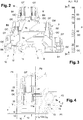
- a junction block 1 according to the invention comprises an insulating body 2 defined by two substantially parallel lateral planes PL1, PL2.
- the insulating body 2 has in particular an upper face 3, a lower face 4 and a rear face 5.
- the upper face 3 and the lower face 4 have a profile in the form of stairs.
- the upper face has three terminals for connection to a conductor wire B1, B2, B3 and the lower face has three other terminals for connection to a conductor B4, B5, B6.
- Each of these terminals for connection to a conductor wire B1, B2, B3, B4, B5, B6 is movable in translation inside a housing 20 relative to a connection bar 7a, 7b, 7c fixed to the inside the insulating body 2.
- each of the housings 20 open a first opening OT and a second opening OC arranged transversely relative to each other.
- Each first opening OC is arranged on a step of the stepped profile of the upper 3 and lower 4 faces and is intended for the introduction of an electrical conductor into the connection terminal B1, B2, B3, B4, B5, B6.
- Each second opening OT is disposed on a step against the staircase profile of the upper 3 and lower 4 faces and is intended for the introduction of a tool, for example of the screwdriver type, allowing the setting of the connection terminal B1, B2, B3, B4, B5, B6 and in particular its tightening or loosening.
- the cage of the terminal B1, B2, B3, B4, B5, B6 is guided by two side walls 21, 22 of the housing 20.
- the junction block 1 also comprises a movable fixing leg 10 connected to a connecting zone 5a of the rear face 5 of the insulating body 2 and for holding the junction block 1 on a support rail (not shown).
- the attachment foot 10 comprises three elastic branches 11a, 11b, 11c connecting the connection zone 5a of the rear face 5 of the insulating body 2 and a connection zone 12a of a fixing member 12.
- the fastener 12 has an elongate shape with a normal I-shaped profile, and extends in a general direction D between a first end 13 and a second end 14.
- the first end 13 comprises attachment means 15 for interacting with a first edge of the support rail.
- these fixing means 15 cooperate with second fixing means 8 disposed on the rear face 5 of the insulating body 2 and intended to interact with a second edge of the support rail so as to maintain the terminal block 1 on the support rail .
- these second attachment means 8 are formed by a notch into which the second edge of the support rail is inserted.
- the fixing means 15 comprise a lug 16 forming a shoulder on which can rest the first edge of the support rail.
- the insulating body 2 also comprises a lug 6 intended to limit the relative movement between the first edge of the support rail and the fixing means 15 of the fixing member 12.
- the attachment foot 10 is movable between a first rest position and at least a second position in which the lug 6 of the insulating body 2 is opposite the lug 16 of the means fixing the fixing member 12.
- the second end 14 comprises a retaining member 17 for locking the tool (not shown) so as to move the attachment foot 10 against the force exerted by the three elastic branches 11a, 11b, 11c.
- the retaining member 17 comprises the wall of a housing (not shown) formed on the second end 14 of the fastener 12.
- This housing is intended to accommodate the end of the tool so as to limit the sliding of this end of the tool on the fastener 12.
- this housing comprises a reinforcing rib (not shown) so as to limit the deformation of the housing under the action of the tool.
- the terminal B6 may be arranged on a greater depth of the lower face 4 of the terminal block 1 than it would be on a terminal block according to the state of the art.
- the length of the three elastic branches 11a, 11b, 11c defined between the connection zone 5a of the rear face 5 of the insulating body 2 and the The connection zone 12a of the fastener 12 is greater than the maximum thickness e of the fastener 12 defined in a plane transverse to the first plane P1.
- the arrangement of the terminal of the terminal B6 as well as the reduction of the thickness of the fixing foot make it possible to obtain a terminal block with an overall depth P less than that of a terminal block of the state of the art. .
- a junction block 1 according to the invention comprises an overall depth of less than 80 mm, and preferably equal to 78.4 mm.
Landscapes
- Connections Arranged To Contact A Plurality Of Conductors (AREA)
- Installation Of Indoor Wiring (AREA)
Claims (10)
- Klemmleiste (1), umfassend:- einen isolierenden Körper (2), der von zwei im Wesentlichen parallelen seitlichen Ebenen (PL1, PL2) begrenzt ist,- einen Fixierungsfuß (10), der beweglich mit einer Verbindungszone (5a) der hinteren Seite (5) des isolierenden Körpers (2) verknüpft und ausgelegt ist, um die Klemmleiste (1) auf einer Trageschiene zu halten,wobei der Fixierungsfuß (10) mindestens zwei elastische Schenkel (11a, 11b, 11c) umfasst, die die Verbindungszone (5a) der hinteren Seite (5a) des isolierenden Körpers (2) und eine Verbindungszone (12a) eines Fixierungsorgans (12) verknüpfen,
wobei das Fixierungsorgan (12) eine verlängerte Form darstellt, die sich gemäß einer allgemeinen Richtung (D) zwischen einem ersten Ende (13), umfassend Fixierungsmittel (15), die ausgelegt sind, um mit einem Rand der Trageschiene zu interagieren, und einem zweiten Ende (14) erstreckt, umfassend ein Rückhalteorgan (17), das ausgelegt ist, um ein Werkzeug zu blockieren, um den Fixierungsfuß (10) gegen die Kraft, ausgeübt von den mindestens zwei elastischen Schenkeln (11a, 11b, 11c), verschieben zu können,
wobei die Klemmleiste (1) mindestens eine Aufnahme (20) für eine Anschlussklemme (B6) umfasst, wobei sich die Aufnahme (20) mindestens teilweise im Inneren eines Volumens (V) erstreckt, das durch Folgendes begrenzt ist:- eine erste Ebene (P1), quer zu den zwei seitlichen Ebenen (PL1, PL2), die den isolierenden Körper (2) begrenzen, im Wesentlichen parallel zur allgemeinen Richtung (D), die das erste Ende (13) und das zweite Ende (14) des Fixierungsorgans (12) aneinanderfügen und die Verbindungszone (12a) des Fixierungsorgans (12) queren, und- eine zweite Ebene (P2), quer zu den zwei seitlichen Ebenen (PL1, PL2), die den isolierenden Körper (2) begrenzen, die im Wesentlichen parallel zur ersten Ebene (P1) ist und die Verbindungszone (5a) der hinteren Seite (5) quert,- mindestens eine dritte Ebene (P3), quer zu den zwei seitlichen Ebenen (PL1, PL2), die den isolierenden Körper (2) begrenzen, im Wesentlichen quer zur ersten Ebene (P1) und zur zweiten Ebene (P2), und die durch den entferntesten elastischen Schenkel (11a) der Fixierungsmittel (15) verläuft, die ausgelegt sind, um mit einem Rand der Trageschiene zu interagieren, und- mindestens eine vierte Ebene (P4), quer zu den zwei seitlichen Ebenen (PL1, PL2), die den isolierenden Körper (2) begrenzen, im Wesentlichen quer zur ersten Ebene (P1) und zur zweiten Ebene (P2), und durch das Rückhalteorgan (17) verlaufen, das ausgelegt ist, um ein Werkzeug zu blockieren,wobei die Klemmleiste (1) dadurch gekennzeichnet ist, dass sich alle elastischen Schenkel (11a, 11b, 11c) an einer gleichen Stelle einer gleichen Seite mit Bezug auf die Aufnahme (20) der Anschlussklemme (B6) befinden. - Klemmleiste (1) nach Anspruch 1, wobei die Länge der mindestens zwei elastischen Schenkel (11a, 11b, 11c), die zwischen der Verbindungszone (5a) der hinteren Seite (5) des isolierenden Körpers (2) und dem Fixierungsorgan (12) definiert ist, größer als die maximale Dicke des Fixierungsorgans (12) ist, die auf einer Querebene zur ersten Ebene (P1) definiert ist.
- Klemmleiste (1) nach einem der Ansprüche 1 oder 2, wobei das Rückhalteorgan (17) die Wand einer Aufnahme umfasst, die im Fixierungsorgan (12) angebracht ist.
- Klemmleiste (1) nach Anspruch 3, wobei die Aufnahme eine Verstärkungsrippe aufweist.
- Klemmleiste (1) nach einem der Ansprüche 1 bis 4, wobei der isolierende Körper (2) einen Dorn (6) umfasst, der ausgelegt ist, um die relative Bewegung zwischen einem Rand der Trageschiene und den Fixierungsmitteln (15) des Fixierungsorgans (12) zu begrenzen.
- Klemmleiste (1) nach einem der Ansprüche 1 bis 5, wobei die Fixierungsmittel (15) des Fixierungsorgans (12) einen Dorn (16) umfassen, der ausgelegt ist, um ein Auflage für einen Rand des Schienenträgers anzubringen.
- Klemmleiste (1) nach Anspruch 5 und 6, wobei der Fixierungsfuß (10) zwischen einer ersten Ruheposition und einer zweiten Position beweglich ist, wobei der Dorn (6) des isolierenden Körpers (2) gegenüber dem Dorn (16) der Fixierungsmittel (15) des Fixierungsorgans (12) ist.
- Klemmleiste (1) nach einem der Ansprüche 1 bis 7, wobei das Fixierungsorgan (12) ein normales Profil in Form eines I darstellt.
- Klemmleiste (1) nach einem der Ansprüche 1 bis 8, wobei der Fixierungsfuß (10) drei elastische Schenkel (11a, 11b, 11c) umfasst.
- Klemmleiste (1) nach einem der Ansprüche 1 bis 9, wobei die Anschlussklemme (B6) im Inneren ihrer Aufnahme (20) beweglich ist, wobei zwei der Wände der Aufnahme (21, 22), quer zu den zwei seitlichen Ebenen (PL1, PL2), die den isolierenden Körper (2) begrenzen, angeordnet sind, um die Bewegung der Anschlussklemme (B6) zu führen.
Applications Claiming Priority (1)
| Application Number | Priority Date | Filing Date | Title |
|---|---|---|---|
| FR1354452A FR3005801B1 (fr) | 2013-05-17 | 2013-05-17 | Bloc de jonction |
Publications (2)
| Publication Number | Publication Date |
|---|---|
| EP2804261A1 EP2804261A1 (de) | 2014-11-19 |
| EP2804261B1 true EP2804261B1 (de) | 2018-10-24 |
Family
ID=48980015
Family Applications (1)
| Application Number | Title | Priority Date | Filing Date |
|---|---|---|---|
| EP14168281.5A Active EP2804261B1 (de) | 2013-05-17 | 2014-05-14 | Anschlussleiste |
Country Status (5)
| Country | Link |
|---|---|
| US (1) | US9306298B2 (de) |
| EP (1) | EP2804261B1 (de) |
| CN (1) | CN104167621B (de) |
| FR (1) | FR3005801B1 (de) |
| RU (1) | RU2649970C2 (de) |
Families Citing this family (3)
| Publication number | Priority date | Publication date | Assignee | Title |
|---|---|---|---|---|
| USD765039S1 (en) * | 2014-04-16 | 2016-08-30 | Weidmueller Interface Gmbh & Co. Kg | Terminal block |
| EP3054533B1 (de) * | 2015-02-05 | 2020-01-29 | Morsettitalia S.p.A. | Basisreihenklemmenblock und zusätzlicher reihenklemmenblock für switchboards und zweistöckige reihenklemmenblockanordnung mit basisreihenklemmenblock und zusätzlichem reihenklemmenblock |
| USD952577S1 (en) * | 2020-02-05 | 2022-05-24 | Dehn Se | Surge protection device |
Family Cites Families (14)
| Publication number | Priority date | Publication date | Assignee | Title |
|---|---|---|---|---|
| SU1076988A1 (ru) * | 1982-06-18 | 1984-02-29 | Всесоюзный Ордена Трудового Красного Знамени Научно-Исследовательский,Проектно-Конструкторский И Технологический Институт Релестроения | Клеммна колодка |
| DE10041279C2 (de) * | 2000-08-22 | 2002-11-21 | Phoenix Contact Gmbh & Co | Elektrische Reihenklemme |
| DE20114612U1 (de) * | 2001-09-05 | 2003-01-16 | Weidmüller Interface GmbH & Co., 32760 Detmold | Reihenklemme mit Schneidkontakten und Anschlußvorrichtung |
| US7011551B2 (en) * | 2004-05-06 | 2006-03-14 | Johansen Arnold W | Electrical terminal block |
| DE102005040657A1 (de) * | 2005-08-26 | 2007-03-15 | Phoenix Contact Gmbh & Co. Kg | Elektrische Anschlussklemme |
| DE102005050267B4 (de) * | 2005-10-20 | 2007-12-27 | Phoenix Contact Gmbh & Co. Kg | Reihenklemme |
| DE102007041979B3 (de) * | 2007-09-05 | 2009-03-19 | Conrad Stanztechnik Gmbh | Stromschienenanordnung für eine elektrische Anschlussvorrichtung, insbesondere eine Neutral-Leiter-Schutzklemme, eine Schutzleiterklemme und eine Reihenklemme |
| EP2206200B1 (de) * | 2007-10-23 | 2013-02-13 | Abb Ag | Reihenklemme mit einem verbinder |
| RU89772U1 (ru) * | 2009-08-19 | 2009-12-10 | Закрытое акционерное общество Промышленная группа "Метран" | Соединительная клемма для зажимного соединения без пайки выводов сенсора и преобразователя сигнала в измерителе температуры (варианты) |
| FR2951349B1 (fr) * | 2009-10-14 | 2017-03-24 | Auxel | Repartiteur de courant a barres conductrices |
| DE102010033808B4 (de) * | 2010-08-09 | 2016-12-22 | Phoenix Contact Gmbh & Co. Kg | Reihenklemme |
| DE202010013453U1 (de) * | 2010-09-23 | 2010-11-25 | Wago Verwaltungsgesellschaft Mbh | Rastmodul |
| DE102011115637B4 (de) * | 2011-06-21 | 2014-03-27 | Phoenix Contact Gmbh & Co. Kg | Elektrische Anschlussklemme |
| US20140113502A1 (en) * | 2012-09-28 | 2014-04-24 | Phoenix Contact Development & Manufacturing, Inc. | Connector Block with Spring-Loaded Electrical Terminal Assemblies |
-
2013
- 2013-05-17 FR FR1354452A patent/FR3005801B1/fr not_active Expired - Fee Related
-
2014
- 2014-05-14 RU RU2014119195A patent/RU2649970C2/ru not_active IP Right Cessation
- 2014-05-14 EP EP14168281.5A patent/EP2804261B1/de active Active
- 2014-05-16 CN CN201410207040.3A patent/CN104167621B/zh active Active
- 2014-05-19 US US14/281,637 patent/US9306298B2/en active Active
Non-Patent Citations (1)
| Title |
|---|
| None * |
Also Published As
| Publication number | Publication date |
|---|---|
| RU2649970C2 (ru) | 2018-04-06 |
| CN104167621A (zh) | 2014-11-26 |
| CN104167621B (zh) | 2018-03-13 |
| EP2804261A1 (de) | 2014-11-19 |
| FR3005801A1 (fr) | 2014-11-21 |
| US9306298B2 (en) | 2016-04-05 |
| FR3005801B1 (fr) | 2016-10-21 |
| US20140342618A1 (en) | 2014-11-20 |
| RU2014119195A (ru) | 2015-11-20 |
Similar Documents
| Publication | Publication Date | Title |
|---|---|---|
| EP2940798B1 (de) | Steckverbinder | |
| EP0183587B1 (de) | Mehrkontaktverbinderelement mit Mitteln zur Festlegung eines isolierenden Blocks im Gehäuse eines solchen Verbinderelements | |
| EP2804261B1 (de) | Anschlussleiste | |
| EP3451466B1 (de) | Verbindungsvorrichtung von zwei leiterelementen einer versorgungsschiene | |
| FR2743448A1 (fr) | Agencement d'interconnexion pour appareillage electrique, notamment pour appareillage de type bloc de jonction, et boitier equipe d'un tel agencement | |
| EP2112713A1 (de) | Anschlussklemme und Niederspannungs-Elektrogerät | |
| EP1643600B1 (de) | Vorrichtung zum elektrischen und mechanischen Verbinden eines elektrischen Anschlusselements | |
| FR3039009B1 (fr) | Dispositif de connexion electrique libre en translation avec protection contre les dommages par corps etrangers | |
| EP2680379B1 (de) | Kombination aus modularen schaltgeräte mit verriegelungsvorrichtung auf einer montageschiene | |
| FR2899725A1 (fr) | Bloc accumulateur pour l'alimentation d'appareils electriques | |
| WO2018059694A1 (fr) | Système de liaison électrique avec une lame conductrice | |
| EP3520176B1 (de) | Reihenklemme, bestehend aus einem elektrischen anschlusssystem verbindungssystem mit zwei verbindungsverzweigungen | |
| WO2018059696A1 (fr) | Système de liaison électrique avec un ressort à lames additionnel | |
| EP3369137B1 (de) | Anordnung von elektrischen halte- und kontaktvorrichtungen zum verbinden einer anschlussleiste und verschiedenen vorrichtungen zum halten und platzieren eines elektrischen kontakts für leiter | |
| EP1550190A2 (de) | Befestigungs und kontakteinrichtung für sammelschienen | |
| FR2917911A1 (fr) | Coffret destine a recevoir un appareillage electrique | |
| EP0848450B1 (de) | Anschlussvorrichtung von elektrischen Kabel mit ein oder einer Mehrzahl vom Leitern | |
| EP3076486A1 (de) | Steckverbinder und reihe von steckverbindern für anschlussblock | |
| FR2870394A1 (fr) | Grille de connexion de cables electriques | |
| FR2896626A1 (fr) | Bloc de borne de connexion | |
| EP2843769B1 (de) | Elektrische Anschlussvorrichtung einer Stromversorgungsquelle an ein Elektrogerät, entsprechendes Elektrogerät und entsprechendes elektrisches Anschlussverfahren | |
| FR2978366A1 (fr) | Ensemble femelle de connexion d'un poste a souder | |
| FR3043003A1 (fr) | Pince multiprise | |
| FR2913536A1 (fr) | Bloc de jonction destine a etre fixe sur un rail de support | |
| FR2794291A1 (fr) | Borne elastique a insert de butee |
Legal Events
| Date | Code | Title | Description |
|---|---|---|---|
| PUAI | Public reference made under article 153(3) epc to a published international application that has entered the european phase |
Free format text: ORIGINAL CODE: 0009012 |
|
| 17P | Request for examination filed |
Effective date: 20140514 |
|
| AK | Designated contracting states |
Kind code of ref document: A1 Designated state(s): AL AT BE BG CH CY CZ DE DK EE ES FI FR GB GR HR HU IE IS IT LI LT LU LV MC MK MT NL NO PL PT RO RS SE SI SK SM TR |
|
| AX | Request for extension of the european patent |
Extension state: BA ME |
|
| R17P | Request for examination filed (corrected) |
Effective date: 20150414 |
|
| RBV | Designated contracting states (corrected) |
Designated state(s): AL AT BE BG CH CY CZ DE DK EE ES FI FR GB GR HR HU IE IS IT LI LT LU LV MC MK MT NL NO PL PT RO RS SE SI SK SM TR |
|
| RAP1 | Party data changed (applicant data changed or rights of an application transferred) |
Owner name: ABB TECHNOLOGY AG |
|
| STAA | Information on the status of an ep patent application or granted ep patent |
Free format text: STATUS: EXAMINATION IS IN PROGRESS |
|
| RAP1 | Party data changed (applicant data changed or rights of an application transferred) |
Owner name: ABB SCHWEIZ AG |
|
| 17Q | First examination report despatched |
Effective date: 20170331 |
|
| GRAP | Despatch of communication of intention to grant a patent |
Free format text: ORIGINAL CODE: EPIDOSNIGR1 |
|
| STAA | Information on the status of an ep patent application or granted ep patent |
Free format text: STATUS: GRANT OF PATENT IS INTENDED |
|
| RIC1 | Information provided on ipc code assigned before grant |
Ipc: H01R 9/26 20060101AFI20180413BHEP |
|
| INTG | Intention to grant announced |
Effective date: 20180516 |
|
| GRAS | Grant fee paid |
Free format text: ORIGINAL CODE: EPIDOSNIGR3 |
|
| GRAA | (expected) grant |
Free format text: ORIGINAL CODE: 0009210 |
|
| STAA | Information on the status of an ep patent application or granted ep patent |
Free format text: STATUS: THE PATENT HAS BEEN GRANTED |
|
| AK | Designated contracting states |
Kind code of ref document: B1 Designated state(s): AL AT BE BG CH CY CZ DE DK EE ES FI FR GB GR HR HU IE IS IT LI LT LU LV MC MK MT NL NO PL PT RO RS SE SI SK SM TR |
|
| REG | Reference to a national code |
Ref country code: CH Ref legal event code: EP |
|
| REG | Reference to a national code |
Ref country code: IE Ref legal event code: FG4D Free format text: LANGUAGE OF EP DOCUMENT: FRENCH |
|
| REG | Reference to a national code |
Ref country code: AT Ref legal event code: REF Ref document number: 1057792 Country of ref document: AT Kind code of ref document: T Effective date: 20181115 |
|
| REG | Reference to a national code |
Ref country code: DE Ref legal event code: R096 Ref document number: 602014034513 Country of ref document: DE |
|
| REG | Reference to a national code |
Ref country code: NL Ref legal event code: MP Effective date: 20181024 |
|
| REG | Reference to a national code |
Ref country code: LT Ref legal event code: MG4D Ref country code: DE Ref legal event code: R081 Ref document number: 602014034513 Country of ref document: DE Owner name: TYCO ELECTRONICS SERVICES GMBH, CH Free format text: FORMER OWNER: ABB SCHWEIZ AG, BADEN, CH Ref country code: DE Ref legal event code: R081 Ref document number: 602014034513 Country of ref document: DE Owner name: TE CONNECTIVITY SERVICES GMBH, CH Free format text: FORMER OWNER: ABB SCHWEIZ AG, BADEN, CH |
|
| REG | Reference to a national code |
Ref country code: AT Ref legal event code: MK05 Ref document number: 1057792 Country of ref document: AT Kind code of ref document: T Effective date: 20181024 |
|
| RAP2 | Party data changed (patent owner data changed or rights of a patent transferred) |
Owner name: TYCO ELECTRONICS SERVICES GMBH |
|
| PG25 | Lapsed in a contracting state [announced via postgrant information from national office to epo] |
Ref country code: NL Free format text: LAPSE BECAUSE OF FAILURE TO SUBMIT A TRANSLATION OF THE DESCRIPTION OR TO PAY THE FEE WITHIN THE PRESCRIBED TIME-LIMIT Effective date: 20181024 |
|
| REG | Reference to a national code |
Ref country code: GB Ref legal event code: 732E Free format text: REGISTERED BETWEEN 20190307 AND 20190313 |
|
| PG25 | Lapsed in a contracting state [announced via postgrant information from national office to epo] |
Ref country code: FI Free format text: LAPSE BECAUSE OF FAILURE TO SUBMIT A TRANSLATION OF THE DESCRIPTION OR TO PAY THE FEE WITHIN THE PRESCRIBED TIME-LIMIT Effective date: 20181024 Ref country code: NO Free format text: LAPSE BECAUSE OF FAILURE TO SUBMIT A TRANSLATION OF THE DESCRIPTION OR TO PAY THE FEE WITHIN THE PRESCRIBED TIME-LIMIT Effective date: 20190124 Ref country code: LV Free format text: LAPSE BECAUSE OF FAILURE TO SUBMIT A TRANSLATION OF THE DESCRIPTION OR TO PAY THE FEE WITHIN THE PRESCRIBED TIME-LIMIT Effective date: 20181024 Ref country code: PL Free format text: LAPSE BECAUSE OF FAILURE TO SUBMIT A TRANSLATION OF THE DESCRIPTION OR TO PAY THE FEE WITHIN THE PRESCRIBED TIME-LIMIT Effective date: 20181024 Ref country code: AT Free format text: LAPSE BECAUSE OF FAILURE TO SUBMIT A TRANSLATION OF THE DESCRIPTION OR TO PAY THE FEE WITHIN THE PRESCRIBED TIME-LIMIT Effective date: 20181024 Ref country code: HR Free format text: LAPSE BECAUSE OF FAILURE TO SUBMIT A TRANSLATION OF THE DESCRIPTION OR TO PAY THE FEE WITHIN THE PRESCRIBED TIME-LIMIT Effective date: 20181024 Ref country code: IS Free format text: LAPSE BECAUSE OF FAILURE TO SUBMIT A TRANSLATION OF THE DESCRIPTION OR TO PAY THE FEE WITHIN THE PRESCRIBED TIME-LIMIT Effective date: 20190224 Ref country code: ES Free format text: LAPSE BECAUSE OF FAILURE TO SUBMIT A TRANSLATION OF THE DESCRIPTION OR TO PAY THE FEE WITHIN THE PRESCRIBED TIME-LIMIT Effective date: 20181024 Ref country code: BG Free format text: LAPSE BECAUSE OF FAILURE TO SUBMIT A TRANSLATION OF THE DESCRIPTION OR TO PAY THE FEE WITHIN THE PRESCRIBED TIME-LIMIT Effective date: 20190124 Ref country code: LT Free format text: LAPSE BECAUSE OF FAILURE TO SUBMIT A TRANSLATION OF THE DESCRIPTION OR TO PAY THE FEE WITHIN THE PRESCRIBED TIME-LIMIT Effective date: 20181024 |
|
| PG25 | Lapsed in a contracting state [announced via postgrant information from national office to epo] |
Ref country code: AL Free format text: LAPSE BECAUSE OF FAILURE TO SUBMIT A TRANSLATION OF THE DESCRIPTION OR TO PAY THE FEE WITHIN THE PRESCRIBED TIME-LIMIT Effective date: 20181024 Ref country code: PT Free format text: LAPSE BECAUSE OF FAILURE TO SUBMIT A TRANSLATION OF THE DESCRIPTION OR TO PAY THE FEE WITHIN THE PRESCRIBED TIME-LIMIT Effective date: 20190224 Ref country code: GR Free format text: LAPSE BECAUSE OF FAILURE TO SUBMIT A TRANSLATION OF THE DESCRIPTION OR TO PAY THE FEE WITHIN THE PRESCRIBED TIME-LIMIT Effective date: 20190125 Ref country code: SE Free format text: LAPSE BECAUSE OF FAILURE TO SUBMIT A TRANSLATION OF THE DESCRIPTION OR TO PAY THE FEE WITHIN THE PRESCRIBED TIME-LIMIT Effective date: 20181024 Ref country code: RS Free format text: LAPSE BECAUSE OF FAILURE TO SUBMIT A TRANSLATION OF THE DESCRIPTION OR TO PAY THE FEE WITHIN THE PRESCRIBED TIME-LIMIT Effective date: 20181024 |
|
| REG | Reference to a national code |
Ref country code: DE Ref legal event code: R097 Ref document number: 602014034513 Country of ref document: DE |
|
| PG25 | Lapsed in a contracting state [announced via postgrant information from national office to epo] |
Ref country code: CZ Free format text: LAPSE BECAUSE OF FAILURE TO SUBMIT A TRANSLATION OF THE DESCRIPTION OR TO PAY THE FEE WITHIN THE PRESCRIBED TIME-LIMIT Effective date: 20181024 Ref country code: DK Free format text: LAPSE BECAUSE OF FAILURE TO SUBMIT A TRANSLATION OF THE DESCRIPTION OR TO PAY THE FEE WITHIN THE PRESCRIBED TIME-LIMIT Effective date: 20181024 |
|
| PG25 | Lapsed in a contracting state [announced via postgrant information from national office to epo] |
Ref country code: SM Free format text: LAPSE BECAUSE OF FAILURE TO SUBMIT A TRANSLATION OF THE DESCRIPTION OR TO PAY THE FEE WITHIN THE PRESCRIBED TIME-LIMIT Effective date: 20181024 Ref country code: EE Free format text: LAPSE BECAUSE OF FAILURE TO SUBMIT A TRANSLATION OF THE DESCRIPTION OR TO PAY THE FEE WITHIN THE PRESCRIBED TIME-LIMIT Effective date: 20181024 Ref country code: SK Free format text: LAPSE BECAUSE OF FAILURE TO SUBMIT A TRANSLATION OF THE DESCRIPTION OR TO PAY THE FEE WITHIN THE PRESCRIBED TIME-LIMIT Effective date: 20181024 Ref country code: RO Free format text: LAPSE BECAUSE OF FAILURE TO SUBMIT A TRANSLATION OF THE DESCRIPTION OR TO PAY THE FEE WITHIN THE PRESCRIBED TIME-LIMIT Effective date: 20181024 |
|
| PLBE | No opposition filed within time limit |
Free format text: ORIGINAL CODE: 0009261 |
|
| STAA | Information on the status of an ep patent application or granted ep patent |
Free format text: STATUS: NO OPPOSITION FILED WITHIN TIME LIMIT |
|
| 26N | No opposition filed |
Effective date: 20190725 |
|
| PG25 | Lapsed in a contracting state [announced via postgrant information from national office to epo] |
Ref country code: SI Free format text: LAPSE BECAUSE OF FAILURE TO SUBMIT A TRANSLATION OF THE DESCRIPTION OR TO PAY THE FEE WITHIN THE PRESCRIBED TIME-LIMIT Effective date: 20181024 |
|
| REG | Reference to a national code |
Ref country code: DE Ref legal event code: R082 Ref document number: 602014034513 Country of ref document: DE Representative=s name: WEICKMANN & WEICKMANN PATENT- UND RECHTSANWAEL, DE Ref country code: DE Ref legal event code: R081 Ref document number: 602014034513 Country of ref document: DE Owner name: TE CONNECTIVITY SERVICES GMBH, CH Free format text: FORMER OWNER: TYCO ELECTRONICS SERVICES GMBH, SCHAFFHAUSEN, CH |
|
| REG | Reference to a national code |
Ref country code: CH Ref legal event code: PL |
|
| PG25 | Lapsed in a contracting state [announced via postgrant information from national office to epo] |
Ref country code: LI Free format text: LAPSE BECAUSE OF NON-PAYMENT OF DUE FEES Effective date: 20190531 Ref country code: CH Free format text: LAPSE BECAUSE OF NON-PAYMENT OF DUE FEES Effective date: 20190531 Ref country code: MC Free format text: LAPSE BECAUSE OF FAILURE TO SUBMIT A TRANSLATION OF THE DESCRIPTION OR TO PAY THE FEE WITHIN THE PRESCRIBED TIME-LIMIT Effective date: 20181024 |
|
| REG | Reference to a national code |
Ref country code: BE Ref legal event code: MM Effective date: 20190531 |
|
| PG25 | Lapsed in a contracting state [announced via postgrant information from national office to epo] |
Ref country code: LU Free format text: LAPSE BECAUSE OF NON-PAYMENT OF DUE FEES Effective date: 20190514 |
|
| PG25 | Lapsed in a contracting state [announced via postgrant information from national office to epo] |
Ref country code: TR Free format text: LAPSE BECAUSE OF FAILURE TO SUBMIT A TRANSLATION OF THE DESCRIPTION OR TO PAY THE FEE WITHIN THE PRESCRIBED TIME-LIMIT Effective date: 20181024 |
|
| PG25 | Lapsed in a contracting state [announced via postgrant information from national office to epo] |
Ref country code: IE Free format text: LAPSE BECAUSE OF NON-PAYMENT OF DUE FEES Effective date: 20190514 |
|
| REG | Reference to a national code |
Ref country code: GB Ref legal event code: 732E Free format text: REGISTERED BETWEEN 20200423 AND 20200429 |
|
| PG25 | Lapsed in a contracting state [announced via postgrant information from national office to epo] |
Ref country code: BE Free format text: LAPSE BECAUSE OF NON-PAYMENT OF DUE FEES Effective date: 20190531 |
|
| PG25 | Lapsed in a contracting state [announced via postgrant information from national office to epo] |
Ref country code: CY Free format text: LAPSE BECAUSE OF FAILURE TO SUBMIT A TRANSLATION OF THE DESCRIPTION OR TO PAY THE FEE WITHIN THE PRESCRIBED TIME-LIMIT Effective date: 20181024 |
|
| PG25 | Lapsed in a contracting state [announced via postgrant information from national office to epo] |
Ref country code: HU Free format text: LAPSE BECAUSE OF FAILURE TO SUBMIT A TRANSLATION OF THE DESCRIPTION OR TO PAY THE FEE WITHIN THE PRESCRIBED TIME-LIMIT; INVALID AB INITIO Effective date: 20140514 Ref country code: MT Free format text: LAPSE BECAUSE OF FAILURE TO SUBMIT A TRANSLATION OF THE DESCRIPTION OR TO PAY THE FEE WITHIN THE PRESCRIBED TIME-LIMIT Effective date: 20181024 |
|
| PG25 | Lapsed in a contracting state [announced via postgrant information from national office to epo] |
Ref country code: MK Free format text: LAPSE BECAUSE OF FAILURE TO SUBMIT A TRANSLATION OF THE DESCRIPTION OR TO PAY THE FEE WITHIN THE PRESCRIBED TIME-LIMIT Effective date: 20181024 |
|
| PGFP | Annual fee paid to national office [announced via postgrant information from national office to epo] |
Ref country code: DE Payment date: 20250319 Year of fee payment: 12 |
|
| PGFP | Annual fee paid to national office [announced via postgrant information from national office to epo] |
Ref country code: IT Payment date: 20250422 Year of fee payment: 12 |
|
| REG | Reference to a national code |
Ref country code: GB Ref legal event code: 732E Free format text: REGISTERED BETWEEN 20250731 AND 20250806 |
|
| PGFP | Annual fee paid to national office [announced via postgrant information from national office to epo] |
Ref country code: GB Payment date: 20260313 Year of fee payment: 13 |
|
| PGFP | Annual fee paid to national office [announced via postgrant information from national office to epo] |
Ref country code: FR Payment date: 20260309 Year of fee payment: 13 |