EP2804260B1 - Aerial control system and multi-frequency common aerial - Google Patents
Aerial control system and multi-frequency common aerial Download PDFInfo
- Publication number
- EP2804260B1 EP2804260B1 EP12865113.0A EP12865113A EP2804260B1 EP 2804260 B1 EP2804260 B1 EP 2804260B1 EP 12865113 A EP12865113 A EP 12865113A EP 2804260 B1 EP2804260 B1 EP 2804260B1
- Authority
- EP
- European Patent Office
- Prior art keywords
- frequency radiation
- low frequency
- high frequency
- axis
- array
- Prior art date
- Legal status (The legal status is an assumption and is not a legal conclusion. Google has not performed a legal analysis and makes no representation as to the accuracy of the status listed.)
- Active
Links
- 230000005855 radiation Effects 0.000 claims description 548
- 238000003491 array Methods 0.000 claims description 49
- 230000010287 polarization Effects 0.000 claims description 11
- 230000008859 change Effects 0.000 claims description 3
- 230000004044 response Effects 0.000 claims description 3
- 239000011295 pitch Substances 0.000 description 35
- 238000000034 method Methods 0.000 description 7
- 238000010276 construction Methods 0.000 description 4
- 238000010295 mobile communication Methods 0.000 description 4
- 230000006872 improvement Effects 0.000 description 3
- 238000005388 cross polarization Methods 0.000 description 2
- 230000009977 dual effect Effects 0.000 description 2
- 230000000694 effects Effects 0.000 description 2
- 230000001788 irregular Effects 0.000 description 2
- 230000001105 regulatory effect Effects 0.000 description 2
- 230000008054 signal transmission Effects 0.000 description 2
- 238000010420 art technique Methods 0.000 description 1
- 230000005540 biological transmission Effects 0.000 description 1
- 238000004891 communication Methods 0.000 description 1
- 230000001276 controlling effect Effects 0.000 description 1
- 230000003247 decreasing effect Effects 0.000 description 1
- 230000006866 deterioration Effects 0.000 description 1
- 229910003460 diamond Inorganic materials 0.000 description 1
- 239000010432 diamond Substances 0.000 description 1
- 230000002452 interceptive effect Effects 0.000 description 1
- 239000011159 matrix material Substances 0.000 description 1
- 230000006855 networking Effects 0.000 description 1
- 230000010363 phase shift Effects 0.000 description 1
Images

Classifications
-
- H—ELECTRICITY
- H01—ELECTRIC ELEMENTS
- H01Q—ANTENNAS, i.e. RADIO AERIALS
- H01Q21/00—Antenna arrays or systems
- H01Q21/24—Combinations of antenna units polarised in different directions for transmitting or receiving circularly and elliptically polarised waves or waves linearly polarised in any direction
- H01Q21/26—Turnstile or like antennas comprising arrangements of three or more elongated elements disposed radially and symmetrically in a horizontal plane about a common centre
-
- H—ELECTRICITY
- H01—ELECTRIC ELEMENTS
- H01Q—ANTENNAS, i.e. RADIO AERIALS
- H01Q21/00—Antenna arrays or systems
- H01Q21/24—Combinations of antenna units polarised in different directions for transmitting or receiving circularly and elliptically polarised waves or waves linearly polarised in any direction
-
- H—ELECTRICITY
- H01—ELECTRIC ELEMENTS
- H01Q—ANTENNAS, i.e. RADIO AERIALS
- H01Q19/00—Combinations of primary active antenna elements and units with secondary devices, e.g. with quasi-optical devices, for giving the antenna a desired directional characteristic
- H01Q19/10—Combinations of primary active antenna elements and units with secondary devices, e.g. with quasi-optical devices, for giving the antenna a desired directional characteristic using reflecting surfaces
- H01Q19/108—Combination of a dipole with a plane reflecting surface
-
- H—ELECTRICITY
- H01—ELECTRIC ELEMENTS
- H01Q—ANTENNAS, i.e. RADIO AERIALS
- H01Q21/00—Antenna arrays or systems
- H01Q21/0006—Particular feeding systems
-
- H—ELECTRICITY
- H01—ELECTRIC ELEMENTS
- H01Q—ANTENNAS, i.e. RADIO AERIALS
- H01Q21/00—Antenna arrays or systems
- H01Q21/06—Arrays of individually energised antenna units similarly polarised and spaced apart
-
- H—ELECTRICITY
- H01—ELECTRIC ELEMENTS
- H01Q—ANTENNAS, i.e. RADIO AERIALS
- H01Q5/00—Arrangements for simultaneous operation of antennas on two or more different wavebands, e.g. dual-band or multi-band arrangements
- H01Q5/30—Arrangements for providing operation on different wavebands
- H01Q5/307—Individual or coupled radiating elements, each element being fed in an unspecified way
-
- H—ELECTRICITY
- H01—ELECTRIC ELEMENTS
- H01Q—ANTENNAS, i.e. RADIO AERIALS
- H01Q5/00—Arrangements for simultaneous operation of antennas on two or more different wavebands, e.g. dual-band or multi-band arrangements
- H01Q5/40—Imbricated or interleaved structures; Combined or electromagnetically coupled arrangements, e.g. comprising two or more non-connected fed radiating elements
- H01Q5/42—Imbricated or interleaved structures; Combined or electromagnetically coupled arrangements, e.g. comprising two or more non-connected fed radiating elements using two or more imbricated arrays
Definitions
- the present invention relates to field of mobile communication antenna and more particularly, relates to a multi-frequency shared antenna and antenna control system based on said multi-frequency shared antenna.
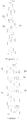
- a low frequency radiation unit 1a and a high frequency radiation unit 2a are coaxially arranged on a same axis 4a of a reflection plate 3a.
- Another solution is side by side adjoining solution as shown in figure 2 .
- a low frequency radiation unit 1b and a high frequency radiation unit 2b are separately disposed on two adjacent axes 4b and 5b of a reflection plate 3b.
- the axial nesting scheme significantly has smaller antenna width and windward area than side by side scheme and accordingly, it gets much favor from clients.
- pitch range of low frequency radiation array is normally from 250mm to 300mm, while pith range of high frequency radiation array is normally from 105mm to 115mm.
- array pitch is selected from above ranges for high and low frequency, when all the high frequency radiation units 2b and low frequency radiation units 1b are coaxial, radiation arms of some low frequency radiation units 1b will locate over the high frequency radiation units 2b, thereby causing severe interference to high frequency radiation units 2b, and greatly increasing difficulty in design of high frequency radiation array radiation characteristics. Attempts have been made to overcome this problem by reducing projection area of the low frequency radiation units 1b. However, this will also increase half-power beam width in horizontal plane of the low frequency radiation units 1b and therefore no desired results may be obtained.
- WO 2010/063007 A2 discloses a high band element and an antenna including a plurality of high band elements.
- the high band element can include directors disposed above four dipoles, and the antenna can include a plurality of low band elements configured to accommodate the plurality of high band elements.
- the low band elements can be configured in a 1 - 2 - 2 - 2 - 1 arrangement or a 2 - 2 - 2 - 2 - 1 arrangement.
- multi-array antennas providing dual electrical azimuth beam steering, combined mechanical and electrical azimuth steering, independent mechanical column steering and dual mechanical steering are described, as well as systems incorporating such antennas and methods of controlling them.
- One object of the invention is to provide a multi-frequency shared antenna capable of maintaining reasonable antenna size and good electric characteristics.
- Another object of the invention is to provide an antenna control system for more suitably using the multi-frequency shared antenna in field.
- a multi-frequency shared antenna comprises a low frequency radiation array and a first high frequency radiation array both of which are disposed on a reflection plate and provided with power by different feeding networks, wherein, the low frequency radiation array comprises a number of low frequency radiation units axially arranged on at least two parallel axes, and said low frequency radiation units on said two axes are misaligned along a direction orthogonal to these axes; the pitch between said two axes of the low frequency radiation array is smaller than or equal to half wavelength of the low frequency radiation array at its highest working frequency point, and greater than or equal to half wavelength of the high frequency radiation array at its highest working frequency point; each low frequency radiation unit comprises two pairs of symmetrical dipoles arranged such that their polarization is orthogonal to each other, and two symmetrical dipoles of one pair of symmetrical dipoles of at least one low frequency radiation unit of the low frequency radiation array have different feed-in power settings; the first high frequency radiation array comprises a number of high frequency radiation units, at least part of the high
- any two adjacent low frequency radiation units arranged on different axes form a group, in four symmetrical dipoles with the same polarization of the group, a symmetrical axis is defined between the first axis and the second axis, symmetrical dipoles close to said symmetrical axis have the same or substantially same feed-in power, symmetrical dipoles away from said symmetrical axis have the same or substantially same feed-in power, and the feed-in power of the dipoles close to the symmetrical axis is greater than that of the dipoles away from the symmetrical axis.
- a symmetrical axis is defined between a first and second axes of two axes occupied by the low frequency radiation array, the sum of feed-in power of the adjacent symmetrical dipoles located at left of the symmetrical axis is identical to or substantially identical to that of the adjacent symmetrical dipoles located at right of the symmetrical axis, the sum of feed-in power of the symmetrical dipoles located at left of the symmetrical axis and distanced away from each other is identical to or substantially identical to that of the symmetrical dipoles located at right of the symmetrical axis and distanced away from each other, and the sum of the former is larger than that of the latter.
- the antenna further comprises a second high frequency radiation array powered by other feeding network, the second high frequency radiation array comprises a number of high frequency radiation units which are at least partially arranged on a same axis, and the axis of the first high frequency radiation array is adjacent and parallel to that of the second high frequency radiation array.
- the axis of the second high frequency radiation array overlaps one axis of the low frequency radiation array, at least part of the high frequency radiation units of the second high frequency radiation array are nested with the low frequency radiation units arranged on the same axis, and the orthogonal projection area of these nested high frequency radiation units on the reflection plate falls within the orthogonal projection area of corresponding low frequency radiation units on the same plate.
- the plural low frequency radiation units of the low frequency radiation array are distributed along said symmetrical axis.
- the antenna further comprises a third and fourth high frequency radiation arrays located parallel to each other and powered by separate feeding networks, an axis of the third high frequency radiation array overlaps an extension line of the axis of the first high frequency radiation array, and an axis of the fourth high frequency radiation array overlaps an extension line of the axis of the second high frequency radiation array, in the ranges of the extension lines where the third and fourth high frequency radiation arrays located, there are low frequency radiation units for nesting with the third and fourth high frequency radiation arrays, the orthogonal projection area of these nested high frequency radiation units on the reflection plate falls within the orthogonal projection area of corresponding low frequency radiation units on the same plate.
- the antenna further comprises a third and fourth high frequency radiation arrays parallel to the first and second high frequency radiation arrays respectively and powered by separate feeding networks, and a second low frequency radiation array powered by separate feeding network, the second low frequency radiation array is assembled with the third and fourth high frequency radiation arrays by the manner aforementioned, and an axis thus formed is parallel to the aforementioned axes.
- part of the high frequency radiation units of the first high frequency radiation array are arranged along another axis; and the high frequency radiation units of the first high frequency radiation array arranged on respective axes are misaligned among each other along a direction orthogonal to the axes.
- both the low frequency radiation array and first high frequency radiation array are distributed on two axes, one axis of the low frequency radiation array overlaps one axis of the first high frequency radiation array, and another axis of the low frequency radiation array and another axis of the first high frequency radiation array are symmetrical about the overlapped axis.
- the pitch between two adjacent axes of the low frequency radiation array is smaller than or equal to the biggest orthogonal projection size of an individual low frequency radiation unit arranged on these axes.
- some low frequency radiation units with odd locations are arranged on an axis of the low frequency radiation array, while some low frequency radiation units with even locations are arranged on another axis thereof.
- some low frequency radiation units with discrete locations are arranged on an axis of the low frequency radiation array, while some low frequency radiation units with continuous locations are arranged on another axis thereof.
- the high frequency radiation units and/or low frequency radiation units are of printed planar radiation unit or surface mounted dipole.
- the biggest diameter of the low frequency radiation unit is smaller than 150mm.
- An antenna control system comprises a multi-frequency shared antenna as described above, and further comprises a phase shifter for changing phase of signal provided to the radiation units inside the antenna, wherein the phase shifter comprises first and second components, and wherein sliding of the first component relative to the second component results in phase change of signal passing through the phase shifter.
- the system comprises an electromechanical driving component; wherein the electromechanical driving component comprises a power control unit, a motor and a mechanical driving unit; wherein in response to an external control signal, the power control unit is configured to drive the motor to produce a predefined motion; and wherein through the torque generated by the mechanical driving unit, the predefined motion of the motor is applied to the first component so as to realize phase shifting.
- the electromechanical driving component comprises a power control unit, a motor and a mechanical driving unit; wherein in response to an external control signal, the power control unit is configured to drive the motor to produce a predefined motion; and wherein through the torque generated by the mechanical driving unit, the predefined motion of the motor is applied to the first component so as to realize phase shifting.
- the present invention has the following good technical advantages.
- the low frequency radiation array is divided into two or more groups distributed on different axis.
- Each group comprises one or more low frequency radiation units.
- One group is disposed to overlap the axis of the high frequency radiation array.
- treble frequency shared antenna including a low frequency radiation array and two high frequency radiation arrays both having the same frequency
- at least part of the high frequency radiation units of the two high frequency radiation arrays are arranged on two substantially parallel axes, and they overlap with one axis of the low frequency radiation array respectively.
- at least part of the high frequency radiation units on each axis are nested with the low frequency radiation units on the same axis. This eliminates gain loss and size increase of the entire antenna due to direct addition of a high frequency radiation array along a vertical direction of the antenna as would be in above coaxial nesting solution.
- the low frequency radiation array is divided into two or more groups distributed on different axis.
- Each group comprises one or more low frequency radiation units.
- One group is disposed to overlap the axis of the high frequency radiation array.
- the number of the low frequency radiation units at one side of the high frequency radiation array is reduced.
- the number of the high frequency radiation units at one side of the low frequency radiation array is also reduced.
- Left and right asymmetry of the low and high frequency radiation arrays is also improved.
- horizontal plane beam direction deflection and cross-polarization ratio are also improved, this further reducing design difficulty.
- the pitch between at least two axes of the low frequency radiation array is regulated. This brings better radiation characteristics such as horizontal plane half power beam width of the multiple-frequency shared antenna. Additionally, the entire lateral size (along orthogonal direction) is just smaller than the lateral size of the low frequency radiation array adjoined the high frequency radiation array, but larger than the lateral size when the low frequency radiation array and high frequency radiation array are nested together.
- horizontal plane half power beam width absolute value is obtained for the low frequency radiation array.
- better horizontal plane half power beam width convergence is also obtained.
- horizontal plane half power beam width is within 62 ⁇ 3 degree. This can't be realized when the low frequency radiation array and high frequency radiation array are nested together or when the low frequency radiation array and high frequency radiation array are adjoined together.
- the present invention is able to realize sharing of multiple frequencies antenna in as small as possible size.
- the pitch between radiation units no longer results in interference between the low and high frequency beams.
- the antenna control system based on this multiple-frequency shared antenna thus also bears all advantages described above.
- This multiple-frequency shared antenna will make it easy and convenient to locate and trim low frequency radiation unit during design period.
- a radiation array (including low frequency and high frequency radiation array) is intended to transmit communication signals and is generally constituted by a plurality of radiation units arranged in matrix in the form of a single or multiple lines.
- a high frequency radiation array is formed by plural high frequency radiation units.
- a low frequency radiation array is formed by plural low frequency radiation units.
- a component for transmitting and receiving signals is a symmetrical dipole of the unit.
- An electrical component of the symmetrical dipole is its radiation arm which is supported by a balun of the symmetrical dipole.
- a radiation unit to improve gain of polarization diversity receiving, two pairs of symmetrical dipoles are employed and they are arranged such that their polarization is orthogonal to each other. Two symmetrical dipoles of each pair of symmetrical dipoles may have different feed-in power setting.
- the radiation unit may be planar and printed on a plate, or it may also be of a three-dimensional construction.
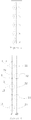
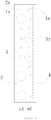
- a multi-frequency shared antenna has a reflection plate 3 onto which a low frequency radiation array 1 and a high frequency radiation array 2 are arranged.
- the low frequency radiation array 1 is composed of 5 low frequency radiation units 11-15.
- these low frequency radiation units 11-15 from top to bottom, 3 low frequency radiation units 11, 13 and 15 (all have odd reference numerals) are located on a first axis a1, while 2 low frequency radiation units 12 and 14 (all have even reference numerals)are located on a second axis a2.
- the first and second axes a1 and a2 are parallel with each other.
- the low frequency radiation units 11-15 located on these axes a1 and a2 respectively are distributed alternately.
- the distance between the first axis a1 and second axis a2 is smaller than or equal to the largest orthogonal projection size of an individual low frequency radiation unit located on these axes a1 and a2.
- the pitch between the first axis a1 and second axis a2 may be configured to be less than or equal to half wavelength of the low frequency radiation array at its highest working frequency point, and at the same time, larger than or equal to half wavelength of the high frequency radiation array at its highest frequency point, thus obtaining balance between antenna size and best electric performance. Normally, if the two axes a1 and a2 meet the former pitch setting, they will also meet the latter pitch setting.
- the high frequency radiation array 2 is composed of 12 high frequency radiation units 2x all of which are disposed at the same axis a1. Of course, this axis a1 is also the first axis a1 of the low frequency radiation array 1.
- the pitch between two adjacent low frequency radiation units is not equal to that between two adjacent high frequency radiation units.
- the pitch between two adjacent high frequency radiation units 2x is constant and the same applies to the two adjacent low frequency radiation units 11-15.
- 3 low frequency radiation units 11, 13 and 15 distributed on odd locations and all high frequency radiation units 12, 14 are arranged commonly on the first axis a1.
- the pitch between two adjacent high frequency radiation units 2x arranged on the first axis a1 is a constant value
- pitch between two adjacent low frequency radiation units 11, 13 and 15 is necessarily integer times of the above constant value.
- each of 3 low frequency radiation units 11, 13 and 15 may be concentrically nested with a corresponding one of 3 high frequency radiation units 21, 22 and 23.
- pitches among them are equal to those of low frequency radiation units 11, 13 and 15 located on the first axis a1.
- the two axes a1 and a2 of the low frequency radiation array 1 may be set to overlap with each other. It can be found that in overlapped low frequency radiation array 1, all low frequency radiation units 11-15 are located with equal pitch. In other words, for these low frequency radiation units 11-15 positioned at different axes a1 and a2, they have definite and same pitch.
- all these nested high frequency radiation units 2x and low frequency radiation units 11-15 are located with their geometrical centers coincide among each other.
- centers of the low frequency radiation units 11, 13 and 15 overlap corresponding centers of high frequency radiation units 21, 22 and 23 and therefore, orthogonal projection area of the radiation arm of each high frequency radiation unit falls within the range of orthogonal projection area of the radiation arm of a corresponding low frequency radiation unit nested with said high frequency radiation unit.
- these orthogonal projection areas neither overlap nor cross among each other.
- the diameter of low frequency radiation unit is normally large. In present invention, it is designed to be less than or equal to 150mm so as to get optimum setting. Accordingly, person of ordinary skill in the art will know that this kind of nesting design may be extended such that orthogonal projection area of the high frequency radiation unit on the reflection plate falls within the orthogonal projection area of the low frequency radiation unit on the reflection plate.
- Each of the low frequency radiation units 11, 13 and 15 on the first axis a1 is nested with a corresponding one of the high frequency radiation units 21, 22 and 23.
- Each of the low frequency radiation units 12 and 14 on the second axis a2 is adjacent to all the high frequency radiation units 2x. Therefore, on the orthogonal projection area of the reflection plate 3, it is avoided that radiation arms (not shown in details, see circles) of the symmetrical dipole of the low frequency radiation units 11-15 will be interfered with radiation arms (not shown in details, see cross line) of the symmetrical dipole of the one or two high frequency radiation units (interfering means overlapping or crossing of the images formed on the orthogonal projection area) . Therefore, signal interference between the low frequency radiation array 1 and high frequency radiation array 2 is reduced mostly, ensuring that signal transmission and receiving of the low frequency radiation array 1 and high frequency radiation array 2 is independent of each other.
- Each low frequency radiation unit includes two pairs of symmetrical dipoles all of which are circularly arranged and symmetrical about a center.
- the low frequency radiation array constructed by said low frequency radiation units 11-15 is located on the first and second axes a1 and a2 respectively. Take a symmetrical axis between the first axis a1 and second axis a2 as a reference line.
- Each of low frequency radiation units 11, 13 and 15 on the first axis a1 has a symmetrical dipole positioned towards the reference line and second axis a2. Another symmetrical dipole is positioned away from the reference line and second axis a2.
- each of low frequency radiation units 12 and 14 on the second axis a2 has a symmetrical dipole positioned towards the reference line and first axis a1. Another symmetrical dipole is positioned away from the reference line and first axis a1. Consequently, symmetrical dipoles located inside of the two axes a1 and a2 are adjacent among each other, while those located outside of the two axes a1 and a2 are distanced among each other.
- the symmetrical dipoles adjacently located have same or substantially same signal feed-in power
- the symmetrical dipoles located outside of the axes also have same or substantially same signal feed-in power.
- the feed-in power of the former is larger than the latter.
- the term "substantially same” means symmetrical dipoles located at two adjacent axes have same signal feed-in power. However, it is noted that physical error is unavoidable. As such, person of ordinary skill in the art will understand that the term “substantially same” also permits adjacent symmetrical dipoles located at two axes have infinitely approximated signal feed-in power. Said means for extending horizontal half power beam width of low frequency radiation array also applies to other embodiments of the invention.
- the low frequency radiation units 11-15 of the low frequency radiation array 1 are arranged to form a temporary array.
- increase or decrease axis pitch between two adjacent temporary arrays such that horizontal plane half power beam width of the entire low frequency radiation array 1 is correspondingly increased or reduced until it is close or equal to said given value.
- the current antenna layout is fixed.
- the high frequency radiation array 2 is equipped with a feeding network (not shown) for supplying power to respective high frequency radiation unit 2x located on the first axis a1 such that the high frequency radiation array 2 is able to radiate high frequency signals.
- the low frequency radiation array 1 is equipped with another feeding network for supplying power to respective low frequency radiation units 11-15 located on the first and second axes a1 and a2 such that the low frequency radiation array 1 is able to radiate low frequency signals.
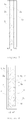
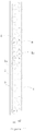
- figure 7 illustrating a second embodiment of the multiple-frequency shared antenna of the invention.
- this embodiment is a dual-frequency shared antenna and the difference of it from the first embodiment lines in 12 high frequency radiation units 2x of the high frequency radiation array 2 are designed to be distributed along two axes a2 and a3.
- the first axis a1 is shared by partial low frequency radiation units 1x and partial high frequency radiation units 2x; the rest high frequency radiation units 2y are separately disposed on the second axis a2; while the rest low frequency radiation units 1y are separately disposed on the third axis a3.
- the second axis a2 and third axis a3 are symmetrical about the first axis a1.
- the high frequency radiation units 2x and 2y have identical axial pitch, and the low frequency radiation units 1x and 1y also have identical axial pitch.
- two high frequency radiation units 2y corresponding along an orthogonal direction to each low frequency radiation unit 1x (there are 2 units 1x and accordingly there are 4 units 2y) arranged on the third axis a3 are biased away from the first axis a1 and disposed on the second axis a2, thus forming layout as shown in figure 7 .
- the improvement of this embodiment has effect similar to the first embodiment. However, this embodiment achieves more even and symmetrical physical construction. Compared to the first one, this embodiment further reduces horizontal size.
- the low and high frequency radiation units work on different frequency range.
- “low frequency” as occurred in low frequency radiation unit is relative to the "high frequency” as used in high frequency radiation unit.
- the low frequency radiation units work on frequency range of 790-960MHz covering 2G and 3G mobile communication frequency bands currently used all over the world, while high frequency radiation units work on frequency range of 1700-2700MHz covering 4 G mobile communication frequency band such as LTE currently used all over the world.
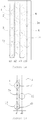
- a treble-frequency shared antenna is disclosed.
- a second high frequency radiation array 4 is added.
- the second high frequency radiation array 4 is provided with power by another feeding network different from the first high frequency radiation array 2.
- the second high frequency radiation array 4 also includes 12 high frequency radiation units 4x arranged along a same axis. From figure 8 it can be seen that the axis a2 of the second high frequency radiation array 4 is parallel to the axis a1 of the first high frequency radiation array 2 and overlaps with the second axis a2 of the first low frequency radiation array 1.
- the second high frequency radiation array 4 is parallel to the first high frequency radiation array 2.
- start location of the second high frequency radiation array 4 on the second axis a2 is adjusted so that the orthogonal projection of the two high frequency radiation units 41, 42 on the reflection plane 3 and that of the two low frequency radiation units 12, 14 of the low frequency radiation array 1 on the second axis a2 have the same geometrical center (nesting relationship as described in the first embodiment)
- the first high frequency radiation array 2 and second high frequency radiation array 4 will be misaligned in vertical direction. This layout will not have influence on its electric performance. Therefore, this embodiment is also able to realize normal signal operation at 3 frequency bands. This ensures that antenna size is minimized and also ensures that interference among radiation arrays working different frequency bands is mostly reduced.
- a fourth embodiment of a multi-frequency shared antenna of the present invention is made upon prior art technique shown in figure 5 .
- the difference between this embodiment and the third embodiment lies in the pitch between low frequency radiation units is integer times as great as the pitch between high frequency radiation units.
- the pitch between low frequency radiation units is not integer times as great as the pitch between high frequency radiation units.
- the first and second high frequency radiation units 2x and 4x are aligned with each other, thus regularly forming two columns of matrices.
- each of the first and second high frequency radiation arrays 2 and 4 only includes 10 high frequency radiation units 2x and 4x, while the low frequency radiation array 1 still maintains its 5 low frequency radiation units 1x, 1y. Accordingly, the pitch between two adjacent low frequency radiation units arranged on each axis is still integer times as great as the pitch between two adjacent high frequency radiation units 2x, 4x of each of the high frequency radiation arrays 2 and 4.
- the low frequency radiation units 1x are provided on the first axis a1 on which the low frequency radiation array 1 is located (that is, the axis on which the first high frequency radiation array 2 locates), 3 low frequency radiation units 1x are provided, while on the second axis a2 on which the low frequency radiation array 1 is located (that is, the axis on which the second high frequency radiation array 4 locates), 2 low frequency radiation units 1y are provided.
- Each of the low frequency radiation units 1x and 1y are nested with a corresponding high frequency radiation in the aforementioned manner.
- the axes a1 and a2 there is just a location for one high frequency radiation unit between two low frequency radiation units.
- a low frequency radiation unit nested with another high frequency radiation unit adjacent to a first high frequency radiation unit is provided.
- 3 low frequency radiation units 1x is arranged on the first axis a1 at locations 1, 4 and 5 in order, while 2 adjacent low frequency radiation units 1y is arranged on the second axis a2 at locations 2 and 3 in order.
- the Multi-frequency shared antenna realized in this embodiment may also realize normal signal operation at 3 frequency bands. This ensures that antenna size is minimized and also ensures that interference among radiation arrays working at different frequency bands is mostly reduced.
- the fifth embodiment of the multi-frequency shared antenna of the invention is made upon the third embodiment.
- a number of low frequency radiation units 1z of the low frequency radiation array 1 are added on an extending direction of the respective axes a1 and a2.
- 5 low frequency radiation units 1z are disposed above the first and second high frequency radiation arrays 2 and 4.
- 4 of these low frequency radiation units 1z are located on a third axis a3 which is just a symmetrical axis of the first axis a1 and second axis a2 of the low frequency radiation array 1 as stated in the third embodiment.
- the third axis a3 is also the symmetrical axis of the axes of the first and second high frequency radiation arrays 2 and 4.
- the rest one of the 5 low frequency radiation units 1z is directly positioned on the axis a2 of the second high frequency radiation array 4 (it is also the second axis a2 of the low frequency radiation array 1).
- 3 low frequency radiation units are arranged on the second axis a2 of the low frequency radiation array 1.
- 2 low frequency radiation units 1y fall within axis range occupied by 4 high frequency radiation units 4y of the second high frequency radiation array 4, and are nested with these high frequency radiation units by the manner described in aforementioned embodiments.
- the rest one low frequency radiation unit is located outside of the second high frequency radiation array 4.
- pitch between each two adjacent low frequency radiation units along the axes a1 and a2 is identical. Consequently, this embodiment may also obtain technical effects obtained by preceding embodiments.
- a sixth embodiment of a multi-frequency shared antenna of the invention discloses a five-frequency shared antenna made upon the third embodiment.
- this kind of multi-frequency shared antenna further comprises a third and fourth high frequency radiation arrays 6 and 8 powered by separate two feeding networks respectively.
- the axis a1 of the third high frequency radiation array 6 overlaps the extension line of the axis a1 of the first high frequency radiation array 2, whilst the axis a2 of the fourth high frequency radiation array 2 overlaps the extension line of the axis a2 of the second high frequency radiation array 2.
- Partial low frequency radiation units 1x and 1y of the low frequency radiation array 1 are located on the extension lines of the first and second axes a1 and a2 respectively. Therefore, the total number of the low frequency radiation units 1x and 1y of the low frequency radiation array 1 is increased to 10 and these low frequency radiation units constitute an array and are powered by a same feeding network. Considering number and location relationship of the low frequency radiation units 1x distributed on the first axis a1 and resultant electrical relationship, when the number of the low frequency radiation units 1x within the axis range occupied by the first high frequency radiation array 2 is 3, the number of the low frequency radiation units 1x within the axis range occupied by the third high frequency radiation array 6 will be 2.
- each low frequency radiation array 1 is nested with 4 high frequency radiation arrays 2, 4, 6 and 8 and all these arrays are mounted on the same reflection plate 3. As a result, the antenna size is significantly reduced and electric performance is still good.
- a seventh embodiment of a multi-frequency shared antenna of the invention discloses a six-frequency shared antenna based on the third embodiment. However, this embodiment is different from the third embodiment in their layout. In the seventh embodiment, it is formed with side by side arrangement of the antennae illustrated in the third embodiment. Specifically, it includes a third and fourth high frequency radiation arrays 6 and 8 parallel to the first and second high frequency radiation arrays 2 and 4 and powered separately by other feeding networks. In addition, it also includes two low frequency radiation arrays.
- the low frequency radiation units 1x, 1y, 1z and 1w are distributed on at least four axes a1, a2, a3 and a4 overlapping the axes a1, a2, a3 and a4 of the second high frequency radiation array 2 respectively.
- the low frequency radiation units 1x and 1y form a low frequency radiation array working at an independent frequency band and are powered by a separate feeding network.
- the low frequency radiation units 1z and 1w form another low frequency radiation array working at an independent frequency band and are powered by another feeding network.
- this embodiment may also realize small antenna size and get better electric performance.
- the multi-frequency shared antenna of the invention may find its application in an antenna control system.
- multiple high frequency radiation arrays 2 and low frequency radiation arrays 1 are powered by different feeding networks.
- Each feeding network contains a phase shifter including first and second components. Sliding of the first component relative to the second component results in phase change of signal passing through the phase shifter, thereby changing phase of the signal provided to corresponding radiation unit and resulting in tilting of the antenna beam.
- driving force is supplied to the first component of the phase shifter so as to realize remote control of the antenna beam tilting.
- the antenna control system is provided with a removable electromechanical driving component.
- the electromechanical driving component includes a power control unit, a motor and a mechanical driving unit.
- the power control unit drives the motor to produce a predefined motion.
- the predefined motion of the motor is applied to the first component so as to realize phase shifting.
- the electromechanical driving component may be installed in the multi-frequency shared antenna and the mechanical driving unit thereof may act on the first component of the phase shift, thus achieving beam down-tilting adjustment by external signal control.
- the electromechanical driving component may be turned off therefrom such that respective phase shifters of each feeding networks are maintained phase stationary. By this manner, beam tilting angle of the multi-frequency shared antenna is constant.
- an axis as used herein means a hypothetical line segment.
- overlapping between the axes also permits slight deviation as known by person of skill in the art.
- an axis may be bias a slight distance from the another axis.
- the axis of the high frequency radiation array may also be biased a distance from the axis of the low frequency radiation array if the low frequency radiation units are designed to be of bowl-shaped balun. Accordingly, slight deviation between two axes is also within the meaning of the term "overlapping" as defined in this invention.
- the same reasoning also applies to the term "concentric".
- the low frequency radiation unit may be a symmetric dipole which has an orthogonal projection shape on the reflection plate of diamond, rectangular, polygon or multiple segments. It may also be a surface mounted dipole or flatly printed radiation unit.
- the high frequency radiation unit may be dipole disclosed in US Patent No.: 6933906B2 to Kathrein , Chinese Patent No.: CN2702458Y to Comba Company or US Patent No.: US7053852B2 to Adrew or other type of dipole.
- the biggest diameter of the low frequency radiation unit is smaller than 150mm so as to further reduce size of the antenna and ensure good electric performance.
- an embodiment of the invention also provides a multi-frequency antenna including a reflection plate 3, a first frequency radiation array 2x (including 21 and 23) and a second frequency radiation array (11, 12 and 13).
- the first frequency is higher than the second frequency.
- the second frequency radiation array (11, 12 and 13) has a first axis a1 and a second axis a2 substantially parallel in a vertical direction to the first axis a1. It is understood that the axes a1 and a2 are hypothetical to further illustrate relationship between the first frequency radiation array and second frequency radiation array on the reflection plate 3.
- the second frequency radiation array includes at least three second frequency radiation units (11, 12 and 13) located on the first and second axes a1 and a2 respectively. At least one second frequency radiation unit is provided on each axis.
- the three second frequency radiation units (11, 12 and 13) are misaligned among each other in a direction orthogonal to the axial direction.
- three second frequency radiation units (11, 12 and 13) have the same or similar distance among each other in a direction orthogonal to the axial direction.
- the first frequency radiation array includes at least one first frequency radiation unit 21 located on the first axis a1.
- the second frequency radiation units (11 and 13) on the first axis a1 are nested with partial first frequency radiation units (21 and 23) on the first axis a1.
- the nesting may be realized as follows: the orthogonal projection area of the first frequency radiation unit on the reflection plate falls within the orthogonal projection area of the second frequency radiation unit on the same plate.
- the antenna has reasonable size and better electric performance as well.
- each second frequency radiation unit includes two polarization elements each of which includes two radiation arms. Said two radiation arms may be provided with different power. Further, each radiation arm is a symmetrical dipole. Each polarization element of the second frequency radiation unit has a pair of symmetrical dipoles which can be supplied with different feed-in power. Using different feed-in power, the horizontal plane half power beam width of the second frequency radiation array is regulated.
- the symmetrical dipoles described in this embodiment may be those disclosed in US Patents 4434425 , US6333720 , or Chinese Patent 200710031144.3 .
- the first frequency radiation array 2x (including 21 and 23) and second frequency radiation array (11, 12 and 13) positioned on the reflection plate 3 are powered by different feeding networks.
- the pitch between the first and second axes is smaller than or equal to the biggest orthogonal projection size of a single second frequency radiation unit arranged on one of two axes.
- the biggest orthogonal projection size means the longest distance between two sides of the projection perimeter of the radiation unit projected onto the reflection plate.
- the biggest orthogonal projection size is the diameter of the circle; and for a square projection, the biggest orthogonal projection size is the length of the diagonal line.
- the biggest orthogonal projection size is the smallest diameter of a circle which encircles the irregular projection shape. Therefore, the present invention is adapted to specific used frequency requirement.
- a symmetrical axis a3 is defined between the first and second axes.
- Two low frequency radiation units of all the second frequency radiation units positioned on different axes form a group.
- symmetrical dipoles close to the symmetrical axis a3 have the same or similar feed-in power, and those away from the symmetrical axis a3 also have the same or similar feed-in power.
- feed-in power of those dipoles close to the symmetrical axis a3 is greater than that of the dipoles away from the symmetrical axis a3.
- the second frequency radiation has its geometrical center overlapped that of at least one first frequency radiation unit.
- nesting use of the second frequency radiation unit on the first axis and partial first frequency radiation units on the same axis is as follows: the orthogonal projection area of the high frequency radiation unit on the reflection plate falls within that of the low frequency radiation unit on the same plate.
- the second frequency radiation array also includes a third axis running as a symmetrical axis of the first and second axes.
- the second low frequency radiation units are located on this symmetrical axis.
- the antenna is benefited from reasonable size, and better electric performance. Further, relationship between linear arrangement pitch of the low frequency radiation units and that of the high frequency radiation units is no longer a critical factor having heavy influence on design of antenna layout by person of skill in the art.
- the antenna size is more reasonable because of the following reasons.
- pitch among low frequency radiation units arranged on the same axis is integer times as great as that of the high frequency radiation units, for example in case where three frequencies present and at least two of them are identical high frequency arrays, compared to solution in which a group of high frequency radiation arrays is added in a vertical direction of the antenna, use of the present invention not only avoids increase of transfer loss caused by lengthening of the main feeder line of the upper high frequency radiation arrays, but also obtain increase of antenna gain. Moreover, when the length of the low frequency radiation array is smaller than integer times of the length of the high frequency radiation array, the entire length of the antenna is dramatically decreased. Compared to adjoining technical solution, use of the invention also reduces width of the antenna. Further, as the low frequency radiation units are arranged in a misaligned manner in a direction orthogonal to the axis, symmetry between left and right radiation boundary of the low and high frequency radiation arrays is improved. Antenna design difficulty is also reduced.
Landscapes
- Physics & Mathematics (AREA)
- Electromagnetism (AREA)
- Variable-Direction Aerials And Aerial Arrays (AREA)
- Transducers For Ultrasonic Waves (AREA)
Applications Claiming Priority (2)
| Application Number | Priority Date | Filing Date | Title |
|---|---|---|---|
| CN201210012047 | 2012-01-13 | ||
| PCT/CN2012/087783 WO2013104260A1 (zh) | 2012-01-13 | 2012-12-28 | 天线控制系统和多频共用天线 |
Publications (3)
| Publication Number | Publication Date |
|---|---|
| EP2804260A1 EP2804260A1 (en) | 2014-11-19 |
| EP2804260A4 EP2804260A4 (en) | 2015-09-30 |
| EP2804260B1 true EP2804260B1 (en) | 2018-03-21 |
Family
ID=48207022
Family Applications (1)
| Application Number | Title | Priority Date | Filing Date |
|---|---|---|---|
| EP12865113.0A Active EP2804260B1 (en) | 2012-01-13 | 2012-12-28 | Aerial control system and multi-frequency common aerial |
Country Status (8)
| Country | Link |
|---|---|
| US (1) | US9559432B2 (zh) |
| EP (1) | EP2804260B1 (zh) |
| CN (2) | CN104221218B (zh) |
| BR (1) | BR112014017345A2 (zh) |
| ES (1) | ES2673127T3 (zh) |
| IN (1) | IN2014DN06478A (zh) |
| TR (1) | TR201808848T4 (zh) |
| WO (1) | WO2013104260A1 (zh) |
Families Citing this family (38)
| Publication number | Priority date | Publication date | Assignee | Title |
|---|---|---|---|---|
| FR2985099B1 (fr) * | 2011-12-23 | 2014-01-17 | Alcatel Lucent | Antenne panneau multibande a polarisation croisee |
| US9559432B2 (en) * | 2012-01-13 | 2017-01-31 | Comba Telecom System (China) Ltd. | Antenna control system and multi-frequency shared antenna |
| CN103560337B (zh) * | 2013-10-25 | 2016-03-09 | 广东博纬通信科技有限公司 | 一种多频段阵列天线 |
| CN203813033U (zh) | 2013-12-23 | 2014-09-03 | 华为技术有限公司 | 一种多频阵列天线 |
| CN103715522B (zh) * | 2014-01-20 | 2016-09-14 | 武汉虹信通信技术有限责任公司 | 一种支持多制式的多天线阵列 |
| EP3188311A4 (en) * | 2014-10-24 | 2017-09-06 | Huawei Technologies Co. Ltd. | Antenna system and processing method |
| US9923591B2 (en) * | 2014-11-12 | 2018-03-20 | Sony Corporation | Array antennas including non-uniform antenna elements |
| CN104466362A (zh) * | 2014-12-12 | 2015-03-25 | 浙江佳源通讯技术有限公司 | 一种高增益多频段高铁覆盖板状天线 |
| CN106207398B (zh) * | 2015-04-30 | 2023-08-25 | 上海诺基亚贝尔股份有限公司 | 一种双宽频交叉极化的天线平台 |
| CN105305098B (zh) * | 2015-09-29 | 2018-05-18 | 电子科技大学 | 基于强互耦效应的超宽带共孔径相控阵天线及研制方法 |
| CN205319307U (zh) | 2015-12-16 | 2016-06-15 | 华为技术有限公司 | 平面阵列天线及通信设备 |
| CN106207490B (zh) * | 2016-08-18 | 2021-06-25 | 京信通信技术(广州)有限公司 | 多系统共体天线 |
| CN106129601A (zh) * | 2016-08-31 | 2016-11-16 | 广东通宇通讯股份有限公司 | 基站天线 |
| CN112768954A (zh) * | 2016-09-19 | 2021-05-07 | 华为技术有限公司 | 一种天线以及网络设备 |
| CN106252903A (zh) * | 2016-09-29 | 2016-12-21 | 广东博纬通信科技有限公司 | 一种双频两波束天线阵列及双频两波束天线 |
| CN106410396A (zh) * | 2016-10-26 | 2017-02-15 | 华南理工大学 | 一种高低频滤波阵子交织排列的紧凑型多波束天线阵列 |
| CN108258436B (zh) * | 2016-12-28 | 2022-02-18 | 中国移动通信集团公司 | 一种天线及通信终端 |
| DE102017001543A1 (de) | 2017-02-16 | 2018-08-16 | Kathrein-Werke Kg | Antenne, insbesondere Mobilfunkantenne |
| CN107154537A (zh) * | 2017-06-20 | 2017-09-12 | 江苏华灿电讯股份有限公司 | 一种八端口双频双极化电调天线 |
| CN107359424B (zh) * | 2017-07-03 | 2023-08-01 | 广东博纬通信科技有限公司 | 一种阵列天线 |
| EP3656017A1 (en) | 2017-08-04 | 2020-05-27 | Huawei Technologies Co., Ltd. | Multiband antenna |
| EP3460905B8 (en) * | 2017-09-21 | 2022-06-22 | Nokia Shanghai Bell Co., Ltd. | Multiple band antenna |
| CN107516769A (zh) * | 2017-09-28 | 2017-12-26 | 中国联合网络通信集团有限公司 | 辐射方向图可重构的天线 |
| CN107959125B (zh) * | 2017-11-17 | 2020-10-20 | 深圳市盛路物联通讯技术有限公司 | 阵列天线及无线通信设备 |
| CN108232466A (zh) * | 2018-01-09 | 2018-06-29 | 广东博纬通信科技有限公司 | 一种混合多波束天线 |
| CN110061341A (zh) * | 2018-01-19 | 2019-07-26 | 中国联合网络通信集团有限公司 | 一种铁路覆盖方法、宽波束高增益天线及多频段共用天线 |
| US11283195B2 (en) * | 2018-01-24 | 2022-03-22 | John Mezzalingua Associates, LLC | Fast rolloff antenna array face with heterogeneous antenna arrangement |
| CN110071373B (zh) * | 2018-03-12 | 2023-03-14 | 京信通信技术(广州)有限公司 | 多制式融合的天线 |
| US11101562B2 (en) | 2018-06-13 | 2021-08-24 | Mediatek Inc. | Multi-band dual-polarized antenna structure and wireless communication device using the same |
| CN109301459B (zh) * | 2018-10-29 | 2023-10-03 | 京信通信技术(广州)有限公司 | 多频阵列天线 |
| CN111786081A (zh) * | 2019-04-04 | 2020-10-16 | 康普技术有限责任公司 | 具有集成阵列的多频带基站天线 |
| CN110265795B (zh) * | 2019-07-02 | 2024-02-27 | 京信通信技术(广州)有限公司 | 多频窄波束天线 |
| CN110492254B (zh) * | 2019-08-09 | 2024-02-23 | 摩比科技(深圳)有限公司 | 多频天线阵列 |
| CN110970712B (zh) * | 2019-12-11 | 2024-04-26 | 京信通信技术(广州)有限公司 | 多频合路天线 |
| CN110829003A (zh) * | 2019-12-18 | 2020-02-21 | 广东博纬通信科技有限公司 | 一种窄截面多系统阵列天线 |
| CN111969334A (zh) * | 2020-08-12 | 2020-11-20 | 京信通信技术(广州)有限公司 | 多频阵列天线及基站 |
| CN112397885A (zh) * | 2020-10-28 | 2021-02-23 | 广东盛路通信科技股份有限公司 | 高低频阵列天线 |
| CN112821082B (zh) * | 2021-01-04 | 2022-04-19 | 武汉虹信科技发展有限责任公司 | 水平波瓣宽度可调的天线及基站 |
Family Cites Families (28)
| Publication number | Priority date | Publication date | Assignee | Title |
|---|---|---|---|---|
| US4434425A (en) | 1982-02-02 | 1984-02-28 | Gte Products Corporation | Multiple ring dipole array |
| DE19823749C2 (de) * | 1998-05-27 | 2002-07-11 | Kathrein Werke Kg | Dualpolarisierte Mehrbereichsantenne |
| US6211841B1 (en) * | 1999-12-28 | 2001-04-03 | Nortel Networks Limited | Multi-band cellular basestation antenna |
| EP1380069B1 (en) * | 2001-04-16 | 2007-06-06 | Fractus, S.A. | Dual-band dual-polarized antenna array |
| US7639196B2 (en) * | 2001-07-10 | 2009-12-29 | Andrew Llc | Cellular antenna and systems and methods therefor |
| DE10256960B3 (de) * | 2002-12-05 | 2004-07-29 | Kathrein-Werke Kg | Zweidimensionales Antennen-Array |
| WO2004055938A2 (en) * | 2002-12-13 | 2004-07-01 | Andrew Corporation | Improvements relating to dipole antennas and coaxial to microstrip transitions |
| DE50307071D1 (de) * | 2002-12-23 | 2007-05-31 | Huber+Suhner Ag | Breitband-Antenne mit einem 3-dimensionalen Gussteil |
| DE10316564B4 (de) * | 2003-04-10 | 2006-03-09 | Kathrein-Werke Kg | Antenne mit zumindest einem Dipol oder einer dipolähnlichen Strahleranordnung |
| US7817096B2 (en) * | 2003-06-16 | 2010-10-19 | Andrew Llc | Cellular antenna and systems and methods therefor |
| FR2863111B1 (fr) * | 2003-12-01 | 2006-04-14 | Jacquelot | Antenne en reseau multi-bande a double polarisation |
| CN2702458Y (zh) | 2003-12-26 | 2005-05-25 | 京信通信系统(广州)有限公司 | 一种双极化宽频段天线辐射单元 |
| US7053852B2 (en) | 2004-05-12 | 2006-05-30 | Andrew Corporation | Crossed dipole antenna element |
| US20070008236A1 (en) * | 2005-07-06 | 2007-01-11 | Ems Technologies, Inc. | Compact dual-band antenna system |
| EP1908147B1 (en) * | 2005-07-22 | 2015-08-19 | Powerwave Technologies Sweden AB | Antenna arrangement with interleaved antenna elements |
| CN2831460Y (zh) * | 2005-08-04 | 2006-10-25 | 中山市通宇通讯设备有限公司 | 一种移相器 |
| CN2845198Y (zh) * | 2005-09-14 | 2006-12-06 | 摩比天线技术(深圳)有限公司 | 双频双极化天线 |
| EP1935057B1 (en) * | 2005-10-14 | 2012-02-01 | Fractus S.A. | Slim triple band antenna array for cellular base stations |
| CN100589278C (zh) * | 2005-11-16 | 2010-02-10 | 京信通信技术(广州)有限公司 | 宽带工字型单极化振子 |
| CN101425626B (zh) * | 2007-10-30 | 2013-10-16 | 京信通信系统(中国)有限公司 | 宽频带环状双极化辐射单元及线阵天线 |
| DE102007060083A1 (de) * | 2007-12-13 | 2009-06-18 | Kathrein-Werke Kg | Mehrspalten-Multiband-Antennen-Array |
| WO2010063007A2 (en) * | 2008-11-26 | 2010-06-03 | Andrew Llc | Dual band base station antenna |
| CN101505008B (zh) * | 2009-03-24 | 2012-11-28 | 江苏华灿电讯股份有限公司 | 一种能覆盖三个频段的双极化宽频带阵列智能天线 |
| CN201508910U (zh) * | 2009-08-12 | 2010-06-16 | 江苏捷士通科技股份有限公司 | 双极化三频段基站天线 |
| CN102157780B (zh) * | 2011-01-30 | 2015-03-11 | 广东通宇通讯股份有限公司 | 一种多制式天线 |
| CN102299398B (zh) * | 2011-05-20 | 2013-12-25 | 广东通宇通讯股份有限公司 | 一种双频双极化天线 |
| US9559432B2 (en) * | 2012-01-13 | 2017-01-31 | Comba Telecom System (China) Ltd. | Antenna control system and multi-frequency shared antenna |
| CN102832455A (zh) * | 2012-08-31 | 2012-12-19 | 华为技术有限公司 | 天线阵列和天线装置 |
-
2012
- 2012-12-28 US US14/371,369 patent/US9559432B2/en active Active
- 2012-12-28 TR TR2018/08848T patent/TR201808848T4/tr unknown
- 2012-12-28 IN IN6478DEN2014 patent/IN2014DN06478A/en unknown
- 2012-12-28 BR BR112014017345A patent/BR112014017345A2/pt active Search and Examination
- 2012-12-28 CN CN201280065830.1A patent/CN104221218B/zh active Active
- 2012-12-28 EP EP12865113.0A patent/EP2804260B1/en active Active
- 2012-12-28 WO PCT/CN2012/087783 patent/WO2013104260A1/zh active Application Filing
- 2012-12-28 ES ES12865113.0T patent/ES2673127T3/es active Active
-
2013
- 2013-01-11 CN CN201310012058.3A patent/CN103094715B/zh active Active
Non-Patent Citations (1)
| Title |
|---|
| None * |
Also Published As
| Publication number | Publication date |
|---|---|
| ES2673127T8 (es) | 2018-10-22 |
| US9559432B2 (en) | 2017-01-31 |
| CN103094715A (zh) | 2013-05-08 |
| EP2804260A4 (en) | 2015-09-30 |
| WO2013104260A1 (zh) | 2013-07-18 |
| CN103094715B (zh) | 2018-09-07 |
| CN104221218B (zh) | 2017-03-29 |
| TR201808848T4 (tr) | 2018-07-23 |
| BR112014017345A2 (pt) | 2017-06-27 |
| EP2804260A1 (en) | 2014-11-19 |
| ES2673127T3 (es) | 2018-06-19 |
| IN2014DN06478A (zh) | 2015-06-12 |
| US20150009078A1 (en) | 2015-01-08 |
| CN104221218A (zh) | 2014-12-17 |
Similar Documents
| Publication | Publication Date | Title |
|---|---|---|
| EP2804260B1 (en) | Aerial control system and multi-frequency common aerial | |
| EP2214260B1 (en) | Broadband annular dual-polarization radiation element and line shape antenna array | |
| US11309629B2 (en) | Multiplexed antennas that sector-split in a first band and operate as MIMO antennas in a second band | |
| US6943732B2 (en) | Two-dimensional antenna array | |
| EP2710668B1 (en) | Tri-pole antenna element and antenna array | |
| KR101308514B1 (ko) | 종방향 또는 횡방향 웨브를 구비하는 이중 편파 안테나 | |
| US11108137B2 (en) | Compact omnidirectional antennas having stacked reflector structures | |
| TWI628861B (zh) | 複合天線 | |
| KR101672502B1 (ko) | 이중 편파 무지향성 안테나 | |
| CN109923736B (zh) | 具有方位角波束宽度稳定化的透镜基站天线 | |
| WO2012126439A2 (zh) | 天线阵列、天线装置和基站 | |
| US20180145400A1 (en) | Antenna | |
| EP2951887A1 (en) | An antenna arrangement and a base station | |
| CN112242603A (zh) | 具有多频带波束形成器阵列的基站天线和相关操作方法 | |
| WO2020171976A1 (en) | Base station antennas having arrays of radiating elements with 4 ports without usage of diplexers | |
| CA2506198C (en) | Two-dimensional antenna array | |
| EP2564469B1 (en) | Planar array antenna with reduced beamwidth | |
| US11909102B2 (en) | Base station antennas having partially-shared wideband beamforming arrays | |
| CN112133999A (zh) | 基站天线 | |
| WO2017090200A1 (ja) | アンテナ装置 | |
| US20230006367A1 (en) | BASE STATION ANTENNAS INCLUDING SLANT +/- 45º AND H/V CROSS-DIPOLE RADIATING ELEMENTS THAT OPERATE IN THE SAME FREQUENCY BAND | |
| US11283195B2 (en) | Fast rolloff antenna array face with heterogeneous antenna arrangement | |
| CN209766628U (zh) | 基站天线 | |
| CN107611597B (zh) | 具有赋形波束且可作为阵元的低剖强耦合子阵及设计方法 | |
| CN101359772A (zh) | 双环辐射单元和平板天线 |
Legal Events
| Date | Code | Title | Description |
|---|---|---|---|
| PUAI | Public reference made under article 153(3) epc to a published international application that has entered the european phase |
Free format text: ORIGINAL CODE: 0009012 |
|
| 17P | Request for examination filed |
Effective date: 20140812 |
|
| AK | Designated contracting states |
Kind code of ref document: A1 Designated state(s): AL AT BE BG CH CY CZ DE DK EE ES FI FR GB GR HR HU IE IS IT LI LT LU LV MC MK MT NL NO PL PT RO RS SE SI SK SM TR |
|
| DAX | Request for extension of the european patent (deleted) | ||
| RA4 | Supplementary search report drawn up and despatched (corrected) |
Effective date: 20150831 |
|
| RIC1 | Information provided on ipc code assigned before grant |
Ipc: H01Q 5/42 20150101ALI20150825BHEP Ipc: H01Q 21/26 20060101ALI20150825BHEP Ipc: H01Q 19/10 20060101ALN20150825BHEP Ipc: H01Q 5/307 20150101ALN20150825BHEP Ipc: H01Q 21/06 20060101ALI20150825BHEP Ipc: H01Q 21/00 20060101ALI20150825BHEP Ipc: H01Q 21/24 20060101AFI20150825BHEP |
|
| GRAP | Despatch of communication of intention to grant a patent |
Free format text: ORIGINAL CODE: EPIDOSNIGR1 |
|
| RIC1 | Information provided on ipc code assigned before grant |
Ipc: H01Q 5/307 20150101ALN20171103BHEP Ipc: H01Q 21/06 20060101ALI20171103BHEP Ipc: H01Q 21/26 20060101ALI20171103BHEP Ipc: H01Q 19/10 20060101ALN20171103BHEP Ipc: H01Q 21/00 20060101ALI20171103BHEP Ipc: H01Q 21/24 20060101AFI20171103BHEP Ipc: H01Q 5/42 20150101ALI20171103BHEP |
|
| INTG | Intention to grant announced |
Effective date: 20171205 |
|
| GRAS | Grant fee paid |
Free format text: ORIGINAL CODE: EPIDOSNIGR3 |
|
| GRAA | (expected) grant |
Free format text: ORIGINAL CODE: 0009210 |
|
| AK | Designated contracting states |
Kind code of ref document: B1 Designated state(s): AL AT BE BG CH CY CZ DE DK EE ES FI FR GB GR HR HU IE IS IT LI LT LU LV MC MK MT NL NO PL PT RO RS SE SI SK SM TR |
|
| REG | Reference to a national code |
Ref country code: GB Ref legal event code: FG4D |
|
| REG | Reference to a national code |
Ref country code: CH Ref legal event code: EP |
|
| REG | Reference to a national code |
Ref country code: AT Ref legal event code: REF Ref document number: 982034 Country of ref document: AT Kind code of ref document: T Effective date: 20180415 |
|
| REG | Reference to a national code |
Ref country code: IE Ref legal event code: FG4D |
|
| REG | Reference to a national code |
Ref country code: DE Ref legal event code: R096 Ref document number: 602012044351 Country of ref document: DE |
|
| REG | Reference to a national code |
Ref country code: ES Ref legal event code: FG2A Ref document number: 2673127 Country of ref document: ES Kind code of ref document: T3 Effective date: 20180619 |
|
| REG | Reference to a national code |
Ref country code: SE Ref legal event code: TRGR |
|
| RAP2 | Party data changed (patent owner data changed or rights of a patent transferred) |
Owner name: COMBA TELECOM SYSTEM (CHINA) LTD. |
|
| REG | Reference to a national code |
Ref country code: NL Ref legal event code: MP Effective date: 20180321 |
|
| RIN2 | Information on inventor provided after grant (corrected) |
Inventor name: LIU, PEITAO Inventor name: JIA, FEIFEI Inventor name: SUN, SHANQIU Inventor name: BINLONG, BU Inventor name: QIANG, WANG |
|
| REG | Reference to a national code |
Ref country code: DE Ref legal event code: R081 Ref document number: 602012044351 Country of ref document: DE Owner name: COMBA TELECOM TECHNOLOGY (GUANGZHOU) LTD., GUA, CN Free format text: FORMER OWNERS: COMBA TELECOM SYSTEM (CHINA) LTD., GUANGZHOU, GUANGDONG, CN; JIA, FEIFEI, GUANGZHOU, GUANGDONG, CN; LIU, PEITAO, GUANGZHOU, GUANGDONG, CN; SUN, SHANQIU, GUANGZHOU, GUANGDONG, CN Ref country code: DE Ref legal event code: R081 Ref document number: 602012044351 Country of ref document: DE Owner name: COMBA TELECOM SYSTEM (CHINA) LTD., GUANGZHOU, CN Free format text: FORMER OWNERS: COMBA TELECOM SYSTEM (CHINA) LTD., GUANGZHOU, GUANGDONG, CN; JIA, FEIFEI, GUANGZHOU, GUANGDONG, CN; LIU, PEITAO, GUANGZHOU, GUANGDONG, CN; SUN, SHANQIU, GUANGZHOU, GUANGDONG, CN |
|
| PG25 | Lapsed in a contracting state [announced via postgrant information from national office to epo] |
Ref country code: HR Free format text: LAPSE BECAUSE OF FAILURE TO SUBMIT A TRANSLATION OF THE DESCRIPTION OR TO PAY THE FEE WITHIN THE PRESCRIBED TIME-LIMIT Effective date: 20180321 Ref country code: CY Free format text: LAPSE BECAUSE OF FAILURE TO SUBMIT A TRANSLATION OF THE DESCRIPTION OR TO PAY THE FEE WITHIN THE PRESCRIBED TIME-LIMIT Effective date: 20180321 Ref country code: FI Free format text: LAPSE BECAUSE OF FAILURE TO SUBMIT A TRANSLATION OF THE DESCRIPTION OR TO PAY THE FEE WITHIN THE PRESCRIBED TIME-LIMIT Effective date: 20180321 Ref country code: LT Free format text: LAPSE BECAUSE OF FAILURE TO SUBMIT A TRANSLATION OF THE DESCRIPTION OR TO PAY THE FEE WITHIN THE PRESCRIBED TIME-LIMIT Effective date: 20180321 |
|
| REG | Reference to a national code |
Ref country code: LT Ref legal event code: MG4D |
|
| REG | Reference to a national code |
Ref country code: AT Ref legal event code: MK05 Ref document number: 982034 Country of ref document: AT Kind code of ref document: T Effective date: 20180321 |
|
| REG | Reference to a national code |
Ref country code: NO Ref legal event code: T2 Effective date: 20180321 |
|
| PG25 | Lapsed in a contracting state [announced via postgrant information from national office to epo] |
Ref country code: LV Free format text: LAPSE BECAUSE OF FAILURE TO SUBMIT A TRANSLATION OF THE DESCRIPTION OR TO PAY THE FEE WITHIN THE PRESCRIBED TIME-LIMIT Effective date: 20180321 Ref country code: RS Free format text: LAPSE BECAUSE OF FAILURE TO SUBMIT A TRANSLATION OF THE DESCRIPTION OR TO PAY THE FEE WITHIN THE PRESCRIBED TIME-LIMIT Effective date: 20180321 Ref country code: BG Free format text: LAPSE BECAUSE OF FAILURE TO SUBMIT A TRANSLATION OF THE DESCRIPTION OR TO PAY THE FEE WITHIN THE PRESCRIBED TIME-LIMIT Effective date: 20180621 Ref country code: GR Free format text: LAPSE BECAUSE OF FAILURE TO SUBMIT A TRANSLATION OF THE DESCRIPTION OR TO PAY THE FEE WITHIN THE PRESCRIBED TIME-LIMIT Effective date: 20180622 |
|
| REG | Reference to a national code |
Ref country code: CH Ref legal event code: PK Free format text: BERICHTIGUNGEN |
|
| REG | Reference to a national code |
Ref country code: GB Ref legal event code: 732E Free format text: REGISTERED BETWEEN 20180906 AND 20180912 |
|
| RIN2 | Information on inventor provided after grant (corrected) |
Inventor name: SUN, SHANQIU Inventor name: BU, BINLONG Inventor name: WANG, QIANG Inventor name: LIU, PEITAO Inventor name: JIA, FEIFEI |
|
| PG25 | Lapsed in a contracting state [announced via postgrant information from national office to epo] |
Ref country code: IT Free format text: LAPSE BECAUSE OF FAILURE TO SUBMIT A TRANSLATION OF THE DESCRIPTION OR TO PAY THE FEE WITHIN THE PRESCRIBED TIME-LIMIT Effective date: 20180321 Ref country code: RO Free format text: LAPSE BECAUSE OF FAILURE TO SUBMIT A TRANSLATION OF THE DESCRIPTION OR TO PAY THE FEE WITHIN THE PRESCRIBED TIME-LIMIT Effective date: 20180321 Ref country code: EE Free format text: LAPSE BECAUSE OF FAILURE TO SUBMIT A TRANSLATION OF THE DESCRIPTION OR TO PAY THE FEE WITHIN THE PRESCRIBED TIME-LIMIT Effective date: 20180321 Ref country code: NL Free format text: LAPSE BECAUSE OF FAILURE TO SUBMIT A TRANSLATION OF THE DESCRIPTION OR TO PAY THE FEE WITHIN THE PRESCRIBED TIME-LIMIT Effective date: 20180321 Ref country code: PL Free format text: LAPSE BECAUSE OF FAILURE TO SUBMIT A TRANSLATION OF THE DESCRIPTION OR TO PAY THE FEE WITHIN THE PRESCRIBED TIME-LIMIT Effective date: 20180321 Ref country code: AL Free format text: LAPSE BECAUSE OF FAILURE TO SUBMIT A TRANSLATION OF THE DESCRIPTION OR TO PAY THE FEE WITHIN THE PRESCRIBED TIME-LIMIT Effective date: 20180321 |
|
| PG25 | Lapsed in a contracting state [announced via postgrant information from national office to epo] |
Ref country code: SM Free format text: LAPSE BECAUSE OF FAILURE TO SUBMIT A TRANSLATION OF THE DESCRIPTION OR TO PAY THE FEE WITHIN THE PRESCRIBED TIME-LIMIT Effective date: 20180321 Ref country code: SK Free format text: LAPSE BECAUSE OF FAILURE TO SUBMIT A TRANSLATION OF THE DESCRIPTION OR TO PAY THE FEE WITHIN THE PRESCRIBED TIME-LIMIT Effective date: 20180321 Ref country code: AT Free format text: LAPSE BECAUSE OF FAILURE TO SUBMIT A TRANSLATION OF THE DESCRIPTION OR TO PAY THE FEE WITHIN THE PRESCRIBED TIME-LIMIT Effective date: 20180321 Ref country code: CZ Free format text: LAPSE BECAUSE OF FAILURE TO SUBMIT A TRANSLATION OF THE DESCRIPTION OR TO PAY THE FEE WITHIN THE PRESCRIBED TIME-LIMIT Effective date: 20180321 |
|
| REG | Reference to a national code |
Ref country code: CH Ref legal event code: PK Free format text: BERICHTIGUNGEN |
|
| PG25 | Lapsed in a contracting state [announced via postgrant information from national office to epo] |
Ref country code: PT Free format text: LAPSE BECAUSE OF FAILURE TO SUBMIT A TRANSLATION OF THE DESCRIPTION OR TO PAY THE FEE WITHIN THE PRESCRIBED TIME-LIMIT Effective date: 20180723 |
|
| REG | Reference to a national code |
Ref country code: DE Ref legal event code: R097 Ref document number: 602012044351 Country of ref document: DE |
|
| RIC2 | Information provided on ipc code assigned after grant |
Ipc: H01Q 21/24 20060101AFI20171103BHEP Ipc: H01Q 21/00 20060101ALI20171103BHEP Ipc: H01Q 5/42 20150101ALI20171103BHEP Ipc: H01Q 5/307 20150101ALN20171103BHEP Ipc: H01Q 21/26 20060101ALI20171103BHEP Ipc: H01Q 21/06 20060101ALI20171103BHEP Ipc: H01Q 19/10 20060101ALN20171103BHEP |
|
| PLBE | No opposition filed within time limit |
Free format text: ORIGINAL CODE: 0009261 |
|
| STAA | Information on the status of an ep patent application or granted ep patent |
Free format text: STATUS: NO OPPOSITION FILED WITHIN TIME LIMIT |
|
| PG25 | Lapsed in a contracting state [announced via postgrant information from national office to epo] |
Ref country code: DK Free format text: LAPSE BECAUSE OF FAILURE TO SUBMIT A TRANSLATION OF THE DESCRIPTION OR TO PAY THE FEE WITHIN THE PRESCRIBED TIME-LIMIT Effective date: 20180321 |
|
| REG | Reference to a national code |
Ref country code: CH Ref legal event code: PK Free format text: BERICHTIGUNGEN |
|
| RIC2 | Information provided on ipc code assigned after grant |
Ipc: H01Q 21/24 20060101AFI20171103BHEP Ipc: H01Q 21/26 20060101ALI20171103BHEP Ipc: H01Q 5/307 20150101ALN20171103BHEP Ipc: H01Q 5/42 20150101ALI20171103BHEP Ipc: H01Q 21/06 20060101ALI20171103BHEP Ipc: H01Q 19/10 20060101ALN20171103BHEP Ipc: H01Q 21/00 20060101ALI20171103BHEP |
|
| 26N | No opposition filed |
Effective date: 20190102 |
|
| PG25 | Lapsed in a contracting state [announced via postgrant information from national office to epo] |
Ref country code: SI Free format text: LAPSE BECAUSE OF FAILURE TO SUBMIT A TRANSLATION OF THE DESCRIPTION OR TO PAY THE FEE WITHIN THE PRESCRIBED TIME-LIMIT Effective date: 20180321 |
|
| REG | Reference to a national code |
Ref country code: CH Ref legal event code: PL |
|
| PG25 | Lapsed in a contracting state [announced via postgrant information from national office to epo] |
Ref country code: MC Free format text: LAPSE BECAUSE OF FAILURE TO SUBMIT A TRANSLATION OF THE DESCRIPTION OR TO PAY THE FEE WITHIN THE PRESCRIBED TIME-LIMIT Effective date: 20180321 Ref country code: LU Free format text: LAPSE BECAUSE OF NON-PAYMENT OF DUE FEES Effective date: 20181228 |
|
| REG | Reference to a national code |
Ref country code: IE Ref legal event code: MM4A |
|
| REG | Reference to a national code |
Ref country code: BE Ref legal event code: MM Effective date: 20181231 |
|
| PG25 | Lapsed in a contracting state [announced via postgrant information from national office to epo] |
Ref country code: IE Free format text: LAPSE BECAUSE OF NON-PAYMENT OF DUE FEES Effective date: 20181228 Ref country code: FR Free format text: LAPSE BECAUSE OF NON-PAYMENT OF DUE FEES Effective date: 20181231 |
|
| PG25 | Lapsed in a contracting state [announced via postgrant information from national office to epo] |
Ref country code: BE Free format text: LAPSE BECAUSE OF NON-PAYMENT OF DUE FEES Effective date: 20181231 |
|
| PG25 | Lapsed in a contracting state [announced via postgrant information from national office to epo] |
Ref country code: CH Free format text: LAPSE BECAUSE OF NON-PAYMENT OF DUE FEES Effective date: 20181231 Ref country code: LI Free format text: LAPSE BECAUSE OF NON-PAYMENT OF DUE FEES Effective date: 20181231 |
|
| PG25 | Lapsed in a contracting state [announced via postgrant information from national office to epo] |
Ref country code: MT Free format text: LAPSE BECAUSE OF NON-PAYMENT OF DUE FEES Effective date: 20181228 |
|
| PG25 | Lapsed in a contracting state [announced via postgrant information from national office to epo] |
Ref country code: HU Free format text: LAPSE BECAUSE OF FAILURE TO SUBMIT A TRANSLATION OF THE DESCRIPTION OR TO PAY THE FEE WITHIN THE PRESCRIBED TIME-LIMIT; INVALID AB INITIO Effective date: 20121228 Ref country code: MK Free format text: LAPSE BECAUSE OF NON-PAYMENT OF DUE FEES Effective date: 20180321 |
|
| PG25 | Lapsed in a contracting state [announced via postgrant information from national office to epo] |
Ref country code: IS Free format text: LAPSE BECAUSE OF FAILURE TO SUBMIT A TRANSLATION OF THE DESCRIPTION OR TO PAY THE FEE WITHIN THE PRESCRIBED TIME-LIMIT Effective date: 20180721 |
|
| REG | Reference to a national code |
Ref country code: DE Ref legal event code: R082 Ref document number: 602012044351 Country of ref document: DE Representative=s name: DENNEMEYER & ASSOCIATES S.A., DE Ref country code: DE Ref legal event code: R081 Ref document number: 602012044351 Country of ref document: DE Owner name: COMBA TELECOM TECHNOLOGY (GUANGZHOU) LTD., GUA, CN Free format text: FORMER OWNER: COMBA TELECOM SYSTEM (CHINA) LTD., GUANGZHOU, GUANGDONG, CN |
|
| REG | Reference to a national code |
Ref country code: NO Ref legal event code: CHAD Owner name: COMBA TELECOM TECHNOLOGY GUANGZHOU ECONOMY A, KR Ref country code: NO Ref legal event code: CREP Representative=s name: PLOUGMANN VINGTOFT, POSTBOKS 1003 SENTRUM, 0104 |
|
| REG | Reference to a national code |
Ref country code: GB Ref legal event code: 732E Free format text: REGISTERED BETWEEN 20210128 AND 20210203 |
|
| REG | Reference to a national code |
Ref country code: ES Ref legal event code: PC2A Owner name: COMBA TELECOM TECHNOLOGY (GUANGZHOU) LIMITED Effective date: 20210303 |
|
| PGFP | Annual fee paid to national office [announced via postgrant information from national office to epo] |
Ref country code: DE Payment date: 20211210 Year of fee payment: 10 |
|
| PGFP | Annual fee paid to national office [announced via postgrant information from national office to epo] |
Ref country code: TR Payment date: 20221223 Year of fee payment: 11 |
|
| P01 | Opt-out of the competence of the unified patent court (upc) registered |
Effective date: 20230517 |
|
| REG | Reference to a national code |
Ref country code: DE Ref legal event code: R119 Ref document number: 602012044351 Country of ref document: DE |
|
| PG25 | Lapsed in a contracting state [announced via postgrant information from national office to epo] |
Ref country code: DE Free format text: LAPSE BECAUSE OF NON-PAYMENT OF DUE FEES Effective date: 20230701 |
|
| PGFP | Annual fee paid to national office [announced via postgrant information from national office to epo] |
Ref country code: GB Payment date: 20231220 Year of fee payment: 12 |
|
| PGFP | Annual fee paid to national office [announced via postgrant information from national office to epo] |
Ref country code: SE Payment date: 20231220 Year of fee payment: 12 Ref country code: NO Payment date: 20231222 Year of fee payment: 12 |
|
| PGFP | Annual fee paid to national office [announced via postgrant information from national office to epo] |
Ref country code: ES Payment date: 20240129 Year of fee payment: 12 |