EP2804256A1 - Antenna device and manufacturing method of antenna device - Google Patents
Antenna device and manufacturing method of antenna device Download PDFInfo
- Publication number
- EP2804256A1 EP2804256A1 EP14001751.8A EP14001751A EP2804256A1 EP 2804256 A1 EP2804256 A1 EP 2804256A1 EP 14001751 A EP14001751 A EP 14001751A EP 2804256 A1 EP2804256 A1 EP 2804256A1
- Authority
- EP
- European Patent Office
- Prior art keywords
- core body
- core
- case
- bobbin
- hole
- Prior art date
- Legal status (The legal status is an assumption and is not a legal conclusion. Google has not performed a legal analysis and makes no representation as to the accuracy of the status listed.)
- Granted
Links
Images


Classifications
-
- H—ELECTRICITY
- H01—ELECTRIC ELEMENTS
- H01Q—ANTENNAS, i.e. RADIO AERIALS
- H01Q7/00—Loop antennas with a substantially uniform current distribution around the loop and having a directional radiation pattern in a plane perpendicular to the plane of the loop
- H01Q7/06—Loop antennas with a substantially uniform current distribution around the loop and having a directional radiation pattern in a plane perpendicular to the plane of the loop with core of ferromagnetic material
- H01Q7/08—Ferrite rod or like elongated core
-
- H—ELECTRICITY
- H01—ELECTRIC ELEMENTS
- H01Q—ANTENNAS, i.e. RADIO AERIALS
- H01Q1/00—Details of, or arrangements associated with, antennas
- H01Q1/12—Supports; Mounting means
- H01Q1/14—Supports; Mounting means for wire or other non-rigid radiating elements
-
- H—ELECTRICITY
- H01—ELECTRIC ELEMENTS
- H01Q—ANTENNAS, i.e. RADIO AERIALS
- H01Q1/00—Details of, or arrangements associated with, antennas
- H01Q1/27—Adaptation for use in or on movable bodies
- H01Q1/32—Adaptation for use in or on road or rail vehicles
- H01Q1/3208—Adaptation for use in or on road or rail vehicles characterised by the application wherein the antenna is used
- H01Q1/3233—Adaptation for use in or on road or rail vehicles characterised by the application wherein the antenna is used particular used as part of a sensor or in a security system, e.g. for automotive radar, navigation systems
- H01Q1/3241—Adaptation for use in or on road or rail vehicles characterised by the application wherein the antenna is used particular used as part of a sensor or in a security system, e.g. for automotive radar, navigation systems particular used in keyless entry systems
-
- H—ELECTRICITY
- H01—ELECTRIC ELEMENTS
- H01Q—ANTENNAS, i.e. RADIO AERIALS
- H01Q1/00—Details of, or arrangements associated with, antennas
- H01Q1/27—Adaptation for use in or on movable bodies
- H01Q1/32—Adaptation for use in or on road or rail vehicles
- H01Q1/325—Adaptation for use in or on road or rail vehicles characterised by the location of the antenna on the vehicle
- H01Q1/3283—Adaptation for use in or on road or rail vehicles characterised by the location of the antenna on the vehicle side-mounted antennas, e.g. bumper-mounted, door-mounted
-
- H—ELECTRICITY
- H01—ELECTRIC ELEMENTS
- H01Q—ANTENNAS, i.e. RADIO AERIALS
- H01Q1/00—Details of, or arrangements associated with, antennas
- H01Q1/40—Radiating elements coated with or embedded in protective material
Definitions
- the present invention relates to an antenna device and a manufacturing method of an antenna device.
- Patent Document 1 In recent years, vehicles have been increasing that have an antenna device mounted for receiving a signal for locking or unlocking a door. As such an antenna device, for example, there is one disclosed in Patent Document 1. In a structure disclosed in Patent Document 1, after a coil is formed on a core (magnetic body), a case is formed by molding so as to cover an outer peripheral side of a core.
- Patent Document 1 Japanese Patent Application Laid-open No. 2006-121278
- the case is formed by molding so as to cover the outer peripheral side of the core.
- reliability of waterproof property in the coil part is increased.
- characteristics of the core such as inductance, are changed by pressure applied to the core during molding, contraction of the plastic case after molding, and the like.
- the core cracks by large pressure applied to the core during molding.
- the present invention is made in view of such problems, and it is an object thereof to provide an antenna device capable of securing waterproof property while suppressing changes of characteristics of the core, and a manufacturing method of an antenna device. Further, preferably, it is another object thereof to provide an antenna device capable of preventing cracking of the core, and a manufacturing method of an antenna device.
- an antenna device of the present invention has: a core body having a core formed of a magnetic material; a bobbin having an insertion through hole in which the core body is inserted; a coil disposed in a vicinity of the bobbin; and a case which covers the coil in the vicinity of the bobbin in a state of sealing from an outside, has an insertion hole allowing the core body to be inserted therein in a state of communicating with the insertion through hole, and retains the core body inside the insertion hole after the core body is inserted.
- the core body is provided to have a long shape, and at least one of one end side and another end side in a longitudinal direction of the core body is locked in a pressed state inside the insertion hole, and a portion between the one end side and the other end side in the longitudinal direction of the core body exists separately with a gap from an inside wall surface of the insertion hole.
- either one of the one end side and the other end side of the insertion hole is blocked, and locking projections supporting the core body in a tightly holding state are provided on a blocked deep side in the insertion hole.
- an outer peripheral side of the bobbin is provided with a circumferential projecting part projecting toward the case for sealing the coil from an outside, and at least a distal end side of the projecting part is integrated with an inner peripheral side of the case to form an integrated part.
- the core body is provided with a cap attached to the core, and a pulling-out restriction part which restricts the core body from being pulled out of the insertion hole is provided between the case and the cap.
- one aspect of a manufacturing method of an antenna device of the present invention has: a coil forming step of forming a coil by winding a conducting wire around a bobbin having an insertion through hole for inserting the core body having a core formed of a magnetic material; a setting step of setting the bobbin to a predetermined position inside a mold after the coil forming step; a case forming step of pouring a molten resin into the mold to form a case covering a vicinity of the bobbin in a state that the coil is sealed from an outside; and a core body attaching step of inserting the core body in an insertion hole communicating with the insertion through hole in the case formed in the case forming step, to thereby retain the core body in the insertion hole.
- the present invention it becomes possible to secure waterproof property while suppressing changes of characteristics of the core. Further, it becomes also possible to prevent cracking of a core.
- the side where a flange part 52 is located is a lower side (Z2 side), and the opposite side thereof is an upper side (Z1 side).
- the side where an opening of an insertion hole 511 exists is one end side (X1 side), and the opposite side thereof where the opening of the insertion hole 511 does not exist is another end side (X2 side).
- a direction orthogonal to the X direction and the Z direction is a Y direction, and the left side is a Y1 side and the opposite right side is a Y2 side.
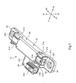
- Fig. 1 is a perspective view illustrating an overall structure of the antenna device 10.
- Fig. 2 is a side cross-sectional view illustrating the structure of the antenna device 10.
- the antenna device 10 has, as main components, a core body 20, a bobbin 30, a coil 40, and a case 50.
- Fig. 3 is a perspective view illustrating a structure of the core body 20.
- Fig. 4 is a partial side cross-sectional view illustrating a structure in the vicinity where a cap 22 is attached to the core body 20.
- the core body 20 includes a core 21 and a cap 22.
- the core 21 is formed of a magnetic material and is provided in a long shape in an X direction. Further, the core 21 has a rectangular cross section when seen from the front.
- the core 21 is constituted of a magnetic material, and as the magnetic material it is possible to use, for example, one of various types of magnetic materials such as ferrite, such as nickel-based ferrite or manganese-based ferrite, permalloy, and sendust, and mixtures of various types of magnetic materials.
- the cap 22 is attached so as to cover an outer peripheral side of the one end side (X1 side) of the core 21 and an end face of the one end side (X1 side).
- This cap 22 is formed of a resin as a material.
- the cap 22 has a block part 221 and a cylindrical part 222.
- the block part 221 is a block-shaped part located on the X1 side from the end face of the one end side (X1 side) of the core 21. From this block part 221, the cylindrical part 222 is provided to be directed toward the other end side (X2 side) of the core 21.
- the cylindrical part 222 is provided in a cylindrical shape so as to cover the outer peripheral surface of the core 21.
- the cap 22 barely enters an insertion through hole 311 of the bobbin 30 and is located outside the bobbin 30, but enters the insertion hole 511 of a case 50, which will be described later.
- the cap 22 is provided with plural (four in Fig. 3 and Fig. 4 ) fins 223.
- the fins 223 are projecting parts preventing the core body 20 from being pulled out of the insertion hole 511 when the core body 20 is inserted in the insertion hole 511 of the case 50, which will be described later. Note that on the X1 side of the fin 223, a face orthogonal to a longitudinal direction (X direction) of the core body 20 exists, and on the X2 side of this orthogonal face, a slope gradually declining toward the core 21 exists.
- the cap 22 is provided with a fitting projection 224.
- the fitting projection 224 also is a part to be a pulling-out preventer preventing the core body 20 from being pulled out of the insertion hole 511.
- the fitting projection 224 enters a fitting hole 514 of the case 50, which will be described later.
- the fitting projection 224 functions as a pulling-out preventer of the core body 20.
- a face 224a orthogonal to the longitudinal direction (X direction) of the core body 20 exists, but on the X2 side of this orthogonal face 224a, a slope 224b gradually declining toward the core 21 exists.
- the slope 224b is a part to function as a guide for fitting the fitting projection 224 into the fitting hole 514
- the orthogonal face 224a is a part to function as a pulling-out preventer of the core body 20 by abutting on an inside wall of the fitting hole 514.
- fitting projection 224 and the fitting hole 514 function as a pulling-out restriction part.
- the bobbin 30 is formed of, for example, a thermoplastic resin such as PBT (polybutylene terephthalate) resin as a material.
- Fig. 5 is a perspective view illustrating a structure of the bobbin 30. As illustrated in Fig. 5 , the bobbin 30 has a cylindrical body part 31 and a terminal attachment part 32.
- the cylindrical body part 31 is a part having a cylindrical shape covering the core 21, is formed to be shorter than the length of the core 21, and is provided so that the one end side and the other end side of the core 21 project from the cylindrical body part 31.
- the cylindrical body part 31 is provided with the insertion through hole 311.
- the insertion through hole 311 is a hole penetrating through the cylindrical body part 31, and the core 21 is inserted in this insertion through hole 311.
- the insertion through hole 311 is provided to have a rectangular shape corresponding to the rectangular shape which is the cross-sectional shape of the core 21, and the insertion through hole 311 is formed larger than the cross-sectional shape of the core 21 to an extent that allows easily inserting the core 21.
- it may be structured to restrict, by the cap 22 reaching the insertion through hole 311, the core 21 from pushed into the insertion through hole 311.
- the cylindrical body part 31 is provided with a winding frame part 312 and sealing parts 313.
- the winding frame part 312 is a part on which the coil 40 is disposed, and is formed to recess from the sealing parts 313.
- the coil 40 disposed on the winding frame part 312 does not project more than the sealing parts 313, and is in a state that it is also possible to perform positioning of the coil 40.
- sealing parts 313 are provided on both end sides sandwiching the winding frame part 312 in the structure illustrated in Fig. 5 .
- the sealing parts 313 are formed to project outward from the winding frame part 312 (toward the side departing from a center line of the insertion through hole 311).
- the sealing part 313 on one end side X1 side
- the sealing part 313 on the other end side is referred to as a sealing part 313b.
- Each sealing part 313 is provided with fins 314 corresponding to a projecting part.
- Plural (four each in Fig. 5 ) fins 314 are provided, which project in an annular form so as to extend across an outer periphery of the sealing part 313.
- These fins 314 are parts which abut on inside walls 511 a of an insertion hole 511 of the case 50, which will be described later.
- the fins 314 seal the insertion hole 511 from the outside.
- the case 50 is formed by injection molding after the bobbin 30 in a state that the coil 40 is formed thereon is placed in a mold.
- tip sides of the fins 314 melt to form an integrated part M integrated with the case 50 (inside walls 511 a of the case 50 in particular).
- an integrated part M By formation of such an integrated part M, sealing property of the insertion hole from the outside improves, and thus waterproof property can be improved.
- the bobbin 30 is provided with a guide trench 315.
- the guide trench 315 is a trench part for guiding a conducting wire to be bound to a connection terminal 60 (60a), which will be described later.
- a portion of this guide trench 315 is formed in the terminal attachment part 32, but a main portion of the guide trench 315 is formed in the cylindrical body part 31 and is formed in particular across the entire X direction of the winding frame part 312.
- the guide trench 315 is provided to recess from the winding frame part 312, and is formed such that the depth of the recess is to an extent of allowing sufficient insertion of the lead wire.
- the guide trench 315 is provided to continue to a vertical trench 316.
- the vertical trench 316 is formed by recessing an outer peripheral surface along the vertical direction (Z direction) of the sealing part 313b toward the Y2 side.
- the vertical trench 316 is provided to recess toward the Y2 side from the outer peripheral surface along the vertical direction (Z direction) of the winding frame part 312.
- a flange part 317 partitioning them is provided between the vertical trench 316 and the winding frame part 3112.
- the flange part 317 is provided to project toward the Y1 side from the winding frame part 312.
- the flange part 317 is provided to project also toward a lower side (Z2 side) and an upper side (Z1 side).
- the conducting wire passed through the vertical trench 316 is routed around the lower side of this flange part 317 and is guided to the winding frame part 312.
- the conducting wire passed through the vertical trench 316 and wound on the winding frame part 312 to form the coil 40 is routed around an end portion of a flange part 319 and then introduced into a wiring trench 318.
- the function of the wiring trench 318 is similar to the above-described guide trench 315 and vertical trench 316. However, there is a difference such that the guide trench 315 and the vertical trench 316 are parts the conducting wire enters before forming the coil 40, whereas the wiring trench 318 is a part the conducting wire enters after forming the coil 40.
- the wiring trench 318 is provided from a portion adjacent to the sealing part 313a to a portion where a connection terminal 60 (60b) of the terminal attachment part 32 exists in the cylindrical body part 31.
- the terminal attachment part 32 is provided to project toward the Y1 side from a portion adjacent to the sealing part 313a in a side face of the cylindrical body part 31.
- This terminal attachment part 32 is a part to which the connection terminals 60 are attached.
- the terminal attachment part 32 is provided with holes (not illustrated) for inserting the connection terminals 60, and the connection terminals 60 are attached by inserting the connection terminals 60 in the holes.
- they may be formed by inserting the connection terminals 60 when the case 50 is formed by injection molding.
- a capacitor 61 is attached to the terminal attachment part 32. Then, one side of the capacitor 61 is attached to the connection terminal 60a, and the other side of the capacitor 61 is connected to the connection terminal 60c.
- a structure omitting the capacitor 61 may be employed, and in this case, the connection terminal 60a has the same structure as the connection terminal 60b.
- the coil 40 is a part formed by winding the conducting wire.
- the coil 40 is of single layer winding (wound by only one layer), but the coil 40 may also be of multilayer winding.
- the case 50 covers a part excluding the insertion through hole 311 of the bobbin 30 to which the coil 40 is attached.
- the case 50 has a case main body 51, flange parts 52, and a side projecting part 53.
- the case main body 51 is a part provided to be cylindrical in the case 50, and has the insertion hole 511 extending along a longitudinal direction (X direction).
- the case main body 51 is provided to be cylindrical with a bottom in which opening on the other end side of the insertion hole 511 is blocked, which is different from the cylindrical body part 31 of the bobbin 30.
- the case 50 is formed of, for example, a thermoplastic resin such as PBT (polybutylene terephthalate) resin as a material.
- PBT polybutylene terephthalate
- the integrated part M can be formed easily by that the fins 314 are integrated with the inside walls 511a of the case 50.
- the bobbin 30 and the case 50 may be of different materials.
- the bobbin 30 on which the coil 40 is formed is located in the insertion hole 511.
- the core body 20 is located in a state of being inserted in the insertion through hole 311 of the bobbin 30, but the one end side and the other end side of the core body 20 project from the insertion through hole 311 and directly located in the insertion hole 511.
- Fig. 6 is a front cross-sectional view of an area where the locking projections 512 exist in the antenna device 10. As illustrated in Fig. 6 , the locking projections 512 project from the inside walls 511a of a bottom surface, a top surface, and side surfaces.
- an area (rectangular area in this embodiment) obtained by coupling distal end sides of these locking projections 512 is made slightly smaller than a cross-sectional shape of the core 21.
- the core 21 is in a state of being held tight favorably by the locking projections 512 without a backlash.
- one locking projection 512 projects from each side face, but two locking projections 512 are formed to project from each of the top surface and the bottom surface which have a larger area than the side face. Further, as illustrated in Fig. 2 , the locking projections 512 are provided to have a long shape which is long in the X direction.
- the case main body 51 is provided with recessed parts 513.
- the recessed parts 513 are provided on both end sides of the longitudinal direction (X direction) of the case main body 51, and each formed by recessing from an outer peripheral side of the case main body 51.
- the bobbin 30 is provided with positioning projections 31a, and distal ends of these positioning projections 31a abut on portions projecting on insides of a mold (mold inside walls or inserts).
- the position of the bobbin 30 is determined inside the mold, and parts corresponding to the projecting portions are the recessed parts 513.
- the recessed parts 513 are provided respectively in end portion sides in a width direction (Y direction) of the case main body 51, and also provided respectively in end portions in a longitudinal direction (X direction) (four in total).
- the case main body 51 is provided with a fitting hole 514.
- the fitting hole 514 is located to be biased to the end portion of the one end side (X1 side) in a top surface of the case main body 51, and moreover, when the core body 20 is inserted in the insertion hole 511, it is disposed to be located on the upper side of the block part 221.
- This fitting hole 514 is a hole which the above-described fitting projection 224 fits in. With an inside wall on the X1 side of this fitting hole 514, the above-described orthogonal face 224a comes in contact to restrict movement of the core body 20 toward the X1 side. Thus, it is possible to prevent the core body 20 from being pulled out of the insertion hole 511.
- flange parts 52 are provided continuously on the case main body 51.
- the flange parts 52 are parts which come in contact with an attachment area of a vehicle or the like when the antenna device 10 is attached to the attachment area. At this time, it is possible to separate the case main body 51 from the attachment area of the vehicle or the like. To enable such separation of the case main body 51, a lower surface of the flange part 52 is provided to project further downward from the lower surface of the case main body 51.
- the flange parts 52 are provided to project toward the one end side (X1 side) and the other end side (X2 side), respectively, from the case main body 51. Further, an attachment hole 521 is provided in each flange part 52.
- the attachment hole 521 penetrates the flange part 52, and a fastening means such as a screw is inserted therein. Thus, it is possible to fix the antenna device 10 to the attachment area of a vehicle or the like. Note that in the structure illustrated in Fig. 2 , one of the pair of attachment holes 521 is provided to have a long hole shape.
- a side projecting part 53 is formed to project from a side on the Y1 side of the case main body 51.
- the side projecting part 53 is a part to cover the terminal attachment part 32.
- the side projecting part 53 also covers the connection terminals 60. That is, the bobbin 30 is placed inside the mold in a state that the connection terminals 60 are inserted in the holes of the terminal attachment part 32.
- the case 50 is injection molded in this state, and thus the side projecting part 53 is in a state of covering the connection terminals 60 also.
- the portion in the side projecting part 53 extending in the Y direction to cover the terminal attachment part 32 will be referred to as a side cover part 531.
- a connector connecting part 532 is provided in the side projecting part 53.
- the connector connecting part 532 is a part projecting toward the X1 side from the side cover part 531.
- This connector connecting part 532 is a cylindrical part having a connector hole 533, and pin-like portions on the X1 side of the connection terminals 60b, 60c project inside the connector hole 533.
- the bobbin 30 is formed by, for example, molding in advance. Then, the connection terminals 60 are inserted in the holes of the terminal attachment part 32 of the bobbin 30. Next, one end of a conducting wire is bound on a binding part 60a1, the conducting wire is routed through the guide trench 315 and further routed through the vertical trench 316, and after the conducting wire is routed around the lower side of the flange part 317, the conducting wire is guided to the winding frame part 312. Then the conducting wire is wound on the winding frame part 312 to form the coil 40.
- the conducting wire is routed around the lower side of the flange part 319, and the conducting wire is routed through the wiring trench 318 and guided to the connection terminal 60b. Then, the conducting wire is bound on a binding part 60b1.
- the conducting wire is wound to be a single layer winding (in a state of being wound by one layer) to form the coil 40.
- the conducting wire may be wound to be a multilayer winding to form the coil 40. Note that before and after forming this coil 40, the capacitor 61 may be attached to the terminal attachment part 32.
- the bobbin 30 is set inside the mold.
- the positioning projections 31a are made to abut on the portions projecting on the insides of the mold (mold inside walls or inserts) to position the bobbin 30 inside the mold.
- a core corresponding to the insertion hole 511 is inserted in the insertion through hole 311, and other preparations before injection molding are completed.
- a molten thermoplastic resin is poured into the mold with a predetermined injection pressure, so as to perform molding. Then, the temperature in the mold is lowered to cure the resin poured in, thereby forming the case 50. Thereafter, an upper die and a lower die of the mold are released to take out the antenna device 10 in a state that the case 50 is formed.
- the cap 22 is attached to the core 21 to form the core body 20. Thereafter, the core body 20 is inserted in the insertion hole 511. At this time, as the core body 20 is inserted in the deep side of the insertion hole 511, the deep side of the core 21 is brought into a state of being held tight by the plural locking projections 512. As the core body 20 is further inserted in the insertion hole 511, the fitting projection 224 fits in the fitting hole 514. Thus, insertion of the core body 20 is completed. As described above, the antenna device 10 in which the core body 20 is inserted in the insertion hole 511 (insertion through hole 311) is formed after the case 50 is molded.
- the core body 20 is inserted in the insertion hole 511 of the case 50 after the case 50 is formed by molding, and after this insertion, the core body 20 is retained inside the insertion hole 511.
- a structure is made possible in which the core body 20 does not exist in the insertion hole 511 during molding of the case 50, and a state that pressure (such as injection pressure) is not applied to the core body 20 (core 21) can be created during molding of the case 50.
- pressure such as injection pressure
- the case 50 contracts after molding the case 50 made of resin, it is possible to prevent application of pressure by this contraction to the core body 20 (core 21).
- variations of characteristics of the core 21, such as inductance can be suppressed, and fluctuation of characteristics of the antenna device 10 can be suppressed.
- the antenna device 10 can be formed in a state that high pressure (injection pressure or the like) during molding of the case 50 is not applied, it is possible to prevent cracking of the core 21.
- the vicinity of the coil 40 is covered with the molded case 50, and thus waterproof property of the coil 40 can be enhanced.
- the core body 20 (core 21) is locked in a pressed state by the locking projections 512 inside the insertion hole 511, and a portion excluding the part retained by the locking projections 512 and the cap 22 in the core 21 exists with a gap from the inside walls 511 a of the insertion hole 511.
- pressure to be applied to the core 21 can be reduced, and variations of characteristics of the core 21, such as inductance, can be suppressed more reliably.
- the deep side (X2 side) with a bottom in the insertion hole 511 is provided with the locking projections 512 supporting the core body 20 in a tightly held state. Accordingly, it is possible to reliably hold the core body 20 (core 21) in a state that the core body 20 has no backlash in the insertion hole 511. Further, it is possible to reduce contact portions of the case 50 with the core 21 by the structure such that the locking projections 512 abut on the core 21, and thus variations of characteristics of the core 21, such as inductance, can be suppressed more reliably.
- the fins 314 are provided on the outer peripheral side of the bobbin 30, and the fins 314 form the integrated part M with the inside walls 511 a of the case 50.
- the existence of the fins 314 hinders formation of a gap between the bobbin 30 and the case 50.
- the core body 20 is provided with the cap 22, and between the case 50 and the cap 22, the fitting projection 224 and the fitting hole 514 constituting a pulling-out restriction part are provided.
- the core body 20 is provided with the cap 22, and between the case 50 and the cap 22, the fitting projection 224 and the fitting hole 514 constituting a pulling-out restriction part are provided.
- the case main body 51 is provided to be cylindrical with a bottom with the opening on the other end side (X2 side) of the insertion hole 511 being blocked.
- the other end side may be opened without being blocked.
- the locking projections 512 locking the core 21 are provided to project from the inside walls of the insertion hole 511 of the case main body 51.
- such locking projections may be provided inside the insertion through hole 311 of the bobbin 30.
- the core body 20 can be held favorably.
- the locking projections may be provided only in the insertion through hole 311, or may be provided in both the insertion hole 511 and the insertion through hole 311.
- the core body 20 is formed of the core 21 and the cap 22.
- the core body 20 may be formed only of the core 21.
- a projecting part similar to the fitting projection may be provided on the core 21, allowing this projecting part to function as a pulling-out restriction part.
- the bobbin 30 is provided with fins 314 in the above-described embodiment, a structure in which these fins 314 are omitted may be employed. Further, the fins 314 need not be provided to have an annular form, and may be provided to have, for example, a form other than the annular form, such as a spiral form or an arch form.
- the locking projections 512 are in a state of being pressed against the core 21 without adhering thereto. That is, the interface between the core 21 and the locking projections 512 is not bonded, and is in a state that they can be easily separated when the pressing force is released.
- a structure in which an adhesive layer formed by applying an adhesive intervenes between the core 21 and the locking projections 512 may be employed. Note that the adhesive layer may employ a structure to exist in a portion other than the portion to abut on the locking projections 512 of the core 21 in the core body 20.
Landscapes
- Engineering & Computer Science (AREA)
- Remote Sensing (AREA)
- Computer Security & Cryptography (AREA)
- Radar, Positioning & Navigation (AREA)
- Coils Or Transformers For Communication (AREA)
- Details Of Aerials (AREA)
- Support Of Aerials (AREA)
Abstract
Description
- The present invention relates to an antenna device and a manufacturing method of an antenna device.
- In recent years, vehicles have been increasing that have an antenna device mounted for receiving a signal for locking or unlocking a door. As such an antenna device, for example, there is one disclosed in Patent Document 1. In a structure disclosed in Patent Document 1, after a coil is formed on a core (magnetic body), a case is formed by molding so as to cover an outer peripheral side of a core.
- [Patent Document 1] Japanese Patent Application Laid-open No.
2006-121278 - Incidentally, in the structure disclosed in Patent Document 1, the case is formed by molding so as to cover the outer peripheral side of the core. Thus, reliability of waterproof property in the coil part is increased. However, there is a problem that characteristics of the core, such as inductance, are changed by pressure applied to the core during molding, contraction of the plastic case after molding, and the like. Further, there is another problem that the core cracks by large pressure applied to the core during molding.
- The present invention is made in view of such problems, and it is an object thereof to provide an antenna device capable of securing waterproof property while suppressing changes of characteristics of the core, and a manufacturing method of an antenna device. Further, preferably, it is another object thereof to provide an antenna device capable of preventing cracking of the core, and a manufacturing method of an antenna device.
- In order to solve the above problems, one aspect of an antenna device of the present invention has: a core body having a core formed of a magnetic material; a bobbin having an insertion through hole in which the core body is inserted; a coil disposed in a vicinity of the bobbin; and a case which covers the coil in the vicinity of the bobbin in a state of sealing from an outside, has an insertion hole allowing the core body to be inserted therein in a state of communicating with the insertion through hole, and retains the core body inside the insertion hole after the core body is inserted.
- Further, in another aspect of the antenna device of the present invention, in addition to the above-described invention, preferably, the core body is provided to have a long shape, and at least one of one end side and another end side in a longitudinal direction of the core body is locked in a pressed state inside the insertion hole, and a portion between the one end side and the other end side in the longitudinal direction of the core body exists separately with a gap from an inside wall surface of the insertion hole.
- Moreover, in another aspect of the antenna device of the present invention, in addition to the above-described invention, preferably, either one of the one end side and the other end side of the insertion hole is blocked, and locking projections supporting the core body in a tightly holding state are provided on a blocked deep side in the insertion hole.
- Further, in another aspect of the antenna device of the present invention, in addition to the above-described invention, preferably, an outer peripheral side of the bobbin is provided with a circumferential projecting part projecting toward the case for sealing the coil from an outside, and at least a distal end side of the projecting part is integrated with an inner peripheral side of the case to form an integrated part.
- Moreover, in another aspect of the antenna device of the present invention, in addition to the above-described invention, preferably, the core body is provided with a cap attached to the core, and a pulling-out restriction part which restricts the core body from being pulled out of the insertion hole is provided between the case and the cap.
- Further, one aspect of a manufacturing method of an antenna device of the present invention has: a coil forming step of forming a coil by winding a conducting wire around a bobbin having an insertion through hole for inserting the core body having a core formed of a magnetic material; a setting step of setting the bobbin to a predetermined position inside a mold after the coil forming step; a case forming step of pouring a molten resin into the mold to form a case covering a vicinity of the bobbin in a state that the coil is sealed from an outside; and a core body attaching step of inserting the core body in an insertion hole communicating with the insertion through hole in the case formed in the case forming step, to thereby retain the core body in the insertion hole.
- According to the present invention, it becomes possible to secure waterproof property while suppressing changes of characteristics of the core. Further, it becomes also possible to prevent cracking of a core.
-
-
Fig. 1 is a perspective view illustrating an overall structure of an antenna device according to one embodiment of the present invention; -
Fig. 2 is a side cross-sectional view illustrating the structure of the antenna device ofFig. 1 ; -
Fig. 3 is a perspective view illustrating a structure of a core body ofFig. 1 ; -
Fig. 4 is a partial side cross-sectional view illustrating a structure in the vicinity where a cap is attached to the core body ofFig. 1 ; -
Fig. 5 is a perspective view illustrating a structure of a bobbin ofFig. 1 ; and -
Fig. 6 is a front cross-sectional view of an area where locking projections exist in the antenna device ofFig. 1 . - Hereinafter, an
antenna device 10 according to one embodiment of the present invention will be described with reference to the drawings. - Note that in the following description, the side where a
flange part 52 is located is a lower side (Z2 side), and the opposite side thereof is an upper side (Z1 side). Further, the side where an opening of aninsertion hole 511 exists is one end side (X1 side), and the opposite side thereof where the opening of theinsertion hole 511 does not exist is another end side (X2 side). Further, inFig. 1 , a direction orthogonal to the X direction and the Z direction is a Y direction, and the left side is a Y1 side and the opposite right side is a Y2 side. -
Fig. 1 is a perspective view illustrating an overall structure of theantenna device 10.Fig. 2 is a side cross-sectional view illustrating the structure of theantenna device 10. As illustrated inFig. 1 andFig. 2 , theantenna device 10 has, as main components, acore body 20, abobbin 30, acoil 40, and acase 50. -
Fig. 3 is a perspective view illustrating a structure of thecore body 20.Fig. 4 is a partial side cross-sectional view illustrating a structure in the vicinity where acap 22 is attached to thecore body 20. Thecore body 20 includes acore 21 and acap 22. Thecore 21 is formed of a magnetic material and is provided in a long shape in an X direction. Further, thecore 21 has a rectangular cross section when seen from the front. Note that thecore 21 is constituted of a magnetic material, and as the magnetic material it is possible to use, for example, one of various types of magnetic materials such as ferrite, such as nickel-based ferrite or manganese-based ferrite, permalloy, and sendust, and mixtures of various types of magnetic materials. - The
cap 22 is attached so as to cover an outer peripheral side of the one end side (X1 side) of thecore 21 and an end face of the one end side (X1 side). Thiscap 22 is formed of a resin as a material. Thecap 22 has ablock part 221 and acylindrical part 222. Theblock part 221 is a block-shaped part located on the X1 side from the end face of the one end side (X1 side) of thecore 21. From thisblock part 221, thecylindrical part 222 is provided to be directed toward the other end side (X2 side) of thecore 21. Thecylindrical part 222 is provided in a cylindrical shape so as to cover the outer peripheral surface of thecore 21. - Note that as illustrated in
Fig. 2 , thecap 22 barely enters an insertion throughhole 311 of thebobbin 30 and is located outside thebobbin 30, but enters theinsertion hole 511 of acase 50, which will be described later. - Further, the
cap 22 is provided with plural (four inFig. 3 andFig. 4 )fins 223. Thefins 223 are projecting parts preventing thecore body 20 from being pulled out of theinsertion hole 511 when thecore body 20 is inserted in theinsertion hole 511 of thecase 50, which will be described later. Note that on the X1 side of thefin 223, a face orthogonal to a longitudinal direction (X direction) of thecore body 20 exists, and on the X2 side of this orthogonal face, a slope gradually declining toward thecore 21 exists. - Further, the
cap 22 is provided with afitting projection 224. Similarly to thefins 223, thefitting projection 224 also is a part to be a pulling-out preventer preventing thecore body 20 from being pulled out of theinsertion hole 511. However, thefitting projection 224 enters afitting hole 514 of thecase 50, which will be described later. By this, thefitting projection 224 functions as a pulling-out preventer of thecore body 20. Here, on thefitting projection 224, aface 224a orthogonal to the longitudinal direction (X direction) of thecore body 20 exists, but on the X2 side of thisorthogonal face 224a, aslope 224b gradually declining toward thecore 21 exists. Theslope 224b is a part to function as a guide for fitting thefitting projection 224 into thefitting hole 514, and theorthogonal face 224a is a part to function as a pulling-out preventer of thecore body 20 by abutting on an inside wall of thefitting hole 514. - Note that the
fitting projection 224 and thefitting hole 514 function as a pulling-out restriction part. - Next, the
bobbin 30 will be described. Thebobbin 30 is formed of, for example, a thermoplastic resin such as PBT (polybutylene terephthalate) resin as a material.Fig. 5 is a perspective view illustrating a structure of thebobbin 30. As illustrated inFig. 5 , thebobbin 30 has acylindrical body part 31 and aterminal attachment part 32. Thecylindrical body part 31 is a part having a cylindrical shape covering thecore 21, is formed to be shorter than the length of the core 21, and is provided so that the one end side and the other end side of the core 21 project from thecylindrical body part 31. - The
cylindrical body part 31 is provided with the insertion throughhole 311. The insertion throughhole 311 is a hole penetrating through thecylindrical body part 31, and thecore 21 is inserted in this insertion throughhole 311. Thus, the insertion throughhole 311 is provided to have a rectangular shape corresponding to the rectangular shape which is the cross-sectional shape of the core 21, and the insertion throughhole 311 is formed larger than the cross-sectional shape of the core 21 to an extent that allows easily inserting thecore 21. However, it may be structured to restrict, by thecap 22 reaching the insertion throughhole 311, the core 21 from pushed into the insertion throughhole 311. - Further, the
cylindrical body part 31 is provided with a windingframe part 312 and sealingparts 313. The windingframe part 312 is a part on which thecoil 40 is disposed, and is formed to recess from the sealingparts 313. Thus, thecoil 40 disposed on the windingframe part 312 does not project more than the sealingparts 313, and is in a state that it is also possible to perform positioning of thecoil 40. - Further, the sealing
parts 313 are provided on both end sides sandwiching the windingframe part 312 in the structure illustrated inFig. 5 . The sealingparts 313 are formed to project outward from the winding frame part 312 (toward the side departing from a center line of the insertion through hole 311). In the following description, when it is necessary to distinguish the pair of sealingparts 313, the sealingpart 313 on one end side (X1 side) is referred to as a sealingpart 313a, and the sealingpart 313 on the other end side is referred to as a sealingpart 313b. - Each sealing
part 313 is provided withfins 314 corresponding to a projecting part. Plural (four each inFig. 5 )fins 314 are provided, which project in an annular form so as to extend across an outer periphery of the sealingpart 313. Thesefins 314 are parts which abut oninside walls 511 a of aninsertion hole 511 of thecase 50, which will be described later. Thus, thefins 314 seal theinsertion hole 511 from the outside. Here, as will be described later, thecase 50 is formed by injection molding after thebobbin 30 in a state that thecoil 40 is formed thereon is placed in a mold. Then, due to the temperature and so on during the injection molding, tip sides of thefins 314 melt to form an integrated part M integrated with the case 50 (insidewalls 511 a of thecase 50 in particular). By formation of such an integrated part M, sealing property of the insertion hole from the outside improves, and thus waterproof property can be improved. - Further, the
bobbin 30 is provided with aguide trench 315. Theguide trench 315 is a trench part for guiding a conducting wire to be bound to a connection terminal 60 (60a), which will be described later. A portion of thisguide trench 315 is formed in theterminal attachment part 32, but a main portion of theguide trench 315 is formed in thecylindrical body part 31 and is formed in particular across the entire X direction of the windingframe part 312. Theguide trench 315 is provided to recess from the windingframe part 312, and is formed such that the depth of the recess is to an extent of allowing sufficient insertion of the lead wire. - Further, the
guide trench 315 is provided to continue to avertical trench 316. Thevertical trench 316 is formed by recessing an outer peripheral surface along the vertical direction (Z direction) of the sealingpart 313b toward the Y2 side. Thevertical trench 316 is provided to recess toward the Y2 side from the outer peripheral surface along the vertical direction (Z direction) of the windingframe part 312. - Further, between the
vertical trench 316 and the windingframe part 312, aflange part 317 partitioning them is provided. Theflange part 317 is provided to project toward the Y1 side from the windingframe part 312. In addition, theflange part 317 is provided to project also toward a lower side (Z2 side) and an upper side (Z1 side). In particular, by theflange part 317 provided to project toward the lower side (Z2 side), the conducting wire passed through thevertical trench 316 is routed around the lower side of thisflange part 317 and is guided to the windingframe part 312. Thus, it is possible to route the conducting wire in a position recessed from the windingframe part 312 and the sealingpart 313b, and it is possible to prevent breakage of the conducting wire when large pressure is applied during injection molding of thecase 50. - Note that as illustrated in
Fig. 5 , the conducting wire passed through thevertical trench 316 and wound on the windingframe part 312 to form thecoil 40 is routed around an end portion of aflange part 319 and then introduced into awiring trench 318. The function of thewiring trench 318 is similar to the above-describedguide trench 315 andvertical trench 316. However, there is a difference such that theguide trench 315 and thevertical trench 316 are parts the conducting wire enters before forming thecoil 40, whereas thewiring trench 318 is a part the conducting wire enters after forming thecoil 40. Thewiring trench 318 is provided from a portion adjacent to the sealingpart 313a to a portion where a connection terminal 60 (60b) of theterminal attachment part 32 exists in thecylindrical body part 31. - Further, the
terminal attachment part 32 is provided to project toward the Y1 side from a portion adjacent to the sealingpart 313a in a side face of thecylindrical body part 31. Thisterminal attachment part 32 is a part to which theconnection terminals 60 are attached. In this embodiment, theterminal attachment part 32 is provided with holes (not illustrated) for inserting theconnection terminals 60, and theconnection terminals 60 are attached by inserting theconnection terminals 60 in the holes. However, they may be formed by inserting theconnection terminals 60 when thecase 50 is formed by injection molding. - Note that in this embodiment, a
capacitor 61 is attached to theterminal attachment part 32. Then, one side of thecapacitor 61 is attached to theconnection terminal 60a, and the other side of thecapacitor 61 is connected to theconnection terminal 60c. However, a structure omitting thecapacitor 61 may be employed, and in this case, theconnection terminal 60a has the same structure as theconnection terminal 60b. - Further, the
coil 40 is a part formed by winding the conducting wire. In this embodiment, thecoil 40 is of single layer winding (wound by only one layer), but thecoil 40 may also be of multilayer winding. - Next, the
case 50 will be described. Thecase 50 covers a part excluding the insertion throughhole 311 of thebobbin 30 to which thecoil 40 is attached. As illustrated inFig. 1 , thecase 50 has a casemain body 51,flange parts 52, and aside projecting part 53. The casemain body 51 is a part provided to be cylindrical in thecase 50, and has theinsertion hole 511 extending along a longitudinal direction (X direction). However, the casemain body 51 is provided to be cylindrical with a bottom in which opening on the other end side of theinsertion hole 511 is blocked, which is different from thecylindrical body part 31 of thebobbin 30. - Note that the
case 50 is formed of, for example, a thermoplastic resin such as PBT (polybutylene terephthalate) resin as a material. Here, when thebobbin 30 and thecase 50 are of the same material, the integrated part M can be formed easily by that thefins 314 are integrated with theinside walls 511a of thecase 50. However, thebobbin 30 and thecase 50 may be of different materials. Further, it is preferred that thefins 314 form the integrated part M with theinside walls 511a of thecase 50, but thefins 314 need not form the integrated part M. - The
bobbin 30 on which thecoil 40 is formed is located in theinsertion hole 511. In addition, in theinsertion hole 511, thecore body 20 is located in a state of being inserted in the insertion throughhole 311 of thebobbin 30, but the one end side and the other end side of thecore body 20 project from the insertion throughhole 311 and directly located in theinsertion hole 511. - Here, as illustrated in
Fig. 2 , on a deep side (X2 side) of theinsertion hole 511, lockingprojections 512 are provided to project from theinside walls 511a. The lockingprojections 512 are projections for locking the core 21 located on the deep side (X2 side) to suppress a backlash of thecore body 20, and to prevent thecore body 20 from being pulled out of theinsertion hole 511.Fig. 6 is a front cross-sectional view of an area where the lockingprojections 512 exist in theantenna device 10. As illustrated inFig. 6 , the lockingprojections 512 project from theinside walls 511a of a bottom surface, a top surface, and side surfaces. Then, an area (rectangular area in this embodiment) obtained by coupling distal end sides of these lockingprojections 512 is made slightly smaller than a cross-sectional shape of thecore 21. Thus, thecore 21 is in a state of being held tight favorably by the lockingprojections 512 without a backlash. - Note that in the structure illustrated in
Fig. 6 , onelocking projection 512 projects from each side face, but two lockingprojections 512 are formed to project from each of the top surface and the bottom surface which have a larger area than the side face. Further, as illustrated inFig. 2 , the lockingprojections 512 are provided to have a long shape which is long in the X direction. - Further, the case
main body 51 is provided with recessedparts 513. The recessedparts 513 are provided on both end sides of the longitudinal direction (X direction) of the casemain body 51, and each formed by recessing from an outer peripheral side of the casemain body 51. Here, as illustrated inFig. 5 , thebobbin 30 is provided withpositioning projections 31a, and distal ends of thesepositioning projections 31a abut on portions projecting on insides of a mold (mold inside walls or inserts). Thus, the position of thebobbin 30 is determined inside the mold, and parts corresponding to the projecting portions are the recessedparts 513. In this embodiment, the recessedparts 513 are provided respectively in end portion sides in a width direction (Y direction) of the casemain body 51, and also provided respectively in end portions in a longitudinal direction (X direction) (four in total). - Further, the case
main body 51 is provided with afitting hole 514. Thefitting hole 514 is located to be biased to the end portion of the one end side (X1 side) in a top surface of the casemain body 51, and moreover, when thecore body 20 is inserted in theinsertion hole 511, it is disposed to be located on the upper side of theblock part 221. Thisfitting hole 514 is a hole which the above-describedfitting projection 224 fits in. With an inside wall on the X1 side of thisfitting hole 514, the above-describedorthogonal face 224a comes in contact to restrict movement of thecore body 20 toward the X1 side. Thus, it is possible to prevent thecore body 20 from being pulled out of theinsertion hole 511. - Further,
flange parts 52 are provided continuously on the casemain body 51. Theflange parts 52 are parts which come in contact with an attachment area of a vehicle or the like when theantenna device 10 is attached to the attachment area. At this time, it is possible to separate the casemain body 51 from the attachment area of the vehicle or the like. To enable such separation of the casemain body 51, a lower surface of theflange part 52 is provided to project further downward from the lower surface of the casemain body 51. Theflange parts 52 are provided to project toward the one end side (X1 side) and the other end side (X2 side), respectively, from the casemain body 51. Further, anattachment hole 521 is provided in eachflange part 52. Theattachment hole 521 penetrates theflange part 52, and a fastening means such as a screw is inserted therein. Thus, it is possible to fix theantenna device 10 to the attachment area of a vehicle or the like. Note that in the structure illustrated inFig. 2 , one of the pair of attachment holes 521 is provided to have a long hole shape. - Further, as illustrated in
Fig. 1 , aside projecting part 53 is formed to project from a side on the Y1 side of the casemain body 51. Theside projecting part 53 is a part to cover theterminal attachment part 32. Note that theside projecting part 53 also covers theconnection terminals 60. That is, thebobbin 30 is placed inside the mold in a state that theconnection terminals 60 are inserted in the holes of theterminal attachment part 32. Thecase 50 is injection molded in this state, and thus theside projecting part 53 is in a state of covering theconnection terminals 60 also. In the following description, the portion in theside projecting part 53 extending in the Y direction to cover theterminal attachment part 32 will be referred to as aside cover part 531. - Further, a
connector connecting part 532 is provided in theside projecting part 53. Theconnector connecting part 532 is a part projecting toward the X1 side from theside cover part 531. Thisconnector connecting part 532 is a cylindrical part having aconnector hole 533, and pin-like portions on the X1 side of theconnection terminals connector hole 533. Thus, when an external connector is inserted in theconnector hole 533, this connector and theconnection terminals coil 40. - A manufacturing method of the
antenna device 10 structured as above will be described below. When theantenna device 10 is produced, thebobbin 30 is formed by, for example, molding in advance. Then, theconnection terminals 60 are inserted in the holes of theterminal attachment part 32 of thebobbin 30. Next, one end of a conducting wire is bound on a binding part 60a1, the conducting wire is routed through theguide trench 315 and further routed through thevertical trench 316, and after the conducting wire is routed around the lower side of theflange part 317, the conducting wire is guided to the windingframe part 312. Then the conducting wire is wound on the windingframe part 312 to form thecoil 40. - After forming the
coil 40, the conducting wire is routed around the lower side of theflange part 319, and the conducting wire is routed through thewiring trench 318 and guided to theconnection terminal 60b. Then, the conducting wire is bound on a binding part 60b1. On the windingframe part 312, the conducting wire is wound to be a single layer winding (in a state of being wound by one layer) to form thecoil 40. However, on the windingframe part 312, the conducting wire may be wound to be a multilayer winding to form thecoil 40. Note that before and after forming thiscoil 40, thecapacitor 61 may be attached to theterminal attachment part 32. - Next, in a state that the
core body 20 is not inserted in the insertion throughhole 311 of thebobbin 30, thebobbin 30 is set inside the mold. At this time, thepositioning projections 31a are made to abut on the portions projecting on the insides of the mold (mold inside walls or inserts) to position thebobbin 30 inside the mold. Then, a core corresponding to theinsertion hole 511 is inserted in the insertion throughhole 311, and other preparations before injection molding are completed. - Thereafter, a molten thermoplastic resin is poured into the mold with a predetermined injection pressure, so as to perform molding. Then, the temperature in the mold is lowered to cure the resin poured in, thereby forming the
case 50. Thereafter, an upper die and a lower die of the mold are released to take out theantenna device 10 in a state that thecase 50 is formed. - Further, separately from the above-described formation of the
coil 40 and formation of thecase 50, thecap 22 is attached to the core 21 to form thecore body 20. Thereafter, thecore body 20 is inserted in theinsertion hole 511. At this time, as thecore body 20 is inserted in the deep side of theinsertion hole 511, the deep side of thecore 21 is brought into a state of being held tight by theplural locking projections 512. As thecore body 20 is further inserted in theinsertion hole 511, thefitting projection 224 fits in thefitting hole 514. Thus, insertion of thecore body 20 is completed. As described above, theantenna device 10 in which thecore body 20 is inserted in the insertion hole 511 (insertion through hole 311) is formed after thecase 50 is molded. - In the
antenna device 10 structured as above, thecore body 20 is inserted in theinsertion hole 511 of thecase 50 after thecase 50 is formed by molding, and after this insertion, thecore body 20 is retained inside theinsertion hole 511. Thus, a structure is made possible in which thecore body 20 does not exist in theinsertion hole 511 during molding of thecase 50, and a state that pressure (such as injection pressure) is not applied to the core body 20 (core 21) can be created during molding of thecase 50. Further, when thecase 50 contracts after molding thecase 50 made of resin, it is possible to prevent application of pressure by this contraction to the core body 20 (core 21). Thus, variations of characteristics of the core 21, such as inductance, can be suppressed, and fluctuation of characteristics of theantenna device 10 can be suppressed. - Further, since the
antenna device 10 can be formed in a state that high pressure (injection pressure or the like) during molding of thecase 50 is not applied, it is possible to prevent cracking of thecore 21. - Moreover, the vicinity of the
coil 40 is covered with the moldedcase 50, and thus waterproof property of thecoil 40 can be enhanced. - Further, in this embodiment, the core body 20 (core 21) is locked in a pressed state by the locking
projections 512 inside theinsertion hole 511, and a portion excluding the part retained by the lockingprojections 512 and thecap 22 in thecore 21 exists with a gap from theinside walls 511 a of theinsertion hole 511. Thus, pressure to be applied to the core 21 can be reduced, and variations of characteristics of the core 21, such as inductance, can be suppressed more reliably. - Moreover, in this embodiment, the deep side (X2 side) with a bottom in the
insertion hole 511 is provided with the lockingprojections 512 supporting thecore body 20 in a tightly held state. Accordingly, it is possible to reliably hold the core body 20 (core 21) in a state that thecore body 20 has no backlash in theinsertion hole 511. Further, it is possible to reduce contact portions of thecase 50 with the core 21 by the structure such that the lockingprojections 512 abut on thecore 21, and thus variations of characteristics of the core 21, such as inductance, can be suppressed more reliably. - Further, in this embodiment, the
fins 314 are provided on the outer peripheral side of thebobbin 30, and thefins 314 form the integrated part M with theinside walls 511 a of thecase 50. The existence of thefins 314 hinders formation of a gap between thebobbin 30 and thecase 50. In addition, it is possible to suppress separation of thebobbin 30 and thecase 50. Thus, it is possible to improve waterproof property from the outside with respect to thecoil 40 existing between thebobbin 30 and thecase 50. That is, the existence of thefins 314 makes it possible to further improve waterproof property of thecoil 40. - Moreover, in this embodiment, the
core body 20 is provided with thecap 22, and between thecase 50 and thecap 22, thefitting projection 224 and thefitting hole 514 constituting a pulling-out restriction part are provided. Thus, it is possible to favorably prevent thecore body 20 from being pulled out of theinsertion hole 511. - In the foregoing, one embodiment of the present invention has been described, but the invention can be changed variously other than this embodiment. Such changes will be described below.
- In the above-described embodiment, the case
main body 51 is provided to be cylindrical with a bottom with the opening on the other end side (X2 side) of theinsertion hole 511 being blocked. However, in the case main body, the other end side may be opened without being blocked. - Further, in the above-described embodiment, the locking
projections 512 locking the core 21 are provided to project from the inside walls of theinsertion hole 511 of the casemain body 51. However, such locking projections may be provided inside the insertion throughhole 311 of thebobbin 30. Also by such a structure, thecore body 20 can be held favorably. Note that the locking projections may be provided only in the insertion throughhole 311, or may be provided in both theinsertion hole 511 and the insertion throughhole 311. - Further, in the above-described embodiment, the
core body 20 is formed of thecore 21 and thecap 22. However, thecore body 20 may be formed only of thecore 21. Further, a projecting part similar to the fitting projection may be provided on thecore 21, allowing this projecting part to function as a pulling-out restriction part. - Further, although the
bobbin 30 is provided withfins 314 in the above-described embodiment, a structure in which thesefins 314 are omitted may be employed. Further, thefins 314 need not be provided to have an annular form, and may be provided to have, for example, a form other than the annular form, such as a spiral form or an arch form. - Further, in the above-described embodiment, the locking
projections 512 are in a state of being pressed against thecore 21 without adhering thereto. That is, the interface between the core 21 and the lockingprojections 512 is not bonded, and is in a state that they can be easily separated when the pressing force is released. However, a structure in which an adhesive layer formed by applying an adhesive intervenes between the core 21 and the lockingprojections 512 may be employed. Note that the adhesive layer may employ a structure to exist in a portion other than the portion to abut on the lockingprojections 512 of the core 21 in thecore body 20. -
- 10
- antenna device
- 20
- core body
- 21
- core
- 22
- cap
- 30
- bobbin
- 31
- cylindrical body part
- 32
- terminal attachment part
- 40
- coil
- 50
- case
- 51
- case main body
- 52
- flange part
- 31a
- positioning projection
- 53
- side projecting part
- 60
- connection terminal
- 61
- capacitor
- 60a to 60c
- connection terminal
- 60a1, 60b1
- binding part
- 221
- block part
- 222
- cylindrical part
- 223
- fin
- 224
- fitting projection (corresponding to part of a pulling-out restriction part)
- 224a
- orthogonal face
- 224b
- slope
- 311
- insertion through hole
- 312
- winding frame part
- 313
- sealing part
- 313a, 313b
- sealing part
- 314
- fin (corresponding to a projecting part)
- 315
- guide trench
- 316
- vertical trench
- 317
- flange part
- 318
- wiring trench
- 319
- flange part,
- 511
- insertion hole
- 511a
- inside wall
- 512
- locking projection
- 513
- recessed part
- 514
- fitting hole (corresponding to part of a pulling-out restriction part)
- 521
- attachment hole
- 531
- side cover part
- 532
- connector connecting part
- 533
- connector hole
- M
- integrated part
Claims (6)
- An antenna device, comprising:a core body having a core formed of a magnetic material;a bobbin having an insertion through hole in which the core body is inserted;a coil disposed in a vicinity of the bobbin; anda case which covers the coil in the vicinity of the bobbin in a state of sealing from an outside, has an insertion hole allowing the core body to be inserted therein in a state of communicating with the insertion through hole, and retains the core body inside the insertion hole after the core body is inserted.
- The antenna device according to claim 1, wherein
the core body is provided to have a long shape, and
at least one of one end side and another end side in a longitudinal direction of the core body is locked in a pressed state inside the insertion hole, and a portion between the one end side and the other end side in the longitudinal direction of the core body exists separately with a gap from an inside wall surface of the insertion hole. - The antenna device according to claim 2, wherein
either one of the one end side and the other end side of the insertion hole is blocked, and locking projections supporting the core body in a tightly holding state are provided on a blocked deep side in the insertion hole. - The antenna device according to any one of claims 1 to 3, wherein
an outer peripheral side of the bobbin is provided with a circumferential projecting part projecting toward the case for sealing the coil from an outside, and at least a distal end side of the projecting part is integrated with an inner peripheral side of the case to form an integrated part. - The antenna device according to any one of claims 1 to 4, wherein t
he core body is provided with a cap attached to the core, and
a pulling-out restriction part which restricts the core body from being pulled out of the insertion hole is provided between the case and the cap. - A manufacturing method of an antenna device, the method comprising:a coil forming step of forming a coil by winding a conducting wire around a bobbin having an insertion through hole for inserting the core body having a core formed of a magnetic material;a setting step of setting the bobbin to a predetermined position inside a mold after the coil forming step;a case forming step of pouring a molten resin into the mold to form a case covering a vicinity of the bobbin in a state that the coil is sealed from an outside; anda core body attaching step of inserting the core body in an insertion hole communicating with the insertion through hole in the case formed in the case forming step, to thereby retain the core body in the insertion hole.
Applications Claiming Priority (1)
| Application Number | Priority Date | Filing Date | Title |
|---|---|---|---|
| JP2013105068A JP6229305B2 (en) | 2013-05-17 | 2013-05-17 | ANTENNA DEVICE AND ANTENNA DEVICE MANUFACTURING METHOD |
Publications (2)
| Publication Number | Publication Date |
|---|---|
| EP2804256A1 true EP2804256A1 (en) | 2014-11-19 |
| EP2804256B1 EP2804256B1 (en) | 2016-04-06 |
Family
ID=50735818
Family Applications (1)
| Application Number | Title | Priority Date | Filing Date |
|---|---|---|---|
| EP14001751.8A Active EP2804256B1 (en) | 2013-05-17 | 2014-05-17 | Antenna device and manufacturing method of antenna device |
Country Status (3)
| Country | Link |
|---|---|
| EP (1) | EP2804256B1 (en) |
| JP (1) | JP6229305B2 (en) |
| CN (2) | CN107732416B (en) |
Cited By (2)
| Publication number | Priority date | Publication date | Assignee | Title |
|---|---|---|---|---|
| EP3674055A1 (en) * | 2018-12-19 | 2020-07-01 | SUMIDA Components & Modules GmbH | Mould for forming a rod-shaped housing for a rod antenna, method for manufacturing a rod-shaped housing and rod antenna |
| CN111987453A (en) * | 2020-09-17 | 2020-11-24 | 广州郝舜科技有限公司 | Near field communication antenna device |
Families Citing this family (4)
| Publication number | Priority date | Publication date | Assignee | Title |
|---|---|---|---|---|
| CN105977645A (en) * | 2016-06-17 | 2016-09-28 | 上海易码信息科技有限公司 | Method for manufacturing magnetic pulse transmitting antenna |
| WO2018216453A1 (en) * | 2017-05-25 | 2018-11-29 | 株式会社村田製作所 | Antenna device |
| JP7120602B2 (en) * | 2018-04-09 | 2022-08-17 | 東京パーツ工業株式会社 | Antenna coil and antenna device |
| CN111628293B (en) * | 2019-02-28 | 2024-03-19 | 胜美达电机(香港)有限公司 | Antenna device and manufacturing method thereof |
Citations (5)
| Publication number | Priority date | Publication date | Assignee | Title |
|---|---|---|---|---|
| US20050030243A1 (en) * | 2003-08-05 | 2005-02-10 | Masahiro Ohara | Antenna and communication system using the same |
| US20050219139A1 (en) * | 2004-04-06 | 2005-10-06 | Toko Co., Ltd. | Antenna coil |
| JP2006121278A (en) | 2004-10-20 | 2006-05-11 | Matsushita Electric Ind Co Ltd | Antenna device and communication system using the same |
| US20070080882A1 (en) * | 2004-03-04 | 2007-04-12 | Masahiro Ohara | Antenna device and communication system using it |
| US20080030423A1 (en) * | 2006-08-01 | 2008-02-07 | Hideki Shigemoto | Atenna device |
Family Cites Families (9)
| Publication number | Priority date | Publication date | Assignee | Title |
|---|---|---|---|---|
| JPS57203516U (en) * | 1981-06-20 | 1982-12-24 | ||
| RU2321926C2 (en) * | 2003-10-16 | 2008-04-10 | Сумида Корпорейшн | Antenna coil and antenna arrangement |
| JP4520293B2 (en) * | 2004-12-24 | 2010-08-04 | 株式会社東海理化電機製作所 | Antenna device and manufacturing method thereof |
| WO2007015344A1 (en) * | 2005-08-04 | 2007-02-08 | Murata Manufacturing Co., Ltd. | Coil antenna |
| US8552827B2 (en) * | 2006-07-21 | 2013-10-08 | Sumida Corporation | Coil component |
| JP4655230B2 (en) * | 2006-09-20 | 2011-03-23 | アイシン精機株式会社 | Bobbin for bar antenna, bar antenna and vehicle door handle |
| CN101529654B (en) * | 2006-11-08 | 2013-03-20 | 胜美达集团株式会社 | Antenna device |
| JP5448062B2 (en) * | 2009-10-21 | 2014-03-19 | スミダコーポレーション株式会社 | Electronic component equipment |
| JP5885121B2 (en) * | 2011-10-06 | 2016-03-15 | 日立金属株式会社 | Antenna coil parts |
-
2013
- 2013-05-17 JP JP2013105068A patent/JP6229305B2/en active Active
-
2014
- 2014-05-13 CN CN201710945729.XA patent/CN107732416B/en active Active
- 2014-05-13 CN CN201410200223.2A patent/CN104167607B/en active Active
- 2014-05-17 EP EP14001751.8A patent/EP2804256B1/en active Active
Patent Citations (5)
| Publication number | Priority date | Publication date | Assignee | Title |
|---|---|---|---|---|
| US20050030243A1 (en) * | 2003-08-05 | 2005-02-10 | Masahiro Ohara | Antenna and communication system using the same |
| US20070080882A1 (en) * | 2004-03-04 | 2007-04-12 | Masahiro Ohara | Antenna device and communication system using it |
| US20050219139A1 (en) * | 2004-04-06 | 2005-10-06 | Toko Co., Ltd. | Antenna coil |
| JP2006121278A (en) | 2004-10-20 | 2006-05-11 | Matsushita Electric Ind Co Ltd | Antenna device and communication system using the same |
| US20080030423A1 (en) * | 2006-08-01 | 2008-02-07 | Hideki Shigemoto | Atenna device |
Cited By (2)
| Publication number | Priority date | Publication date | Assignee | Title |
|---|---|---|---|---|
| EP3674055A1 (en) * | 2018-12-19 | 2020-07-01 | SUMIDA Components & Modules GmbH | Mould for forming a rod-shaped housing for a rod antenna, method for manufacturing a rod-shaped housing and rod antenna |
| CN111987453A (en) * | 2020-09-17 | 2020-11-24 | 广州郝舜科技有限公司 | Near field communication antenna device |
Also Published As
| Publication number | Publication date |
|---|---|
| CN104167607A (en) | 2014-11-26 |
| JP2014225834A (en) | 2014-12-04 |
| CN107732416A (en) | 2018-02-23 |
| CN107732416B (en) | 2019-12-17 |
| JP6229305B2 (en) | 2017-11-15 |
| EP2804256B1 (en) | 2016-04-06 |
| CN104167607B (en) | 2017-11-10 |
Similar Documents
| Publication | Publication Date | Title |
|---|---|---|
| EP2804256B1 (en) | Antenna device and manufacturing method of antenna device | |
| US9147516B2 (en) | Reactor and manufacturing method thereof | |
| US10483646B2 (en) | Antenna device | |
| EP2775487A1 (en) | Reactor and production method thereof | |
| CN112786289B (en) | Coil device | |
| JP2014236128A (en) | Coil device | |
| EP1174890B1 (en) | Moulded coil and production method thereof | |
| JP6011449B2 (en) | Mold connector manufacturing method | |
| CN108281793B (en) | Coil device for antenna and method of manufacturing the same | |
| CN111383827B (en) | Coil device | |
| CN104241859A (en) | Antenna coil device | |
| JP2019009040A (en) | Noise reduction unit | |
| EP4033132A1 (en) | Resin mold electromagnetic coil and electromagnetic valve comprising same | |
| EP2028415A2 (en) | Lamp socket | |
| JP4940665B2 (en) | Case mold type capacitor | |
| US20190378641A1 (en) | Inductor and inductor manufacturing method | |
| JP6555579B2 (en) | ANTENNA DEVICE, VEHICLE EQUIPPED WITH THE SAME, AND BOBBIN MANUFACTURING METHOD | |
| KR101523887B1 (en) | Induction component | |
| US11830650B2 (en) | Reactor | |
| JP6825334B2 (en) | Mold connector manufacturing method, mold connector, and wire harness | |
| CN112823401B (en) | Transformer and method for manufacturing the same | |
| JP6406403B2 (en) | Antenna coil device and coil bobbin | |
| JP2008278589A (en) | Resolver stator lead wire connection structure | |
| JP2019175738A (en) | Sheathing-integrated electrical wire | |
| JP2018148583A (en) | Antenna device |
Legal Events
| Date | Code | Title | Description |
|---|---|---|---|
| PUAI | Public reference made under article 153(3) epc to a published international application that has entered the european phase |
Free format text: ORIGINAL CODE: 0009012 |
|
| 17P | Request for examination filed |
Effective date: 20140517 |
|
| AK | Designated contracting states |
Kind code of ref document: A1 Designated state(s): AL AT BE BG CH CY CZ DE DK EE ES FI FR GB GR HR HU IE IS IT LI LT LU LV MC MK MT NL NO PL PT RO RS SE SI SK SM TR |
|
| AX | Request for extension of the european patent |
Extension state: BA ME |
|
| R17P | Request for examination filed (corrected) |
Effective date: 20150519 |
|
| RBV | Designated contracting states (corrected) |
Designated state(s): AL AT BE BG CH CY CZ DE DK EE ES FI FR GB GR HR HU IE IS IT LI LT LU LV MC MK MT NL NO PL PT RO RS SE SI SK SM TR |
|
| GRAP | Despatch of communication of intention to grant a patent |
Free format text: ORIGINAL CODE: EPIDOSNIGR1 |
|
| GRAC | Information related to communication of intention to grant a patent modified |
Free format text: ORIGINAL CODE: EPIDOSCIGR1 |
|
| INTG | Intention to grant announced |
Effective date: 20151012 |
|
| INTG | Intention to grant announced |
Effective date: 20151006 |
|
| GRAS | Grant fee paid |
Free format text: ORIGINAL CODE: EPIDOSNIGR3 |
|
| GRAA | (expected) grant |
Free format text: ORIGINAL CODE: 0009210 |
|
| AK | Designated contracting states |
Kind code of ref document: B1 Designated state(s): AL AT BE BG CH CY CZ DE DK EE ES FI FR GB GR HR HU IE IS IT LI LT LU LV MC MK MT NL NO PL PT RO RS SE SI SK SM TR |
|
| REG | Reference to a national code |
Ref country code: GB Ref legal event code: FG4D |
|
| REG | Reference to a national code |
Ref country code: AT Ref legal event code: REF Ref document number: 788666 Country of ref document: AT Kind code of ref document: T Effective date: 20160415 Ref country code: CH Ref legal event code: EP |
|
| REG | Reference to a national code |
Ref country code: IE Ref legal event code: FG4D |
|
| REG | Reference to a national code |
Ref country code: DE Ref legal event code: R096 Ref document number: 602014001303 Country of ref document: DE |
|
| REG | Reference to a national code |
Ref country code: FR Ref legal event code: PLFP Year of fee payment: 3 |
|
| RAP2 | Party data changed (patent owner data changed or rights of a patent transferred) |
Owner name: SUMIDA CORPORATION |
|
| REG | Reference to a national code |
Ref country code: LT Ref legal event code: MG4D Ref country code: NL Ref legal event code: MP Effective date: 20160406 |
|
| REG | Reference to a national code |
Ref country code: AT Ref legal event code: MK05 Ref document number: 788666 Country of ref document: AT Kind code of ref document: T Effective date: 20160406 |
|
| PG25 | Lapsed in a contracting state [announced via postgrant information from national office to epo] |
Ref country code: BE Free format text: LAPSE BECAUSE OF NON-PAYMENT OF DUE FEES Effective date: 20160531 |
|
| PG25 | Lapsed in a contracting state [announced via postgrant information from national office to epo] |
Ref country code: NL Free format text: LAPSE BECAUSE OF FAILURE TO SUBMIT A TRANSLATION OF THE DESCRIPTION OR TO PAY THE FEE WITHIN THE PRESCRIBED TIME-LIMIT Effective date: 20160406 |
|
| PG25 | Lapsed in a contracting state [announced via postgrant information from national office to epo] |
Ref country code: IS Free format text: LAPSE BECAUSE OF FAILURE TO SUBMIT A TRANSLATION OF THE DESCRIPTION OR TO PAY THE FEE WITHIN THE PRESCRIBED TIME-LIMIT Effective date: 20160806 Ref country code: PL Free format text: LAPSE BECAUSE OF FAILURE TO SUBMIT A TRANSLATION OF THE DESCRIPTION OR TO PAY THE FEE WITHIN THE PRESCRIBED TIME-LIMIT Effective date: 20160406 Ref country code: LT Free format text: LAPSE BECAUSE OF FAILURE TO SUBMIT A TRANSLATION OF THE DESCRIPTION OR TO PAY THE FEE WITHIN THE PRESCRIBED TIME-LIMIT Effective date: 20160406 Ref country code: FI Free format text: LAPSE BECAUSE OF FAILURE TO SUBMIT A TRANSLATION OF THE DESCRIPTION OR TO PAY THE FEE WITHIN THE PRESCRIBED TIME-LIMIT Effective date: 20160406 Ref country code: NO Free format text: LAPSE BECAUSE OF FAILURE TO SUBMIT A TRANSLATION OF THE DESCRIPTION OR TO PAY THE FEE WITHIN THE PRESCRIBED TIME-LIMIT Effective date: 20160706 |
|
| PG25 | Lapsed in a contracting state [announced via postgrant information from national office to epo] |
Ref country code: GR Free format text: LAPSE BECAUSE OF FAILURE TO SUBMIT A TRANSLATION OF THE DESCRIPTION OR TO PAY THE FEE WITHIN THE PRESCRIBED TIME-LIMIT Effective date: 20160707 Ref country code: HR Free format text: LAPSE BECAUSE OF FAILURE TO SUBMIT A TRANSLATION OF THE DESCRIPTION OR TO PAY THE FEE WITHIN THE PRESCRIBED TIME-LIMIT Effective date: 20160406 Ref country code: RS Free format text: LAPSE BECAUSE OF FAILURE TO SUBMIT A TRANSLATION OF THE DESCRIPTION OR TO PAY THE FEE WITHIN THE PRESCRIBED TIME-LIMIT Effective date: 20160406 Ref country code: AT Free format text: LAPSE BECAUSE OF FAILURE TO SUBMIT A TRANSLATION OF THE DESCRIPTION OR TO PAY THE FEE WITHIN THE PRESCRIBED TIME-LIMIT Effective date: 20160406 Ref country code: ES Free format text: LAPSE BECAUSE OF FAILURE TO SUBMIT A TRANSLATION OF THE DESCRIPTION OR TO PAY THE FEE WITHIN THE PRESCRIBED TIME-LIMIT Effective date: 20160406 Ref country code: SE Free format text: LAPSE BECAUSE OF FAILURE TO SUBMIT A TRANSLATION OF THE DESCRIPTION OR TO PAY THE FEE WITHIN THE PRESCRIBED TIME-LIMIT Effective date: 20160406 Ref country code: LV Free format text: LAPSE BECAUSE OF FAILURE TO SUBMIT A TRANSLATION OF THE DESCRIPTION OR TO PAY THE FEE WITHIN THE PRESCRIBED TIME-LIMIT Effective date: 20160406 Ref country code: PT Free format text: LAPSE BECAUSE OF FAILURE TO SUBMIT A TRANSLATION OF THE DESCRIPTION OR TO PAY THE FEE WITHIN THE PRESCRIBED TIME-LIMIT Effective date: 20160808 |
|
| PG25 | Lapsed in a contracting state [announced via postgrant information from national office to epo] |
Ref country code: BE Free format text: LAPSE BECAUSE OF FAILURE TO SUBMIT A TRANSLATION OF THE DESCRIPTION OR TO PAY THE FEE WITHIN THE PRESCRIBED TIME-LIMIT Effective date: 20160406 Ref country code: IT Free format text: LAPSE BECAUSE OF FAILURE TO SUBMIT A TRANSLATION OF THE DESCRIPTION OR TO PAY THE FEE WITHIN THE PRESCRIBED TIME-LIMIT Effective date: 20160406 |
|
| REG | Reference to a national code |
Ref country code: DE Ref legal event code: R097 Ref document number: 602014001303 Country of ref document: DE |
|
| PG25 | Lapsed in a contracting state [announced via postgrant information from national office to epo] |
Ref country code: EE Free format text: LAPSE BECAUSE OF FAILURE TO SUBMIT A TRANSLATION OF THE DESCRIPTION OR TO PAY THE FEE WITHIN THE PRESCRIBED TIME-LIMIT Effective date: 20160406 Ref country code: DK Free format text: LAPSE BECAUSE OF FAILURE TO SUBMIT A TRANSLATION OF THE DESCRIPTION OR TO PAY THE FEE WITHIN THE PRESCRIBED TIME-LIMIT Effective date: 20160406 Ref country code: SK Free format text: LAPSE BECAUSE OF FAILURE TO SUBMIT A TRANSLATION OF THE DESCRIPTION OR TO PAY THE FEE WITHIN THE PRESCRIBED TIME-LIMIT Effective date: 20160406 Ref country code: RO Free format text: LAPSE BECAUSE OF FAILURE TO SUBMIT A TRANSLATION OF THE DESCRIPTION OR TO PAY THE FEE WITHIN THE PRESCRIBED TIME-LIMIT Effective date: 20160406 Ref country code: CZ Free format text: LAPSE BECAUSE OF FAILURE TO SUBMIT A TRANSLATION OF THE DESCRIPTION OR TO PAY THE FEE WITHIN THE PRESCRIBED TIME-LIMIT Effective date: 20160406 Ref country code: MC Free format text: LAPSE BECAUSE OF FAILURE TO SUBMIT A TRANSLATION OF THE DESCRIPTION OR TO PAY THE FEE WITHIN THE PRESCRIBED TIME-LIMIT Effective date: 20160406 |
|
| PLBE | No opposition filed within time limit |
Free format text: ORIGINAL CODE: 0009261 |
|
| STAA | Information on the status of an ep patent application or granted ep patent |
Free format text: STATUS: NO OPPOSITION FILED WITHIN TIME LIMIT |
|
| REG | Reference to a national code |
Ref country code: IE Ref legal event code: MM4A |
|
| PG25 | Lapsed in a contracting state [announced via postgrant information from national office to epo] |
Ref country code: SM Free format text: LAPSE BECAUSE OF FAILURE TO SUBMIT A TRANSLATION OF THE DESCRIPTION OR TO PAY THE FEE WITHIN THE PRESCRIBED TIME-LIMIT Effective date: 20160406 |
|
| 26N | No opposition filed |
Effective date: 20170110 |
|
| REG | Reference to a national code |
Ref country code: FR Ref legal event code: PLFP Year of fee payment: 4 |
|
| PG25 | Lapsed in a contracting state [announced via postgrant information from national office to epo] |
Ref country code: IE Free format text: LAPSE BECAUSE OF NON-PAYMENT OF DUE FEES Effective date: 20160517 Ref country code: SI Free format text: LAPSE BECAUSE OF FAILURE TO SUBMIT A TRANSLATION OF THE DESCRIPTION OR TO PAY THE FEE WITHIN THE PRESCRIBED TIME-LIMIT Effective date: 20160406 |
|
| REG | Reference to a national code |
Ref country code: CH Ref legal event code: PL |
|
| PG25 | Lapsed in a contracting state [announced via postgrant information from national office to epo] |
Ref country code: LI Free format text: LAPSE BECAUSE OF NON-PAYMENT OF DUE FEES Effective date: 20170531 Ref country code: CH Free format text: LAPSE BECAUSE OF NON-PAYMENT OF DUE FEES Effective date: 20170531 |
|
| REG | Reference to a national code |
Ref country code: FR Ref legal event code: PLFP Year of fee payment: 5 |
|
| PG25 | Lapsed in a contracting state [announced via postgrant information from national office to epo] |
Ref country code: HU Free format text: LAPSE BECAUSE OF FAILURE TO SUBMIT A TRANSLATION OF THE DESCRIPTION OR TO PAY THE FEE WITHIN THE PRESCRIBED TIME-LIMIT; INVALID AB INITIO Effective date: 20140517 |
|
| PG25 | Lapsed in a contracting state [announced via postgrant information from national office to epo] |
Ref country code: LU Free format text: LAPSE BECAUSE OF NON-PAYMENT OF DUE FEES Effective date: 20160517 Ref country code: MT Free format text: LAPSE BECAUSE OF NON-PAYMENT OF DUE FEES Effective date: 20160531 Ref country code: MK Free format text: LAPSE BECAUSE OF FAILURE TO SUBMIT A TRANSLATION OF THE DESCRIPTION OR TO PAY THE FEE WITHIN THE PRESCRIBED TIME-LIMIT Effective date: 20160406 Ref country code: CY Free format text: LAPSE BECAUSE OF FAILURE TO SUBMIT A TRANSLATION OF THE DESCRIPTION OR TO PAY THE FEE WITHIN THE PRESCRIBED TIME-LIMIT Effective date: 20160406 |
|
| PG25 | Lapsed in a contracting state [announced via postgrant information from national office to epo] |
Ref country code: BG Free format text: LAPSE BECAUSE OF FAILURE TO SUBMIT A TRANSLATION OF THE DESCRIPTION OR TO PAY THE FEE WITHIN THE PRESCRIBED TIME-LIMIT Effective date: 20160406 |
|
| PG25 | Lapsed in a contracting state [announced via postgrant information from national office to epo] |
Ref country code: AL Free format text: LAPSE BECAUSE OF FAILURE TO SUBMIT A TRANSLATION OF THE DESCRIPTION OR TO PAY THE FEE WITHIN THE PRESCRIBED TIME-LIMIT Effective date: 20160406 Ref country code: TR Free format text: LAPSE BECAUSE OF FAILURE TO SUBMIT A TRANSLATION OF THE DESCRIPTION OR TO PAY THE FEE WITHIN THE PRESCRIBED TIME-LIMIT Effective date: 20160406 |
|
| PGFP | Annual fee paid to national office [announced via postgrant information from national office to epo] |
Ref country code: DE Payment date: 20250521 Year of fee payment: 12 |
|
| PGFP | Annual fee paid to national office [announced via postgrant information from national office to epo] |
Ref country code: GB Payment date: 20250521 Year of fee payment: 12 |
|
| PGFP | Annual fee paid to national office [announced via postgrant information from national office to epo] |
Ref country code: FR Payment date: 20250528 Year of fee payment: 12 |