EP2804255B1 - Dispositif électronique muni d'une antenne radio - Google Patents
Dispositif électronique muni d'une antenne radio Download PDFInfo
- Publication number
- EP2804255B1 EP2804255B1 EP14168483.7A EP14168483A EP2804255B1 EP 2804255 B1 EP2804255 B1 EP 2804255B1 EP 14168483 A EP14168483 A EP 14168483A EP 2804255 B1 EP2804255 B1 EP 2804255B1
- Authority
- EP
- European Patent Office
- Prior art keywords
- antenna
- end portion
- electronic card
- passage
- electrical contact
- Prior art date
- Legal status (The legal status is an assumption and is not a legal conclusion. Google has not performed a legal analysis and makes no representation as to the accuracy of the status listed.)
- Active
Links
Images



Classifications
-
- H—ELECTRICITY
- H01—ELECTRIC ELEMENTS
- H01Q—ANTENNAS, i.e. RADIO AERIALS
- H01Q1/00—Details of, or arrangements associated with, antennas
- H01Q1/08—Means for collapsing antennas or parts thereof
- H01Q1/085—Flexible aerials; Whip aerials with a resilient base
-
- H—ELECTRICITY
- H01—ELECTRIC ELEMENTS
- H01Q—ANTENNAS, i.e. RADIO AERIALS
- H01Q1/00—Details of, or arrangements associated with, antennas
- H01Q1/08—Means for collapsing antennas or parts thereof
- H01Q1/088—Quick-releasable antenna elements
-
- H—ELECTRICITY
- H01—ELECTRIC ELEMENTS
- H01Q—ANTENNAS, i.e. RADIO AERIALS
- H01Q1/00—Details of, or arrangements associated with, antennas
- H01Q1/12—Supports; Mounting means
- H01Q1/14—Supports; Mounting means for wire or other non-rigid radiating elements
-
- H—ELECTRICITY
- H01—ELECTRIC ELEMENTS
- H01Q—ANTENNAS, i.e. RADIO AERIALS
- H01Q1/00—Details of, or arrangements associated with, antennas
- H01Q1/12—Supports; Mounting means
- H01Q1/22—Supports; Mounting means by structural association with other equipment or articles
- H01Q1/2208—Supports; Mounting means by structural association with other equipment or articles associated with components used in interrogation type services, i.e. in systems for information exchange between an interrogator/reader and a tag/transponder, e.g. in Radio Frequency Identification [RFID] systems
- H01Q1/2233—Supports; Mounting means by structural association with other equipment or articles associated with components used in interrogation type services, i.e. in systems for information exchange between an interrogator/reader and a tag/transponder, e.g. in Radio Frequency Identification [RFID] systems used in consumption-meter devices, e.g. electricity, gas or water meters
-
- G—PHYSICS
- G08—SIGNALLING
- G08B—SIGNALLING SYSTEMS, e.g. PERSONAL CALLING SYSTEMS; ORDER TELEGRAPHS; ALARM SYSTEMS
- G08B17/00—Fire alarms; Alarms responsive to explosion
- G08B17/10—Actuation by presence of smoke or gases, e.g. automatic alarm devices for analysing flowing fluid materials by the use of optical means
- G08B17/11—Actuation by presence of smoke or gases, e.g. automatic alarm devices for analysing flowing fluid materials by the use of optical means using an ionisation chamber for detecting smoke or gas
- G08B17/113—Constructional details
-
- H—ELECTRICITY
- H01—ELECTRIC ELEMENTS
- H01R—ELECTRICALLY-CONDUCTIVE CONNECTIONS; STRUCTURAL ASSOCIATIONS OF A PLURALITY OF MUTUALLY-INSULATED ELECTRICAL CONNECTING ELEMENTS; COUPLING DEVICES; CURRENT COLLECTORS
- H01R12/00—Structural associations of a plurality of mutually-insulated electrical connecting elements, specially adapted for printed circuits, e.g. printed circuit boards [PCB], flat or ribbon cables, or like generally planar structures, e.g. terminal strips, terminal blocks; Coupling devices specially adapted for printed circuits, flat or ribbon cables, or like generally planar structures; Terminals specially adapted for contact with, or insertion into, printed circuits, flat or ribbon cables, or like generally planar structures
- H01R12/70—Coupling devices
- H01R12/71—Coupling devices for rigid printing circuits or like structures
- H01R12/712—Coupling devices for rigid printing circuits or like structures co-operating with the surface of the printed circuit or with a coupling device exclusively provided on the surface of the printed circuit
- H01R12/714—Coupling devices for rigid printing circuits or like structures co-operating with the surface of the printed circuit or with a coupling device exclusively provided on the surface of the printed circuit with contacts abutting directly the printed circuit; Button contacts therefore provided on the printed circuit
-
- H—ELECTRICITY
- H01—ELECTRIC ELEMENTS
- H01R—ELECTRICALLY-CONDUCTIVE CONNECTIONS; STRUCTURAL ASSOCIATIONS OF A PLURALITY OF MUTUALLY-INSULATED ELECTRICAL CONNECTING ELEMENTS; COUPLING DEVICES; CURRENT COLLECTORS
- H01R13/00—Details of coupling devices of the kinds covered by groups H01R12/70 or H01R24/00 - H01R33/00
- H01R13/02—Contact members
- H01R13/22—Contacts for co-operating by abutting
- H01R13/24—Contacts for co-operating by abutting resilient; resiliently-mounted
- H01R13/2407—Contacts for co-operating by abutting resilient; resiliently-mounted characterized by the resilient means
- H01R13/2421—Contacts for co-operating by abutting resilient; resiliently-mounted characterized by the resilient means using coil springs
-
- H—ELECTRICITY
- H01—ELECTRIC ELEMENTS
- H01R—ELECTRICALLY-CONDUCTIVE CONNECTIONS; STRUCTURAL ASSOCIATIONS OF A PLURALITY OF MUTUALLY-INSULATED ELECTRICAL CONNECTING ELEMENTS; COUPLING DEVICES; CURRENT COLLECTORS
- H01R2201/00—Connectors or connections adapted for particular applications
- H01R2201/02—Connectors or connections adapted for particular applications for antennas
-
- H—ELECTRICITY
- H05—ELECTRIC TECHNIQUES NOT OTHERWISE PROVIDED FOR
- H05K—PRINTED CIRCUITS; CASINGS OR CONSTRUCTIONAL DETAILS OF ELECTRIC APPARATUS; MANUFACTURE OF ASSEMBLAGES OF ELECTRICAL COMPONENTS
- H05K3/00—Apparatus or processes for manufacturing printed circuits
- H05K3/30—Assembling printed circuits with electric components, e.g. with resistors
- H05K3/32—Assembling printed circuits with electric components, e.g. with resistors electrically connecting electric components or wires to printed circuits
- H05K3/325—Assembling printed circuits with electric components, e.g. with resistors electrically connecting electric components or wires to printed circuits by abutting or pinching; Mechanical auxiliary parts therefor
Definitions
- the present invention relates to the field of electronic devices provided with a radio or electromagnetic antenna, in particular the field of electronic alarm devices such as those equipped with danger detectors for the protection of persons and goods, which the it is installed in domestic, commercial or industrial spaces to warn the occupants of the existence of a danger.
- antennas which are generally included in housings, are composed of flexible or rigid metal wires that are soldered to the electronic circuits. Such arrangements require operations of positioning the antennas with respect to the electronic circuits, and then welding operations. In addition, when mounting electronic circuits in housings, the antenna is a nuisance and must be installed with care.
- the patent EP 1 635 419 discloses a wire antenna of an elastic material which has an end portion in the form of a pin head adapted to be engaged in a hole of a metal receiving part.
- the patent EP 1 961 910 describes a home automation system comprising an antenna soldered to a printed circuit using a pin.
- the present invention aims to facilitate and ensure the mounting of antennas in electronic devices.
- an electronic device which comprises a housing in which is disposed an electronic card having a through passage and an antenna comprising a wire of resilient material having an end portion which includes an end portion and a screw portion to -vis connected by a bent portion, and which is engaged at least partially in or through the passage of the electronic card.
- the housing and the antenna comprise portions or portions of mutual support such that, under the effect of the elasticity of the wire, the end portion of the antenna is supported on at least a zone of the electronic card provided with an electrical contact in order to establish an electrical connection between the antenna and this electrical contact.
- the housing comprises a protruding finger which has a positioning and holding head engaged between said end portion and said portion facing said end portion of the antenna and co-operating with that part of the antenna. end to ensure the support of the latter on said electrical contact.
- Said terminal portion and said portion vis-à-vis may bear on opposite areas of said passage of the electronic card of which at least one is provided with said electrical contact.
- the housing may comprise means for positioning and maintaining the antenna by conjugation of shapes.
- the projecting finger may be supported on said end portion of the antenna at least beyond one of said opposite zones of said passage of the electronic card.
- the protruding finger may have a lateral retention slot in which is introduced the bent portion of the end portion of the antenna.
- the protruding finger may have opposite flanks situated respectively on the side of said end portion and of said portion opposite said end portion of the antenna, a space remaining between at least one of said flanks and the corresponding portion of the antenna.
- the antenna may include a bearing portion on the support connected to its end portion by a deformed portion producing a compressed spring effect.
- Said antenna may have an elongate portion connected to its end portion, introduced into at least one support holding slot.
- the support may comprise a base and a cover that can be coupled, delimiting a chamber in which the electronic card is installed, one of them being provided with the antenna.
- An electronic device 1 comprises a housing 2, for example a plastics material, composed of a base 3 and a cover 4 which can be coupled one above the other by any suitable coupling means (not shown), for example by snapping, and which, in the coupled position, delimit between them a chamber 5.
- a housing 2 for example a plastics material, composed of a base 3 and a cover 4 which can be coupled one above the other by any suitable coupling means (not shown), for example by snapping, and which, in the coupled position, delimit between them a chamber 5.
- the electronic card 6 has, in one place, a through passage 7 covered with a layer 8 made of an electrically conductive material ( figure 6 ), which forms an electrical contact and which is connected to the electronic circuit (not shown) of the electronic card 6.
- the cover 4 comprises a finger 9 projecting into the chamber 5, which has an end portion or head 10 which can be engaged freely, with a clearance, through the through passage 7 of the electronic card 6 when the base 3 and the lid 4 are coupled.
- the cover 4 is provided with a radio or electromagnetic antenna 11 formed by a wire of elastic material and shaped by folding, for example in the following manner.
- the preformed antenna 11 comprises an end portion 12 which comprises an end portion 13 and a face-to-face portion 14, for example rectilinear and connected by a bent portion 15 forming a V, and comprises an elongated portion 16 connected to the portion vis-à-vis 14 by a portion 17 is in the form of a spiral.
- the elongate portion 16 extends perpendicularly or in a plane perpendicular to the axis of the spiral portion 17 and the V formed by the end portion 13 and the portion facing each other 14 is open on the side of the portion. spiral 17.
- the length of the antenna 11, that is to say mainly the length of the elongated portion 16 and the spiral portion 17, is adapted to the desired resonance frequency or resonance frequencies.
- the antenna 11 is mounted on the cover 4 by conjugation of shapes, that is to say without additional fixing element, as follows.
- the spiral portion 17 is freely disposed around the protruding finger 9.
- the end portion 12 is mounted astride the head 10 of the projecting finger 9, in the direction of the axis of the latter, so that the head 10 is engaged in the V formed between the end portion 13 and the portion opposite 14.
- the head 10 of the protruding finger 9 has a lateral retaining slot 18 in which is engaged the bent portion 15 of the antenna 11, the opposite sides of the retaining slot 18 forming shoulders so that the antenna 11 is maintained in both directions along the axis of the spiral portion 17.
- the head 10 of the protruding finger 9 has parallel opposite flanks 10a and 10b in front of which the end portion 13 and the vis-à-vis portion 14 extend by creating spaces.
- the elongated portion 16 extends above a wall 19 of the cover 4, parallel to the electronic card 6, along a cylindrical wall 20, the elongated portion 16 being arcuate in correspondence.
- the cover 4 comprises spaced apart projections 21 with holding slots 22 in which the elongated portion 16 of the antenna 11 is engaged laterally, a holding slot being provided at the projecting finger root 9.
- the end portion 12 of the antenna 11 engages, the tip of the V first, through the passage 7 of the electronic card 6, with the head 10 of the protruding finger 9 which drives it in the direction of the introduction of the fact that the side of the retaining slot 18 located on the side of the spiral portion the head 10 of the projecting finger 9 and the bent portion 15 of the end portion 12 are in mutual support.
- the protruding finger 9 ensures the correct positioning of the end portion 12 of the antenna 11 relative to the passage 7 of the electronic card 6.
- the end portion 13 and the portion vis-à-vis 14 of the end portion 12 of the antenna 11 bear against opposite areas of the conductive layer 8.
- the end portion 13 and the portion vis-à-vis 14 are at short distances from the flanks 10a and 10b of the head 10 of the protruding finger 9 which produces a wedging effect.
- the spiral portion 17 of the antenna 11 could be replaced by a straight or arcuate portion.
- the projecting finger head 9 could be omitted.
- the elasticity of the wire forming the antenna 11 should be such that the spiral portion 15 or the slightly arcuate portion that can replace it produce a compressed spring effect ensuring the support of the portion terminal 13 and the portion vis-à-vis 14 of the end portion 12 of the antenna 11 on the conductive layer 8 forming an electrical contact.
- the end portion 12 of the antenna 11 could have one or more angled portions bearing on an electrical contact 8a of the face of the electronic card 6 turned on the side of the cover 4, for example a bent portion 13a formed to the end of the end portion 13.
- the antenna 11 could be carried by the base 3 in an equivalent way to its mounting on the cover 4.
Landscapes
- Support Of Aerials (AREA)
Description
- La présente invention concerne le domaine des dispositifs électroniques munis d'une antenne radio ou électromagnétique, en particulier le domaine des dispositifs électroniques d'alarme tels que ceux munis de détecteurs de danger en vue de la protection des personnes et des biens, que l'on installe dans les espaces domestiques, commerciaux ou industriels afin d'avertir les occupants de l'existence d'un danger.
- Actuellement, les antennes, qui sont généralement incluses dans des boîtiers, sont composées de fils métalliques souples ou rigides qui sont soudés aux circuits électroniques. De telles dispositions nécessitent des opérations de positionnement des antennes par rapport aux circuits électroniques, puis des opérations de soudage. En outre, lors du montage des circuits électroniques dans les boîtiers, l'antenne constitue une gêne et doit être installée avec précaution.
- Le brevet
EP 1 635 419 décrit une antenne filaire en une matière élastique qui présente une portion d'extrémité sous la forme d'une tête d'épingle apte à être engagée dans un trou d'une pièce réceptrice métallique. - Le brevet
EP 1 961 910 décrit un système domotique comprenant une antenne soudée à un circuit imprimé à l'aide d'un picot. - La présente invention a pour but de faciliter et d'assurer le montage des antennes dans les dispositifs électroniques.
- Il est proposé un dispositif électronique qui comprend un boîtier dans lequel sont disposées une carte électronique présentant un passage traversant et une antenne comprenant un fil métallique en une matière élastique présentant une partie d'extrémité qui comprend une portion terminale et une portion en vis-à-vis, reliées par une portion coudée, et qui est engagée au moins partiellement dans ou au travers du passage de la carte électronique.
- Le boîtier et l'antenne comprennent des parties ou portions d'appui réciproque telles que, sous l'effet de l'élasticité du fil métallique, la partie d'extrémité de l'antenne prend appui sur au moins une zone de la carte électronique munie d'un contact électrique afin d'établir une liaison électrique entre l'antenne et ce contact électrique.
- En outre, le boîtier comprend un doigt en saillie qui présente une tête de positionnement et de maintien engagée entre ladite portion terminale et ladite portion en vis-à-vis de ladite partie d'extrémité de l'antenne et coopérant avec cette partie d'extrémité pour assurer l'appui de cette dernière sur ledit contact électrique.
- Ladite portion terminale et ladite portion en vis-à-vis peuvent prendre appui sur des zones opposées dudit passage de la carte électronique dont au moins l'une est munie dudit contact électrique.
- Le boîtier peut comprendre des moyens de positionnement et de maintien de l'antenne par conjugaison de formes.
- Le doigt en saillie peut être en appui sur ladite partie d'extrémité de l'antenne au moins au-delà de l'une desdites zones opposées dudit passage de la carte électronique.
- Le doigt en saillie peut présenter une fente latérale de retenue dans laquelle est introduite la portion coudée de la partie d'extrémité de l'antenne.
- Le doigt en saillie peut présenter des flancs opposés situés respectivement du côté de ladite portion terminale et de ladite portion en vis-à-vis de ladite partie d'extrémité de l'antenne, un espace subsistant entre au moins l'un desdits flancs et la portion correspondante de l'antenne.
- Ladite antenne peut comprendre une partie d'appui sur le support relié à sa partie d'extrémité par une partie déformée produisant un effet de ressort comprimé.
- Ladite antenne peut présenter une portion allongée reliée à sa partie d'extrémité, introduite dans au moins une fente de maintien du support.
- Le support peut comprendre une embase et un couvercle pouvant être accouplés, délimitant une chambre dans laquelle la carte électronique est installée, l'un d'entre eux étant muni de l'antenne.
- Des dispositifs électroniques vont maintenant être décrits à titre d'exemples non limitatifs, illustrés par le dessin annexé sur lequel :
- la
figure 1 représente une coupe partielle d'un dispositif électronique selon un premier plan, dans une position accouplée ; - la
figure 2 représente une coupe partielle du dispositif électronique de lafigure 1 , selon un second plan perpendiculaire audit premier plan ; - la
figure 3 représente une coupe partielle du dispositif électronique de lafigure 1 , selon ledit premier plan, dans une position désaccouplée ; - la
figure 4 représente une coupe partielle du dispositif électronique de lafigure 1 , selon ledit second plan, dans une position désaccouplée ; - la
figure 5 représente une vue en perspective d'une antenne du dispositif électronique précité ; - la
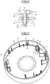
figure 6 représente une coupe partielle agrandie d'un détail du montage d'une antenne sur un doigt du dispositif électronique précité ; - la
figure 7 représente une vue en perspective du côté intérieur d'un couvercle du dispositif électronique précité, équipé d'une antenne ; et - la
figure 8 représente une coupe partielle agrandie d'une variante de réalisation du montage d'une antenne sur un doigt du dispositif électronique précité. - Un dispositif électronique 1 comprend un boîtier 2, par exemple en une matière plastique, composé d'une embase 3 et d'un couvercle 4 qui peuvent être accouplés l'un au-dessus de l'autre par tous moyens d'accouplement appropriés (non représentés), par exemple par encliquetage, et qui, en position accouplée, délimitent entre eux une chambre 5.
- Dans la chambre 5 est installée une carte électronique 6, maintenue en position par exemple par conjugaison de formes.
- La carte électronique 6 présente, en un endroit, un passage traversant 7 recouvert d'une couche 8 en une matière conductrice de l'électricité (
figure 6 ), qui forme un contact électrique et qui est relié au circuit électronique (non représenté) de la carte électronique 6. - Le couvercle 4 comprend un doigt 9 en saillie dans la chambre 5, qui présente une partie d'extrémité ou tête 10 qui peut être engagée librement, avec un jeu, au travers du passage traversant 7 de la carte électronique 6 lorsque l'embase 3 et le couvercle 4 sont accouplés.
- Le couvercle 4 est muni d'une antenne radio ou électromagnétique 11 formée par un fil métallique en une matière élastique et conformée par pliage, par exemple de la manière suivante.
- Comme illustré en particulier sur la
figure 5 , l'antenne préformée 11 comprend une partie d'extrémité 12 qui comprend une portion terminale 13 et une portion en vis-à-vis 14, par exemple rectilignes et reliées par une portion coudée 15 en formant un V, et comprend une portion allongée 16 reliée à la portion en vis-à-vis 14 par une portion 17 se présentant sous la forme d'une spirale. La portion allongée 16 s'étend perpendiculairement ou dans un plan perpendiculaire à l'axe de la portion en spirale 17 et le V formé par la portion terminale 13 et la portion en vis-à-vis 14 est ouvert du côté de la portion en spirale 17. - La longueur de l'antenne 11, c'est-à-dire principalement la longueur de la portion allongée 16 et de la portion en spirale 17, est adaptée à la fréquence de résonnance ou aux fréquences de résonnance souhaitées.
- L'antenne 11 est montée sur le couvercle 4 par conjugaison de formes, c'est-à-dire sans élément complémentaire de fixation, de la manière suivante.
- La portion en spirale 17 est disposée librement autour du doigt en saillie 9.
- Comme illustré en particulier sur la
figure 6 , la partie d'extrémité 12 est montée à cheval sur la tête 10 du doigt en saillie 9, dans le sens de l'axe de ce dernier, de telle sorte que la tête 10 est engagée dans le V formé entre la portion terminale 13 et la portion en vis-à-vis 14. - La tête 10 du doigt en saillie 9 présente une fente latérale de retenue 18 dans laquelle est engagée la portion coudée 15 de l'antenne 11, les flancs opposés de la fente de retenue 18 formant des épaulements de telle sorte que l'antenne 11 est maintenue dans les deux sens selon l'axe de la portion en spirale 17.
- La tête 10 du doigt en saillie 9 présente des flancs opposés parallèles 10a et 10b devant lesquels la portion terminale 13 et la portion en vis-à-vis 14 s'étendent en ménageant des espaces.
- Comme illustré en particulier sur la
figure 7 , la portion allongée 16 s'étend au-dessus d'une paroi 19 du couvercle 4, parallèle à la carte électronique 6, en longeant une paroi cylindrique 20, la partie allongée 16 étant arquée en correspondance. - Le couvercle 4 comprend des parties en saillie 21, espacées, présentant des fentes de maintien 22 dans lesquelles est engagée, latéralement, la portion allongée 16 de l'antenne 11, une fente de maintien étant prévue au pied du doigt en saillie 9.
- Comme illustré en particulier sur les
figures 3 ,4 et7 , pour monter l'antenne 11 sur le couvercle 4, séparé de l'embase 3, il suffit donc de placer la portion en spirale 17 autour du doigt en saillie 9, puis, dans cet ordre ou dans l'autre, d'engager la portion coudée 15 dans la fente de retenue 18 de la tête 10 du doigt en saillie 9 en déformant la partie d'extrémité 12 et d'engager la portion allongée 16 dans les fentes de maintien 22 du couvercle 4, en utilisant l'élasticité du fil métallique. - Ensuite, lorsque l'on approche et que l'on amène l'embase 3 et le couvercle 4 jusqu'à leur position accouplée, la partie d'extrémité 12 de l'antenne 11 s'engage, la pointe du V en premier, au travers du passage 7 de la carte électronique 6, avec la tête 10 du doigt en saillie 9 qui l'entraîne dans le sens de l'introduction du fait que le flanc de la fente de retenue 18 situé du côté de la portion en spirale la tête 10 du doigt en saillie 9 et la portion coudée 15 de la partie d'extrémité 12 sont en appui réciproque. Le doigt en saillie 9 assure le positionnement correct de la partie d'extrémité 12 de l'antenne 11 par rapport au passage 7 de la carte électronique 6.
- Ce faisant, comme illustré sur les
figures 1, 2 et6 , la portion terminale 13 et la portion en vis-à-vis 14 de la partie d'extrémité 12 de l'antenne 11 viennent en appui sur des zones opposées de la couche conductrice 8. L'appui de la portion coudée 15 sur la tête 10 du doigt en saillie 9 étant au-delà de ces zones, la portion terminale 13 et la portion en vis-à-vis 14 glissent sur ces zones, en réduisant l'angle d'ouverture du V que les portions 13 et 14 forment, à l'encontre de l'élasticité du fil métallique formant l'antenne 11 et en bénéficiant de la flexibilité des portions 13 et 14. En fin de course, la portion terminale 13 et la portion en vis-à-vis 14 sont à faibles distances des flancs 10a et 10b de la tête 10 du doigt en saillie 9 qui produit un effet de coincement. - Ainsi, lorsque l'embase 3 et le couvercle 4 sont à leur position accouplée, la portion terminale 13 et la portion en vis-à-vis 14 de la partie d'extrémité 12 de l'antenne 11 sont fermement maintenues en appui sur la couche conductrice 8 et une liaison électrique sécurisée est établie entre l'antenne 11 et le contact électrique formé par cette couche conductrice 8.
- Lorsque l'embase 3 et le couvercle 4 sont séparés, il se produit un mouvement et un effet inverses, la portion coudée 15 de la partie d'extrémité 12 de l'antenne 11 venant en appui sur l'épaulement formé par le flanc de la fente de retenue 18 situé à l'opposé de la portion en spirale 17 de telle sorte que la partie d'extrémité 12 de l'antenne 11 est entraînée dans le sens de son extraction en dehors du passage 7 de la carte électronique.
- Selon une variante de réalisation, la portion en spirale 17 de l'antenne 11 pourrait être remplacée par une portion droite ou arquée.
- Selon une variante de réalisation illustrée sur la
figure 8 , la tête 10 du doigt en saillie 9 pourrait être supprimée. Dans ce cas, l'élasticité du fil formant l'antenne 11 devrait être telle que la portion en spirale 15 ou la portion légèrement arquée pouvant la remplacer produisent un effet de ressort comprimé assurant l'appui de la portion terminale 13 et la portion en vis-à-vis 14 de la partie d'extrémité 12 de l'antenne 11 sur la couche conductrice 8 formant un contact électrique. - Selon une variante de réalisation également illustrée sur la
figure 8 , la partie d'extrémité 12 de l'antenne 11 pourrait présenter une ou des portions coudées venant en appui sur un contact électrique 8a de la face de la carte électronique 6 tournée du côté du couvercle 4, par exemple une portion coudée 13a formée à l'extrémité de la portion terminale 13. - Selon une variante de réalisation, l'antenne 11 pourrait être portée par l'embase 3 de façon équivalente à son montage sur le couvercle 4.
- La présente invention ne se limite pas aux exemples ci-dessus décrits. Bien d'autres variantes de réalisation sont possibles sans sortir du cadre de l'invention.
Claims (9)
- Dispositif électronique comprenant un boîtier (2) dans lequel sont disposées une carte électronique (6) présentant un passage traversant (7) et une antenne (11) comprenant un fil métallique en une matière élastique présentant une partie d'extrémité (12) qui comprend une portion terminale (13) et une portion en vis-à-vis (14), reliées par une portion coudée (15), et qui est engagée au moins partiellement dans ou au travers du passage de la carte électronique,
dans lequel le boîtier (2) et l'antenne (11) comprennent des parties ou portions d'appui réciproque telles que, sous l'effet de l'élasticité du fil métallique, la partie d'extrémité de l'antenne prend appui sur au moins une zone de la carte électronique munie d'un contact électrique (8, 8a) afin d'établir une liaison électrique entre l'antenne et ce contact électrique,
et dans lequel le boîtier (2) comprend un doigt en saillie (9) qui présente une tête (10) de positionnement et de maintien (3, 4 et 51) engagée entre ladite portion terminale (13) et ladite portion en vis-à-vis (14) de ladite partie d'extrémité (12) de l'antenne et coopérant avec cette partie d'extrémité (12) pour assurer l'appui de cette dernière sur ledit contact électrique (8). - Dispositif selon la revendication 1, dans lequel ladite portion terminale et ladite portion en vis-à-vis prennent appui sur des zones opposées dudit passage de la carte électronique dont au moins l'une est munie dudit contact électrique.
- Dispositif selon l'une des revendications 1 et 2, dans lequel le boîtier (2) comprend des moyens de positionnement et de maintien de l'antenne par conjugaison de formes (21).
- Dispositif selon l'une quelconque des revendications précédentes, dans lequel le doigt en saillie est en appui sur ladite partie d'extrémité de l'antenne au moins au-delà de l'une desdites zones opposées dudit passage de la carte électronique.
- Dispositif selon l'une quelconque des revendications précédentes, dans lequel le doigt en saillie présente une fente latérale de retenue (18) dans laquelle est introduite la portion coudée (15) de la partie d'extrémité de l'antenne.
- Dispositif selon l'une quelconque des revendications précédentes, dans lequel le doigt en saillie présente des flancs opposés (10a, 10b) situés respectivement du côté de ladite portion terminale (13) et de ladite portion en vis-à-vis (14) de ladite partie d'extrémité de l'antenne, un espace subsistant entre au moins l'un desdits flancs et la portion correspondante de l'antenne.
- Dispositif selon l'une quelconque des revendications précédentes, dans lequel ladite antenne comprend une partie d'appui (16) sur le support relié à sa partie d'extrémité (12) par une partie déformée (17) produisant un effet de ressort comprimé.
- Dispositif selon l'une quelconque des revendications précédentes, dans lequel l'antenne présente une portion allongée (16) reliée à sa partie d'extrémité, introduite dans au moins une fente de maintien (22) du support.
- Dispositif selon l'une quelconque des revendications précédentes, dans lequel le support comprend une embase (3) et un couvercle (4) pouvant être accouplés, délimitant une chambre (5) dans laquelle la carte électronique (6) est installée, l'un d'entre eux étant muni de l'antenne (11).
Applications Claiming Priority (1)
| Application Number | Priority Date | Filing Date | Title |
|---|---|---|---|
| FR1354459A FR3005793B1 (fr) | 2013-05-17 | 2013-05-17 | Dispositif electronique muni d une antenne radio |
Publications (2)
| Publication Number | Publication Date |
|---|---|
| EP2804255A1 EP2804255A1 (fr) | 2014-11-19 |
| EP2804255B1 true EP2804255B1 (fr) | 2016-04-27 |
Family
ID=48980017
Family Applications (1)
| Application Number | Title | Priority Date | Filing Date |
|---|---|---|---|
| EP14168483.7A Active EP2804255B1 (fr) | 2013-05-17 | 2014-05-15 | Dispositif électronique muni d'une antenne radio |
Country Status (3)
| Country | Link |
|---|---|
| EP (1) | EP2804255B1 (fr) |
| ES (1) | ES2584164T3 (fr) |
| FR (1) | FR3005793B1 (fr) |
Families Citing this family (2)
| Publication number | Priority date | Publication date | Assignee | Title |
|---|---|---|---|---|
| DE102017121899A1 (de) * | 2016-09-22 | 2018-03-22 | Hirschmann Car Communication Gmbh | Kontaktierung zwischen einer Antennenstruktur und einer Leiterplatte |
| EP3685636B1 (fr) | 2017-09-20 | 2024-08-28 | Materion Precision Optics (Shanghai) Limited | Roue à luminophore à liant inorganique |
Family Cites Families (4)
| Publication number | Priority date | Publication date | Assignee | Title |
|---|---|---|---|---|
| US6597326B2 (en) * | 2001-12-21 | 2003-07-22 | Auden Techno Corp. | Structure of helix antenna |
| JP2006081072A (ja) * | 2004-09-13 | 2006-03-23 | Nec Access Technica Ltd | アンテナ及び無線通信端末 |
| FR2913132B1 (fr) * | 2007-02-22 | 2010-05-21 | Somfy Sas | Dispositif de commande radio, actionneur electrique et installation domotique comprenant un tel dispositif |
| US7911397B2 (en) * | 2008-04-02 | 2011-03-22 | Apple Inc. | Antennas for electronic devices |
-
2013
- 2013-05-17 FR FR1354459A patent/FR3005793B1/fr active Active
-
2014
- 2014-05-15 EP EP14168483.7A patent/EP2804255B1/fr active Active
- 2014-05-15 ES ES14168483.7T patent/ES2584164T3/es active Active
Also Published As
| Publication number | Publication date |
|---|---|
| FR3005793A1 (fr) | 2014-11-21 |
| EP2804255A1 (fr) | 2014-11-19 |
| ES2584164T3 (es) | 2016-09-26 |
| FR3005793B1 (fr) | 2016-12-02 |
Similar Documents
| Publication | Publication Date | Title |
|---|---|---|
| EP0860905B1 (fr) | Boítier équipé d'un connecteur pour le raccordement d'une carte à circuit(s) intégré(s) | |
| US9064634B2 (en) | Capacitor holder | |
| FR2787640A1 (fr) | Agencement d'une antenne dans un environnement metallique | |
| FR2787642A1 (fr) | Assemblage de connecteurs electriques | |
| EP2804255A1 (fr) | Dispositif électronique muni d'une antenne radio | |
| JP6871230B2 (ja) | 電気接続箱 | |
| FR3023073A1 (fr) | Borne de connecteur et connecteur comprenant celle-ci | |
| EP2039853B1 (fr) | Ensemble comprenant un poteau de clôture et un boîtier | |
| JP4873655B2 (ja) | 接続ピンと薄板製構成部材との間の電気的な接続のための装置 | |
| EP2980631A1 (fr) | Charnière sans vis de pivot pour monture de lunettes | |
| EP0821837B1 (fr) | Connecteur interrupteur ou inverseur coaxial miniature a plongeur et lames de contact passives | |
| EP3503295B1 (fr) | Boitier antenne pour vehicule automobile | |
| JP2008204725A (ja) | 接続端子 | |
| FR2928786A1 (fr) | Distributeur de faisceaux electriques avec coupelle de protection | |
| EP2575156B1 (fr) | Dispositif anti bâillement prévu pour une zone de jonction de deux portions de coques adjacentes d'un boîtier d'un appareil électrique modulaire. | |
| EP3758166B1 (fr) | Dispositif de connexion électrique | |
| JPWO2013099995A1 (ja) | コネクタ | |
| FR2925822A1 (fr) | Dispositif de connexion d'un element electrique et/ou electronique sur une carte de circuit imprime et element correspondant. | |
| FR2930217A1 (fr) | Dispositif de fixation d'une plaque sur un vehicule automobile et bouclier de vehicule automobile comportant un tel dispositif. | |
| FR2973589A1 (fr) | Connecteur electrique configurable | |
| FR2868159A1 (fr) | Dispositif de montage et d'indexation d'un capteur, detecteur ou analogue | |
| FR2928784A1 (fr) | Dispositif de raccordement electrique notamment pour panneau solaire electrique | |
| FR2733351A1 (fr) | Connecteur interrupteur ou inverseur coaxial miniature a plongeur et lames de contact passives | |
| EP2981159B1 (fr) | Boîtier électronique présentant un socle | |
| FR2483140A1 (fr) | Barre metallique profilee et gaine de conducteur |
Legal Events
| Date | Code | Title | Description |
|---|---|---|---|
| PUAI | Public reference made under article 153(3) epc to a published international application that has entered the european phase |
Free format text: ORIGINAL CODE: 0009012 |
|
| 17P | Request for examination filed |
Effective date: 20140515 |
|
| AK | Designated contracting states |
Kind code of ref document: A1 Designated state(s): AL AT BE BG CH CY CZ DE DK EE ES FI FR GB GR HR HU IE IS IT LI LT LU LV MC MK MT NL NO PL PT RO RS SE SI SK SM TR |
|
| AX | Request for extension of the european patent |
Extension state: BA ME |
|
| R17P | Request for examination filed (corrected) |
Effective date: 20150513 |
|
| GRAJ | Information related to disapproval of communication of intention to grant by the applicant or resumption of examination proceedings by the epo deleted |
Free format text: ORIGINAL CODE: EPIDOSDIGR1 |
|
| GRAP | Despatch of communication of intention to grant a patent |
Free format text: ORIGINAL CODE: EPIDOSNIGR1 |
|
| RIC1 | Information provided on ipc code assigned before grant |
Ipc: H01Q 1/22 20060101ALI20150615BHEP Ipc: H01R 12/71 20110101ALI20150615BHEP Ipc: H05K 3/32 20060101ALI20150615BHEP Ipc: G08B 1/00 20060101ALI20150615BHEP Ipc: H01Q 1/14 20060101ALI20150615BHEP Ipc: H01R 13/24 20060101ALI20150615BHEP Ipc: H01Q 1/08 20060101AFI20150615BHEP |
|
| INTG | Intention to grant announced |
Effective date: 20150717 |
|
| INTC | Intention to grant announced (deleted) | ||
| GRAJ | Information related to disapproval of communication of intention to grant by the applicant or resumption of examination proceedings by the epo deleted |
Free format text: ORIGINAL CODE: EPIDOSDIGR1 |
|
| GRAP | Despatch of communication of intention to grant a patent |
Free format text: ORIGINAL CODE: EPIDOSNIGR1 |
|
| GRAP | Despatch of communication of intention to grant a patent |
Free format text: ORIGINAL CODE: EPIDOSNIGR1 |
|
| INTG | Intention to grant announced |
Effective date: 20151028 |
|
| GRAS | Grant fee paid |
Free format text: ORIGINAL CODE: EPIDOSNIGR3 |
|
| GRAA | (expected) grant |
Free format text: ORIGINAL CODE: 0009210 |
|
| AK | Designated contracting states |
Kind code of ref document: B1 Designated state(s): AL AT BE BG CH CY CZ DE DK EE ES FI FR GB GR HR HU IE IS IT LI LT LU LV MC MK MT NL NO PL PT RO RS SE SI SK SM TR |
|
| REG | Reference to a national code |
Ref country code: GB Ref legal event code: FG4D Free format text: NOT ENGLISH |
|
| REG | Reference to a national code |
Ref country code: CH Ref legal event code: EP |
|
| REG | Reference to a national code |
Ref country code: AT Ref legal event code: REF Ref document number: 795697 Country of ref document: AT Kind code of ref document: T Effective date: 20160515 |
|
| REG | Reference to a national code |
Ref country code: IE Ref legal event code: FG4D Free format text: LANGUAGE OF EP DOCUMENT: FRENCH |
|
| REG | Reference to a national code |
Ref country code: DE Ref legal event code: R096 Ref document number: 602014001651 Country of ref document: DE |
|
| REG | Reference to a national code |
Ref country code: FR Ref legal event code: PLFP Year of fee payment: 3 |
|
| REG | Reference to a national code |
Ref country code: NL Ref legal event code: FP |
|
| REG | Reference to a national code |
Ref country code: LT Ref legal event code: MG4D |
|
| REG | Reference to a national code |
Ref country code: AT Ref legal event code: MK05 Ref document number: 795697 Country of ref document: AT Kind code of ref document: T Effective date: 20160427 |
|
| REG | Reference to a national code |
Ref country code: ES Ref legal event code: FG2A Ref document number: 2584164 Country of ref document: ES Kind code of ref document: T3 Effective date: 20160926 |
|
| PG25 | Lapsed in a contracting state [announced via postgrant information from national office to epo] |
Ref country code: LT Free format text: LAPSE BECAUSE OF FAILURE TO SUBMIT A TRANSLATION OF THE DESCRIPTION OR TO PAY THE FEE WITHIN THE PRESCRIBED TIME-LIMIT Effective date: 20160427 Ref country code: NO Free format text: LAPSE BECAUSE OF FAILURE TO SUBMIT A TRANSLATION OF THE DESCRIPTION OR TO PAY THE FEE WITHIN THE PRESCRIBED TIME-LIMIT Effective date: 20160727 Ref country code: PL Free format text: LAPSE BECAUSE OF FAILURE TO SUBMIT A TRANSLATION OF THE DESCRIPTION OR TO PAY THE FEE WITHIN THE PRESCRIBED TIME-LIMIT Effective date: 20160427 Ref country code: FI Free format text: LAPSE BECAUSE OF FAILURE TO SUBMIT A TRANSLATION OF THE DESCRIPTION OR TO PAY THE FEE WITHIN THE PRESCRIBED TIME-LIMIT Effective date: 20160427 |
|
| PG25 | Lapsed in a contracting state [announced via postgrant information from national office to epo] |
Ref country code: LV Free format text: LAPSE BECAUSE OF FAILURE TO SUBMIT A TRANSLATION OF THE DESCRIPTION OR TO PAY THE FEE WITHIN THE PRESCRIBED TIME-LIMIT Effective date: 20160427 Ref country code: PT Free format text: LAPSE BECAUSE OF FAILURE TO SUBMIT A TRANSLATION OF THE DESCRIPTION OR TO PAY THE FEE WITHIN THE PRESCRIBED TIME-LIMIT Effective date: 20160829 Ref country code: RS Free format text: LAPSE BECAUSE OF FAILURE TO SUBMIT A TRANSLATION OF THE DESCRIPTION OR TO PAY THE FEE WITHIN THE PRESCRIBED TIME-LIMIT Effective date: 20160427 Ref country code: GR Free format text: LAPSE BECAUSE OF FAILURE TO SUBMIT A TRANSLATION OF THE DESCRIPTION OR TO PAY THE FEE WITHIN THE PRESCRIBED TIME-LIMIT Effective date: 20160728 Ref country code: HR Free format text: LAPSE BECAUSE OF FAILURE TO SUBMIT A TRANSLATION OF THE DESCRIPTION OR TO PAY THE FEE WITHIN THE PRESCRIBED TIME-LIMIT Effective date: 20160427 Ref country code: AT Free format text: LAPSE BECAUSE OF FAILURE TO SUBMIT A TRANSLATION OF THE DESCRIPTION OR TO PAY THE FEE WITHIN THE PRESCRIBED TIME-LIMIT Effective date: 20160427 Ref country code: SE Free format text: LAPSE BECAUSE OF FAILURE TO SUBMIT A TRANSLATION OF THE DESCRIPTION OR TO PAY THE FEE WITHIN THE PRESCRIBED TIME-LIMIT Effective date: 20160427 |
|
| REG | Reference to a national code |
Ref country code: DE Ref legal event code: R097 Ref document number: 602014001651 Country of ref document: DE |
|
| PG25 | Lapsed in a contracting state [announced via postgrant information from national office to epo] |
Ref country code: SK Free format text: LAPSE BECAUSE OF FAILURE TO SUBMIT A TRANSLATION OF THE DESCRIPTION OR TO PAY THE FEE WITHIN THE PRESCRIBED TIME-LIMIT Effective date: 20160427 Ref country code: RO Free format text: LAPSE BECAUSE OF FAILURE TO SUBMIT A TRANSLATION OF THE DESCRIPTION OR TO PAY THE FEE WITHIN THE PRESCRIBED TIME-LIMIT Effective date: 20160427 Ref country code: DK Free format text: LAPSE BECAUSE OF FAILURE TO SUBMIT A TRANSLATION OF THE DESCRIPTION OR TO PAY THE FEE WITHIN THE PRESCRIBED TIME-LIMIT Effective date: 20160427 Ref country code: CZ Free format text: LAPSE BECAUSE OF FAILURE TO SUBMIT A TRANSLATION OF THE DESCRIPTION OR TO PAY THE FEE WITHIN THE PRESCRIBED TIME-LIMIT Effective date: 20160427 Ref country code: EE Free format text: LAPSE BECAUSE OF FAILURE TO SUBMIT A TRANSLATION OF THE DESCRIPTION OR TO PAY THE FEE WITHIN THE PRESCRIBED TIME-LIMIT Effective date: 20160427 Ref country code: MC Free format text: LAPSE BECAUSE OF FAILURE TO SUBMIT A TRANSLATION OF THE DESCRIPTION OR TO PAY THE FEE WITHIN THE PRESCRIBED TIME-LIMIT Effective date: 20160427 |
|
| REG | Reference to a national code |
Ref country code: IE Ref legal event code: MM4A |
|
| PG25 | Lapsed in a contracting state [announced via postgrant information from national office to epo] |
Ref country code: SM Free format text: LAPSE BECAUSE OF FAILURE TO SUBMIT A TRANSLATION OF THE DESCRIPTION OR TO PAY THE FEE WITHIN THE PRESCRIBED TIME-LIMIT Effective date: 20160427 |
|
| PLBE | No opposition filed within time limit |
Free format text: ORIGINAL CODE: 0009261 |
|
| STAA | Information on the status of an ep patent application or granted ep patent |
Free format text: STATUS: NO OPPOSITION FILED WITHIN TIME LIMIT |
|
| 26N | No opposition filed |
Effective date: 20170130 |
|
| REG | Reference to a national code |
Ref country code: FR Ref legal event code: PLFP Year of fee payment: 4 |
|
| PG25 | Lapsed in a contracting state [announced via postgrant information from national office to epo] |
Ref country code: IE Free format text: LAPSE BECAUSE OF NON-PAYMENT OF DUE FEES Effective date: 20160515 Ref country code: SI Free format text: LAPSE BECAUSE OF FAILURE TO SUBMIT A TRANSLATION OF THE DESCRIPTION OR TO PAY THE FEE WITHIN THE PRESCRIBED TIME-LIMIT Effective date: 20160427 |
|
| REG | Reference to a national code |
Ref country code: CH Ref legal event code: PL |
|
| PG25 | Lapsed in a contracting state [announced via postgrant information from national office to epo] |
Ref country code: CH Free format text: LAPSE BECAUSE OF NON-PAYMENT OF DUE FEES Effective date: 20170531 Ref country code: LI Free format text: LAPSE BECAUSE OF NON-PAYMENT OF DUE FEES Effective date: 20170531 |
|
| REG | Reference to a national code |
Ref country code: FR Ref legal event code: PLFP Year of fee payment: 5 |
|
| PG25 | Lapsed in a contracting state [announced via postgrant information from national office to epo] |
Ref country code: HU Free format text: LAPSE BECAUSE OF FAILURE TO SUBMIT A TRANSLATION OF THE DESCRIPTION OR TO PAY THE FEE WITHIN THE PRESCRIBED TIME-LIMIT; INVALID AB INITIO Effective date: 20140515 |
|
| PG25 | Lapsed in a contracting state [announced via postgrant information from national office to epo] |
Ref country code: MT Free format text: LAPSE BECAUSE OF FAILURE TO SUBMIT A TRANSLATION OF THE DESCRIPTION OR TO PAY THE FEE WITHIN THE PRESCRIBED TIME-LIMIT Effective date: 20160427 Ref country code: CY Free format text: LAPSE BECAUSE OF FAILURE TO SUBMIT A TRANSLATION OF THE DESCRIPTION OR TO PAY THE FEE WITHIN THE PRESCRIBED TIME-LIMIT Effective date: 20160427 Ref country code: IS Free format text: LAPSE BECAUSE OF FAILURE TO SUBMIT A TRANSLATION OF THE DESCRIPTION OR TO PAY THE FEE WITHIN THE PRESCRIBED TIME-LIMIT Effective date: 20160427 Ref country code: MK Free format text: LAPSE BECAUSE OF FAILURE TO SUBMIT A TRANSLATION OF THE DESCRIPTION OR TO PAY THE FEE WITHIN THE PRESCRIBED TIME-LIMIT Effective date: 20160427 |
|
| PG25 | Lapsed in a contracting state [announced via postgrant information from national office to epo] |
Ref country code: BG Free format text: LAPSE BECAUSE OF FAILURE TO SUBMIT A TRANSLATION OF THE DESCRIPTION OR TO PAY THE FEE WITHIN THE PRESCRIBED TIME-LIMIT Effective date: 20160427 |
|
| PG25 | Lapsed in a contracting state [announced via postgrant information from national office to epo] |
Ref country code: AL Free format text: LAPSE BECAUSE OF FAILURE TO SUBMIT A TRANSLATION OF THE DESCRIPTION OR TO PAY THE FEE WITHIN THE PRESCRIBED TIME-LIMIT Effective date: 20160427 Ref country code: TR Free format text: LAPSE BECAUSE OF FAILURE TO SUBMIT A TRANSLATION OF THE DESCRIPTION OR TO PAY THE FEE WITHIN THE PRESCRIBED TIME-LIMIT Effective date: 20160427 |
|
| REG | Reference to a national code |
Ref country code: NL Ref legal event code: PD Owner name: HAGER SAFETY; FR Free format text: DETAILS ASSIGNMENT: CHANGE OF OWNER(S), MERGE; FORMER OWNER NAME: HAGER SECURITY Effective date: 20230119 |
|
| REG | Reference to a national code |
Ref country code: BE Ref legal event code: PD Owner name: HAGER SAFETY; FR Free format text: DETAILS ASSIGNMENT: CHANGE OF OWNER(S), ASSIGNMENT; FORMER OWNER NAME: HAGER SECURITY Effective date: 20221229 |
|
| REG | Reference to a national code |
Ref country code: LU Ref legal event code: PD Owner name: FINATRAL; FR Free format text: FORMER OWNER: HAGER SECURITY Effective date: 20221230 Ref country code: LU Ref legal event code: HC Owner name: HAGER SAFETY; FR Free format text: FORMER OWNER: HAGER SAFETY Effective date: 20230328 Ref country code: LU Ref legal event code: HC Owner name: HAGER SAFETY; FR Free format text: FORMER OWNER: FINATRAL Effective date: 20221230 |
|
| P01 | Opt-out of the competence of the unified patent court (upc) registered |
Effective date: 20230606 |
|
| P02 | Opt-out of the competence of the unified patent court (upc) changed |
Effective date: 20230712 |
|
| REG | Reference to a national code |
Ref country code: DE Ref legal event code: R081 Ref document number: 602014001651 Country of ref document: DE Owner name: HAGER SAFETY, FR Free format text: FORMER OWNER: HAGER SECURITY, CROLLES, FR |
|
| REG | Reference to a national code |
Ref country code: GB Ref legal event code: 732E Free format text: REGISTERED BETWEEN 20240125 AND 20240131 |
|
| REG | Reference to a national code |
Ref country code: ES Ref legal event code: PC2A Owner name: HAGER SAFETY Effective date: 20240614 |
|
| PGFP | Annual fee paid to national office [announced via postgrant information from national office to epo] |
Ref country code: ES Payment date: 20250602 Year of fee payment: 12 |
|
| PGFP | Annual fee paid to national office [announced via postgrant information from national office to epo] |
Ref country code: LU Payment date: 20260520 Year of fee payment: 13 Ref country code: NL Payment date: 20260520 Year of fee payment: 13 |
|
| PGFP | Annual fee paid to national office [announced via postgrant information from national office to epo] |
Ref country code: GB Payment date: 20260522 Year of fee payment: 13 |
|
| PGFP | Annual fee paid to national office [announced via postgrant information from national office to epo] |
Ref country code: IT Payment date: 20260525 Year of fee payment: 13 |
|
| PGFP | Annual fee paid to national office [announced via postgrant information from national office to epo] |
Ref country code: DE Payment date: 20260522 Year of fee payment: 13 |
|
| PGFP | Annual fee paid to national office [announced via postgrant information from national office to epo] |
Ref country code: BE Payment date: 20260520 Year of fee payment: 13 |
|
| PGFP | Annual fee paid to national office [announced via postgrant information from national office to epo] |
Ref country code: FR Payment date: 20260526 Year of fee payment: 13 |