EP2804098B1 - Gemeinsame Automatisierungssystemsteuerung - Google Patents
Gemeinsame Automatisierungssystemsteuerung Download PDFInfo
- Publication number
- EP2804098B1 EP2804098B1 EP14166370.8A EP14166370A EP2804098B1 EP 2804098 B1 EP2804098 B1 EP 2804098B1 EP 14166370 A EP14166370 A EP 14166370A EP 2804098 B1 EP2804098 B1 EP 2804098B1
- Authority
- EP
- European Patent Office
- Prior art keywords
- application
- automation system
- system controller
- common
- application type
- Prior art date
- Legal status (The legal status is an assumption and is not a legal conclusion. Google has not performed a legal analysis and makes no representation as to the accuracy of the status listed.)
- Active
Links
Images








Classifications
-
- G—PHYSICS
- G05—CONTROLLING; REGULATING
- G05B—CONTROL OR REGULATING SYSTEMS IN GENERAL; FUNCTIONAL ELEMENTS OF SUCH SYSTEMS; MONITORING OR TESTING ARRANGEMENTS FOR SUCH SYSTEMS OR ELEMENTS
- G05B13/00—Adaptive control systems, i.e. systems automatically adjusting themselves to have a performance which is optimum according to some preassigned criterion
- G05B13/02—Adaptive control systems, i.e. systems automatically adjusting themselves to have a performance which is optimum according to some preassigned criterion electric
-
- H—ELECTRICITY
- H04—ELECTRIC COMMUNICATION TECHNIQUE
- H04L—TRANSMISSION OF DIGITAL INFORMATION, e.g. TELEGRAPHIC COMMUNICATION
- H04L12/00—Data switching networks
- H04L12/28—Data switching networks characterised by path configuration, e.g. LAN [Local Area Networks] or WAN [Wide Area Networks]
- H04L12/2803—Home automation networks
Definitions
- This application relates to the field of building systems and, more particularly, to controllers used in a building automation system (BAS).
- BAS building automation system
- Building automation systems encompass a wide variety of systems that aid in the monitoring and control of various aspects of building operation.
- Building automation systems include security systems, fire safety systems, lighting systems, shading systems, and heating, ventilation, and air conditioning (HVAC) systems.
- Lighting systems shading systems, and HVAC systems are sometimes referred to as "environmental control systems” because these systems control the environmental conditions within the building.
- a single facility may include multiple building automation systems (e.g., a security system, a fire system and an environmental control system).
- Multiple building automation systems may be arranged separately from one another or as a single system with a plurality of subsystems that are controlled by a common control station or server.
- the common control station or server may be contained within the building or remote from the building, depending upon the implementation.
- a building automation system control station is the Apogee® Insight® Workstation, available from Siemens Industry, Inc., Building Technologies Division, of Buffalo Grove, IL ("Siemens"), which may be used with the Apogee® building automation system, also available from Siemens.
- Siemens Siemens Industry, Inc.
- Siemens Siemens
- several control stations connected via an Ethernet or another type of network may be distributed throughout one or more building locations, each having the ability to monitor and control system operation.
- the typical building automation system (including those utilizing the Apogee® Insight® Workstation) has a plurality of field panels that are in communication with the central control station. While the central control station is generally used to make modifications and/or changes to one or more of the various components of the building automation system, a field panel may also be operative to allow certain modifications and/or changes to one or more parameters of the system. This typically includes changes to parameters such as temperature and lighting, and/or similar parameters.
- the central control station and field panels are in communication with various field devices, otherwise known as "points".
- Field devices are typically in communication with field panels of building automation systems and are operative to measure, monitor, and/or control various building automation system parameters.
- Example field devices include lights, blinds, thermostats, damper actuators, alarms, HVAC devices, sprinkler systems, speakers, door locks, and numerous other field devices as will be recognized by those of skill in the art. These field devices receive control signals from the central control station and/or field panels. Accordingly, building automation systems are able to control various aspects of building operation by controlling the field devices.
- the nominal schedule also has at least one setpoint associated with each of the time periods.
- the local HVAC controller is configured to accept manual input from a user via a user interface.
- the local HVAC controller is configured to control one or more HVAC units in accordance with the utility pricing operating schedule.
- PLE product line engineering
- Rosenmueller et al., GPCE' 11, October 22-23, 2011, Portland, Oregon, USA discloses adaptive systems to cope with changing requirements for Software Product Lines, whereby tailor-made programs are generated from a common code base and whereby feature binding is accomplished at runtime.
- a field device and field device configuration approach that reduces the number of unique hardware variants and field configurations of field devices by using a common controller and limiting the number of interface variants and the number of housings used with field devices.
- the common controller may be configured in the field with a user interface. Different interface boards may be used with the controller to make a field device for different types of environments and applications, such as voltage, steam, forced air, controlling blinds, etc.
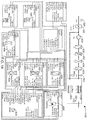
- FIG. 1 An example approach for configuration of field devices is described.
- a system building automation system
- the topology diagram 100 is divided into engineered system 102, installer electronic 104, and installer HVAC, OEM 106.
- the hierarchy of the topology diagram 100 may be divided into operations 108, primary 110, and Room/Zone/FLN 112.
- a network 114 such as a BACnet/IP network, may connect the different control systems and field devices in BAS 100.
- Field devices may include common automation system controllers, such as 116-132. Some of the common automation system controllers may operate building systems such as opening and closing blinds, electrical systems, and HVAC systems.
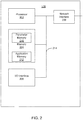
- the common automation system controller 128 may have a processor 202, memory 204, I/O interface 206, and network interface 208 connected by one or more buses 214.
- the processor 202 may be a general purpose microprocessor, microcontroller, application specific processor, reduced instruction set processor, digital logic configured to operate as a state machine, analog circuits configured to operate as a state machine, or a combination of analog and digital circuits operating as a state machine.
- the memory 204 may be static, dynamic or a combination of memory types.
- the memory 204 may be further subdivided into parameter memory 210 and application memory 212.
- the parameter memory 210 may store transient programs and parameters.
- the application memory 212 may store an operating system and other applications that may be permanently resident on the common automation system controller 128.
- the network interface 208 may couple the common automation system controller 128 to a network, such as a BACnet/IP network. Data and control data may be exchanged with other devices in the BAS via the network interface 208.
- the I/O Interface 206 enables control and communication with actuators and sensors.
- the I/O Interface 206 may be implemented as a separate assembly that is coupled to the network interface 208.
- the I/O Interface 206 may also, in some implementations, provide a serial interface for configuring or communication with the common automation system controller 128.
- the network interface 208 may be used for configuring the common automation system controller 128.
- both a serial interface and network interface 208 may be used to communicate with the common automation system controller 128.
- FIG. 3 an exemplary block diagram of the I/O interface 206 of FIG. 2 is depicted.
- the I/O interface 206 may include universal or analog inputs 302 and 304, digital input 306, and relay connections R1 308, R2 310, and R3 312.
- Alternating current (AC) outputs Y1-Y6 314-316 may be directly connected to small fans and other AC devices.
- Analog outputs A01 318 and A02 320 may be used for variable control of devices, such as the speed of a fan or opening of a valve.
- a PL-Link 322 is provided for integration with other field-deployed buses 324 that may enable additional communication with sensors, actuators, and other devices 326.
- different numbers and types of interface connections may be provided for inputting and outputting of data and control signals from the common automation system controller 128 via I/O interface 206.
- FIG. 4 a chart 400 of the levels of engineering flexibility achieved with the use of a common automation system controller, such as common automation system controller 128 of FIG. 1 , is shown.
- Level 1 402 of engineering flexibility is achieved with the use of preloaded applications in the common automation system controller 128.
- preloaded applications By having preloaded applications on the controller, flexibility of I/O may be maintained for configuring different parameters, such as voltage, without affecting the actual performance of the application. Since the applications are not modified, time and resources are saved by not having to test changes prior to implementation of the common automation system controller 128.
- Level 2 404 of engineering flexibility may be achieved by having a library of proven applications where the applications are configurable prior to placement in the common automation system controller 128. Changes to the configured software may require testing, but the starting portion for the configuration is a known working application.
- Level 3 406 of engineering flexibility starts with a proven application from a library, but the functionality of that application is changed or added to. These changes or additions typically require more extensive testing than Level 1204 or Level 2 404. Level 3 406 engineering flexibility also requires more development time as new or additional functionality is being developed.
- Level 4 408 of engineering flexibility has custom or unique applications being employed on the common automation system controller 128. Such custom or unique applications are the most labor intensive level of engineering and often have maintainability issues. Further, such approaches require the most intensive system testing to verify that they will fully function in a BAS. But, there are times where unique customer systems require Level 4 engineering flexibility. Examples of such unique customer systems may include retrofitted BAS to antiquated HVAC systems.
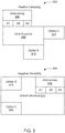
- Diagram 502 depicts positive variability, where additional parts are added to a core structure or application.
- the core structure 506 has alternatives A1, A2, and A3 508. Additionally, options B 510 and C 512 may be added to the core structure.
- Diagram 504 depicts Negative Variability, where the overall structure has parts or modules removed.
- the overall structure 514 may have alternatives A1, A2 A3 516, option B 518 and Option C 520 removed. Both of the variability approaches may be used with the common automation system controller 128.
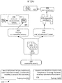
- FIG. 6 a depiction 600 of an approach for implementing structural variability in the configuration of the common automation system controller 128 of FIG. 1 is depicted.
- Static binding 602 of functions at compile time is typically used for applications with negative variability.
- the unnecessary features or optional features are removed prior to or during compiling and loading of the application.
- An application 604 may be created or formed by accessing a library 608 of application types 610.
- the application type 610 is selected and parameterized 612.
- the resulting application 614 may then be compiled and loaded 616.
- the compiling may occur with a graphical object-oriented language in the current example, or in other implementations, programming languages such as C, C++, Java, Visual Basic, Python, or other high level language may be employed.
- the binding may occur during parameterization 612.
- the resulting compiled application 618 may then be loaded onto the common automation system controller, such as common automation system controller 128.
- Dynamic binding 620 may be used to create an application by selecting an application type 604 from a library 608 of application types 610.
- the application type with dynamic binding will typically be pre-loaded 622 in the application memory of a common automation system controller, such as application memory 212 of the common automation system controller 128.
- a common automation system controller such as application memory 212 of the common automation system controller 128.
- the preloaded applications 624 are selected and parameterized with binding of the functions also occurring 626.
- the resulting parameterized or configured application 628 is then executed by the common automation system controller 128.
- the same common automation system controller may be used with negative variability or positive variability.
- FIG. 7 an exemplary diagram 700 of the software 702 and hardware 704 configuration of an application configuration 706 for a common automation system controller 128 of FIG. 1 is depicted.
- the software configuration 702 includes configuring data for control programs, operation & monitoring, and engineering & commissioning functions.
- the software configuration 702 further includes configuring data for the common automation system controller's role (i.e., control blinds, fans, valves, lights) in the BAS 100 and configuring virtual and real interface values for control applications.
- the software configuration 702 may include control programs 708 that originated as an application type in the library 608. Examples of control programs include heating applications, cooling applications, and blind controls to give a few examples.
- the control programs 708 may have parameters that are initially set (i.e., predefined set points), such as analog value set point for heating at 26 degrees Celsius 710 and analog value set point for cooling set to 22 degrees Celsius 712.
- the hardware configuration 704 includes configuring data for peripheral devices, field buses, and data acquisition (such as sensors).
- the hardware configuration data 704 may also include configuring data for supporting sensors, actuators, and networked peripheral devices.
- the hardware configuration 704 may include configuration of outputs and inputs. In the current example, multistate outputs are configured for "Off', "S1", “S2", and “S3" 714 and two sets of analog outputs are configured to have a range of 0 to 100 percent 716 and 718.
- the outputs 714-718 are associated with input and output connections 720-724 on the I/O board that may be connected or coupled to the common automation system controller 128.
- the input and output connections 720-724 may be connected to devices, such as fan 726, heating unit 728, and cooling unit 730.
- the PL-Link network may also be configured to communicate with sensors, such as thermostat 732, supply temperature sensor 734 and exhaust temperature sensors 736 and 738.
- FIG. 8 an exemplary diagram 800 of software programs, modules, or objects for the mechanical equipment of room 802 to be loaded on a common automation system controller 128 of FIG. 1 is depicted.
- the room 802 is shown with four automated blinds 804-810, four lights 812-818, radiator 820, and thermostat 822.
- the room 802 is also supported by HVAC equipment and sensors, such as temperature of outside air sensor 824, outside air damper 826, fan 828, heating coil 830, heating cooling coil 832 (sometimes referred to as a heat transfer coil), cooling coil 834, electric heater 836, supply temperature sensor 840, and return temperature sensor 842.
- the room 802 may be modeled as objects, modules or application types contained in a library.
- the room module 842 that represents the room 802 may have a plurality of sub-modules to support the building automation control of the room 802.
- a room coordination module 844 may have parameters associated with settings for the different devices and sensors in the room 802.
- the fan 828 has an associated fan coil control sub-module 846 that may be configurable for the different types and voltages of fans that may be deployed in a BAS 100.
- Multiple light control sub-modules (light control 848-854) associated with the lights 812-818 are also supported.
- the four automated blinds 804-810 may be associated with blind control sub-modules 856-862. These sub-modules are associated with defining and supporting the configurations of the settings used in the room, such as temperature, light, and energy efficiency of the room 802.
- FIG. 9 an exemplary diagram 900 of software programs, modules, or objects for lighting and blind controls that are further defined for room 802 of FIG. 8 is depicted.
- the light control sub-module 848 associated with lights 812 may have further sub-modules that enable manual operation 902, presence switches (i.e., motion sensor switches) 904, brightness control 908, operating hours 910, Green Leaf operation 912 (energy saving operation parameters) and is associated with brightness control 908.
- the brightness control sub-module 908 may have further configurations or definitions for daylight switch 914, daylight control 916, and constant lighting control 918.
- the blind control sub-module 856 may have further sub-modules that further define the operation of the blinds 804. These blind sub-modules may include Green Leaf operation 920, collision detection 922, manual operation 924, presence operation 926 (i.e., motion sensors), anti-glare protection 928, and energy efficiency 930. Thus, a hierarchical approach for defining library application types is demonstrated.
- Fan coil control 846 has sub-modules for user request 1002, plant control 1004 (a supervisory function that coordinates parts of the BAS 100), and cascade 1006 (function to adjust the temperature at the coils to maintain room temperature). Additionally, the fan coil control 846 also has sub-modules for the outside air damper "OaDmp" 1008, fan 1010, heating coil “Hcl” 1012, heating and cooling coil “HCcl” 1014, Cooling Coil “Ccl” 1016, electric heater “HclEl” 1018, and radiator “Rad” 1020. Thus, sub-modules for sensors and mechanical equipment have been demonstrated.
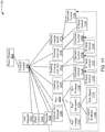
- FIG. 11 an exemplary diagram 1100 of software programs, modules, or objects that further define the hardware and sensors associated with fan coil control 846 is depicted.
- Fan 1010 is further defined for a 1-stage fan 1102, variable speed fan 1104, and n-stage fan 1106.
- the variable speed fan 1104 may be further defined to have fan speed enabled 1108 and reporting for fan speed 1110.
- the heating/cooling coils 1012-1016 and electric heater 1018 may each have temperature controls 1112, 1116, 1120, and 1124, and cascade controls 1114, 1118, 1122, and 1126 that are associated with the cascade sub-module 1006.
- FIG. 12 an exemplary diagram 1200 of a software configuration structure for configuring modules and sub-modules associated with room module representing room 842 of FIG. 8 presented in a graphical user interface is depicted.
- An object 1204 that defines the data and functions for the room is selected and defined to have multiple nodes.
- the object may be a node type 1206 "area" with a node subtype 1208 called "room.”
- Nodes may be defined within the object 1204, such as nodes 1210-1224, which correspond to modules 844-862 and 1202.
- Each of the nodes may have an associated control program, such as 1226-1232 that may be executed within the common automation system controller 128 when it is initialized or otherwise started.
- Each of the nodes may also have additional parameters or data configured, such as 1234-1240.
- FIG. 13 an exemplary diagram 1300 of a software configuration structure for configuring the fan coil 846 of FIG. 8 presented in a graphical interface is depicted.
- An object 1302 of type "functional" 1304 is selected with a node subtype of fan control ("FNC") 1306.
- the object 1302 may have nodes 1308-1319 where each node may also have additional parameters or data configured, such as 1320-1330.
- the outside damper 1308 is an optional element whereas the fan comprises three alternative devices 1102-1106. Either during engineering (i.e., static binding) or at run time (i.e., dynamic binding) respective choices of options and alternatives may be selected.
- the selected functional units will then be auto-connected to the overall fan coil functional unit.
- FIG. 14 an interface chart 1400 of the mechanical equipment for a room 802 of FIG. 8 in accordance with an example implementation is shown.
- the mechanical equipment 820-840 and 1402 is shown with its associated data and control lines. Nodes in the object may represent the mechanical equipment and the nodes associated data flows.
- FIG. 15 an exemplary diagram 1500 of a software configuration structure for the sub-module fan 1010 of fan coil 846 of FIG. 8 presented in a graphical interface is depicted.
- An object 1502 that defines the data and functions for the fan coil is selected and defined to have multiple nodes.
- the object may be a node type 1504 "functional" with a node subtype 1506 called “fancoil.”
- Nodes may be defined within the object 1502, such as nodes 1508-1514 that correspond to modules 1102-1106.
- Each of the nodes may have an associated control program, such as 1516-1520, that may be executed within the common automation system controller 128 when it is initialized or otherwise started. Additionally a fan coil control program may be initiated that is associated with the fan coil control module 846 and object 1502.
- Each of the nodes may also have additional parameters or data configured, such as 1524-1528.
- the fan 1010 has three fan alternatives and during configuration of the common automation system controller 128 (static binding) or at run time (dynamic binding) one of the alternatives may be selected. The selected alternative may then be associated with the coil module or functional unit and respective nested fan sub-modules. Additional sensors and actuators that may have been selected during configuration may also be associated te with the selected fan alternative.
- FIG. 16 an exemplary diagram 1600 of a software configuration structure for multiple room temperatures 1112, 1116, and 1120 of FIG. 11 under the fan coil sub-module 846 presented in a graphical interface is depicted.
- An object 1602 that defines the data and functions for the fan coil is selected and defined to have multiple nodes.
- the object may be a node type 1604 "functional" with a node subtype 1606 called "FNC.”
- Nodes may be defined within the object 1602 or room temperature sensors, such as node 1608 that correspond to modules 1112, 1116, and 1120.
- the RT node 1608 may have additional parameters and data configurations for room temperatures 1610 associated with modules 1112, 1116, and 1120.
- the node 1608 may also be configured to provide output data to other objects, such as analog value object 1612.
- the output data may be associated with the room temperature average 1614.
- the object 1602 is associated with a fan coil control parameters and data 1616, which has another nested control portion 1618 for providing additional parameters and data.
- the room temperature control object 1602 enables one or more room temperature sensors to be added. The sensors may be selected during initial configuration and then employed as a collection object, if an object oriented approach is employed.
- FIG. 17 an exemplary diagram 1700 of a hierarchical structure of the interfaces of the BAS 100 of FIG. 1 is depicted.
- the various objects 1702-1748 associated with the interfaces of a BAS 100 may be organized in a hierarchical structure.
- the aggregated structures may represent different views and navigation paths on various devices in the BAS 100.
- the aggregation enables system functions and infrastructures, networks and subsystems, rooms and supporting systems to have parameters and data grouped together. Aggregation further provides the ability to nest and encapsulate application control modules and nodes. By using such an approach, configuration and handling of data within the BAS 100 becomes more efficient and less prone to errors.
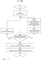
- FIG. 18 a flow diagram 1800 of an approach for the configuration of the common automation system controller 128 of FIG. 1 in accordance with an example implementation is depicted.
- the type to be configured is selected in step 1802.
- One or more application types may be selected for implementation on the common automation system controller 128 from a library 608 of application types in step 1804.
- a determination for static binding or dynamic binding for the selected application types occurs in step 1806. If dynamic binding is employed, then unnecessary parts are removed at initialization or upon starting.
- Objects associated with the BAS 100 and parameters may be configured in step 1808 as the application has previously been loaded on the common automation system controller.
- the selected or used features or modules are selected, parameterized and bound in step 1810.
- the configured application on the common automation system controller 128 starts.
- step 1806 If static binding of the application type is employed in step 1806, then the selected application type is parameterized and bound in step 1814.
- the application type is configured for the BAS using the hierarchical approach in step 1816 and the resulting application is compiled and loaded on the common automation system controller 128 in step 1818.
- step 1812 the configured application on the common automation system controller 128 starts.
- the configuration of the common automation system controller employing dynamic binding may be configured using the preloaded applications.
- the applications may be preloaded prior to deployment at a factory.
- a computer or workstation is typically employed. If static binding is being employed in the configuration of the common automation system controller, a computer or workstation is typically used to initially configure the application types, bind, compile and load the applications.
- a further advantageous embodiment of the invention is a method for configuring a common automation system controller (128), the method comprising:
- a further advantageous embodiment of the invention is a method for configuring a common automation system controller (128), the method comprising:
- a further advantageous embodiment is that the at least one application type (610) employs negative variability (620).
- a further advantageous embodiment is that unnecessary structural parts of the plurality of structural parts are removed during binding (612).
- a further advantageous embodiment is that at least one of the objects for building automation is a fan control object (1606) having a plurality of nodes (610, 1612).
- a further advantageous embodiment is that at least one of the objects for building automation is a heat transfer coil control object (1012) having a plurality of nodes.
- a further advantageous embodiment of the invention is a method for configuring a common automation system controller(128), comprising:
- a further advantageous embodiment is that the at least one application type (624) employs negative variability (620).
- a further advantageous embodiment is that the unnecessary structural parts of the plurality of structural parts are removed (624, 628) during binding (612).
- a further advantageous embodiment is that at least one of the objects (624) for building automation is a fan control object (1606) having a plurality of nodes (1610, 1612).
- At least one of the objects (624) for building automation is a heat transfer coil control object (1012) having a plurality of nodes.
- a further advantageous embodiment of the invention for a non-transient computer-readable medium containing instructions for a method for configuring a common automation system controller (128) is that instructions for binding include instructions for negative variability (620).
- a further advantageous embodiment for the non-transient computer-readable medium containing instructions for a method for configuring a common automation system controller (128) is that instructions for binding (612) include instructions for removal of unnecessary structural parts (628) from the plurality of structural parts (624).
- a further advantageous embodiment for the non-transient computer-readable medium containing instructions for a method for configuring a common automation system controller (128) is that instructions for configuring include instructions for a fan control object (1606) having a plurality of nodes (1610, 1612).
- a further advantageous embodiment for the non-transient computer-readable medium containing instructions for a method for configuring a common automation system controller (128) is that instructions for configuring include instructions for a heat transfer coil control object (1012) having a plurality of nodes.
Landscapes
- Engineering & Computer Science (AREA)
- Automation & Control Theory (AREA)
- Computer Networks & Wireless Communication (AREA)
- Signal Processing (AREA)
- Health & Medical Sciences (AREA)
- Artificial Intelligence (AREA)
- Computer Vision & Pattern Recognition (AREA)
- Evolutionary Computation (AREA)
- Medical Informatics (AREA)
- Software Systems (AREA)
- Physics & Mathematics (AREA)
- General Physics & Mathematics (AREA)
- Programmable Controllers (AREA)
Claims (14)
- Gemeinsame Automatisierungssystemsteuerung (128) umfassend:einen Speicher (204);eine Ein-/Ausgabeschnittstelle (206);eine Bibliothek (608) mit Anwendungstypen, die in dem Speicher (204) gespeichert sind, wobei die Anwendungstypen (604, 610) mit Objekten hierarchisch konfiguriert sind (800), die dem Gebäudeautomatisierungssystem (100) zugeordnet sind, wobei ein oder mehrere Anwendungstypen (604, 610) in der gemeinsamen Automatisierungssystemsteuerung (128) aus der Bibliothek (608) mit Anwendungstypen (604, 610) für die Implementierung ausgewählt werden; undeinen Prozessor (202), der mit dem Speicher (204) gekoppelt und dafür konfiguriert ist, eine Anwendung (604) des ausgewählten Anwendungstyps (610) auszuführen, die Funktionen für ein Gebäudeautomatisierungssystem (100) zugeordnet ist, wobei die Anwendung parametrisiert, kompiliert und in die gemeinsame Systemsteuerung (128) geladen wird (626), wobei die kompilierte Anwendung (628) einer Anwendungsschnittstelle zugeordnet wird, die spezifisch für Funktionen des ausgewählten Anwendungstyps (610) ist, und eine Ein-/Ausgabeschnittstelle (206) mit Einrichtungen des Gebäudeautomatisierungssystems (100) gekoppelt wird.
- Gemeinsame Automatisierungssystemsteuerung (128) nach Anspruch 1, wobei die Anwendungstypen (604, 610) umfassen: a) vorher geladene Anwendungen, die nicht verändert werden (402); b) vorher geladene Anwendungen, die konfigurierbar sind (404); c) bewährte Anwendungen, deren Funktionalität geändert oder hinzugefügt wird (406); und d) individuelle oder einmalige Anwendungen (408).
- Gemeinsame Automatisierungssystemsteuerung (128) nach Anspruch 1, wobei jeder Anwendungstyp (604, 610) eine Netzwerkverbindungskonfiguration (1708) umfasst, die eine Kommunikation mit mindestens einem Sensor (824) ermöglicht.
- Gemeinsame Automatisierungssystemsteuerung (128) nach Anspruch 1, wobei die Ein-/Ausgabeschnittstelle (206) einer Ein-/Ausgabe-Unterbaugruppe (700) zugeordnet ist, die durch den Anwendungstyp (604, 610) definiert ist.
- Gemeinsame Automatisierungssystemsteuerung (128) nach Anspruch 1, wobei der Anwendungstyp (604, 610) eine Hardware-Konfiguration (704) mit Daten für Peripheriegeräte des Gebäudeautomatisierungssystems (100) umfasst.
- Gemeinsame Automatisierungssystemsteuerung (128) nach Anspruch 5, wobei das Peripheriegerät eine Lüftersteuerung ist, definiert als ein Objekt (1602) mit Knoten (1604, 1606), die Daten und Parameter (1608) weiter definieren, die der Lüftersteuerung zugeordnet sind.
- Gemeinsame Automatisierungssystemsteuerung (128) nach Anspruch 1, wobei der Anwendungstyp (604, 610) Software-Konfigurationsdaten (702) für Steuerprogramme, Betriebs- und Überwachungs- sowie Engineering- und Inbetriebnahmefunktionen umfasst.
- Gemeinsame Automatisierungssystemsteuerung (128) nach Anspruch 5, wobei das Peripheriegerät eine Steuerung einer Wärmeübertragungswendel (1012) ist, definiert als ein Objekt (1204) mit Knoten (1206, 1208), die Daten und Parameter weiter definieren, die der Steuerung der Wärmeübertragungswendel (1012) zugeordnet sind.
- Verfahren zum Konfigurieren einer gemeinsamen Automatisierungssystemsteuerung (128), umfassend:Auswählen (1804) zumindest eines Anwendungstyps (604, 610) aus einer Bibliothek (608) mit Anwendungstypen, die in einem Speicher (204) gespeichert sind, wobei die Anwendungstypen (604, 610) mit Objekten hierarchisch konfiguriert sind (800), die dem Gebäudeautomatisierungssystem (100) zugeordnet sind, wobei ein oder mehrere Anwendungstypen (604, 610) in der gemeinsamen Automatisierungssystemsteuerung (128) aus der Bibliothek (608) mit Anwendungstypen (604, 610) für die Implementierung ausgewählt werden;Ermitteln (1806), ob der gewählte Anwendungstyp statische Bindung (602) oder dynamische Bindung (620) verwendet;Laden des zumindest einen ausgewählten Anwendungstyps (604, 610) in einen Speicher (204) der gemeinsamen Automatisierungssystemsteuerung (128) durch einen Prozessor (202), wenn dynamische Bindung (620) ermittelt wird, wobei der zumindest eine ausgewählte Anwendungstyp (604, 610) eine Vielzahl von Funktionen einschließlich einer Anwendungsschnittstelle aufweist;Konfigurieren der Objekte (626) für Gebäudeautomatisierungssysteme und Parameter, die dem zumindest einen Anwendungstyp (604, 610) zugeordnet sind;Binden (626) des zumindest einen ausgewählten Anwendungstyps (604, 610), woraus sich eine ausführbare Anwendung ergibt, die in dem Speicher (204) gespeichert ist, wobei die Anwendungsschnittstelle spezifisch für die verwendeten Funktionen ist; undStarten (1812) mit dem Prozessor (202) der ausführbaren Anwendung, die in dem Speicher (204) gespeichert ist.
- Verfahren nach Anspruch 9, wobei der zumindest eine Anwendungstyp (604, 610) negative Variabilität (504) verwendet.
- Verfahren nach Anspruch 9, wobei unnötige Strukturteile der Vielzahl von Strukturteilen während der Bindung (612) entfernt werden.
- Verfahren nach Anspruch 9, wobei zumindest eines der Objekte (1602) für die Gebäudeautomatisierung ein Lüftersteuerungsobjekt mit einer Vielzahl von Knoten (1604, 1606) ist.
- Verfahren nach Anspruch 9, wobei zumindest eines der Objekte für die Gebäudeautomatisierung ein Wärmeübertragungswendel-Steuerungsobjekt (1204) mit einer Vielzahl von Knoten (1206, 1208) ist.
- Nicht-transientes computerlesbares Medium, das Befehle für ein Verfahren zum Konfigurieren einer gemeinsamen Automatisierungssystemsteuerung (128) enthält, welches Befehle umfasst zum:Laden zumindest eines Anwendungstyps (604, 610) in einen Speicher (204) der gemeinsamen Automatisierungssystemsteuerung (128) durch einen Prozessor (202), wenn dynamische Bindung (620) ermittelt wird, wobei der zumindest eine Anwendungstyp (624) eine Vielzahl von Strukturteilen aufweist, wobei die Anwendungstypen (604, 610) mit Objekten hierarchisch konfiguriert sind (800), die dem Gebäudeautomatisierungssystem (100) zugeordnet sind, wobei ein oder mehrere Anwendungstypen (604, 610) in der gemeinsamen Automatisierungssystemsteuerung (128) aus einer Bibliothek (608) mit Anwendungstypen (604, 610) für die Implementierung ausgewählt werden;Konfigurieren von Objekten für Gebäudeautomatisierungssysteme (100) und Parametern, die dem zumindest einen ausgewählten Anwendungstyp (604, 624) zugeordnet sind, wobei der ausgewählte Anwendungstyp einer Vielzahl von Funktionen und einer Anwendungsschnittstelle zugeordnet ist;Binden (612) des zumindest einen ausgewählten Anwendungstyps, woraus sich eine ausführbare Anwendung (628) ergibt, die in dem Speicher (204) gespeichert ist, mit einer Anwendungsschnittstelle, die spezifisch für die verwendeten Funktionen ist; undStarten (1812) mit dem Prozessor (202) der ausführbaren Anwendung (628), die in dem Speicher (204) gespeichert ist.
Applications Claiming Priority (1)
| Application Number | Priority Date | Filing Date | Title |
|---|---|---|---|
| US13/895,044 US9651924B2 (en) | 2013-05-15 | 2013-05-15 | Common automation system controller |
Publications (2)
| Publication Number | Publication Date |
|---|---|
| EP2804098A1 EP2804098A1 (de) | 2014-11-19 |
| EP2804098B1 true EP2804098B1 (de) | 2019-10-30 |
Family
ID=50721553
Family Applications (1)
| Application Number | Title | Priority Date | Filing Date |
|---|---|---|---|
| EP14166370.8A Active EP2804098B1 (de) | 2013-05-15 | 2014-04-29 | Gemeinsame Automatisierungssystemsteuerung |
Country Status (2)
| Country | Link |
|---|---|
| US (1) | US9651924B2 (de) |
| EP (1) | EP2804098B1 (de) |
Families Citing this family (3)
| Publication number | Priority date | Publication date | Assignee | Title |
|---|---|---|---|---|
| US12333130B2 (en) * | 2016-09-07 | 2025-06-17 | Tyco Fire & Security Gmbh | Systems and methods for visually indicating value changes in a building management system |
| US10794605B2 (en) | 2017-03-10 | 2020-10-06 | Siemens Schweiz Ag | Laboratory ventilation integration |
| US10458672B2 (en) | 2017-12-28 | 2019-10-29 | Siemens Industry, Inc. | Optimized energy usage in an air handling unit |
Family Cites Families (2)
| Publication number | Priority date | Publication date | Assignee | Title |
|---|---|---|---|---|
| WO2008094864A2 (en) * | 2007-01-29 | 2008-08-07 | Johnson Controls Technology Company | System and method for filter creation and use for building automation systems |
| US8538586B2 (en) | 2010-01-22 | 2013-09-17 | Honeywell International Inc. | HVAC control with utility time of day pricing support |
-
2013
- 2013-05-15 US US13/895,044 patent/US9651924B2/en active Active
-
2014
- 2014-04-29 EP EP14166370.8A patent/EP2804098B1/de active Active
Non-Patent Citations (1)
| Title |
|---|
| None * |
Also Published As
| Publication number | Publication date |
|---|---|
| EP2804098A1 (de) | 2014-11-19 |
| US20140343731A1 (en) | 2014-11-20 |
| US9651924B2 (en) | 2017-05-16 |
Similar Documents
| Publication | Publication Date | Title |
|---|---|---|
| EP3201701B1 (de) | Konfiguration eines steuergeräts eines gemeinsamen automationssystems | |
| US9519276B2 (en) | Structure and behavior of a building automation system | |
| US9658607B2 (en) | System, method and apparatus for grouping building automation objects for group communication within a building automation system | |
| CN105793785B (zh) | 用于灵活的房间布置的分组 | |
| US11782410B2 (en) | Building management system with control logic distributed between a virtual controller and a smart edge controller | |
| EP2831680B1 (de) | System und verfahren zur gruppierung von gebäudeautomationsobjekten zur gruppenkommunikation in einem gebäudeautomationssystem | |
| US11940786B2 (en) | Building management system and method with virtual controller and failsafe mode | |
| EP3919991A2 (de) | Verfahren und system zur konfiguration von einem gebäudemanagementsystem | |
| EP3919992A1 (de) | Verfahren und system zur verwaltung von virtuellen steuerungen in einem gebäudemanagementsystem | |
| US10747696B2 (en) | Automatic master-slave system and approach | |
| US8782547B2 (en) | Configurable building control system display | |
| EP2804098B1 (de) | Gemeinsame Automatisierungssystemsteuerung | |
| EP3410238B1 (de) | Gruppierung von aktuatoren in einem gebäudeautomatisierungssystem | |
| US20130238830A1 (en) | Bus extension framework system | |
| Hrmo et al. | The Implementation of a Control System for an Administrative Building Using the KNX Standard | |
| Ricart et al. | How to select a building automation system: Explore the specification of standard, open and proprietary building automation systems. | |
| Rozman et al. | SMART GRID DESIGN FOR EFFICIENT BUILDING MANAGEMENT | |
| BRPI1103407A2 (pt) | sistema microcontrolado ativo para automaÇço residencial e comercial | |
| SK8199Y1 (sk) | Univerzálny programovateľný systém na riadenie a/alebo kontrolu, spôsob nastavenia systému | |
| HK1234505B (zh) | 配置通用自动化系统控制器 | |
| CZ28059U1 (cs) | Volně programovatelný komunikátor |
Legal Events
| Date | Code | Title | Description |
|---|---|---|---|
| PUAI | Public reference made under article 153(3) epc to a published international application that has entered the european phase |
Free format text: ORIGINAL CODE: 0009012 |
|
| 17P | Request for examination filed |
Effective date: 20140429 |
|
| AK | Designated contracting states |
Kind code of ref document: A1 Designated state(s): AL AT BE BG CH CY CZ DE DK EE ES FI FR GB GR HR HU IE IS IT LI LT LU LV MC MK MT NL NO PL PT RO RS SE SI SK SM TR |
|
| AX | Request for extension of the european patent |
Extension state: BA ME |
|
| RAP1 | Party data changed (applicant data changed or rights of an application transferred) |
Owner name: SIEMENS SCHWEIZ AG |
|
| R17P | Request for examination filed (corrected) |
Effective date: 20150420 |
|
| RBV | Designated contracting states (corrected) |
Designated state(s): AL AT BE BG CH CY CZ DE DK EE ES FI FR GB GR HR HU IE IS IT LI LT LU LV MC MK MT NL NO PL PT RO RS SE SI SK SM TR |
|
| STAA | Information on the status of an ep patent application or granted ep patent |
Free format text: STATUS: EXAMINATION IS IN PROGRESS |
|
| 17Q | First examination report despatched |
Effective date: 20181001 |
|
| REG | Reference to a national code |
Ref country code: DE Ref legal event code: R079 Ref document number: 602014055838 Country of ref document: DE Free format text: PREVIOUS MAIN CLASS: G06F0009440000 Ipc: G05B0013020000 |
|
| GRAP | Despatch of communication of intention to grant a patent |
Free format text: ORIGINAL CODE: EPIDOSNIGR1 |
|
| STAA | Information on the status of an ep patent application or granted ep patent |
Free format text: STATUS: GRANT OF PATENT IS INTENDED |
|
| RIC1 | Information provided on ipc code assigned before grant |
Ipc: H04L 12/28 20060101ALI20190618BHEP Ipc: G06F 9/44 20180101ALI20190618BHEP Ipc: G05B 13/02 20060101AFI20190618BHEP |
|
| INTG | Intention to grant announced |
Effective date: 20190716 |
|
| GRAS | Grant fee paid |
Free format text: ORIGINAL CODE: EPIDOSNIGR3 |
|
| GRAA | (expected) grant |
Free format text: ORIGINAL CODE: 0009210 |
|
| STAA | Information on the status of an ep patent application or granted ep patent |
Free format text: STATUS: THE PATENT HAS BEEN GRANTED |
|
| AK | Designated contracting states |
Kind code of ref document: B1 Designated state(s): AL AT BE BG CH CY CZ DE DK EE ES FI FR GB GR HR HU IE IS IT LI LT LU LV MC MK MT NL NO PL PT RO RS SE SI SK SM TR |
|
| REG | Reference to a national code |
Ref country code: GB Ref legal event code: FG4D |
|
| REG | Reference to a national code |
Ref country code: CH Ref legal event code: EP |
|
| REG | Reference to a national code |
Ref country code: CH Ref legal event code: NV Representative=s name: SIEMENS SCHWEIZ AG, CH Ref country code: AT Ref legal event code: REF Ref document number: 1196814 Country of ref document: AT Kind code of ref document: T Effective date: 20191115 |
|
| REG | Reference to a national code |
Ref country code: DE Ref legal event code: R096 Ref document number: 602014055838 Country of ref document: DE |
|
| REG | Reference to a national code |
Ref country code: IE Ref legal event code: FG4D |
|
| REG | Reference to a national code |
Ref country code: SE Ref legal event code: TRGR |
|
| REG | Reference to a national code |
Ref country code: LT Ref legal event code: MG4D |
|
| PG25 | Lapsed in a contracting state [announced via postgrant information from national office to epo] |
Ref country code: ES Free format text: LAPSE BECAUSE OF FAILURE TO SUBMIT A TRANSLATION OF THE DESCRIPTION OR TO PAY THE FEE WITHIN THE PRESCRIBED TIME-LIMIT Effective date: 20191030 Ref country code: PL Free format text: LAPSE BECAUSE OF FAILURE TO SUBMIT A TRANSLATION OF THE DESCRIPTION OR TO PAY THE FEE WITHIN THE PRESCRIBED TIME-LIMIT Effective date: 20191030 Ref country code: LV Free format text: LAPSE BECAUSE OF FAILURE TO SUBMIT A TRANSLATION OF THE DESCRIPTION OR TO PAY THE FEE WITHIN THE PRESCRIBED TIME-LIMIT Effective date: 20191030 Ref country code: GR Free format text: LAPSE BECAUSE OF FAILURE TO SUBMIT A TRANSLATION OF THE DESCRIPTION OR TO PAY THE FEE WITHIN THE PRESCRIBED TIME-LIMIT Effective date: 20200131 Ref country code: NO Free format text: LAPSE BECAUSE OF FAILURE TO SUBMIT A TRANSLATION OF THE DESCRIPTION OR TO PAY THE FEE WITHIN THE PRESCRIBED TIME-LIMIT Effective date: 20200130 Ref country code: LT Free format text: LAPSE BECAUSE OF FAILURE TO SUBMIT A TRANSLATION OF THE DESCRIPTION OR TO PAY THE FEE WITHIN THE PRESCRIBED TIME-LIMIT Effective date: 20191030 Ref country code: FI Free format text: LAPSE BECAUSE OF FAILURE TO SUBMIT A TRANSLATION OF THE DESCRIPTION OR TO PAY THE FEE WITHIN THE PRESCRIBED TIME-LIMIT Effective date: 20191030 Ref country code: BG Free format text: LAPSE BECAUSE OF FAILURE TO SUBMIT A TRANSLATION OF THE DESCRIPTION OR TO PAY THE FEE WITHIN THE PRESCRIBED TIME-LIMIT Effective date: 20200130 Ref country code: NL Free format text: LAPSE BECAUSE OF FAILURE TO SUBMIT A TRANSLATION OF THE DESCRIPTION OR TO PAY THE FEE WITHIN THE PRESCRIBED TIME-LIMIT Effective date: 20191030 Ref country code: PT Free format text: LAPSE BECAUSE OF FAILURE TO SUBMIT A TRANSLATION OF THE DESCRIPTION OR TO PAY THE FEE WITHIN THE PRESCRIBED TIME-LIMIT Effective date: 20200302 |
|
| REG | Reference to a national code |
Ref country code: NL Ref legal event code: MP Effective date: 20191030 |
|
| PG25 | Lapsed in a contracting state [announced via postgrant information from national office to epo] |
Ref country code: HR Free format text: LAPSE BECAUSE OF FAILURE TO SUBMIT A TRANSLATION OF THE DESCRIPTION OR TO PAY THE FEE WITHIN THE PRESCRIBED TIME-LIMIT Effective date: 20191030 Ref country code: RS Free format text: LAPSE BECAUSE OF FAILURE TO SUBMIT A TRANSLATION OF THE DESCRIPTION OR TO PAY THE FEE WITHIN THE PRESCRIBED TIME-LIMIT Effective date: 20191030 Ref country code: IS Free format text: LAPSE BECAUSE OF FAILURE TO SUBMIT A TRANSLATION OF THE DESCRIPTION OR TO PAY THE FEE WITHIN THE PRESCRIBED TIME-LIMIT Effective date: 20200229 |
|
| PG25 | Lapsed in a contracting state [announced via postgrant information from national office to epo] |
Ref country code: AL Free format text: LAPSE BECAUSE OF FAILURE TO SUBMIT A TRANSLATION OF THE DESCRIPTION OR TO PAY THE FEE WITHIN THE PRESCRIBED TIME-LIMIT Effective date: 20191030 |
|
| PG25 | Lapsed in a contracting state [announced via postgrant information from national office to epo] |
Ref country code: CZ Free format text: LAPSE BECAUSE OF FAILURE TO SUBMIT A TRANSLATION OF THE DESCRIPTION OR TO PAY THE FEE WITHIN THE PRESCRIBED TIME-LIMIT Effective date: 20191030 Ref country code: RO Free format text: LAPSE BECAUSE OF FAILURE TO SUBMIT A TRANSLATION OF THE DESCRIPTION OR TO PAY THE FEE WITHIN THE PRESCRIBED TIME-LIMIT Effective date: 20191030 Ref country code: EE Free format text: LAPSE BECAUSE OF FAILURE TO SUBMIT A TRANSLATION OF THE DESCRIPTION OR TO PAY THE FEE WITHIN THE PRESCRIBED TIME-LIMIT Effective date: 20191030 Ref country code: DK Free format text: LAPSE BECAUSE OF FAILURE TO SUBMIT A TRANSLATION OF THE DESCRIPTION OR TO PAY THE FEE WITHIN THE PRESCRIBED TIME-LIMIT Effective date: 20191030 |
|
| REG | Reference to a national code |
Ref country code: DE Ref legal event code: R097 Ref document number: 602014055838 Country of ref document: DE |
|
| PG25 | Lapsed in a contracting state [announced via postgrant information from national office to epo] |
Ref country code: SK Free format text: LAPSE BECAUSE OF FAILURE TO SUBMIT A TRANSLATION OF THE DESCRIPTION OR TO PAY THE FEE WITHIN THE PRESCRIBED TIME-LIMIT Effective date: 20191030 Ref country code: SM Free format text: LAPSE BECAUSE OF FAILURE TO SUBMIT A TRANSLATION OF THE DESCRIPTION OR TO PAY THE FEE WITHIN THE PRESCRIBED TIME-LIMIT Effective date: 20191030 Ref country code: IT Free format text: LAPSE BECAUSE OF FAILURE TO SUBMIT A TRANSLATION OF THE DESCRIPTION OR TO PAY THE FEE WITHIN THE PRESCRIBED TIME-LIMIT Effective date: 20191030 |
|
| PLBE | No opposition filed within time limit |
Free format text: ORIGINAL CODE: 0009261 |
|
| STAA | Information on the status of an ep patent application or granted ep patent |
Free format text: STATUS: NO OPPOSITION FILED WITHIN TIME LIMIT |
|
| 26N | No opposition filed |
Effective date: 20200731 |
|
| PG25 | Lapsed in a contracting state [announced via postgrant information from national office to epo] |
Ref country code: SI Free format text: LAPSE BECAUSE OF FAILURE TO SUBMIT A TRANSLATION OF THE DESCRIPTION OR TO PAY THE FEE WITHIN THE PRESCRIBED TIME-LIMIT Effective date: 20191030 Ref country code: MC Free format text: LAPSE BECAUSE OF FAILURE TO SUBMIT A TRANSLATION OF THE DESCRIPTION OR TO PAY THE FEE WITHIN THE PRESCRIBED TIME-LIMIT Effective date: 20191030 |
|
| PG25 | Lapsed in a contracting state [announced via postgrant information from national office to epo] |
Ref country code: LU Free format text: LAPSE BECAUSE OF NON-PAYMENT OF DUE FEES Effective date: 20200429 |
|
| REG | Reference to a national code |
Ref country code: BE Ref legal event code: MM Effective date: 20200430 |
|
| PG25 | Lapsed in a contracting state [announced via postgrant information from national office to epo] |
Ref country code: BE Free format text: LAPSE BECAUSE OF NON-PAYMENT OF DUE FEES Effective date: 20200430 |
|
| PG25 | Lapsed in a contracting state [announced via postgrant information from national office to epo] |
Ref country code: IE Free format text: LAPSE BECAUSE OF NON-PAYMENT OF DUE FEES Effective date: 20200429 |
|
| PG25 | Lapsed in a contracting state [announced via postgrant information from national office to epo] |
Ref country code: TR Free format text: LAPSE BECAUSE OF FAILURE TO SUBMIT A TRANSLATION OF THE DESCRIPTION OR TO PAY THE FEE WITHIN THE PRESCRIBED TIME-LIMIT Effective date: 20191030 Ref country code: MT Free format text: LAPSE BECAUSE OF FAILURE TO SUBMIT A TRANSLATION OF THE DESCRIPTION OR TO PAY THE FEE WITHIN THE PRESCRIBED TIME-LIMIT Effective date: 20191030 Ref country code: CY Free format text: LAPSE BECAUSE OF FAILURE TO SUBMIT A TRANSLATION OF THE DESCRIPTION OR TO PAY THE FEE WITHIN THE PRESCRIBED TIME-LIMIT Effective date: 20191030 |
|
| PG25 | Lapsed in a contracting state [announced via postgrant information from national office to epo] |
Ref country code: MK Free format text: LAPSE BECAUSE OF FAILURE TO SUBMIT A TRANSLATION OF THE DESCRIPTION OR TO PAY THE FEE WITHIN THE PRESCRIBED TIME-LIMIT Effective date: 20191030 |
|
| REG | Reference to a national code |
Ref country code: AT Ref legal event code: UEP Ref document number: 1196814 Country of ref document: AT Kind code of ref document: T Effective date: 20191030 |
|
| P01 | Opt-out of the competence of the unified patent court (upc) registered |
Effective date: 20230523 |
|
| PGFP | Annual fee paid to national office [announced via postgrant information from national office to epo] |
Ref country code: AT Payment date: 20230307 Year of fee payment: 10 |
|
| REG | Reference to a national code |
Ref country code: AT Ref legal event code: MM01 Ref document number: 1196814 Country of ref document: AT Kind code of ref document: T Effective date: 20240429 |
|
| PG25 | Lapsed in a contracting state [announced via postgrant information from national office to epo] |
Ref country code: AT Free format text: LAPSE BECAUSE OF NON-PAYMENT OF DUE FEES Effective date: 20240429 |
|
| PG25 | Lapsed in a contracting state [announced via postgrant information from national office to epo] |
Ref country code: AT Free format text: LAPSE BECAUSE OF NON-PAYMENT OF DUE FEES Effective date: 20240429 |
|
| PGFP | Annual fee paid to national office [announced via postgrant information from national office to epo] |
Ref country code: DE Payment date: 20250620 Year of fee payment: 12 |
|
| PGFP | Annual fee paid to national office [announced via postgrant information from national office to epo] |
Ref country code: GB Payment date: 20250507 Year of fee payment: 12 |
|
| PGFP | Annual fee paid to national office [announced via postgrant information from national office to epo] |
Ref country code: FR Payment date: 20250411 Year of fee payment: 12 |
|
| PGFP | Annual fee paid to national office [announced via postgrant information from national office to epo] |
Ref country code: SE Payment date: 20250407 Year of fee payment: 12 |
|
| PGFP | Annual fee paid to national office [announced via postgrant information from national office to epo] |
Ref country code: CH Payment date: 20250709 Year of fee payment: 12 |