EP2803971A2 - Particle detecting device and particle detecting method - Google Patents
Particle detecting device and particle detecting method Download PDFInfo
- Publication number
- EP2803971A2 EP2803971A2 EP20140167907 EP14167907A EP2803971A2 EP 2803971 A2 EP2803971 A2 EP 2803971A2 EP 20140167907 EP20140167907 EP 20140167907 EP 14167907 A EP14167907 A EP 14167907A EP 2803971 A2 EP2803971 A2 EP 2803971A2
- Authority
- EP
- European Patent Office
- Prior art keywords
- chamber
- fluid
- flow path
- particles
- adjusting
- Prior art date
- Legal status (The legal status is an assumption and is not a legal conclusion. Google has not performed a legal analysis and makes no representation as to the accuracy of the status listed.)
- Granted
Links
Images


Classifications
-
- G—PHYSICS
- G01—MEASURING; TESTING
- G01N—INVESTIGATING OR ANALYSING MATERIALS BY DETERMINING THEIR CHEMICAL OR PHYSICAL PROPERTIES
- G01N15/00—Investigating characteristics of particles; Investigating permeability, pore-volume or surface-area of porous materials
- G01N15/10—Investigating individual particles
- G01N15/14—Optical investigation techniques, e.g. flow cytometry
- G01N15/1404—Handling flow, e.g. hydrodynamic focusing
-
- G—PHYSICS
- G01—MEASURING; TESTING
- G01N—INVESTIGATING OR ANALYSING MATERIALS BY DETERMINING THEIR CHEMICAL OR PHYSICAL PROPERTIES
- G01N15/00—Investigating characteristics of particles; Investigating permeability, pore-volume or surface-area of porous materials
- G01N15/06—Investigating concentration of particle suspensions
-
- G—PHYSICS
- G01—MEASURING; TESTING
- G01N—INVESTIGATING OR ANALYSING MATERIALS BY DETERMINING THEIR CHEMICAL OR PHYSICAL PROPERTIES
- G01N21/00—Investigating or analysing materials by the use of optical means, i.e. using sub-millimetre waves, infrared, visible or ultraviolet light
- G01N21/17—Systems in which incident light is modified in accordance with the properties of the material investigated
- G01N21/47—Scattering, i.e. diffuse reflection
- G01N21/49—Scattering, i.e. diffuse reflection within a body or fluid
- G01N21/51—Scattering, i.e. diffuse reflection within a body or fluid inside a container, e.g. in an ampoule
-
- G—PHYSICS
- G01—MEASURING; TESTING
- G01N—INVESTIGATING OR ANALYSING MATERIALS BY DETERMINING THEIR CHEMICAL OR PHYSICAL PROPERTIES
- G01N21/00—Investigating or analysing materials by the use of optical means, i.e. using sub-millimetre waves, infrared, visible or ultraviolet light
- G01N21/17—Systems in which incident light is modified in accordance with the properties of the material investigated
- G01N21/47—Scattering, i.e. diffuse reflection
- G01N21/49—Scattering, i.e. diffuse reflection within a body or fluid
- G01N21/53—Scattering, i.e. diffuse reflection within a body or fluid within a flowing fluid, e.g. smoke
-
- G—PHYSICS
- G01—MEASURING; TESTING
- G01N—INVESTIGATING OR ANALYSING MATERIALS BY DETERMINING THEIR CHEMICAL OR PHYSICAL PROPERTIES
- G01N1/00—Sampling; Preparing specimens for investigation
- G01N1/02—Devices for withdrawing samples
- G01N1/22—Devices for withdrawing samples in the gaseous state
- G01N1/2273—Atmospheric sampling
-
- G—PHYSICS
- G01—MEASURING; TESTING
- G01N—INVESTIGATING OR ANALYSING MATERIALS BY DETERMINING THEIR CHEMICAL OR PHYSICAL PROPERTIES
- G01N15/00—Investigating characteristics of particles; Investigating permeability, pore-volume or surface-area of porous materials
- G01N15/06—Investigating concentration of particle suspensions
- G01N15/075—Investigating concentration of particle suspensions by optical means
-
- G—PHYSICS
- G01—MEASURING; TESTING
- G01N—INVESTIGATING OR ANALYSING MATERIALS BY DETERMINING THEIR CHEMICAL OR PHYSICAL PROPERTIES
- G01N21/00—Investigating or analysing materials by the use of optical means, i.e. using sub-millimetre waves, infrared, visible or ultraviolet light
- G01N21/62—Systems in which the material investigated is excited whereby it emits light or causes a change in wavelength of the incident light
- G01N21/63—Systems in which the material investigated is excited whereby it emits light or causes a change in wavelength of the incident light optically excited
- G01N21/64—Fluorescence; Phosphorescence
Definitions
- the present invention relates to an environment evaluating technology, and, in particular, relates to a particle detecting device and particle detecting method.
- An optical particle detecting device draws in air from the room wherein the device is installed, for example, and illuminates the drawn-in air with light.
- a particle that is illuminated with light emits fluorescence or produces scattered light, enabling detection of the numbers, sizes, and the like, of particles included in the air.
- one object of the present invention is to provide a particle detecting device and particle detecting method wherein particles can be detected accurately.
- An aspect of the present disclosure provides a particle detecting device comprising: (a) a frame; (b) a chamber that is disposed within the frame; (c) a sample injection flow path for injecting, into the chamber, a fluid that includes particles, from a first inlet opening that is provided in the frame; (d) an adjusting mechanism for adjusting the state of the fluid within the chamber by supplying a fluid, from which the particles have been removed, into the chamber through an adjusting flow path that connects to the chamber from a second inlet opening that is separate from the first inlet opening that is provided in the frame; and (e) a detecting mechanism for detecting particles included within the fluid, by shining a light into the fluid within the chamber.
- the inventive device includes one, several or all of the following features, in all technically possible combinations:
- an aspect of the present disclosure provides a particle detecting method, including: (a) injecting a fluid that includes particles into a chamber that is disposed within a frame, through a sample injection flow path, from a first inlet opening that is provided within the frame; (b) adjusting the state of the fluid within the chamber by supplying a fluid, from which the particles have been removed, into the chamber through an adjusting flow path that connects to the chamber from a second inlet opening that is separate from the first inlet opening that is provided in the frame; and (c) detecting particles included within the fluid, by shining a light into the fluid within the chamber.
- the inventive method includes one, several or all of the following features, in all technically possible combinations:
- the present invention enables the provision of a particle detecting device and particle detecting method wherein particles can be detected accurately.
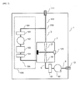
- a particle detecting device as set forth in a first embodiment, as illustrated in FIG. 1 comprises: a frame 1; a chamber 2 that is disposed within the frame 1; an injection nozzle 21 that is disposed within the chamber 2; a sample injection flow path 3 for injecting, into the chamber 2, a fluid that includes particles, connecting between a from a first inlet opening 11 that is provided in the frame 1 and an injection nozzle 21 that is disposed within the chamber 2; an adjusting mechanism 5 for adjusting the state of the fluid within the chamber 2 by supplying a fluid, from which the particles have been removed, into the chamber 2 through an adjusting flow path 4 that connects to the chamber 2 from a second inlet opening 12 that is separate from the first inlet opening 11 that is provided in the frame 1; and a detecting mechanism 23 for detecting particles included within the fluid, by shining a light into the fluid that is blown out from the injection nozzle 21.
- the frame 1 is of an arbitrary shape. Metal, plastic, or the like, may be used as the material for the frame 1, but there is no limitation thereto.
- the shape and material of the chamber 2 are arbitrary. However, preferably the chamber 2 is able to withstand pressure.
- the sample injection flow path 3 is provided with, for example, a pipe made out of metal, plastic, or the like.
- the chamber 2 is provided with a discharge nozzle 22 that opposes the injection nozzle 21. Additionally, an discharge opening 13 is also provided in the frame 1, and a discharge flow path 6, for discharging a fluid from within the chamber 2 to the outside of the frame 1, is provided connecting the discharge nozzle 22 of the chamber 2 and the discharge opening 13 of the frame 1.
- the discharge flow path 6 is provided with a pipe made from, for example, metal or plastic.
- a discharge fan pump 62 is provided as a discharge fan in the discharge flow path 6.
- the fluid that is blown into the chamber 2 is discharged from the chamber 2 through the discharge nozzle 22 that is provided opposing the injection nozzle 21, and then passes through the discharge flow path 6, to be discharged to the outside of the frame 1 from the discharge opening 13 that is provided in the frame 1.
- a light is shined on the flow of the fluid, such as air, or the like, that is formed between the injection nozzle 21 and the discharge nozzle 22, to detect the number of particles included within the fluid through, for example, detecting the scattered light produced by the particles.
- the detecting mechanism 23 may detect the number of particles included in the fluid that is introduced into the chamber 2 through the first inlet opening 11 through detecting fluorescence that is produced by particles included within the fluid.
- the detecting mechanism 23 can calculate the density of particles in the fluid through dividing the number of particles detected per unit time by the volume of fluid that is drawn in through the first inlet opening 11 per unit time.
- microorganisms includes biological substances such as microorganisms, chemical substances, and dust such as dirt, grime, etc.
- microorganisms include bacteria and fungi.
- Gram-negative bacteria and Gram-positive bacteria can be listed as examples of bacteria.
- Escherichia coli for example, can be listed as an example of a Gram-negative bacterium.
- Staphylococcus epidermidis, Bacillus atrophaeus, Micrococcus lylae, and Corynebacterium afermentans can be listed as examples of Gram-positive bacteria.
- Aspergillus species such as Aspergillus niger can be listed as examples of fungi.
- the microorganisms are not limited to these examples.
- a fluorescent particle such as a microorganism
- the particle when illuminated with light, will emit fluorescent light.
- fluorescent light For example, riboflavin, flavin nucleotides (FMN), flavin adenine dinucleotide (FAD), nicotinamide adenine dinucleotide phosphate (NAD(P)H), pyridoxamine, pyridoxal phosphate (pyridoxal-5 '-phosphate), pyridoxine, tryptophan, tyrosine, phenylalanine, and the like, that are included in the microorganisms will produce fluorescence.
- FMN flavin nucleotides
- FAD flavin adenine dinucleotide
- NAD(P)H nicotinamide adenine dinucleotide phosphate
- pyridoxamine pyridoxal phosphate (pyridoxal-5 '-phosphate)
- pyridoxine tryp
- a discharge filter 61 such as a HEPA filter (a High Efficiency Particulate Air filter), or the like, may be provided in the discharge flow path 6.
- the cross-sectional area of the fluid is constricted, increasing the speed of the flow, and decreasing the pressure. Because of this, opposing flows are produced around the flow of the fluid that is formed between the injection nozzle 21 and the discharge nozzle 22. Furthermore, there are cases wherein the discharge of the fluid from the discharge nozzle 22 does not go smoothly because of the drop in pressure within the chamber 2.
- the detecting mechanism 23 may count the same particle multiple times, which may make it difficult to detect accurately the number of particles included in a unit volume of the fluid.
- the particle detecting device is provided with an adjusting mechanism 5 for adjusting the state of the fluid within the chamber 2 by increasing the pressure within the chamber 2, or through rectifying the flow of the fluid in the chamber 2, through providing a fluid, from which particles have been removed, into the chamber 2 through an adjusting flow path 4 that connects to the chamber 2 from a second inlet opening 12 that is separate from the first inlet opening 11 that is provided in the frame 1. This makes it possible to discharge smoothly, from the discharge nozzle 22, the fluid that includes the particles.
- the adjusting flow path 4 is provided with a pipe that is made from metal, plastic, or the like.
- a first filter 51, an adjusting pump 52, a flow meter 53, and a second filter 54, for example, are provided in the adjusting flow path 4.
- the particles that were included in the fluid on the outside of the frame 1, drawn in from the second inlet opening 12 by the adjusting pump 52, are removed by the first filter 51 and the second filter 54.
- the flow meter 53 measures the flow of, for example, the volume of the fluid from which particles have been removed, supplied per unit time to the chamber 2 by the adjusting pump 52.
- a single inlet opening 111 is provided in the frame 1, where the adjusting flow path 104 of the adjusting mechanism 105, and the sample injection flow path 3, are connected to a common flow path 103 that is connected to the single inlet opening 111.
- the adjusting pump 152 draws a portion of the fluid from the common flow path 103 into the adjusting flow path 104, and the particles that are included in the fluid that has been drawn in are removed by the first filter 151 and the second filter 154.
- the fluid from which the particles have been removed is provided to the chamber 2 in order to make adjustments such as increasing the pressure within the chamber 2.
- the detecting mechanism 123 calculates the density of particles in the fluid by dividing the number of particles detected per unit time by the volume of the fluid that is drawn in into the sample injection flow path 3 per unit time. For example, 40 L of the fluid is drawn in per unit time from a single inlet opening 111, where 10 L of the fluid is distributed to the adjusting flow path 104 at a branching point 200, and 30 L of the fluid is distributed to the sample injection flow path 3. In this case, the detecting mechanism 123 calculates the density of particles by dividing the number of particles detected per unit time by the 30 L that is the volume of the fluid that is distributed to the sample injection flow path 3.
- the ratio of the number of particles directed toward the adjusting flow path 104 and the number of particles directed toward the sample injection flow path 3 at the branching points 200 is not necessarily equal to the ratio of the volume of the fluid distributed to the adjusting flow path 104 and the volume of the fluid distributed to the sample injection flow path 3. For example, if 10 L of fluid per unit time is distributed to the adjusting flow path 104 and 30 L per unit time of the fluid is distributed to the sample injection flow path 3, then the ratio of the volume of the fluid distributed to the adjusting flow path 104 to the volume of the fluid distributed to the sample injection flow path 3 is 1:3.
- the common flow path 103 and the sample injection flow path 3 are disposed so as to be on a straight line, than the inertia of the particles will tend to cause a larger number of particles to flow into the sample injection flow path 3 than into the adjusting flow path 104.
- the present inventor discovered that, because of this, when the density of particles in the fluid is calculated by dividing the number of particles detected by the detecting mechanism 123 by the volume of fluid that is distributed to the sample injection flow path 3, the result may be higher than the actual density.
- the adjusting flow path 4 does not branch from the sample injection flow path 3, but rather the fluid that is used for adjusting the pressure within the chamber 2 is drawn in from a second inlet opening 12 that is different from the first inlet opening 11 that is provided in the frame 1. Consequently, the adjusting flow path 4 is independent from the sample injection flow path 3, where the adjusting flow path 4 does not split from the sample injection flow path 3, and thus there will be no error produced even when the density of particles within the fluid is calculated by dividing the number of particles detected per unit time by the detecting mechanism 123 by the volume of the fluid that is drawn in from the first inlet opening 11 per unit time and flows in through the sample injection flow path 3. As a result, the particle detecting device according to the first embodiment enables accurate detection of the number of particles included in the fluid and of the density thereof.
- the adjusting mechanism 5 in the particle detecting device is provided with a compressor 55 for compressing air as the fluid, as illustrated in FIG. 3 .
- the compressed air as the pressurized fluid that is fed from the compressor 55, is sent into the chamber 2 through a first filter 51, a pressure regulator 56, a control valve 57, and a second filter 54.
- the first filter 51, the pressure regulator 56, the control valve 57, and the second filter 54 are provided in an adjusting flow path 4 that passes through a second inlet opening 12.
- a bypass flow path 71 branches from a part 70 between the pressure regulator 56 and the control valve 57 of the adjusting flow path 4, where the bypass flow path 71 joins the discharge flow path 6.
- the first filter 51 and the second filter 54 remove the particles that are included in the compressed air.
- the pressure regulator 56 adjusts the pressure of the compressed air that is provided into the chamber 2.
- the control valve 57 adjusts the allocation ratio between the compressed air that is distributed to the adjusting flow path 4 and the bypass flow path 71.
- An ejector 63 is disposed at the confluence portion of the bypass flow path 71 and the discharge flow path 6.
- the supply of the compressed air from the bypass flow path 71 to the ejector 63 causes the ejector 63 to draw in the fluid from within the chamber 2.
- the particle detecting device according to the second embodiment enables both the supply of compressed air into the chamber 2 and the discharge of air from within the chamber 2 to be performed by the compressor 55, making it possible to simplify the device and reduce the energy consumption.
- the detecting mechanism 23 shown in FIG. 1 and FIG. 3 may measure particles, while airborne, that pass between two laser beams, to calculate the aerodynamic diameters of the particles.
- the present invention should be understood to include a variety of forms of embodiment, and the like, not set forth herein.
Landscapes
- Chemical & Material Sciences (AREA)
- Health & Medical Sciences (AREA)
- General Health & Medical Sciences (AREA)
- Life Sciences & Earth Sciences (AREA)
- Analytical Chemistry (AREA)
- Biochemistry (AREA)
- Physics & Mathematics (AREA)
- General Physics & Mathematics (AREA)
- Immunology (AREA)
- Pathology (AREA)
- Dispersion Chemistry (AREA)
- Investigating Or Analysing Materials By Optical Means (AREA)
- Investigating, Analyzing Materials By Fluorescence Or Luminescence (AREA)
- Sampling And Sample Adjustment (AREA)
- Nuclear Medicine, Radiotherapy & Molecular Imaging (AREA)
Abstract
Description
- The present invention relates to an environment evaluating technology, and, in particular, relates to a particle detecting device and particle detecting method.
- In ordinary rooms or in clean rooms, such as bio clean rooms, airborne particles, including microorganisms, are detected and recorded using particle detecting devices (referencing, for example,
Patent Citations -
- [Patent Citation 1] Japanese Unexamined Patent Application Publication
2008-225539 - [Patent Citation 2] Japanese Unexamined Patent Application Publication
2011-83214 -
- [Non-Patent Citation 1] N. Hasegawa, et al., "Real-time Detecting Technologies for Airborne Microbes, and Applications Thereof," Yamatake Corporation, azbil Technical Review, December 2009, Pages 2-7, 2009
- Given this, one object of the present invention is to provide a particle detecting device and particle detecting method wherein particles can be detected accurately.
- An aspect of the present disclosure provides a particle detecting device comprising: (a) a frame; (b) a chamber that is disposed within the frame; (c) a sample injection flow path for injecting, into the chamber, a fluid that includes particles, from a first inlet opening that is provided in the frame; (d) an adjusting mechanism for adjusting the state of the fluid within the chamber by supplying a fluid, from which the particles have been removed, into the chamber through an adjusting flow path that connects to the chamber from a second inlet opening that is separate from the first inlet opening that is provided in the frame; and (e) a detecting mechanism for detecting particles included within the fluid, by shining a light into the fluid within the chamber.
- According to preferred embodiments, the inventive device includes one, several or all of the following features, in all technically possible combinations:
- the detecting mechanism detects the number of particles per unit volume of fluid that is injected into the chamber from the first inlet opening;
- the adjusting mechanism comprises an adjusting pump for providing the fluid into the chamber; and a filter for removing the particles that are included in the fluid;
- an injection nozzle, disposed within the chamber, connected to the sample injection flow path, a discharge nozzle that is disposed within the chamber, opposing the injection nozzle and a discharge flow path, connecting the discharge nozzle and a discharge opening that is provided within the frame, for discharging, to the outside of the frame, the fluid that is within the chamber;
- a bypass flow path that branches from the adjusting flow path and joins the discharge flow path, wherein an ejector is disposed at the confluence portion of the bypass flow path and the discharge flow path and fluid from within the chamber is drawn by the ejector through provision of pressurized fluid from the bypass flow path to the ejector;
- the adjusting mechanism adjusts the pressure within the chamber;
- the adjusting mechanism rectifies the flow within the chamber;
- the detecting mechanism detects scattered light produced by the particles and/or fluorescent light produced by the particles.
- Furthermore, an aspect of the present disclosure provides a particle detecting method, including: (a) injecting a fluid that includes particles into a chamber that is disposed within a frame, through a sample injection flow path, from a first inlet opening that is provided within the frame; (b) adjusting the state of the fluid within the chamber by supplying a fluid, from which the particles have been removed, into the chamber through an adjusting flow path that connects to the chamber from a second inlet opening that is separate from the first inlet opening that is provided in the frame; and (c) detecting particles included within the fluid, by shining a light into the fluid within the chamber.
- According to preferred embodiments, the inventive method includes one, several or all of the following features, in all technically possible combinations:
- in detecting the particles that are included in the fluid, the number of particles per unit volume of fluid that is injected into the chamber from the first inlet opening is detected;
- an adjusting pump is used in providing a fluid, from which the particles have been removed, into the chamber through the adjusting flow path and a filter for removing the particles is provided in the adjusting flow path;
- disposing an injection nozzle within the chamber, connected to the sample injection flow path and discharging, to the outside of the frame, fluid from within the chamber, through a discharge flow path that connects a discharge opening that is provided in the frame and a discharge nozzle that is provided facing the injection nozzle within the chamber;
- providing a pressurized fluid through an ejector to a bypass flow path that branches from the adjusting flow path and joins the discharge flow path, wherein the ejector draws in fluid from within the chamber;
- in adjusting the state of the fluid within the chamber, the pressure within the chamber is adjusted and/or the flow within the chamber is rectified;
- in detecting the particles, scattered light produced by the particles is detected and/or fluorescent light produced by the particles is detected.
- The present invention enables the provision of a particle detecting device and particle detecting method wherein particles can be detected accurately.
-
-
FIG. 1 is a schematic diagram of a particle detecting device as set forth in a first embodiment according to the present disclosure. -
FIG. 2 is a schematic diagram of a particle detecting device according to a comparative example in the present disclosure. -
FIG. 3 is a schematic diagram of a particle detecting device as set forth in a second embodiment according to the present disclosure. - Forms of embodiment of the present invention will be described below. In the descriptions of the drawings below, identical or similar components are indicated by identical or similar codes. Note that the diagrams are schematic. Consequently, specific measurements should be evaluated in light of the descriptions below. Furthermore, even within these drawings there may, of course, be portions having differing dimensional relationships and proportions.
- A particle detecting device as set forth in a first embodiment, as illustrated in
FIG. 1 , comprises: aframe 1; achamber 2 that is disposed within theframe 1; aninjection nozzle 21 that is disposed within thechamber 2; a sampleinjection flow path 3 for injecting, into thechamber 2, a fluid that includes particles, connecting between a from a first inlet opening 11 that is provided in theframe 1 and aninjection nozzle 21 that is disposed within thechamber 2; anadjusting mechanism 5 for adjusting the state of the fluid within thechamber 2 by supplying a fluid, from which the particles have been removed, into thechamber 2 through an adjustingflow path 4 that connects to thechamber 2 from a second inlet opening 12 that is separate from the first inlet opening 11 that is provided in theframe 1; and adetecting mechanism 23 for detecting particles included within the fluid, by shining a light into the fluid that is blown out from theinjection nozzle 21. - The
frame 1 is of an arbitrary shape. Metal, plastic, or the like, may be used as the material for theframe 1, but there is no limitation thereto. The shape and material of thechamber 2 are arbitrary. However, preferably thechamber 2 is able to withstand pressure. The sampleinjection flow path 3 is provided with, for example, a pipe made out of metal, plastic, or the like. - The
chamber 2 is provided with adischarge nozzle 22 that opposes theinjection nozzle 21. Additionally, andischarge opening 13 is also provided in theframe 1, and adischarge flow path 6, for discharging a fluid from within thechamber 2 to the outside of theframe 1, is provided connecting thedischarge nozzle 22 of thechamber 2 and thedischarge opening 13 of theframe 1. Thedischarge flow path 6 is provided with a pipe made from, for example, metal or plastic. Adischarge fan pump 62 is provided as a discharge fan in thedischarge flow path 6. - The fluid, such as air, or the like, from the outside of the
frame 1, that has been drawn in by thedischarge fan pump 62 through the first inlet opening 11 of theframe 1, is blown into thechamber 2 through the sampleinjection flow path 3 and theinjection nozzle 21. The fluid that is blown into thechamber 2 is discharged from thechamber 2 through thedischarge nozzle 22 that is provided opposing theinjection nozzle 21, and then passes through thedischarge flow path 6, to be discharged to the outside of theframe 1 from thedischarge opening 13 that is provided in theframe 1. - In the
detecting mechanism 23, a light is shined on the flow of the fluid, such as air, or the like, that is formed between theinjection nozzle 21 and thedischarge nozzle 22, to detect the number of particles included within the fluid through, for example, detecting the scattered light produced by the particles. Conversely, thedetecting mechanism 23 may detect the number of particles included in the fluid that is introduced into thechamber 2 through the first inlet opening 11 through detecting fluorescence that is produced by particles included within the fluid. Moreover, thedetecting mechanism 23 can calculate the density of particles in the fluid through dividing the number of particles detected per unit time by the volume of fluid that is drawn in through the first inlet opening 11 per unit time. - Here "particles" includes biological substances such as microorganisms, chemical substances, and dust such as dirt, grime, etc. Examples of microorganisms include bacteria and fungi. Gram-negative bacteria and Gram-positive bacteria can be listed as examples of bacteria. Escherichia coli, for example, can be listed as an example of a Gram-negative bacterium. Staphylococcus epidermidis, Bacillus atrophaeus, Micrococcus lylae, and Corynebacterium afermentans can be listed as examples of Gram-positive bacteria. Aspergillus species such as Aspergillus niger can be listed as examples of fungi. However, the microorganisms are not limited to these examples.
- When a fluorescent particle, such as a microorganism, is included, the particle, when illuminated with light, will emit fluorescent light. For example, riboflavin, flavin nucleotides (FMN), flavin adenine dinucleotide (FAD), nicotinamide adenine dinucleotide phosphate (NAD(P)H), pyridoxamine, pyridoxal phosphate (pyridoxal-5 '-phosphate), pyridoxine, tryptophan, tyrosine, phenylalanine, and the like, that are included in the microorganisms will produce fluorescence.
- For example, if the particle detecting device is disposed in a clean room, or the like, it may be undesirable for particles to be included in the flow that is discharged to the outside of the
frame 1 through thedischarge opening 13 that is provided in theframe 1. In such a case, adischarge filter 61, such as a HEPA filter (a High Efficiency Particulate Air filter), or the like, may be provided in thedischarge flow path 6. - In the
injection nozzle 21 of thechamber 2, the cross-sectional area of the fluid is constricted, increasing the speed of the flow, and decreasing the pressure. Because of this, opposing flows are produced around the flow of the fluid that is formed between theinjection nozzle 21 and thedischarge nozzle 22. Furthermore, there are cases wherein the discharge of the fluid from thedischarge nozzle 22 does not go smoothly because of the drop in pressure within thechamber 2. When opposing flows are produced within thechamber 2 or when there is a pressure drop within thechamber 2, particles may remain stagnant within thechamber 2. When particles remain stagnant within thechamber 2, then the detectingmechanism 23 may count the same particle multiple times, which may make it difficult to detect accurately the number of particles included in a unit volume of the fluid. - In contrast, the particle detecting device according to the first embodiment is provided with an
adjusting mechanism 5 for adjusting the state of the fluid within thechamber 2 by increasing the pressure within thechamber 2, or through rectifying the flow of the fluid in thechamber 2, through providing a fluid, from which particles have been removed, into thechamber 2 through an adjustingflow path 4 that connects to thechamber 2 from a second inlet opening 12 that is separate from the first inlet opening 11 that is provided in theframe 1. This makes it possible to discharge smoothly, from thedischarge nozzle 22, the fluid that includes the particles. - The adjusting
flow path 4 is provided with a pipe that is made from metal, plastic, or the like. Afirst filter 51, an adjustingpump 52, aflow meter 53, and asecond filter 54, for example, are provided in the adjustingflow path 4. The particles that were included in the fluid on the outside of theframe 1, drawn in from the second inlet opening 12 by the adjustingpump 52, are removed by thefirst filter 51 and thesecond filter 54. Theflow meter 53 measures the flow of, for example, the volume of the fluid from which particles have been removed, supplied per unit time to thechamber 2 by the adjustingpump 52. - Here, in a reference example of the present disclosure, as illustrated in
FIG. 2 , asingle inlet opening 111 is provided in theframe 1, where the adjustingflow path 104 of theadjusting mechanism 105, and the sampleinjection flow path 3, are connected to acommon flow path 103 that is connected to thesingle inlet opening 111. The adjustingpump 152 draws a portion of the fluid from thecommon flow path 103 into the adjustingflow path 104, and the particles that are included in the fluid that has been drawn in are removed by thefirst filter 151 and thesecond filter 154. The fluid from which the particles have been removed is provided to thechamber 2 in order to make adjustments such as increasing the pressure within thechamber 2. - The detecting
mechanism 123 calculates the density of particles in the fluid by dividing the number of particles detected per unit time by the volume of the fluid that is drawn in into the sampleinjection flow path 3 per unit time. For example, 40 L of the fluid is drawn in per unit time from asingle inlet opening 111, where 10 L of the fluid is distributed to the adjustingflow path 104 at a branchingpoint 200, and 30 L of the fluid is distributed to the sampleinjection flow path 3. In this case, the detectingmechanism 123 calculates the density of particles by dividing the number of particles detected per unit time by the 30 L that is the volume of the fluid that is distributed to the sampleinjection flow path 3. - However, the ratio of the number of particles directed toward the adjusting
flow path 104 and the number of particles directed toward the sampleinjection flow path 3 at the branchingpoints 200 is not necessarily equal to the ratio of the volume of the fluid distributed to the adjustingflow path 104 and the volume of the fluid distributed to the sampleinjection flow path 3. For example, if 10 L of fluid per unit time is distributed to the adjustingflow path 104 and 30 L per unit time of the fluid is distributed to the sampleinjection flow path 3, then the ratio of the volume of the fluid distributed to the adjustingflow path 104 to the volume of the fluid distributed to the sampleinjection flow path 3 is 1:3. However, at the branchingpoint 200, if thecommon flow path 103 and the sampleinjection flow path 3 are disposed so as to be on a straight line, than the inertia of the particles will tend to cause a larger number of particles to flow into the sampleinjection flow path 3 than into the adjustingflow path 104. The present inventor discovered that, because of this, when the density of particles in the fluid is calculated by dividing the number of particles detected by the detectingmechanism 123 by the volume of fluid that is distributed to the sampleinjection flow path 3, the result may be higher than the actual density. - In contrast, in the particle detecting device according to the first embodiment, illustrated in
FIG. 1 , the adjustingflow path 4 does not branch from the sampleinjection flow path 3, but rather the fluid that is used for adjusting the pressure within thechamber 2 is drawn in from a second inlet opening 12 that is different from the first inlet opening 11 that is provided in theframe 1. Consequently, the adjustingflow path 4 is independent from the sampleinjection flow path 3, where the adjustingflow path 4 does not split from the sampleinjection flow path 3, and thus there will be no error produced even when the density of particles within the fluid is calculated by dividing the number of particles detected per unit time by the detectingmechanism 123 by the volume of the fluid that is drawn in from the first inlet opening 11 per unit time and flows in through the sampleinjection flow path 3. As a result, the particle detecting device according to the first embodiment enables accurate detection of the number of particles included in the fluid and of the density thereof. - The
adjusting mechanism 5 in the particle detecting device according to a second embodiment is provided with acompressor 55 for compressing air as the fluid, as illustrated inFIG. 3 . The compressed air, as the pressurized fluid that is fed from thecompressor 55, is sent into thechamber 2 through afirst filter 51, apressure regulator 56, acontrol valve 57, and asecond filter 54. Thefirst filter 51, thepressure regulator 56, thecontrol valve 57, and thesecond filter 54 are provided in an adjustingflow path 4 that passes through a second inlet opening 12. - A
bypass flow path 71 branches from apart 70 between thepressure regulator 56 and thecontrol valve 57 of the adjustingflow path 4, where thebypass flow path 71 joins thedischarge flow path 6. Thefirst filter 51 and thesecond filter 54 remove the particles that are included in the compressed air. Thepressure regulator 56 adjusts the pressure of the compressed air that is provided into thechamber 2. Thecontrol valve 57 adjusts the allocation ratio between the compressed air that is distributed to the adjustingflow path 4 and thebypass flow path 71. - An
ejector 63 is disposed at the confluence portion of thebypass flow path 71 and thedischarge flow path 6. The supply of the compressed air from thebypass flow path 71 to theejector 63 causes theejector 63 to draw in the fluid from within thechamber 2. The particle detecting device according to the second embodiment enables both the supply of compressed air into thechamber 2 and the discharge of air from within thechamber 2 to be performed by thecompressor 55, making it possible to simplify the device and reduce the energy consumption. - While there are descriptions of forms of embodiment as set forth above, the descriptions and drawings that form a portion of the disclosure are not to be understood to limit the present invention. A variety of alternate examples of embodiment and operating technologies should be obvious to those skilled in the art. For example, the detecting
mechanism 23 shown inFIG. 1 andFIG. 3 may measure particles, while airborne, that pass between two laser beams, to calculate the aerodynamic diameters of the particles. In this way, the present invention should be understood to include a variety of forms of embodiment, and the like, not set forth herein. -
- 1: Frame
- 2: Chamber
- 3: Sample Injection Flow Path
- 4: Adjusting Flow Path
- 5: Adjusting Mechanism
- 6: Discharge Flow Path
- 11: First Inlet Opening
- 12: Second Inlet Opening
- 13: Discharge Opening
- 21: Injection Nozzle
- 22: Discharge Nozzle
- 23: Detecting Mechanism
- 51: First Filter
- 52: Adjusting Pump
- 53: Flow Meter
- 54: Second Filter
- 55: Compressor
- 56: Pressure Regulator
- 57: Control Valve
- 61: Discharge Filter
- 62: Discharge Pump
- 63: Ejector
- 70: Part
- 71: Bypass Flow Path
- 103: Common Flow Path
- 104: Adjusting Flow Path
- 105: Adjusting Mechanism
- 111: Inlet Opening
- 123: Detecting Mechanism
- 151: First Filter
- 152: Adjusting Pump
- 154: Second Filter
- 200: Branching Point
Claims (15)
- A particle detecting device comprising:a frame (1);a chamber (2) that is disposed within the frame (1);a sample injection flow path (3) for injecting, into the chamber (2), a fluid that includes particles, from a first inlet opening (11) that is provided in the frame (1);an adjusting mechanism (5) for adjusting the state of the fluid within the chamber (2) by supplying a fluid, from which the particles have been removed, into the chamber (2) through an adjusting flow path (4) that connects to the chamber (2) from a second inlet opening (12) that is separate from the first inlet opening (11) that is provided in the frame (1); anda detecting mechanism (23) for detecting particles included within the fluid, by shining a light into the fluid within the chamber (2).
- A particle detecting device as set forth in Claim 1, wherein:the detecting mechanism (23) detects the number of particles per unit volume of fluid that is injected into the chamber (2) from the first inlet opening (11).
- A particle detecting device as set forth in Claim 1 or Claim 2, wherein:
the adjusting mechanism (5) comprises:an adjusting pump (52) for providing the fluid into the chamber (2); anda filter (51) for removing the particles that are included in the fluid. - A particle detecting device as set forth in any one of Claim 1 through Claim 3, further comprising:an injection nozzle (21), disposed within the chamber (2), connected to the sample injection flow path (3);a discharge nozzle (22) that is disposed within the chamber (2), opposing the injection nozzle (21); anda discharge flow path (6), connecting the discharge nozzle (22) and a discharge opening (13) that is provided within the frame (1), for discharging, to the outside of the frame (1), the fluid that is within the chamber (2).
- A particle detecting device as set forth in Claim 4, further comprising:a bypass flow path (71) that branches from the adjusting flow path (4) and joins the discharge flow path (6), wherein:an ejector (63) is disposed at the confluence portion of the bypass flow path (71) and the discharge flow path (6); andfluid from within the chamber (2) is drawn by the ejector (63) through provision of pressurized fluid from the bypass flow path (71) to the ejector (63).
- A particle detecting device as set forth in any one of Claim 1 through Claim 5, wherein:the adjusting mechanism (5) adjusts the pressure within the chamber (2).
- A particle detecting device as set forth in any one of Claim 1 through Claim 6, wherein:
the adjusting mechanism (5) rectifies the flow within the chamber (2). - A particle detecting device as set forth in any one of Claim 1 through Claim 7, wherein:the detecting mechanism (23) detects scattered light produced by the particles and/or fluorescent light produced by the particles.
- A particle detecting method, including:injecting a fluid that includes particles into a chamber (2) that is disposed within a frame (1), through a sample injection flow path (3), from a first inlet opening (11) that is provided within the frame (1);adjusting the state of the fluid within the chamber (2) by supplying a fluid, from which the particles have been removed, into the chamber (2) through an adjusting flow path (4) that connects to the chamber (2) from a second inlet opening (12) that is separate from the first inlet opening (11) that is provided in the frame (1); anddetecting particles included within the fluid, by shining a light into the fluid within the chamber (2).
- A particle detecting method as set forth in Claim 9, wherein:in detecting the particles that are included in the fluid, the number of particles per unit volume of fluid that is injected into the chamber (2) from the first inlet opening (11) is detected.
- A particle detecting method as set forth in Claim 9 or Claim 10, wherein:an adjusting pump (52) is used in providing a fluid, from which the particles have been removed, into the chamber (2) through the adjusting flow path (4); anda filter (51) for removing the particles is provided in the adjusting flow path (4).
- A particle detecting method as set forth in any one of Claim 9 through Claim 11, further including:disposing an injection nozzle (21) within the chamber (2), connected to the sample injection flow path (3); anddischarging, to the outside of the frame (1), fluid from within the chamber (2), through a discharge flow path (6) that connects a discharge opening (13) that is provided in the frame (1) and a discharge nozzle (22) that is provided facing the injection nozzle (21) within the chamber (2).
- A particle detecting method as set forth in Claim 12, further including:providing a pressurized fluid through an ejector (63) to a bypass flow path (71) that branches from the adjusting flow path (4) and joins the discharge flow path (6), wherein: the ejector (63) draws in fluid from within the chamber (2).
- A particle detecting method as set forth in any one of Claim 9 through Claim 13, wherein:in adjusting the state of the fluid within the chamber (2), the pressure within the chamber (2) is adjusted and/orthe flow within the chamber (2) is rectified.
- A particle detecting method as set forth in any one of Claim 9 through Claim 14, wherein:in detecting the particles, scattered light produced by the particles is detectedand/or fluorescent light produced by the particles is detected.
Applications Claiming Priority (1)
| Application Number | Priority Date | Filing Date | Title |
|---|---|---|---|
| JP2013105318A JP2014228276A (en) | 2013-05-17 | 2013-05-17 | Particle detection device and particle detection method |
Publications (3)
| Publication Number | Publication Date |
|---|---|
| EP2803971A2 true EP2803971A2 (en) | 2014-11-19 |
| EP2803971A3 EP2803971A3 (en) | 2015-01-28 |
| EP2803971B1 EP2803971B1 (en) | 2019-06-26 |
Family
ID=50729362
Family Applications (1)
| Application Number | Title | Priority Date | Filing Date |
|---|---|---|---|
| EP14167907.6A Active EP2803971B1 (en) | 2013-05-17 | 2014-05-12 | Particle detecting device and particle detecting method |
Country Status (3)
| Country | Link |
|---|---|
| US (1) | US9297740B2 (en) |
| EP (1) | EP2803971B1 (en) |
| JP (1) | JP2014228276A (en) |
Families Citing this family (8)
| Publication number | Priority date | Publication date | Assignee | Title |
|---|---|---|---|---|
| JP6456605B2 (en) * | 2014-05-28 | 2019-01-23 | アズビル株式会社 | Particle detector |
| JP6475069B2 (en) * | 2015-04-23 | 2019-02-27 | アズビル株式会社 | Particle detection apparatus and particle detection method |
| JP6714441B2 (en) | 2016-06-09 | 2020-06-24 | アズビル株式会社 | Particle detecting device and method of controlling particle detecting device |
| EP3258241B1 (en) | 2017-09-14 | 2019-12-25 | Sensirion AG | Particulate matter sensor device |
| WO2019201449A1 (en) * | 2018-04-20 | 2019-10-24 | Flo2R Aps | Gas analyser system |
| CN109406326A (en) * | 2018-12-26 | 2019-03-01 | 内蒙古工业大学 | The detection system of abrasion test device and mechanical part |
| JP7851777B2 (en) * | 2022-04-22 | 2026-04-27 | Ckd株式会社 | Particle detection device |
| JP2024139276A (en) * | 2023-03-27 | 2024-10-09 | Ckd株式会社 | Particle Detector |
Citations (2)
| Publication number | Priority date | Publication date | Assignee | Title |
|---|---|---|---|---|
| JP2008225539A (en) | 2007-03-08 | 2008-09-25 | Nohmi Bosai Ltd | Smoke sensor |
| JP2011083214A (en) | 2009-10-14 | 2011-04-28 | Sharp Corp | Microorganism detection apparatus and detection method |
Family Cites Families (22)
| Publication number | Priority date | Publication date | Assignee | Title |
|---|---|---|---|---|
| FR1529083A (en) * | 1966-07-16 | 1968-06-14 | Scholven Chemie Ag | Sample divider device for gas analyzers |
| DE1673068B2 (en) | 1966-07-16 | 1976-07-01 | Veba-Chemie Ag, 4660 Gelsenkirchen-Buer | DEVICE FOR APPLYING A GAS ANALYZER, IN PARTICULAR A GAS CHROMATOGRAPH, WITH A PARTIAL QUANTITY OF A MAIN GAS FLOW |
| US3787122A (en) * | 1973-01-05 | 1974-01-22 | Wehr Corp | Light scattering particle analyzer |
| US4113386A (en) * | 1976-09-20 | 1978-09-12 | Climet Instruments Company | Photometer |
| JPS61278734A (en) * | 1985-06-03 | 1986-12-09 | Hitachi Electronics Eng Co Ltd | Corpuscle detecting device |
| US5245405A (en) * | 1990-05-11 | 1993-09-14 | Boc Health Care, Inc. | Constant pressure gas cell |
| JP2944021B2 (en) * | 1993-11-17 | 1999-08-30 | 日立電子エンジニアリング株式会社 | Particle detector |
| JP3258881B2 (en) * | 1995-11-24 | 2002-02-18 | 株式会社堀場製作所 | Dry particle size distribution analyzer |
| JP3403564B2 (en) * | 1995-12-04 | 2003-05-06 | 日機装株式会社 | Powder particle size distribution analyzer |
| US6211956B1 (en) * | 1998-10-15 | 2001-04-03 | Particle Sizing Systems, Inc. | Automatic dilution system for high-resolution particle size analysis |
| AU4577900A (en) * | 1999-04-20 | 2000-11-02 | Secretary Of State For Defence, The | Apparatus to detect shape, size and fluorescence of fluidborne particles |
| FR2810098B1 (en) * | 2000-06-13 | 2004-04-23 | Inst Francais Du Petrole | VISUALIZATION DEVICE ADAPTABLE TO A PIPELINE OR FLUID LOADED WITH SOLID PARTICLES |
| US6714299B2 (en) * | 2001-07-13 | 2004-03-30 | Genicon Sciences Corporation | Use of light scattering particles in design, manufacture, and quality control of small volume instruments, devices, and processes |
| JP2003156428A (en) * | 2001-11-21 | 2003-05-30 | Hitachi Electronics Eng Co Ltd | Particle detector |
| JP2005308414A (en) * | 2004-04-16 | 2005-11-04 | Meisei Electric Co Ltd | Floating substance detector |
| GB0421469D0 (en) * | 2004-09-27 | 2004-10-27 | Dt Assembly & Test Europ Ltd | Apparatus for monitoring engine exhaust |
| US7300631B2 (en) * | 2005-05-02 | 2007-11-27 | Bioscale, Inc. | Method and apparatus for detection of analyte using a flexural plate wave device and magnetic particles |
| ITTO20080104A1 (en) * | 2008-02-08 | 2009-08-09 | Silicon Biosystems Spa | APPARATUS AND METHOD FOR THE COUNTING AND IDENTIFICATION OF PARTICLES OF INTEREST IN A FLUID |
| DE102010002424A1 (en) | 2010-02-26 | 2011-09-01 | Robert Bosch Gmbh | Device for measuring a particle concentration in automotive exhaust gases |
| US8284398B2 (en) * | 2010-06-24 | 2012-10-09 | Met One Instruments, Inc. | Nephelometer with concentration-modulated sample flow |
| JP2012127773A (en) * | 2010-12-15 | 2012-07-05 | Shimadzu Corp | Particulate number measuring device |
| US9239405B2 (en) * | 2012-03-22 | 2016-01-19 | Azbil Corporation | Apparatus for detecting particles |
-
2013
- 2013-05-17 JP JP2013105318A patent/JP2014228276A/en active Pending
-
2014
- 2014-05-12 EP EP14167907.6A patent/EP2803971B1/en active Active
- 2014-05-16 US US14/279,651 patent/US9297740B2/en active Active
Patent Citations (2)
| Publication number | Priority date | Publication date | Assignee | Title |
|---|---|---|---|---|
| JP2008225539A (en) | 2007-03-08 | 2008-09-25 | Nohmi Bosai Ltd | Smoke sensor |
| JP2011083214A (en) | 2009-10-14 | 2011-04-28 | Sharp Corp | Microorganism detection apparatus and detection method |
Non-Patent Citations (1)
| Title |
|---|
| N. HASEGAWA ET AL.: "Real-time Detecting Technologies for Airborne Microbes, and Applications Thereof", YAMATAKE CORPORATION, AZBIL TECHNICAL REVIEW, December 2009 (2009-12-01), pages 2 - 7 |
Also Published As
| Publication number | Publication date |
|---|---|
| US9297740B2 (en) | 2016-03-29 |
| US20140340681A1 (en) | 2014-11-20 |
| CN104165826A (en) | 2014-11-26 |
| EP2803971A3 (en) | 2015-01-28 |
| JP2014228276A (en) | 2014-12-08 |
| EP2803971B1 (en) | 2019-06-26 |
Similar Documents
| Publication | Publication Date | Title |
|---|---|---|
| US9297740B2 (en) | Particle detecting device and particle detecting method | |
| US9631222B2 (en) | Filter and blower geometry for particle sampler | |
| CN105980785B (en) | Air cleaning system and control method thereof | |
| US9188524B2 (en) | Particle detecting system and particle detecting method | |
| CN206339465U (en) | A kind of binary channels air detection instrument | |
| US20140255980A1 (en) | Microorganism detecting apparatus and microorganism detecting method | |
| CA2658044A1 (en) | Device to count and dispense articles | |
| CN1260041A (en) | Networked air measurement system | |
| JP2010501176A (en) | Integrated detection device | |
| US8012239B2 (en) | Method and apparatus for detecting leaks in bashouse bags | |
| CN105445156A (en) | Method for operating indoor air ventilation technical device, sensor and indoor air ventilation technical device | |
| CN119335127A (en) | Gas monitoring equipment | |
| KR20220061310A (en) | Evaluation system and method for performance of removing bioairosol | |
| JP6714441B2 (en) | Particle detecting device and method of controlling particle detecting device | |
| US10006850B2 (en) | Particle detecting device | |
| KR102052528B1 (en) | Apparatus for diluting and separating exhaust gas | |
| KR20150056978A (en) | Multitude Sampling Device for Measurement of Air Pollution | |
| CN104165826B (en) | Device for detecting particles and particle detecting method | |
| US20180340877A1 (en) | Filter monitoring in pneumatic transport systems | |
| JP5993752B2 (en) | Particle detection system and particle detection method | |
| CN204389479U (en) | The PH value detector device of on-line auto-cleaning | |
| JP5638025B2 (en) | Microbial rapid measurement method and capture device | |
| CN205506642U (en) | Performance detection device of real -time airborne viable particles calculating instrument | |
| KR102225664B1 (en) | A Detecting Device for Fine Particles Using Circulation of Clean Air with Low-power | |
| JP2008161143A (en) | Method for quickly determining microorganism and capturing device |
Legal Events
| Date | Code | Title | Description |
|---|---|---|---|
| PUAI | Public reference made under article 153(3) epc to a published international application that has entered the european phase |
Free format text: ORIGINAL CODE: 0009012 |
|
| 17P | Request for examination filed |
Effective date: 20140512 |
|
| AK | Designated contracting states |
Kind code of ref document: A2 Designated state(s): AL AT BE BG CH CY CZ DE DK EE ES FI FR GB GR HR HU IE IS IT LI LT LU LV MC MK MT NL NO PL PT RO RS SE SI SK SM TR |
|
| AX | Request for extension of the european patent |
Extension state: BA ME |
|
| PUAL | Search report despatched |
Free format text: ORIGINAL CODE: 0009013 |
|
| AK | Designated contracting states |
Kind code of ref document: A3 Designated state(s): AL AT BE BG CH CY CZ DE DK EE ES FI FR GB GR HR HU IE IS IT LI LT LU LV MC MK MT NL NO PL PT RO RS SE SI SK SM TR |
|
| AX | Request for extension of the european patent |
Extension state: BA ME |
|
| RIC1 | Information provided on ipc code assigned before grant |
Ipc: G01N 33/00 20060101ALI20141222BHEP Ipc: G01N 15/06 20060101AFI20141222BHEP Ipc: G01N 1/22 20060101ALN20141222BHEP Ipc: G01N 21/62 20060101ALN20141222BHEP Ipc: G01N 21/17 20060101ALN20141222BHEP |
|
| R17P | Request for examination filed (corrected) |
Effective date: 20150728 |
|
| RBV | Designated contracting states (corrected) |
Designated state(s): AL AT BE BG CH CY CZ DE DK EE ES FI FR GB GR HR HU IE IS IT LI LT LU LV MC MK MT NL NO PL PT RO RS SE SI SK SM TR |
|
| STAA | Information on the status of an ep patent application or granted ep patent |
Free format text: STATUS: EXAMINATION IS IN PROGRESS |
|
| 17Q | First examination report despatched |
Effective date: 20171208 |
|
| GRAP | Despatch of communication of intention to grant a patent |
Free format text: ORIGINAL CODE: EPIDOSNIGR1 |
|
| STAA | Information on the status of an ep patent application or granted ep patent |
Free format text: STATUS: GRANT OF PATENT IS INTENDED |
|
| RIC1 | Information provided on ipc code assigned before grant |
Ipc: G01N 1/22 20060101ALN20181129BHEP Ipc: G01N 21/62 20060101ALN20181129BHEP Ipc: G01N 15/06 20060101AFI20181129BHEP Ipc: G01N 33/00 20060101ALI20181129BHEP Ipc: G01N 21/17 20060101ALN20181129BHEP |
|
| RIC1 | Information provided on ipc code assigned before grant |
Ipc: G01N 21/62 20060101ALN20181205BHEP Ipc: G01N 33/00 20060101ALI20181205BHEP Ipc: G01N 15/06 20060101AFI20181205BHEP Ipc: G01N 1/22 20060101ALN20181205BHEP Ipc: G01N 21/17 20060101ALN20181205BHEP |
|
| INTG | Intention to grant announced |
Effective date: 20190102 |
|
| RIN1 | Information on inventor provided before grant (corrected) |
Inventor name: MURAKAMI, HISAYA |
|
| GRAS | Grant fee paid |
Free format text: ORIGINAL CODE: EPIDOSNIGR3 |
|
| GRAA | (expected) grant |
Free format text: ORIGINAL CODE: 0009210 |
|
| STAA | Information on the status of an ep patent application or granted ep patent |
Free format text: STATUS: THE PATENT HAS BEEN GRANTED |
|
| AK | Designated contracting states |
Kind code of ref document: B1 Designated state(s): AL AT BE BG CH CY CZ DE DK EE ES FI FR GB GR HR HU IE IS IT LI LT LU LV MC MK MT NL NO PL PT RO RS SE SI SK SM TR |
|
| REG | Reference to a national code |
Ref country code: GB Ref legal event code: FG4D |
|
| REG | Reference to a national code |
Ref country code: CH Ref legal event code: EP |
|
| REG | Reference to a national code |
Ref country code: AT Ref legal event code: REF Ref document number: 1148860 Country of ref document: AT Kind code of ref document: T Effective date: 20190715 |
|
| REG | Reference to a national code |
Ref country code: DE Ref legal event code: R096 Ref document number: 602014048975 Country of ref document: DE |
|
| REG | Reference to a national code |
Ref country code: IE Ref legal event code: FG4D |
|
| REG | Reference to a national code |
Ref country code: NL Ref legal event code: MP Effective date: 20190626 |
|
| PG25 | Lapsed in a contracting state [announced via postgrant information from national office to epo] |
Ref country code: FI Free format text: LAPSE BECAUSE OF FAILURE TO SUBMIT A TRANSLATION OF THE DESCRIPTION OR TO PAY THE FEE WITHIN THE PRESCRIBED TIME-LIMIT Effective date: 20190626 Ref country code: AL Free format text: LAPSE BECAUSE OF FAILURE TO SUBMIT A TRANSLATION OF THE DESCRIPTION OR TO PAY THE FEE WITHIN THE PRESCRIBED TIME-LIMIT Effective date: 20190626 Ref country code: NO Free format text: LAPSE BECAUSE OF FAILURE TO SUBMIT A TRANSLATION OF THE DESCRIPTION OR TO PAY THE FEE WITHIN THE PRESCRIBED TIME-LIMIT Effective date: 20190926 Ref country code: SE Free format text: LAPSE BECAUSE OF FAILURE TO SUBMIT A TRANSLATION OF THE DESCRIPTION OR TO PAY THE FEE WITHIN THE PRESCRIBED TIME-LIMIT Effective date: 20190626 Ref country code: LT Free format text: LAPSE BECAUSE OF FAILURE TO SUBMIT A TRANSLATION OF THE DESCRIPTION OR TO PAY THE FEE WITHIN THE PRESCRIBED TIME-LIMIT Effective date: 20190626 Ref country code: HR Free format text: LAPSE BECAUSE OF FAILURE TO SUBMIT A TRANSLATION OF THE DESCRIPTION OR TO PAY THE FEE WITHIN THE PRESCRIBED TIME-LIMIT Effective date: 20190626 |
|
| REG | Reference to a national code |
Ref country code: LT Ref legal event code: MG4D |
|
| PG25 | Lapsed in a contracting state [announced via postgrant information from national office to epo] |
Ref country code: LV Free format text: LAPSE BECAUSE OF FAILURE TO SUBMIT A TRANSLATION OF THE DESCRIPTION OR TO PAY THE FEE WITHIN THE PRESCRIBED TIME-LIMIT Effective date: 20190626 Ref country code: RS Free format text: LAPSE BECAUSE OF FAILURE TO SUBMIT A TRANSLATION OF THE DESCRIPTION OR TO PAY THE FEE WITHIN THE PRESCRIBED TIME-LIMIT Effective date: 20190626 Ref country code: BG Free format text: LAPSE BECAUSE OF FAILURE TO SUBMIT A TRANSLATION OF THE DESCRIPTION OR TO PAY THE FEE WITHIN THE PRESCRIBED TIME-LIMIT Effective date: 20190926 Ref country code: GR Free format text: LAPSE BECAUSE OF FAILURE TO SUBMIT A TRANSLATION OF THE DESCRIPTION OR TO PAY THE FEE WITHIN THE PRESCRIBED TIME-LIMIT Effective date: 20190927 |
|
| REG | Reference to a national code |
Ref country code: AT Ref legal event code: MK05 Ref document number: 1148860 Country of ref document: AT Kind code of ref document: T Effective date: 20190626 |
|
| PG25 | Lapsed in a contracting state [announced via postgrant information from national office to epo] |
Ref country code: PT Free format text: LAPSE BECAUSE OF FAILURE TO SUBMIT A TRANSLATION OF THE DESCRIPTION OR TO PAY THE FEE WITHIN THE PRESCRIBED TIME-LIMIT Effective date: 20191028 Ref country code: AT Free format text: LAPSE BECAUSE OF FAILURE TO SUBMIT A TRANSLATION OF THE DESCRIPTION OR TO PAY THE FEE WITHIN THE PRESCRIBED TIME-LIMIT Effective date: 20190626 Ref country code: EE Free format text: LAPSE BECAUSE OF FAILURE TO SUBMIT A TRANSLATION OF THE DESCRIPTION OR TO PAY THE FEE WITHIN THE PRESCRIBED TIME-LIMIT Effective date: 20190626 Ref country code: SK Free format text: LAPSE BECAUSE OF FAILURE TO SUBMIT A TRANSLATION OF THE DESCRIPTION OR TO PAY THE FEE WITHIN THE PRESCRIBED TIME-LIMIT Effective date: 20190626 Ref country code: CZ Free format text: LAPSE BECAUSE OF FAILURE TO SUBMIT A TRANSLATION OF THE DESCRIPTION OR TO PAY THE FEE WITHIN THE PRESCRIBED TIME-LIMIT Effective date: 20190626 Ref country code: RO Free format text: LAPSE BECAUSE OF FAILURE TO SUBMIT A TRANSLATION OF THE DESCRIPTION OR TO PAY THE FEE WITHIN THE PRESCRIBED TIME-LIMIT Effective date: 20190626 Ref country code: NL Free format text: LAPSE BECAUSE OF FAILURE TO SUBMIT A TRANSLATION OF THE DESCRIPTION OR TO PAY THE FEE WITHIN THE PRESCRIBED TIME-LIMIT Effective date: 20190626 |
|
| PG25 | Lapsed in a contracting state [announced via postgrant information from national office to epo] |
Ref country code: ES Free format text: LAPSE BECAUSE OF FAILURE TO SUBMIT A TRANSLATION OF THE DESCRIPTION OR TO PAY THE FEE WITHIN THE PRESCRIBED TIME-LIMIT Effective date: 20190626 Ref country code: SM Free format text: LAPSE BECAUSE OF FAILURE TO SUBMIT A TRANSLATION OF THE DESCRIPTION OR TO PAY THE FEE WITHIN THE PRESCRIBED TIME-LIMIT Effective date: 20190626 Ref country code: IS Free format text: LAPSE BECAUSE OF FAILURE TO SUBMIT A TRANSLATION OF THE DESCRIPTION OR TO PAY THE FEE WITHIN THE PRESCRIBED TIME-LIMIT Effective date: 20191026 Ref country code: IT Free format text: LAPSE BECAUSE OF FAILURE TO SUBMIT A TRANSLATION OF THE DESCRIPTION OR TO PAY THE FEE WITHIN THE PRESCRIBED TIME-LIMIT Effective date: 20190626 |
|
| PG25 | Lapsed in a contracting state [announced via postgrant information from national office to epo] |
Ref country code: TR Free format text: LAPSE BECAUSE OF FAILURE TO SUBMIT A TRANSLATION OF THE DESCRIPTION OR TO PAY THE FEE WITHIN THE PRESCRIBED TIME-LIMIT Effective date: 20190626 |
|
| PG25 | Lapsed in a contracting state [announced via postgrant information from national office to epo] |
Ref country code: PL Free format text: LAPSE BECAUSE OF FAILURE TO SUBMIT A TRANSLATION OF THE DESCRIPTION OR TO PAY THE FEE WITHIN THE PRESCRIBED TIME-LIMIT Effective date: 20190626 Ref country code: DK Free format text: LAPSE BECAUSE OF FAILURE TO SUBMIT A TRANSLATION OF THE DESCRIPTION OR TO PAY THE FEE WITHIN THE PRESCRIBED TIME-LIMIT Effective date: 20190626 |
|
| PG25 | Lapsed in a contracting state [announced via postgrant information from national office to epo] |
Ref country code: IS Free format text: LAPSE BECAUSE OF FAILURE TO SUBMIT A TRANSLATION OF THE DESCRIPTION OR TO PAY THE FEE WITHIN THE PRESCRIBED TIME-LIMIT Effective date: 20200224 |
|
| REG | Reference to a national code |
Ref country code: DE Ref legal event code: R097 Ref document number: 602014048975 Country of ref document: DE |
|
| PLBE | No opposition filed within time limit |
Free format text: ORIGINAL CODE: 0009261 |
|
| STAA | Information on the status of an ep patent application or granted ep patent |
Free format text: STATUS: NO OPPOSITION FILED WITHIN TIME LIMIT |
|
| PG2D | Information on lapse in contracting state deleted |
Ref country code: IS |
|
| 26N | No opposition filed |
Effective date: 20200603 |
|
| PG25 | Lapsed in a contracting state [announced via postgrant information from national office to epo] |
Ref country code: SI Free format text: LAPSE BECAUSE OF FAILURE TO SUBMIT A TRANSLATION OF THE DESCRIPTION OR TO PAY THE FEE WITHIN THE PRESCRIBED TIME-LIMIT Effective date: 20190626 |
|
| PG25 | Lapsed in a contracting state [announced via postgrant information from national office to epo] |
Ref country code: MC Free format text: LAPSE BECAUSE OF FAILURE TO SUBMIT A TRANSLATION OF THE DESCRIPTION OR TO PAY THE FEE WITHIN THE PRESCRIBED TIME-LIMIT Effective date: 20190626 Ref country code: LI Free format text: LAPSE BECAUSE OF NON-PAYMENT OF DUE FEES Effective date: 20200531 Ref country code: CH Free format text: LAPSE BECAUSE OF NON-PAYMENT OF DUE FEES Effective date: 20200531 |
|
| REG | Reference to a national code |
Ref country code: BE Ref legal event code: MM Effective date: 20200531 |
|
| GBPC | Gb: european patent ceased through non-payment of renewal fee |
Effective date: 20200512 |
|
| PG25 | Lapsed in a contracting state [announced via postgrant information from national office to epo] |
Ref country code: LU Free format text: LAPSE BECAUSE OF NON-PAYMENT OF DUE FEES Effective date: 20200512 |
|
| PG25 | Lapsed in a contracting state [announced via postgrant information from national office to epo] |
Ref country code: GB Free format text: LAPSE BECAUSE OF NON-PAYMENT OF DUE FEES Effective date: 20200512 Ref country code: IE Free format text: LAPSE BECAUSE OF NON-PAYMENT OF DUE FEES Effective date: 20200512 Ref country code: FR Free format text: LAPSE BECAUSE OF NON-PAYMENT OF DUE FEES Effective date: 20200531 |
|
| PG25 | Lapsed in a contracting state [announced via postgrant information from national office to epo] |
Ref country code: BE Free format text: LAPSE BECAUSE OF NON-PAYMENT OF DUE FEES Effective date: 20200531 |
|
| PG25 | Lapsed in a contracting state [announced via postgrant information from national office to epo] |
Ref country code: MT Free format text: LAPSE BECAUSE OF FAILURE TO SUBMIT A TRANSLATION OF THE DESCRIPTION OR TO PAY THE FEE WITHIN THE PRESCRIBED TIME-LIMIT Effective date: 20190626 Ref country code: CY Free format text: LAPSE BECAUSE OF FAILURE TO SUBMIT A TRANSLATION OF THE DESCRIPTION OR TO PAY THE FEE WITHIN THE PRESCRIBED TIME-LIMIT Effective date: 20190626 |
|
| PG25 | Lapsed in a contracting state [announced via postgrant information from national office to epo] |
Ref country code: MK Free format text: LAPSE BECAUSE OF FAILURE TO SUBMIT A TRANSLATION OF THE DESCRIPTION OR TO PAY THE FEE WITHIN THE PRESCRIBED TIME-LIMIT Effective date: 20190626 |
|
| PGFP | Annual fee paid to national office [announced via postgrant information from national office to epo] |
Ref country code: DE Payment date: 20240328 Year of fee payment: 11 |
|
| REG | Reference to a national code |
Ref country code: DE Ref legal event code: R119 Ref document number: 602014048975 Country of ref document: DE |
|
| PG25 | Lapsed in a contracting state [announced via postgrant information from national office to epo] |
Ref country code: DE Free format text: LAPSE BECAUSE OF NON-PAYMENT OF DUE FEES Effective date: 20251202 |