EP2803967A1 - Seal test fixture for a gas turbine fuel nozzle - Google Patents
Seal test fixture for a gas turbine fuel nozzle Download PDFInfo
- Publication number
- EP2803967A1 EP2803967A1 EP14157163.8A EP14157163A EP2803967A1 EP 2803967 A1 EP2803967 A1 EP 2803967A1 EP 14157163 A EP14157163 A EP 14157163A EP 2803967 A1 EP2803967 A1 EP 2803967A1
- Authority
- EP
- European Patent Office
- Prior art keywords
- seal
- gas turbine
- fuel nozzle
- turbine fuel
- test fixture
- Prior art date
- Legal status (The legal status is an assumption and is not a legal conclusion. Google has not performed a legal analysis and makes no representation as to the accuracy of the status listed.)
- Withdrawn
Links
- 238000012360 testing method Methods 0.000 title claims abstract description 119
- 239000000446 fuel Substances 0.000 title claims abstract description 82
- 238000002347 injection Methods 0.000 claims description 41
- 239000007924 injection Substances 0.000 claims description 41
- 238000001816 cooling Methods 0.000 claims description 7
- 239000002184 metal Substances 0.000 claims description 5
- 229920000642 polymer Polymers 0.000 claims description 5
- 238000000034 method Methods 0.000 description 12
- 238000004891 communication Methods 0.000 description 10
- 230000008569 process Effects 0.000 description 8
- 238000012545 processing Methods 0.000 description 7
- 230000006870 function Effects 0.000 description 6
- 239000000463 material Substances 0.000 description 6
- 238000010998 test method Methods 0.000 description 3
- 238000010586 diagram Methods 0.000 description 2
- 239000012530 fluid Substances 0.000 description 2
- 238000004519 manufacturing process Methods 0.000 description 2
- 239000000203 mixture Substances 0.000 description 2
- 230000037361 pathway Effects 0.000 description 2
- 230000005540 biological transmission Effects 0.000 description 1
- 238000006243 chemical reaction Methods 0.000 description 1
- 238000004590 computer program Methods 0.000 description 1
- 230000006837 decompression Effects 0.000 description 1
- 230000000694 effects Effects 0.000 description 1
- 238000004880 explosion Methods 0.000 description 1
- 230000010365 information processing Effects 0.000 description 1
- 230000003993 interaction Effects 0.000 description 1
- 238000005259 measurement Methods 0.000 description 1
- 238000012986 modification Methods 0.000 description 1
- 230000004048 modification Effects 0.000 description 1
- 230000004044 response Effects 0.000 description 1
- 230000007474 system interaction Effects 0.000 description 1
Images




Classifications
-
- G—PHYSICS
- G01—MEASURING; TESTING
- G01M—TESTING STATIC OR DYNAMIC BALANCE OF MACHINES OR STRUCTURES; TESTING OF STRUCTURES OR APPARATUS, NOT OTHERWISE PROVIDED FOR
- G01M15/00—Testing of engines
- G01M15/14—Testing gas-turbine engines or jet-propulsion engines
-
- F—MECHANICAL ENGINEERING; LIGHTING; HEATING; WEAPONS; BLASTING
- F23—COMBUSTION APPARATUS; COMBUSTION PROCESSES
- F23R—GENERATING COMBUSTION PRODUCTS OF HIGH PRESSURE OR HIGH VELOCITY, e.g. GAS-TURBINE COMBUSTION CHAMBERS
- F23R3/00—Continuous combustion chambers using liquid or gaseous fuel
- F23R3/28—Continuous combustion chambers using liquid or gaseous fuel characterised by the fuel supply
-
- G—PHYSICS
- G01—MEASURING; TESTING
- G01M—TESTING STATIC OR DYNAMIC BALANCE OF MACHINES OR STRUCTURES; TESTING OF STRUCTURES OR APPARATUS, NOT OTHERWISE PROVIDED FOR
- G01M13/00—Testing of machine parts
- G01M13/005—Sealing rings
-
- G—PHYSICS
- G01—MEASURING; TESTING
- G01M—TESTING STATIC OR DYNAMIC BALANCE OF MACHINES OR STRUCTURES; TESTING OF STRUCTURES OR APPARATUS, NOT OTHERWISE PROVIDED FOR
- G01M3/00—Investigating fluid-tightness of structures
- G01M3/02—Investigating fluid-tightness of structures by using fluid or vacuum
- G01M3/26—Investigating fluid-tightness of structures by using fluid or vacuum by measuring rate of loss or gain of fluid, e.g. by pressure-responsive devices, by flow detectors
- G01M3/32—Investigating fluid-tightness of structures by using fluid or vacuum by measuring rate of loss or gain of fluid, e.g. by pressure-responsive devices, by flow detectors for containers, e.g. radiators
- G01M3/3281—Investigating fluid-tightness of structures by using fluid or vacuum by measuring rate of loss or gain of fluid, e.g. by pressure-responsive devices, by flow detectors for containers, e.g. radiators removably mounted in a test cell
-
- F—MECHANICAL ENGINEERING; LIGHTING; HEATING; WEAPONS; BLASTING
- F01—MACHINES OR ENGINES IN GENERAL; ENGINE PLANTS IN GENERAL; STEAM ENGINES
- F01D—NON-POSITIVE DISPLACEMENT MACHINES OR ENGINES, e.g. STEAM TURBINES
- F01D25/00—Component parts, details, or accessories, not provided for in, or of interest apart from, other groups
- F01D25/28—Supporting or mounting arrangements, e.g. for turbine casing
- F01D25/285—Temporary support structures, e.g. for testing, assembling, installing, repairing; Assembly methods using such structures
-
- F—MECHANICAL ENGINEERING; LIGHTING; HEATING; WEAPONS; BLASTING
- F23—COMBUSTION APPARATUS; COMBUSTION PROCESSES
- F23R—GENERATING COMBUSTION PRODUCTS OF HIGH PRESSURE OR HIGH VELOCITY, e.g. GAS-TURBINE COMBUSTION CHAMBERS
- F23R2900/00—Special features of, or arrangements for continuous combustion chambers; Combustion processes therefor
- F23R2900/00012—Details of sealing devices
Definitions
- FIG. 1 shows a perspective view of a known gas turbine fuel nozzle 100.
- Gas turbine fuel nozzle 100 includes a body 102, a flange 104, and a cooling air passage 106.
- FIG. 2 shows a cross-sectional view of the known gas turbine fuel nozzle 100.
- FIG. 3 shows a more detailed cross sectional view of the flange 104 of the known gas turbine fuel nozzle 100 of FIG. 2 .
- Air is received in a main fuel chamber 108.
- Fuel is introduced through a plurality of fuel holes 110 ( FIG. 2 ) where it is mixed with the air and released from the gas turbine fuel nozzle 100 for ignition within the gas turbine.
- an alternate fuel passage 112 may be provided within the gas turbine fuel nozzle 100 .
- a seal 114 between the alternate fuel passage 112 and the main fuel chamber 108 prevents fuel and/or air from leaking with alternate fuel.
- Gas turbine fuel nozzle 100 may also include the cooling air passage 106.
- a second aspect of the invention provides a seal testing system, comprising: a computer system including: a receiver for receiving a pre-injection pressure and a post-injection pressure; a comparator for comparing the pre-injection pressure and a post-injection pressure; and a determination system for determining an integrity of the seal based upon the comparing.
- the seal test fixture 500 may include an enclosed container 502 for receiving the body 102 of the gas turbine fuel nozzle 100 including the seal 114.
- Enclosed container 502 may include metal, polymer, or any other material capable of sustaining pressures of up to about 100 psi. It will be readily recognized that if higher pressures are indicated for testing the seal 114, then enclosed container 502 may include materials capable of withstanding the higher pressures.
- the seal test fixture 500 may further include a test chamber 504 coupled to the enclosed container 502 for sealingly enclosing the flange 104 ( FIG. 5 ) of the gas turbine fuel nozzle 100 and in fluid communication with the leak path 116 of the gas turbine fuel nozzle 100 through which the seal 114 would leak air and/or fuel.
- the seal test fixture 500 may further include an air injector opening 506 through which pressurized air is injected into a main fuel chamber 108 of the gas turbine fuel nozzle 100.
- the seal test fixture 500 may include an air injector 508 sealingly connected to the air injector opening 506 for a supply of air that may be injected through the air injector opening 506 into the main fuel chamber 108.
- the air injector 508 may be able to inject air up to a pressure of up to about 100 psi.
- the seal test fixture 500 may further include a first gasket 516 between the enclosed container 502 and the test chamber 504.
- First gasket 516 may provide an improved seal between the enclosed container 502 and the test chamber 504.
- the test chamber 504 may be in part or may include a first part 518 and a second part 520.
- the first part 518 may substantially cover and secure the flange 104.
- the second part 520 may enclose the cooling air passage 106.
- the test chamber may 504 include a second gasket 522 between the first part 518 and the second part 520.
- Test chamber 504 may include metal, polymer, or any other material capable of sustaining pressures of up to about 100 psi. It will be readily recognized that if higher pressures are indicated for testing the seal, then test chamber 504 may include materials capable of withstanding the higher pressures.
- Seal test fixture 600 may be used to a method for testing the seal 114 of the gas turbine fuel nozzle 100 describe herein.
- FIG. 8 a flow diagram of one embodiment of a method of testing the seal 114 of the gas turbine fuel nozzle 100 is shown.
- the body 102 of the gas turbine fuel nozzle 100 is contained in the enclosed container 602 of the seal test fixture 600.
- the test chamber 604 is coupled to the enclosed container 602 thereby sealingly enclosing the flange 104 of the gas turbine fuel nozzle 100 and in fluid communication with the leak path 116 of the gas turbine fuel nozzle 100 through which the seal 114 would leak.
- the air pressure in the test chamber 604 before injecting air is measured.
- air is injected through the air injection opening 606 into the main fuel chamber 108 of the gas turbine fuel nozzle 100 filling the enclosed container 602 with injected air up to a pressure up to about 100 psi.
- the air pressure in the test chamber 604 after injecting is measured.
- the air pressure before the injecting and the air pressure after the injecting is compared.
- a leak through the seal 114 is determined when the air pressure after the injecting is higher than the air pressure before the injecting.
- the seal 114 is replaced in response to determining the potential leak.
- the seal 114 is determined to be substantially intact when the air pressure after the injecting is substantially the same as the air pressure before the injecting.
- Computer system 700 is shown in communication with a user 750.
- User 750 may, for example, be a programmer or operator. User 750 may also be a device or a computer. Interactions between these components and computer system 700 will be discussed in subsequent portions of this application.
- Computer system 700 is shown including a processing component (PC) 708 (e.g., one or more processors), a storage component 710 (e.g., a storage hierarchy), an input/output (I/O) component 712 (e.g., one or more I/O interfaces and/or devices), and a communications pathway 714.
- processing component 708 executes program code, such as seal testing system 716, which is at least partially embodied in storage component 710.
- processing component 708 can process data, which can result in reading and/or writing the data to/from storage component 710 and/or I/O component 712 for further processing.
- Pathway 714 provides a communications link between each of the components in computer system 700.
- I/O component 712 can comprise one or more human I/O devices or storage devices, which enable user 750 to interact with computer system 700 and/or one or more communications devices to enable user 750 to communicate with computer system 700 using any type of communications link.
- seal testing system 716 can manage a set of interfaces (e.g., graphical user interface(s), application program interface, and/or the like) that enable human and/or system interaction with seal testing system 716.
- seal testing system 716 can be implemented using a set of modules 718.
- a module 718 can enable computer system 700 to perform a set of tasks used by seal testing system 716, and can be separately developed and/or implemented apart from other portions of seal testing system 716.
- Seal testing system 716 may include modules 718 which comprise a specific use machine/hardware and/or software. Regardless, it is understood that two or more modules 718, and/or systems may share some/all of their respective hardware and/or software. Further, it is understood that some of the functionality discussed herein may not be implemented or additional functionality may be included as part of computer system 700.
- each computing device may have only a portion of seal testing system 716 embodied thereon (e.g., one or more modules 718).
- seal testing system 716 are only representative of various possible equivalent computer systems that may perform a process described herein.
- the functionality provided by computer system 700 and seal testing system 716 can be at least partially implemented by one or more computing devices that include any combination of general and/or specific purpose hardware with or without program code.
- the hardware and program code, if included, can be created using standard engineering and programming techniques, respectively.
- computer system 700 when computer system 700 includes multiple computing devices, the computing devices can communicate over any type of communications link. Further, while performing a process described herein, computer system 700 can communicate with one or more other computer systems using any type of communications link.
- the communications link can comprise any combination of various types of wired and/or wireless links; comprise any combination of one or more types of networks; and/or utilize any combination of various types of transmission techniques and protocols.
- seal testing system 716 enables computer system 700 to provide processing instructions for testing the seal of the gas turbine fuel nozzle.
- Seal testing system 716 may include logic, which may include the following functions: receiver 702, comparator 704, and determination system 706.
- seal testing system 716 may include logic to perform the above-stated functions.
- the logic may take any of a variety of forms such as a field programmable gate array (FPGA), a microprocessor, a digital signal processor, an application specific integrated circuit (ASIC) or any other specific use machine structure capable of carrying out the functions described herein.
- Logic may take any of a variety of forms, such as software and/or hardware.
- seal testing system 716 and logic included therein will be described herein as a specific use machine. As will be understood from the description, while logic is illustrated as including each of the above-stated functions, not all of the functions are necessary according to the teachings of the invention as recited in the appended claims.
- the invention provides a computer program embodied in at least one computer-readable medium, which when executed, enables a computer system to measure gas mixtures.
- the computer-readable medium includes program code, such as seal testing system 716, which implements some or all of a process described herein.
- the term "computer-readable medium" comprises one or more of any type of tangible medium of expression capable of embodying a copy of the program code (e.g., a physical embodiment).
- the computer-readable medium can comprise: one or more portable storage articles of manufacture; one or more memory/storage components of a computing device; paper; and/or the like.
- the invention provides a method of testing the seal of the gas turbine fuel nozzle.
- a computer system such as computer system 700 ( FIG. 7 ) can be obtained (e.g., created, maintained, made available, etc.) and one or more modules 718 for performing a process described herein can be obtained (e.g., created, purchased, used, modified, etc.) and deployed to the computer system 700.
- the deployment can comprise one or more of: (1) installing program code on a computing device from a computer-readable medium; (2) adding one or more computing and/or I/O devices to the computer system 700; and (3) incorporating and/or modifying the computer system 700 to enable it to perform a process described herein.
- aspects of the invention can be implemented as part of a business method that performs a process described herein on a subscription, advertising, and/or fee basis. That is, a service provider could offer to provide processing instructions for testing the seal of the gas turbine fuel nozzle.as described herein.
- the service provider can manage (e.g., create, maintain, support, etc.) a computer system 700, such as computer system 700 ( FIG. 1 ), that performs a process described herein for one or more customers.
- the service provider can receive payment from the customer(s) under a subscription and/or fee agreement, receive payment from the sale of advertising to one or more third parties, and/or the like.
Landscapes
- Engineering & Computer Science (AREA)
- Physics & Mathematics (AREA)
- General Physics & Mathematics (AREA)
- Chemical & Material Sciences (AREA)
- Combustion & Propulsion (AREA)
- Mechanical Engineering (AREA)
- General Engineering & Computer Science (AREA)
- Examining Or Testing Airtightness (AREA)
Abstract
Description
- This invention relates generally to gas turbine fuel nozzles and more particularly to a seal test fixture for a gas turbine fuel nozzle.
- Generally, a gas turbine draws in air from the atmosphere and the air is compressed in a compressor. The compressed air is then mixed with gas fuel received from gas turbine fuel nozzles where the air-fuel mixture is ignited in a combustor. The resulting explosion powers the turbine and combusted air is exhausted. A gas turbine may include a plurality of gas turbine fuel nozzles.
FIG. 1 shows a perspective view of a known gasturbine fuel nozzle 100. Gasturbine fuel nozzle 100 includes abody 102, aflange 104, and acooling air passage 106. -
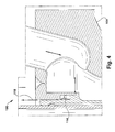
FIG. 2 shows a cross-sectional view of the known gasturbine fuel nozzle 100.FIG. 3 shows a more detailed cross sectional view of theflange 104 of the known gasturbine fuel nozzle 100 ofFIG. 2 . Air is received in amain fuel chamber 108. Fuel is introduced through a plurality of fuel holes 110 (FIG. 2 ) where it is mixed with the air and released from the gasturbine fuel nozzle 100 for ignition within the gas turbine. Within the gasturbine fuel nozzle 100 analternate fuel passage 112 may be provided. As shown inFIG. 3 , aseal 114 between thealternate fuel passage 112 and themain fuel chamber 108 prevents fuel and/or air from leaking with alternate fuel. Gasturbine fuel nozzle 100 may also include thecooling air passage 106.Seal 114 may prevent cooling air from mixing with fuel. Aseal retainer 116 holds theseal 114 in place. Theseal retainer 116 may be welded in place. Under operational conditions, theseal 114 is subjected to significant thermal and pressure forces. As a result, theseal 114 is subject to wear and may leak.FIG. 4 shows a cross sectional view of a portion of theflange 104 of the known gasturbine fuel nozzle 100. If theseal 114 leaks, air may move past theseal 114 along aleak path 118. - A first aspect of the invention provides a seal test fixture for a gas turbine fuel nozzle, comprising: an enclosed container for receiving a body of the gas turbine fuel nozzle including a seal; a test chamber coupled to the enclosed container for sealingly enclosing a flange of the gas turbine fuel nozzle and fluidly communicating with a leak path of the gas turbine fuel nozzle; an air injector opening through which pressurized air is injected into a main fuel chamber of the gas turbine fuel nozzle; and a pressure gauge for measuring an air pressure within the test chamber.
- A second aspect of the invention provides a seal testing system, comprising: a computer system including: a receiver for receiving a pre-injection pressure and a post-injection pressure; a comparator for comparing the pre-injection pressure and a post-injection pressure; and a determination system for determining an integrity of the seal based upon the comparing.
- These and other aspects, advantages and salient features of the invention will become apparent from the following detailed description, which, when taken in conjunction with the annexed drawings, where like parts are designated by like reference characters throughout the drawings, disclose embodiments of the invention.
- The above and other aspects, features and advantages of the invention will be better understood by reading the following more particular description of the invention in conjunction with the accompanying drawings.
-
FIG. 1 shows a perspective view of a known gas turbine fuel nozzle. -
FIG. 2 shows a cross-sectional view of the known gas turbine fuel nozzle. -
FIG. 3 shows cross sectional view of the flange of the known gas turbine fuel nozzle. -
FIG. 4 shows cross sectional view of a portion of the flange of the known gas turbine fuel nozzle. -
FIG. 5 shows a perspective view of a seal test fixture for a gas turbine fuel nozzle in accordance with the present invention. -
FIG. 6 shows a cross-sectional view of a portion of a seal test fixture for a gas turbine fuel nozzle in accordance with the present invention. -
FIG. 7 shows a seal test system for a gas turbine fuel nozzle in accordance with the present invention. -
FIG. 8 shows a flow diagram for a method of testing a seal in accordance with the present invention. - The drawings are not necessarily to scale. The drawings are merely schematic representations, not intended to portray specific parameters of the invention. The drawings are intended to depict only typical embodiments of the invention, and therefore should not be considered as limiting the scope of the invention. In the drawings, like numbering represents like elements.
- Referring to
FIG. 5 , a perspective view of one embodiment of aseal test fixture 500 for a gasturbine fuel nozzle 100 is shown. Referring toFIG. 6 , a cross-sectional view of one embodiment of a portion of aseal test fixture 500 for a gasturbine fuel nozzle 100 is shown. Theseal test fixture 500 may include an enclosedcontainer 502 for receiving thebody 102 of the gasturbine fuel nozzle 100 including theseal 114. Enclosedcontainer 502 may include metal, polymer, or any other material capable of sustaining pressures of up to about 100 psi. It will be readily recognized that if higher pressures are indicated for testing theseal 114, then enclosedcontainer 502 may include materials capable of withstanding the higher pressures. - The
seal test fixture 500 may further include atest chamber 504 coupled to the enclosedcontainer 502 for sealingly enclosing the flange 104 (FIG. 5 ) of the gasturbine fuel nozzle 100 and in fluid communication with theleak path 116 of the gasturbine fuel nozzle 100 through which theseal 114 would leak air and/or fuel. - The
seal test fixture 500 may further include an air injector opening 506 through which pressurized air is injected into amain fuel chamber 108 of the gasturbine fuel nozzle 100. Theseal test fixture 500 may include anair injector 508 sealingly connected to the air injector opening 506 for a supply of air that may be injected through the air injector opening 506 into themain fuel chamber 108. Theair injector 508 may be able to inject air up to a pressure of up to about 100 psi. - The
seal test fixture 500 may further include a pressure gauge 510 (FIG. 5 ) for measuring an air pressure within thetest chamber 504. Thepressure gauge 510 may receive air from thetest chamber 504 and display and/or communicate a measurement of the air pressure in thetest chamber 504. - The
test chamber 504 may include a plurality ofconnection holes 512. The plurality ofconnection holes 512 may be used to secure theflange 104 to thetest chamber 504. Eachconnection hole 512 may receive one of a plurality ofconnectors 514 for securing theflange 104 to thetest chamber 504. Each of the plurality ofconnectors 514 may include a bolt, screw, pin, or any other known device for connecting. - The
seal test fixture 500 may further include afirst gasket 516 between the enclosedcontainer 502 and thetest chamber 504.First gasket 516 may provide an improved seal between the enclosedcontainer 502 and thetest chamber 504. Thetest chamber 504 may be in part or may include afirst part 518 and asecond part 520. Thefirst part 518 may substantially cover and secure theflange 104. Thesecond part 520 may enclose thecooling air passage 106. The test chamber may 504 include asecond gasket 522 between thefirst part 518 and thesecond part 520.Test chamber 504 may include metal, polymer, or any other material capable of sustaining pressures of up to about 100 psi. It will be readily recognized that if higher pressures are indicated for testing the seal, thentest chamber 504 may include materials capable of withstanding the higher pressures. - In
FIG. 7 , one embodiment of theseal test fixture 600 with acomputer system 700 is shown.Computer system 700 including: areceiver 702 for receiving a pre-injection pressure and a post-injection pressure; acomparator 704 for comparing the pre-injection pressure and a post-injection pressure; and adetermination system 706 for determining whether the seal has a leak or is substantially intact based upon the comparing. -
Seal test fixture 600 may be used to a method for testing theseal 114 of the gasturbine fuel nozzle 100 describe herein. Referring toFIG. 8 , a flow diagram of one embodiment of a method of testing theseal 114 of the gasturbine fuel nozzle 100 is shown. At S1, thebody 102 of the gasturbine fuel nozzle 100 is contained in the enclosedcontainer 602 of theseal test fixture 600. At S2, thetest chamber 604 is coupled to theenclosed container 602 thereby sealingly enclosing theflange 104 of the gasturbine fuel nozzle 100 and in fluid communication with theleak path 116 of the gasturbine fuel nozzle 100 through which theseal 114 would leak. At S3, the air pressure in thetest chamber 604 before injecting air (see S4) is measured. At S4, air is injected through the air injection opening 606 into themain fuel chamber 108 of the gasturbine fuel nozzle 100 filling theenclosed container 602 with injected air up to a pressure up to about 100 psi. At S5, the air pressure in thetest chamber 604 after injecting is measured. At S6, the air pressure before the injecting and the air pressure after the injecting is compared. At S7, a leak through theseal 114 is determined when the air pressure after the injecting is higher than the air pressure before the injecting. At S8, theseal 114 is replaced in response to determining the potential leak. Alternatively at S9, theseal 114 is determined to be substantially intact when the air pressure after the injecting is substantially the same as the air pressure before the injecting. - Referring back to
FIG. 7 ,computer system 700 is shown in communication with auser 750.User 750 may, for example, be a programmer or operator.User 750 may also be a device or a computer. Interactions between these components andcomputer system 700 will be discussed in subsequent portions of this application.Computer system 700 is shown including a processing component (PC) 708 (e.g., one or more processors), a storage component 710 (e.g., a storage hierarchy), an input/output (I/O) component 712 (e.g., one or more I/O interfaces and/or devices), and acommunications pathway 714. In one embodiment,processing component 708 executes program code, such asseal testing system 716, which is at least partially embodied instorage component 710. While executing program code,processing component 708 can process data, which can result in reading and/or writing the data to/fromstorage component 710 and/or I/O component 712 for further processing.Pathway 714 provides a communications link between each of the components incomputer system 700. I/O component 712 can comprise one or more human I/O devices or storage devices, which enableuser 750 to interact withcomputer system 700 and/or one or more communications devices to enableuser 750 to communicate withcomputer system 700 using any type of communications link. To this extent, sealtesting system 716 can manage a set of interfaces (e.g., graphical user interface(s), application program interface, and/or the like) that enable human and/or system interaction withseal testing system 716. - In any event,
computer system 700 can comprise one or more general purpose computing articles of manufacture (e.g., computing devices) capable of executing program code installed thereon. As used herein, it is understood that "program code" means any collection of instructions, in any language, code or notation, that cause a computing device having an information processing capability to perform a particular function either directly or after any combination of the following: (a) conversion to another language, code or notation; (b) reproduction in a different material form; and/or (c) decompression. To this extent, sealtesting system 716 can be embodied as any combination of system software and/or application software. In any event, the technical effect ofcomputer system 700 is to provide processing instructions for testing the seal of the gas turbine fuel nozzle. - Further,
seal testing system 716 can be implemented using a set ofmodules 718. In this case, amodule 718 can enablecomputer system 700 to perform a set of tasks used byseal testing system 716, and can be separately developed and/or implemented apart from other portions ofseal testing system 716.Seal testing system 716 may includemodules 718 which comprise a specific use machine/hardware and/or software. Regardless, it is understood that two ormore modules 718, and/or systems may share some/all of their respective hardware and/or software. Further, it is understood that some of the functionality discussed herein may not be implemented or additional functionality may be included as part ofcomputer system 700. - When
computer system 700 comprises multiple computing devices, each computing device may have only a portion ofseal testing system 716 embodied thereon (e.g., one or more modules 718). However, it is understood thatcomputer system 700 and sealtesting system 716 are only representative of various possible equivalent computer systems that may perform a process described herein. To this extent, in other embodiments, the functionality provided bycomputer system 700 and sealtesting system 716 can be at least partially implemented by one or more computing devices that include any combination of general and/or specific purpose hardware with or without program code. In each embodiment, the hardware and program code, if included, can be created using standard engineering and programming techniques, respectively. - Regardless, when
computer system 700 includes multiple computing devices, the computing devices can communicate over any type of communications link. Further, while performing a process described herein,computer system 700 can communicate with one or more other computer systems using any type of communications link. In either case, the communications link can comprise any combination of various types of wired and/or wireless links; comprise any combination of one or more types of networks; and/or utilize any combination of various types of transmission techniques and protocols. - As discussed herein,
seal testing system 716 enablescomputer system 700 to provide processing instructions for testing the seal of the gas turbine fuel nozzle.Seal testing system 716 may include logic, which may include the following functions:receiver 702,comparator 704, anddetermination system 706. In one embodiment,seal testing system 716 may include logic to perform the above-stated functions. Structurally, the logic may take any of a variety of forms such as a field programmable gate array (FPGA), a microprocessor, a digital signal processor, an application specific integrated circuit (ASIC) or any other specific use machine structure capable of carrying out the functions described herein. Logic may take any of a variety of forms, such as software and/or hardware. However, for illustrative purposes, sealtesting system 716 and logic included therein will be described herein as a specific use machine. As will be understood from the description, while logic is illustrated as including each of the above-stated functions, not all of the functions are necessary according to the teachings of the invention as recited in the appended claims. - While shown and described herein as a
seal testing system 716, it is understood that aspects of the invention further provide various alternative embodiments. For example, in one embodiment, the invention provides a computer program embodied in at least one computer-readable medium, which when executed, enables a computer system to measure gas mixtures. To this extent, the computer-readable medium includes program code, such asseal testing system 716, which implements some or all of a process described herein. It is understood that the term "computer-readable medium" comprises one or more of any type of tangible medium of expression capable of embodying a copy of the program code (e.g., a physical embodiment). For example, the computer-readable medium can comprise: one or more portable storage articles of manufacture; one or more memory/storage components of a computing device; paper; and/or the like. - In still another embodiment, the invention provides a method of testing the seal of the gas turbine fuel nozzle. In this case, a computer system, such as computer system 700 (
FIG. 7 ), can be obtained (e.g., created, maintained, made available, etc.) and one ormore modules 718 for performing a process described herein can be obtained (e.g., created, purchased, used, modified, etc.) and deployed to thecomputer system 700. To this extent, the deployment can comprise one or more of: (1) installing program code on a computing device from a computer-readable medium; (2) adding one or more computing and/or I/O devices to thecomputer system 700; and (3) incorporating and/or modifying thecomputer system 700 to enable it to perform a process described herein. - It is understood that aspects of the invention can be implemented as part of a business method that performs a process described herein on a subscription, advertising, and/or fee basis. That is, a service provider could offer to provide processing instructions for testing the seal of the gas turbine fuel nozzle.as described herein. In this case, the service provider can manage (e.g., create, maintain, support, etc.) a
computer system 700, such as computer system 700 (FIG. 1 ), that performs a process described herein for one or more customers. In return, the service provider can receive payment from the customer(s) under a subscription and/or fee agreement, receive payment from the sale of advertising to one or more third parties, and/or the like. - The terminology used herein is for the purpose of describing particular embodiments only and is not intended to be limiting of the disclosure. As used herein, the singular forms "a", "an" and "the" are intended to include the plural forms as well, unless the context clearly indicates otherwise. It will be further understood that the terms "comprises" and/or "comprising," when used in this specification, specify the presence of stated features, integers, steps, operations, elements, and/or components, but do not preclude the presence or addition of one or more other features, integers, steps, operations, elements, components, and/or groups thereof.
- While various embodiments are described herein, it will be appreciated from the specification that various combinations of elements, variations or improvements therein may be made by those skilled in the art, and are within the scope of the invention. In addition, many modifications may be made to adapt a particular situation or material to the teachings of the invention without departing from essential scope thereof. Therefore, it is intended that the invention not be limited to the particular embodiment disclosed as the best mode contemplated for carrying out this invention, but that the invention will include all embodiments falling within the scope of the appended claims.
- Various aspects and embodiments of the present invention are defined by the following numbered clauses:
- 1. A seal test fixture for a gas turbine fuel nozzle, comprising:
- an enclosed container for receiving a body of the gas turbine fuel nozzle including a seal;
- a test chamber coupled to the enclosed container for sealingly enclosing a flange of the gas turbine fuel nozzle and fluidly communicating with a leak path of the gas turbine fuel nozzle;
- an air injector opening through which pressurized air is injected into a main fuel chamber of the gas turbine fuel nozzle; and
- a pressure gauge for measuring an air pressure within the test chamber.
- 2. The seal test fixture of
clause 1, wherein an air injector is sealingly connected to the air injector opening. - 3. The seal test fixture of any preceding clause, wherein the test chamber includes a plurality of connection holes, each connection hole for receiving one of a plurality of connectors for securing the flange to the test chamber.
- 4. The seal test fixture of any preceding clause, further comprising:
- a first gasket between the enclosed container and the test chamber.
- 5. The seal test fixture of any preceding clause, wherein the test chamber includes a first part and a second part, wherein the first part substantially covers and secures the flange and the second part encloses a cooling air passage.
- 6. The seal test fixture of any preceding clause, further comprising:
- a second gasket between the first part and the second part.
- 7. The seal test fixture of any preceding clause, wherein the container and the test chamber includes one of a metal or a polymer.
- 8. The seal test fixture of any preceding clause, further comprising:
- a computer system including:
- a receiver for receiving a pre-injection pressure and a post-injection pressure;
- a comparator for comparing the pre-injection pressure and a post-injection pressure; and
- a determination system for determining whether the seal leaks or is substantially intact based upon the comparing.
- a computer system including:
- 9. The seal test fixture of any preceding clause, wherein the seal is determined to leak when the post-injection air pressure is higher than the pre-injection air pressure.
- 10. The seal test fixture 8, wherein the seal is determined to be substantially intact when the post-injection air pressure is the same as the pre-injection air pressure.
- 11. A seal testing system, comprising:
- a computer system including:
- a receiver for receiving a pre-injection pressure and a post-injection pressure;
- a comparator for comparing the pre-injection pressure and a post-injection pressure; and
- a determination system for determining whether the seal leaks or is substantially intact based upon the comparing.
- a computer system including:
- 12. The seal testing system of any preceding clause, wherein the seal is determined to leak when the post-injection air pressure is higher than the pre-injection air pressure.
- 13. The seal testing system of any preceding clause, wherein the seal is determined to be substantially intact when the post-injection air pressure is the same as the pre-injection air pressure.
- 14. The seal testing system of any preceding clause, further comprising:
- a seal test fixture for a gas turbine fuel nozzle, comprising:
- an enclosed container for receiving a body of the gas turbine fuel nozzle including a seal;
- a test chamber coupled to the enclosed container for sealingly enclosing a flange of the gas turbine fuel nozzle and fluidly communicating with a leak path of the gas turbine fuel nozzle;
- an air injector opening through which pressurized air is injected into a main fuel chamber of the gas turbine fuel nozzle; and
- a pressure gauge for measuring an air pressure within the test chamber.
- a seal test fixture for a gas turbine fuel nozzle, comprising:
- 15. The seal testing system of any preceding clause, wherein an air injector is sealingly connected to the air injector opening.
- 16. The seal testing system of any preceding clause, wherein the test chamber includes a plurality of connection holes, each connection hole for receiving one of a plurality of connectors for securing the flange to the test chamber.
- 17. The seal testing system of any preceding clause, further comprising:
- a first gasket between the enclosed container and the test chamber.
- 18. The seal testing system of any preceding clause, wherein the test chamber includes a first part and a second part, wherein the first part substantially covers and secures the flange and the second part encloses a cooling air passage.
- 19. The seal testing system of any preceding clause, further comprising:
- a second gasket between the first part and the second part.
- 20. The seal testing system of any preceding clause, wherein the container and the test chamber include one of a metal or a polymer.
Claims (14)
- A seal test fixture (500) for a gas turbine fuel nozzle (100), comprising:an enclosed container (502) for receiving a body (102) of the gas turbine fuel nozzle (100) including a seal (140);a test chamber (504) coupled to the enclosed container (502) for sealingly enclosing a flange (104) of the gas turbine fuel nozzle (100) and fluidly communicating with a leak path of the gas turbine fuel nozzle (100);an air injector opening (506) through which pressurized air is injected into a main fuel chamber (108) of the gas turbine fuel nozzle (100); anda pressure gauge (510) for measuring an air pressure within the test chamber (504).
- The seal test fixture of claim 1, wherein an air injector (508) is sealingly connected to the air injector opening (506).
- The seal test fixture of claim 1 or claim 2, wherein the test chamber (504) includes a plurality of connection holes (512), each connection hole for receiving one of a plurality of connectors for securing the flange (104) to the test chamber (504).
- The seal test fixture of claim 1, 2 or 3, further comprising:a first gasket (516) between the enclosed container (502) and the test chamber (504).
- The seal test fixture of any preceding claim, wherein the test chamber (504) includes a first part (518) and a second part (520), wherein the first part (518) substantially covers and secures the flange (104) and the second part (520) encloses a cooling air passage (106).
- The seal test fixture of claim 5, further comprising:a second gasket (522) between the first part (518) and the second part (520).
- The seal test fixture of any preceding claim, wherein the container and the test chamber (504) includes one of a metal or a polymer.
- The seal test fixture of any preceding claim, further comprising:a computer system (700) including:a receiver (702) for receiving a pre-injection pressure and a post-injection pressure;a comparator (704) for comparing the pre-injection pressure and a post-injection pressure; anda determination system (706) for determining whether the seal leaks or is substantially intact based upon the comparing.
- The seal test fixture of claim 8, wherein the seal (114) is determined to leak when the post-injection air pressure is higher than the pre-injection air pressure.
- The seal test fixture of claim 8 or claim 9, wherein the seal (114) is determined to be substantially intact when the post-injection air pressure is the same as the pre-injection air pressure.
- A seal testing system, comprising:a computer system (700) including:a receiver (702) for receiving a pre-injection pressure and a post-injection pressure;a comparator (704) for comparing the pre-injection pressure and a post-injection pressure; anda determination system (706) for determining whether the seal leaks or is substantially intact based upon the comparing.
- The seal testing system of claim 11, wherein the seal (114) is determined to leak when the post-injection air pressure is higher than the pre-injection air pressure.
- The seal testing system of claim 11 or claim 12, wherein the seal (114) is determined to be substantially intact when the post-injection air pressure is the same as the pre-injection air pressure.
- The seal testing system of claim 11, 12 or 13, further comprising:a seal test fixture (500) for a gas turbine fuel nozzle (100) according to any one of claims 1 to 7.
Applications Claiming Priority (1)
| Application Number | Priority Date | Filing Date | Title |
|---|---|---|---|
| US13/790,348 US20140250981A1 (en) | 2013-03-08 | 2013-03-08 | Seal test fixture for a gas turbine fuel nozzle |
Publications (1)
| Publication Number | Publication Date |
|---|---|
| EP2803967A1 true EP2803967A1 (en) | 2014-11-19 |
Family
ID=50238146
Family Applications (1)
| Application Number | Title | Priority Date | Filing Date |
|---|---|---|---|
| EP14157163.8A Withdrawn EP2803967A1 (en) | 2013-03-08 | 2014-02-28 | Seal test fixture for a gas turbine fuel nozzle |
Country Status (2)
| Country | Link |
|---|---|
| US (1) | US20140250981A1 (en) |
| EP (1) | EP2803967A1 (en) |
Families Citing this family (7)
| Publication number | Priority date | Publication date | Assignee | Title |
|---|---|---|---|---|
| US9500367B2 (en) * | 2013-11-11 | 2016-11-22 | General Electric Company | Combustion casing manifold for high pressure air delivery to a fuel nozzle pilot system |
| US10732218B2 (en) * | 2015-08-26 | 2020-08-04 | Texas Instruments Incorporated | Seal monitor for probe or test chamber |
| CN105352664B (en) * | 2015-10-19 | 2018-09-14 | 沈阳拓荆科技有限公司 | A kind of multichannel spray equipment leak detection tool equipment and detection method |
| US10302523B2 (en) | 2016-05-27 | 2019-05-28 | Pratt & Whitney Canada Corp. | Method for testing a seal of a sealed bearing cavity |
| US10634344B2 (en) * | 2016-12-20 | 2020-04-28 | General Electric Company | Fuel nozzle assembly with fuel purge |
| US11230976B2 (en) | 2017-07-14 | 2022-01-25 | General Electric Company | Integrated fuel nozzle connection |
| FR3070417B1 (en) * | 2017-08-24 | 2019-08-23 | Safran Aircraft Engines | DEVICE FOR TESTING THE INTER-SECTOR PERMEABILITY OF TWO RING SECTIONS OF A TURBOMACHINE ELEMENT |
Citations (3)
| Publication number | Priority date | Publication date | Assignee | Title |
|---|---|---|---|---|
| US4905501A (en) * | 1987-12-24 | 1990-03-06 | Kabushiki Kaisha Nippon Automation | Jig for leak check |
| US5546789A (en) * | 1992-08-03 | 1996-08-20 | Intertech Development Company | Leakage detection system |
| US20120180494A1 (en) * | 2011-01-14 | 2012-07-19 | General Electric Company | Turbine fuel nozzle assembly |
Family Cites Families (2)
| Publication number | Priority date | Publication date | Assignee | Title |
|---|---|---|---|---|
| US4587619A (en) * | 1981-12-14 | 1986-05-06 | Scans Associates, Inc. | Method and apparatus for electronic leak testing |
| JP4103278B2 (en) * | 1999-12-07 | 2008-06-18 | 株式会社デンソー | Leak inspection device |
-
2013
- 2013-03-08 US US13/790,348 patent/US20140250981A1/en not_active Abandoned
-
2014
- 2014-02-28 EP EP14157163.8A patent/EP2803967A1/en not_active Withdrawn
Patent Citations (3)
| Publication number | Priority date | Publication date | Assignee | Title |
|---|---|---|---|---|
| US4905501A (en) * | 1987-12-24 | 1990-03-06 | Kabushiki Kaisha Nippon Automation | Jig for leak check |
| US5546789A (en) * | 1992-08-03 | 1996-08-20 | Intertech Development Company | Leakage detection system |
| US20120180494A1 (en) * | 2011-01-14 | 2012-07-19 | General Electric Company | Turbine fuel nozzle assembly |
Also Published As
| Publication number | Publication date |
|---|---|
| US20140250981A1 (en) | 2014-09-11 |
Similar Documents
| Publication | Publication Date | Title |
|---|---|---|
| EP2803967A1 (en) | Seal test fixture for a gas turbine fuel nozzle | |
| US9239008B2 (en) | Turbine leak detection system | |
| CN109063477B (en) | Automatic intelligent contract code defect detection system and method | |
| Lochau et al. | Incremental model-based testing of delta-oriented software product lines | |
| Hecht et al. | Detecting antipatterns in android apps | |
| Stafford et al. | Architecture-level dependence analysis for software systems | |
| US9569177B2 (en) | Service extraction and application composition | |
| CN106681912A (en) | Method and device for automatic testing of code coverage rate, applied to Android system | |
| CN112685023A (en) | Front-end development processing method, device, equipment and storage medium based on basic library | |
| Teixeira et al. | Multi-language static code analysis on the lara framework | |
| Jansen et al. | Scriptless gui testing on mobile applications | |
| Xie et al. | Automatic extraction of abstract-object-state machines from unit-test executions | |
| Buffoni et al. | Traceability and impact analysis in requirement verification | |
| Visser et al. | Test input generation for red-black trees using abstraction | |
| Merilinna et al. | Verification and validation in the context of domain-specific modelling | |
| Scarsbrook et al. | MetropolJS: Visualizing and debugging large-scale JavaScript program structure with treemaps | |
| CN114780952B (en) | Sensitive application call scenario detection method, system and storage medium | |
| Suganya et al. | A study of object oriented testing techniques: Survey and challenges | |
| Lewis | Architectural design for secure smart contract development | |
| CN106909500A (en) | The detection method and system of mistake are introduced in Airborne Software development process | |
| Bijlsma et al. | Template Method test pattern | |
| Coq et al. | The sqale quality and analysis models for assessing the quality of ada source code | |
| Diwaker et al. | Metrics used in component based software Engineering | |
| Rajendran | Karna for a trustable hardware | |
| Rocheteau | Energy wasting rate as a metrics for green computing and static analysis |
Legal Events
| Date | Code | Title | Description |
|---|---|---|---|
| PUAI | Public reference made under article 153(3) epc to a published international application that has entered the european phase |
Free format text: ORIGINAL CODE: 0009012 |
|
| 17P | Request for examination filed |
Effective date: 20140228 |
|
| AK | Designated contracting states |
Kind code of ref document: A1 Designated state(s): AL AT BE BG CH CY CZ DE DK EE ES FI FR GB GR HR HU IE IS IT LI LT LU LV MC MK MT NL NO PL PT RO RS SE SI SK SM TR |
|
| AX | Request for extension of the european patent |
Extension state: BA ME |
|
| R17P | Request for examination filed (corrected) |
Effective date: 20150519 |
|
| RBV | Designated contracting states (corrected) |
Designated state(s): AL AT BE BG CH CY CZ DE DK EE ES FI FR GB GR HR HU IE IS IT LI LT LU LV MC MK MT NL NO PL PT RO RS SE SI SK SM TR |
|
| STAA | Information on the status of an ep patent application or granted ep patent |
Free format text: STATUS: THE APPLICATION IS DEEMED TO BE WITHDRAWN |
|
| 18D | Application deemed to be withdrawn |
Effective date: 20160901 |