EP2803966B1 - Method for detecting detonation phenomena in an internal combustion engine - Google Patents
Method for detecting detonation phenomena in an internal combustion engine Download PDFInfo
- Publication number
- EP2803966B1 EP2803966B1 EP14168371.4A EP14168371A EP2803966B1 EP 2803966 B1 EP2803966 B1 EP 2803966B1 EP 14168371 A EP14168371 A EP 14168371A EP 2803966 B1 EP2803966 B1 EP 2803966B1
- Authority
- EP
- European Patent Office
- Prior art keywords
- given
- cylinder
- account
- maps
- engine point
- Prior art date
- Legal status (The legal status is an assumption and is not a legal conclusion. Google has not performed a legal analysis and makes no representation as to the accuracy of the status listed.)
- Active
Links
- 238000002485 combustion reaction Methods 0.000 title claims description 186
- 238000005474 detonation Methods 0.000 title claims description 77
- 238000000034 method Methods 0.000 title claims description 38
- 230000006870 function Effects 0.000 claims description 18
- 230000003247 decreasing effect Effects 0.000 claims description 8
- 230000010355 oscillation Effects 0.000 claims description 2
- 230000000593 degrading effect Effects 0.000 claims 1
- 238000001914 filtration Methods 0.000 claims 1
- 239000000446 fuel Substances 0.000 description 6
- 239000007789 gas Substances 0.000 description 5
- 239000000126 substance Substances 0.000 description 4
- 230000009471 action Effects 0.000 description 3
- 230000000694 effects Effects 0.000 description 3
- 125000004122 cyclic group Chemical group 0.000 description 2
- 230000007423 decrease Effects 0.000 description 2
- 239000000203 mixture Substances 0.000 description 2
- TVMXDCGIABBOFY-UHFFFAOYSA-N octane Chemical compound CCCCCCCC TVMXDCGIABBOFY-UHFFFAOYSA-N 0.000 description 2
- 230000008569 process Effects 0.000 description 2
- 238000005070 sampling Methods 0.000 description 2
- 206010011878 Deafness Diseases 0.000 description 1
- 230000006835 compression Effects 0.000 description 1
- 238000007906 compression Methods 0.000 description 1
- 238000010276 construction Methods 0.000 description 1
- 239000002360 explosive Substances 0.000 description 1
- 239000002184 metal Substances 0.000 description 1
- 238000012986 modification Methods 0.000 description 1
- 230000004048 modification Effects 0.000 description 1
- 238000011144 upstream manufacturing Methods 0.000 description 1
Images

Classifications
-
- F—MECHANICAL ENGINEERING; LIGHTING; HEATING; WEAPONS; BLASTING
- F02—COMBUSTION ENGINES; HOT-GAS OR COMBUSTION-PRODUCT ENGINE PLANTS
- F02D—CONTROLLING COMBUSTION ENGINES
- F02D35/00—Controlling engines, dependent on conditions exterior or interior to engines, not otherwise provided for
- F02D35/02—Controlling engines, dependent on conditions exterior or interior to engines, not otherwise provided for on interior conditions
- F02D35/027—Controlling engines, dependent on conditions exterior or interior to engines, not otherwise provided for on interior conditions using knock sensors
-
- F—MECHANICAL ENGINEERING; LIGHTING; HEATING; WEAPONS; BLASTING
- F02—COMBUSTION ENGINES; HOT-GAS OR COMBUSTION-PRODUCT ENGINE PLANTS
- F02D—CONTROLLING COMBUSTION ENGINES
- F02D41/00—Electrical control of supply of combustible mixture or its constituents
- F02D41/008—Controlling each cylinder individually
-
- F—MECHANICAL ENGINEERING; LIGHTING; HEATING; WEAPONS; BLASTING
- F02—COMBUSTION ENGINES; HOT-GAS OR COMBUSTION-PRODUCT ENGINE PLANTS
- F02P—IGNITION, OTHER THAN COMPRESSION IGNITION, FOR INTERNAL-COMBUSTION ENGINES; TESTING OF IGNITION TIMING IN COMPRESSION-IGNITION ENGINES
- F02P17/00—Testing of ignition installations, e.g. in combination with adjusting; Testing of ignition timing in compression-ignition engines
- F02P17/12—Testing characteristics of the spark, ignition voltage or current
-
- F—MECHANICAL ENGINEERING; LIGHTING; HEATING; WEAPONS; BLASTING
- F02—COMBUSTION ENGINES; HOT-GAS OR COMBUSTION-PRODUCT ENGINE PLANTS
- F02P—IGNITION, OTHER THAN COMPRESSION IGNITION, FOR INTERNAL-COMBUSTION ENGINES; TESTING OF IGNITION TIMING IN COMPRESSION-IGNITION ENGINES
- F02P5/00—Advancing or retarding ignition; Control therefor
- F02P5/04—Advancing or retarding ignition; Control therefor automatically, as a function of the working conditions of the engine or vehicle or of the atmospheric conditions
- F02P5/145—Advancing or retarding ignition; Control therefor automatically, as a function of the working conditions of the engine or vehicle or of the atmospheric conditions using electrical means
- F02P5/15—Digital data processing
- F02P5/152—Digital data processing dependent on pinking
- F02P5/1522—Digital data processing dependent on pinking with particular means concerning an individual cylinder
-
- G—PHYSICS
- G01—MEASURING; TESTING
- G01L—MEASURING FORCE, STRESS, TORQUE, WORK, MECHANICAL POWER, MECHANICAL EFFICIENCY, OR FLUID PRESSURE
- G01L23/00—Devices or apparatus for measuring or indicating or recording rapid changes, such as oscillations, in the pressure of steam, gas, or liquid; Indicators for determining work or energy of steam, internal-combustion, or other fluid-pressure engines from the condition of the working fluid
- G01L23/22—Devices or apparatus for measuring or indicating or recording rapid changes, such as oscillations, in the pressure of steam, gas, or liquid; Indicators for determining work or energy of steam, internal-combustion, or other fluid-pressure engines from the condition of the working fluid for detecting or indicating knocks in internal-combustion engines; Units comprising pressure-sensitive members combined with ignitors for firing internal-combustion engines
- G01L23/221—Devices or apparatus for measuring or indicating or recording rapid changes, such as oscillations, in the pressure of steam, gas, or liquid; Indicators for determining work or energy of steam, internal-combustion, or other fluid-pressure engines from the condition of the working fluid for detecting or indicating knocks in internal-combustion engines; Units comprising pressure-sensitive members combined with ignitors for firing internal-combustion engines for detecting or indicating knocks in internal combustion engines
- G01L23/225—Devices or apparatus for measuring or indicating or recording rapid changes, such as oscillations, in the pressure of steam, gas, or liquid; Indicators for determining work or energy of steam, internal-combustion, or other fluid-pressure engines from the condition of the working fluid for detecting or indicating knocks in internal-combustion engines; Units comprising pressure-sensitive members combined with ignitors for firing internal-combustion engines for detecting or indicating knocks in internal combustion engines circuit arrangements therefor
- G01L23/226—Devices or apparatus for measuring or indicating or recording rapid changes, such as oscillations, in the pressure of steam, gas, or liquid; Indicators for determining work or energy of steam, internal-combustion, or other fluid-pressure engines from the condition of the working fluid for detecting or indicating knocks in internal-combustion engines; Units comprising pressure-sensitive members combined with ignitors for firing internal-combustion engines for detecting or indicating knocks in internal combustion engines circuit arrangements therefor using specific filtering
-
- G—PHYSICS
- G01—MEASURING; TESTING
- G01L—MEASURING FORCE, STRESS, TORQUE, WORK, MECHANICAL POWER, MECHANICAL EFFICIENCY, OR FLUID PRESSURE
- G01L23/00—Devices or apparatus for measuring or indicating or recording rapid changes, such as oscillations, in the pressure of steam, gas, or liquid; Indicators for determining work or energy of steam, internal-combustion, or other fluid-pressure engines from the condition of the working fluid
- G01L23/22—Devices or apparatus for measuring or indicating or recording rapid changes, such as oscillations, in the pressure of steam, gas, or liquid; Indicators for determining work or energy of steam, internal-combustion, or other fluid-pressure engines from the condition of the working fluid for detecting or indicating knocks in internal-combustion engines; Units comprising pressure-sensitive members combined with ignitors for firing internal-combustion engines
- G01L23/221—Devices or apparatus for measuring or indicating or recording rapid changes, such as oscillations, in the pressure of steam, gas, or liquid; Indicators for determining work or energy of steam, internal-combustion, or other fluid-pressure engines from the condition of the working fluid for detecting or indicating knocks in internal-combustion engines; Units comprising pressure-sensitive members combined with ignitors for firing internal-combustion engines for detecting or indicating knocks in internal combustion engines
- G01L23/225—Devices or apparatus for measuring or indicating or recording rapid changes, such as oscillations, in the pressure of steam, gas, or liquid; Indicators for determining work or energy of steam, internal-combustion, or other fluid-pressure engines from the condition of the working fluid for detecting or indicating knocks in internal-combustion engines; Units comprising pressure-sensitive members combined with ignitors for firing internal-combustion engines for detecting or indicating knocks in internal combustion engines circuit arrangements therefor
- G01L23/227—Devices or apparatus for measuring or indicating or recording rapid changes, such as oscillations, in the pressure of steam, gas, or liquid; Indicators for determining work or energy of steam, internal-combustion, or other fluid-pressure engines from the condition of the working fluid for detecting or indicating knocks in internal-combustion engines; Units comprising pressure-sensitive members combined with ignitors for firing internal-combustion engines for detecting or indicating knocks in internal combustion engines circuit arrangements therefor using numerical analyses
-
- G—PHYSICS
- G01—MEASURING; TESTING
- G01M—TESTING STATIC OR DYNAMIC BALANCE OF MACHINES OR STRUCTURES; TESTING OF STRUCTURES OR APPARATUS, NOT OTHERWISE PROVIDED FOR
- G01M15/00—Testing of engines
- G01M15/04—Testing internal-combustion engines
- G01M15/042—Testing internal-combustion engines by monitoring a single specific parameter not covered by groups G01M15/06 - G01M15/12
-
- G—PHYSICS
- G01—MEASURING; TESTING
- G01M—TESTING STATIC OR DYNAMIC BALANCE OF MACHINES OR STRUCTURES; TESTING OF STRUCTURES OR APPARATUS, NOT OTHERWISE PROVIDED FOR
- G01M15/00—Testing of engines
- G01M15/04—Testing internal-combustion engines
- G01M15/11—Testing internal-combustion engines by detecting misfire
-
- Y—GENERAL TAGGING OF NEW TECHNOLOGICAL DEVELOPMENTS; GENERAL TAGGING OF CROSS-SECTIONAL TECHNOLOGIES SPANNING OVER SEVERAL SECTIONS OF THE IPC; TECHNICAL SUBJECTS COVERED BY FORMER USPC CROSS-REFERENCE ART COLLECTIONS [XRACs] AND DIGESTS
- Y02—TECHNOLOGIES OR APPLICATIONS FOR MITIGATION OR ADAPTATION AGAINST CLIMATE CHANGE
- Y02T—CLIMATE CHANGE MITIGATION TECHNOLOGIES RELATED TO TRANSPORTATION
- Y02T10/00—Road transport of goods or passengers
- Y02T10/10—Internal combustion engine [ICE] based vehicles
- Y02T10/40—Engine management systems
Definitions
- the present invention relates to method for detecting detonation phenomena in an internal combustion engine.
- a spark ignited, internal combustion engine comprises a number of cylinders, each of which is provided with a piston, which cyclically slides within the cylinder, and with a spark plug, which is cyclically operated by an electronic control unit to generate a spark between its electrodes, and thus determine the ignition of the compressed gases within the cylinder itself.
- the control unit comprises a memory, in which there is stored a series of maps which provide the operating values of the spark plugs as a function of the current engine point; in particular, the maps provide the value of the spark advance, i.e. the value of the angular interval existing between the ignition, i.e.
- the values of the spark advance stored in the maps contained in the control unit are determined during the engine set up phase to attempt to ensure a good combustion under all possible conditions of operation, obtain a good thermal efficiency of the engine while safeguarding the integrity of the engine itself, i.e. avoiding the presence of excessive detonation phenomena in the cylinders.
- Detonation is an explosive type combustion of part of the air-fuel mixture, which occurs before the mixture is reached by the flame front generated by the spark plug; a series of pressure waves, which cross the combustion chamber and violently impact against the metal walls, are created upon the detonation.
- Detonation occurs when given critical temperature and pressure values are exceeded inside the chamber (which may vary even considerably from engine to engine) and which, when occurring at medium-to-low rpm, often cause a typical, clearly perceivable metallic noise known as "knocking” or "pinging".
- Detonation normally occurs when spark advance is excessive, when a fuel with an excessively low octane rating is used (the antiknock potential of a fuel is indeed indicated by its octane rating) or, for supercharged engines, when the supercharging pressure is too high.
- the combustion trend is influenced by many factors (the most important are the fuel features, the engine head temperature, the spark plug decay), the effect of which is substantially impossible to predict with accuracy. For this reason, the absence of excessive detonation must be detected and, in the case of excessive detonation in a cylinder, the control unit must reduce the value of the spark advance for such a cylinder so as to eliminate the detonation in the cylinder itself (so the maximum pressure reached in the cylinder is reduced and reached later with respect to TDC, making the detonation event "less likely”).
- control unit and a method for detecting detonation phenomena in an internal combustion engine are provided as claimed in the appended claims.
- reference numeral 1 indicates as a whole a spark ignited internal combustion engine comprising four cylinders 2 in a straight arrangement.
- Each cylinder 2 comprises a respective piston 3 which is mechanically connected by means of a connecting rod to a drive shaft 4 to transmit the force generated by the combustion in cylinder 2 to the drive shaft 4 itself.
- the internal combustion engine 1 comprises an intake manifold 5, which is connected to each cylinder 2 by means of two intake valves 6 (of which only one is shown in figure 2 ) and receives fresh air (i.e. air from the outside environment) though a butterfly valve 7 which is moveable between a closing position and a maximum opening position. Furthermore, the internal combustion engine 1 comprises an exhaust manifold 8, which is connected to each cylinder 2 by means of two exhaust valves 9 (only one of which is shown in figure 2 ) which flows into an emission pipe (not shown) to emit the gases produced in the combustion into the atmosphere.
- each exhaust valve 9 is directly controlled by a camshaft 10 which receives motion from the drive shaft 4; instead, the position of the intake valves 6 is controlled by a valve opening controlling device 11 which controls the intake valves 6 by managing the opening angle and lift so as to control the delivered torque by means of the intake valves 6.
- the valve opening control device 11 uses a traditional camshaft 12 which receives motion from the drive shaft 4 and for each intake valve 6 comprises an electrically controlled hydraulic actuator 13 (i.e. controlled by means of a solenoid valve), which is interposed between a stem of the intake valve 6 and the camshaft 12.
- each hydraulic actuator 13 By appropriately controlling each hydraulic actuator 13, it is possible to adjust the motion transmitted by the camshaft 12 to the intake valve stem 6, and it is thus possible to adjust the actual lift of the intake valve 6.
- the action of the control device 11 allows to vary the actual lift of each intake valve 6 independently from the other intake valves 6, for each cylinder 2 and engine cycle.
- a corresponding injector 14 is provided for each cylinder 2; according to the embodiment shown in figure 2 , the injector is of the indirect type and thus each injector 14 is arranged upstream of a cylinder 2 in an intake pipe which connects the intake manifold 5 to cylinder 2. According to an alternative embodiment (not shown), the injector is of the direct type and thus each injector 14 is partially arranged within cylinder 2.
- each cylinder 2 comprises a spark plug 15, which is arranged through the top of cylinder 2 in central position between the intake valves 5 and the exhaust valves 9 and is cyclically activated to determine the ignition of the compressed gases within cylinder 2 at the end of each compression stroke.
- Engine 1 comprises a control unit 16, which governs the operation of the internal combustion engine 1 and also controls the spark plugs 15 to determine the ignition of the compressed gases in each cylinder 2.
- the control unit 16 comprises a memory 17 in which a series of maps which provide the operating values of the spark plugs 15 as a function of the current engine point are stored; in particular, the maps stored in the memory 17 provide a standard spark advance for each spark plug 15 (i.e. for each cylinder 2).
- control unit 16 The method for controlling the detonation in the internal combustion engine 1 which is implemented by the control unit 16 is described below.
- the method for detonation control method which is implemented by the control unit 16 includes providing an indication of the intensity of the detonation phenomenon in the internal combustion engine 1 by appropriating processing a signal coming from one or more detonation sensors connected to the control unit 16. For example, a detonation sensor arranged to determine the ignition of the compressed gases within each cylinder 2 is provided for each spark plug 15.
- each detonation sensor comprises a voltage gauge which is connected and arranged in series to the electric circuit of the spark plug 15 to measure the voltage at the terminals of the electrodes of the spark plug 15 during combustion.
- each detonation sensor comprises a pressure gauge which measures the maximum amplitude pressure oscillation (MAPO) of the intensity of the pressure waves generated in the cylinders 2 of the internal combustion engine 1 during combustion.
- MAPO maximum amplitude pressure oscillation
- detonation sensors comprise an accelerometer, which is preferably connected to a motor housing of the internal combustion engine 1.
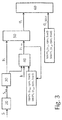
- Figure 3 diagrammatically shows the detonation control method which is implemented by the control unit 16, in which block 20 receives in input the signal or signals coming from said one or more detonation sensors connected to the control unit 16 and each comprising a respective voltage gauge; block 20 processes the signal or signals coming from said one or more detonation sensors connected to the control unit 16 and then outputs the processed signal to the following block 30.
- the signal or signals coming from said one or more detonation sensors connected to the control unit 16 is or are sampled at a constant frequency determined during a preliminary adjustment and set up phase.
- a sampling frequency is equal to 50 kHz.
- the sampling frequency assumes the same value for all the detonation sensors.
- the derivative is calculated from the rectified signal and thus transmitted block 30.
- the derivative action of the rectified signal has the drawback of making the detonation control method which is implemented by the control unit 16 excessively sensitive to variations of the signal itself.
- the integral is calculated from the rectified signal and thus transmitted to block 30.
- the integral action on the rectified signal allows the detonation control method implemented by the control unit 16 to store the passed values of the signal. As shown in figure 3 , the integrated signal is then transmitted to block 30.
- the integrated signal which is transmitted to block 30 simply represents the combustion energy.
- a combustion energy clearly depends on cylinder 2 and on the engine point in which the combustion is being observed because the signal comes from a detonation sensor, which is connected to the electric circuit of a respective spark plug 15 to measure the voltage at the terminals of the electrodes of the spark plug 15 itself during combustion in a given engine point of the respective cylinder 2.
- the detonation energy of each combustion taken into account (i.e. for the cylinder 2 taken into account in a given engine point) is variable between a zero value, which indicates complete absence of detonation, and a maximum value, which indicates a completely detonating combustion.
- the detonation energy of each combustion taken into account (i.e. for the cylinder 2 taken into account in a given engine point) assumes a log-normal distribution ⁇ 2 .
- Such a log-normal distribution ⁇ 2 may be distorted by means of a mathematical device (i.e. by applying a logarithmic curve) and is transformed into a Gaussian or normal distribution, characterized by a mean value ⁇ 1 and a standard deviation ⁇ 1 .
- the log-normal distribution ⁇ 2 is simply the probability distribution of an aleatory variable the logarithm of which follows a normal distribution characterized by a mean value ⁇ 1 and by a standard deviation ⁇ 1 .
- Block 30 is thus prepared to receive in input the log-normal distribution ⁇ 2 of the detonation energy for each combustion taken into account (i.e. for the cylinder 2 taken into account in a given engine point) and process it so as to output the normal distribution of the detonation energy for each combustion taken into account (i.e. for the cylinder 2 taken into account in a given engine point).
- the processing of block 30 of the log-normal distribution ⁇ 2 of the detonation energy in each combustion taken into account is calculated because the mean value ⁇ 1 and the standard deviation ⁇ 1 are independent in the normal distribution although they both depend on the engine point.
- the normal distribution of the detonation energy of each combustion taken into account is characterized by a mean value ⁇ i and by a standard deviation ⁇ i .
- the mean value ⁇ i is the nominal noise contribution of the combustion taken into account (i.e. for the cylinder 2 taken into account in the current engine point).
- the mean value ⁇ i is the energy, i.e. the mean noise, of the combustion taken into account (i.e. for the cylinder 2 in the current engine point).
- Standard deviation ⁇ i is determined instead by the cyclic variability, including incorrect combustion phenomena (misfire, detonation etc.).
- the deviation of the value of the i-th combustion from the mean value allows to identify the trend or predisposition to detonate of the combustion taken into account (i.e. for the cylinder 2 in the current engine point).
- Block 30 thus provides a representative value of the overall noise (mean nominal noise +/- noise due to specific combustion cycle phenomena which occurred for the cylinder 2 taken into account and in the current engine point, which are impossible to separate beforehand from the mean nominal noise).
- block 30 provides the overall combustion energy ⁇ i of the i-th combustion taken into account for the cylinder 2 taken into account in the current engine point.
- the combustion energy ⁇ i of the i-th combustion taken into account for the cylinder 2 taken into account in the current engine point block 30 output from block 40 is transmitted and inputted into a block 40 which is suited to determine the average combustion energy ⁇ i _ m for the cylinder 2 taken into account in the current engine point.
- Block 40 is simply a filter, preferably of the lowpass type. According to a preferred variant, such filter is a first order filter. Also in this case, it is apparent that a correct determination of the constant k filter in block 40 is a fundamental aspect of the method for controlling the detonation in the internal combustion engine 1 which is implemented by the control unit 16.
- the constant k filter must indeed result from the trade-off between the need of independence of the single i-th combustion taken into account for the cylinder 2 taken into account in the current engine point and the capacity of the filter itself to react to changes of conditions, i.e. the capacity of the filter itself to adapt to variations of the cylinder 2 taken into account and current engine point (in yet other words, the filter must not be excessively "deaf" to variations of the cylinder 2 taken into account and current engine point).
- a group of maps MAPS 1 are stored in the control unit 16.
- the group of maps MAPS 1 comprises a map MAPS 1 for each cylinder 2 of the internal combustion engine 1.
- each map MAPS 1 for each cylinder 2 of the internal combustion engine 1 comprises a variable number of cells as a function of the engine points which may be explored during the running of the internal combustion engine 1.
- Each map MAPS 1 for each cylinder 2 of the internal combustion engine 1 comprises a number of cells univocally identified by the number of revolutions per minute (rpm) and the load.
- the filtered value of the combustion energy ⁇ i of the i-th combustion taken into account for the cylinder 2 taken into account in the current engine point output from block 40 is used to update the corresponding cell in the group of maps MAPS 1 ; i.e. the filtered value is used to update the map MAPS 1 of the cylinder 2 taken into account in its i-th combustion in the current engine point defined by the number of revolutions per minute (rpm) and the load (load).
- the updating of the cell in the group of maps MAPS 1 is obtained by means of a weighted mean between the value already stored in said cell in the group of maps MAPS 1 and the filtered value of the combustion energy ⁇ i in the i-th combustion taken into account for the cylinder 2 taken into account in the current engine point output from block 40.
- the mean combustion energy ⁇ i_m for the cylinder 2 taken into account in the current engine point is thus obtained by means of the weighted mean of the value already stored in the cell in the group of maps MAPS 1 and the filtered value of the combustion energy ⁇ i in the i-th combustion taken into account and is made so that by updating the cell in the group of maps ⁇ i the filtered value of the combustion energy of the i-th combustion taken into account assumes a gradually decreasing value.
- the more i-th combustions in the cylinder 2 taken into account in the current engine point from which the combustion energy ⁇ i (i.e. its nominal noise) was derived the more relevant will be the contribution of the filtered value of the combustion energy ⁇ i of the n-th combustion taken into account and the higher will be the contribution of the value already stored in the cell in the group of maps MAPS 1 .
- a group of maps MAPS 2 are also stored in the control unit 16.
- the structure of the group of maps MAPS 2 is identical to the structure of the group of maps MAPS 1 .
- the group of maps MAPS 2 comprises a map MAPS 2 for each cylinder 2 of the internal combustion engine 1; i.e. a respective map MAPS 1 of the group of maps MAPS 1 is associated to each map MAPS 2 .
- each map MAPS 2 for each cylinder 2 of the internal combustion engine 1 comprises a variable number of cells as a function of the engine points which may be explored during the running of the internal combustion engine 1.
- Each map MAPS 2 for each cylinder 2 of the internal combustion engine 1 comprises a number of cells univocally identified by the number of revolutions per minute (rpm) and the load (load). Also in this case, each cell which identifies an engine point in the maps MAPS 2 thus corresponds to a respective cell which identifies the same engine point in the MAPS 1 .
- the group of maps MAPS 2 comprises counters of the number of combustions taken into account during the life of the internal combustion engine 1 for the corresponding cylinder 2 and in a given engine point in the cells.
- the counters in the cells of the group of maps MAPS 2 are initialized in a preliminary adjustment and set up phase of the control unit 16. According to a preferred embodiment, the initialization values of the counters in the cells of the group of maps MAPS 2 are variable as a function of the cylinder 2 and/or engine point taken into account.
- a lower saturation value is also determined during a preliminary adjustment and set up phase.
- the lower saturation value is variable as a function of the cylinder 2 and/or engine point taken into account.
- the corresponding counter of the cell of the group of maps MAPS 2 which corresponds to that given cylinder 2 and that given engine point is decreased by one unit.
- the weight of the value already stored in the cell in the group of maps MAPS 1 increases and therefore the weight of the filtered value of the combustion energy ⁇ i of the i-th combustion taken into account is reduced.
- the values of the weights are thus variable during the life of the internal combustion engine 1, in particular as a function of the counter in the cell of the group of maps MAPS 2 which corresponds to that given cylinder 2 and that given engine point.
- the condition may be reached in which the counter is zero and so the filtered value of the combustion energy ⁇ i of the i-th combustion taken into account is no longer taken into consideration; in other words, the mean combustion energy ⁇ i of the i-th combustion taken into account for the cylinder 2 taken into account in the current engine point is equal to the value already stored in the cell in the group of maps MAPS 1 .
- the corresponding counter in the cell of the group of maps MAPS 2 which corresponds to that given cylinder 2 and to that given engine point is decreased by one unit until the corresponding lower saturation value is reached when a combustion is observed during the life of the internal combustion engine 1 for a given cylinder 2 and in a given engine point.
- the counter has reached the corresponding lower saturation value it is no longer decreased but maintained constant at the lower saturation value.
- the mean combustion ⁇ i of the i-th combustion taken into account for the cylinder 2 taken into account in the current engine point will continue to be equal to the weighted mean between the value already stored in the cell in the group of maps MAPS 1 and the filtered value of the combustion energy ⁇ i of the i-th combustion taken into account; wherein the value already stored in the cell in the group of maps MAPS 1 will have a predominant weight and the filtered value of the combustion energy ⁇ i of the i-th combustion taken into account will have a reduced weight.
- Block 40 thus outputs the mean combustion energy ⁇ i_m for the cylinder 2 taken into account in the current engine point which is transmitted and inputted to a block 50.
- Block 50 thus receives in input both the mean combustion energy ⁇ i_m for the cylinder 2 taken into account in the current engine point block 40 and the combustion energy ⁇ i of the i-th combustion taken into account for the cylinder 2 taken into account in the current engine point by block 30.
- Block 50 is further suited to compare the mean combustion energy value ⁇ i_m for the cylinder 2 taken into account in the current engine point with the combustion energy ⁇ i of the i-th combustion taken into account for the cylinder 2 taken into account in the current engine point.
- block 50 can establish by how much the combustion energy ⁇ i of the i-th combustion taken into account for the cylinder 2 taken into account in the current engine point differs from the mean combustion energy ⁇ i_m for the cylinder 2 taken into account in the current engine point. Block 50 thus determines the deviation of the i-th combustion taken into account for the cylinder 2 taken into account in the current engine point, which represents the cyclic variability, i.e. the tendency or predisposition to detonate of the i-th combustion taken into account for the cylinder 2 taken into account in the current engine point.
- Block 50 thus outputs the deviation of the i-th combustion taken into account for the cylinder 2 taken into account in the current engine point which is transmitted and inputted into a block 60.
- Block 60 receives in input both the deviation of the i-th combustion taken into account for the cylinder 2 taken into account in the current engine point from block 50 and the maximum tolerable deviation for the cylinder 2 taken into account in the current engine point.
- block 60 is suited to compare the deviation of the i-th combustion taken into account for the cylinder 2 taken into account in the current engine point with the maximum deviation for the cylinder 2 taken into account in the current engine point.
- the control unit 16 is suited to implement an "intrusive" strategy for controlling the spark advance according to which the standard spark provided by the engine control by means of the maps 17 for each cylinder 2 in each engine point is degraded to be placed into the conditions in which the generation of detonation phenomena will not occur.
- an "intrusive" strategy thus includes reducing the actuated spark advance until it is placed in the conditions in which certainly no detonation phenomena will occur for each cylinder 2 in each engine point.
- a group of maps MAPS 3 are stored in the control unit 16.
- the group of maps MAPS 3 comprises a map MAPS 3 for each cylinder 2 of the internal combustion engine 1.
- each map MAPS 3 for each cylinder 2 of the internal combustion engine 1 comprises a variable number of cells as a function of the engine points which may be explored during running of the internal combustion engine 1.
- Each map MAPS3 for each cylinder 2 of the internal combustion engine 1 comprises a number of cells univocally identified by the number of revolutions per minute (rpm) and the load).
- a group of maps MAPS 4 are also stored in the control unit 16. According to a preferred variant, the structure of the group of maps MAPS 4 is identical to the structure of the group of maps MAPS 3 .
- the group of maps MAPS 4 comprises a map MAPS 4 for each cylinder 2 of the internal combustion engine 1; i.e. a respective map MAPS 3 of the group of maps MAPS 3 is associated to each map MAPS 4 .
- each map MAPS 4 for each cylinder 2 of the internal combustion engine 1 comprises a variable number of cells as a function of the engine points which may be explored during running of the internal combustion engine 1.
- Each map MAPS 4 for each cylinder 2 of the internal combustion engine 1 comprises a number of cells univocally identified by the number of revolutions per minute (rpm) and the load (load).
- each cell which identifies an engine point in the maps MAPS 4 corresponds to a respective cell which identifies the same engine point in the MAPS 3 .
- the group of maps MAPS 4 comprises in the cells counters of the number of combustions taken into account during the life of the internal combustion engine 1 for the corresponding cylinder 2 and in a given engine point.
- the counters in the cells of the group of maps MAPS 4 are initialized in a preliminary adjustment and set up phase of the control unit 16.
- the initialization values of the counters in the cells of the group of maps MAPS 4 are variable as a function of the cylinder 2 and/or the engine point taken into account. In use, when a combustion is observed during the life of the internal combustion engine 1 for a given cylinder 2 and in a given engine point, the corresponding counter in the cell in the group of maps MAPS 4 which corresponds to that given cylinder 2 and that given engine point is decreased by one unit.
- control unit 16 is suited to actuate a spark advance for each cylinder 2 in each engine point in order to avoid the generation of detonation phenomena, a number of combustions can be observed for the cylinder 2 taken into account in the current engine point equal to the corresponding counter in the cell of the group of maps MAPS 4 which corresponds to that given cylinder 2 and that given engine point in which detonation phenomena will certainly not occur.
- the nominal value of the noise peak of the i-th combustion taken into account for the cylinder 2 taken into account in the current engine point is used to update the corresponding cell in the group of maps MAPS 3 ; i.e. the nominal value of the noise peak of the i-th combustion taken into account for the cylinder 2 taken into account in the current engine point is used to update the map MAPS 3 of the cylinder 2 taken into account in the current engine point defined by the number of revolutions per minute (rpm) and by the load (load).
- the updating of the cell in the group of maps MAPS3 is obtained by means of a weighted mean between the value already stored in the said cell in the group of maps MAPS 3 and the nominal value of the noise peak value of the i-th combustion taken into account for the cylinder 2 taken into account in the current engine point.
- the weighted mean between the value already stored in the cell in the group of maps MAPS 3 and the nominal value of the noise peak of the i-th combustion taken into account for the cylinder 2 taken into account in the current engine point (with respect to the previous ones, from the starting instant of the learning procedure) is made so that the nominal value of the noise peak of the i-th combustion taken into account for the cylinder 2 taken into account in the current engine point has a gradually increasing weight.
- the more i-th combustions of the cylinder 2 taken into account in the current engine point in which the combustion energy ⁇ i i.e.
- the values of the weights are thus variable during the step of learning of the internal combustion engine 1, in particular as a function of the counter in the cell of the group of maps MAPS 4 which corresponds to that given cylinder 2 and that given engine point.
- the learning step is carried out on one cylinder at a time to avoid negative repercussions on fuel consumption and on the generation of polluting substances.
- Block 60 thus receives in input both the standard deviation ⁇ i of the i-th combustion taken into account for the cylinder 2 taken into account in the current engine point from block 50 and the maximum standard deviation ⁇ i_MAX for the cylinder 2 taken into account in the current engine point. Furthermore, block 60 is provided to compare the standard deviation ⁇ i of the i-th combustion taken into account for the cylinder 2 taken into account in the current engine point with the maximum standard deviation ⁇ i_MAx for the cylinder 2 taken into account in the current engine point.
- block 60 is suited to determine the development of detonation phenomena as a function of the comparison of the standard deviation ⁇ i of the i-th combustion taken into account for the cylinder 2 taken into account in the current engine point (which also represents the tendency to detonate of the i-th combustion taken into account for the cylinder 2 taken into account in the current engine point) with the maximum standard deviation ⁇ i_MAX for the cylinder 2 taken into account in the current engine point.
- the size of the maps indicated by MAPS 1 , MAPS 2 , MAPS 3 and MAPS 4 respectively depend on the number of cylinders (ncyl) and from the engine point, i.e. on the number of revolutions per minute (rpm) and the load (load).
- control unit 16 is suited to re-initialize the groups of maps indicated by MAPS 1 , MAPS 2 , MAPS 3 and MAPS 4 respectively at the ignition events of the control unit 16.
- the counters in the cells of the group of maps MAP 2 and of the group of maps MAPS 4 are initialized in a preliminary adjustment and set up phase of the control unit 16 to zero values. Furthermore, the upper saturation values are determined in a preliminary adjustment and set up phase. According to a preferred embodiment, the upper saturation values are variable as a function of the cylinder 2 and/or the engine point taken into account.
- the corresponding counter in the respective cell of a group of maps MAPS 2 and in the respective cell of the group of maps MAPS 4 which corresponds to a given cylinder 2 and that a engine point is increased by one unit until the upper saturation value is reached when a combustion is observed during the life of the internal combustion engine 1 for that given cylinder 2 and in that given engine point.
- Il sopra descritto metodo di controllo della detonazione presenta numerosi vantaggi.
- the above-described control method is applied individually to each cylinder 2, so that the inevitable differences which exist between the various cylinders due to the effect of construction tolerances and of the temperature differences of the walls of the cylinders due to the different positions of cylinders 2 in the internal combustion engine 1 may be taken into consideration.
- control method is simple and cost-effective to implement in an electronic control unit of an internal combustion engine 1 because it does not require any physical modifications and employs a low calculation capacity of the control unit 6.
- the above-described detonation control method allows to recognize the development of detonation phenomena effectively and keep the detonation in the various cylinders 2 under control without noticeable negative effects on combustion thermodynamic efficiency which is maintained close to the maximum possible values with evident benefits on consumptions and pollution containment.
Landscapes
- Engineering & Computer Science (AREA)
- Chemical & Material Sciences (AREA)
- Combustion & Propulsion (AREA)
- Mechanical Engineering (AREA)
- General Engineering & Computer Science (AREA)
- Physics & Mathematics (AREA)
- General Physics & Mathematics (AREA)
- Signal Processing (AREA)
- Combined Controls Of Internal Combustion Engines (AREA)
- Organic Low-Molecular-Weight Compounds And Preparation Thereof (AREA)
- Ignition Installations For Internal Combustion Engines (AREA)
- Testing Of Engines (AREA)
Description
- The present invention relates to method for detecting detonation phenomena in an internal combustion engine.
- A spark ignited, internal combustion engine comprises a number of cylinders, each of which is provided with a piston, which cyclically slides within the cylinder, and with a spark plug, which is cyclically operated by an electronic control unit to generate a spark between its electrodes, and thus determine the ignition of the compressed gases within the cylinder itself. The control unit comprises a memory, in which there is stored a series of maps which provide the operating values of the spark plugs as a function of the current engine point; in particular, the maps provide the value of the spark advance, i.e. the value of the angular interval existing between the ignition, i.e. the generation of the spark between the electrodes of the spark plug, and the top dead center or TDC of the piston, for each spark plug; if the value of the spark advance is zero, then the ignition, i.e. the generation of the spark between the electrodes of the spark plug, occurs exactly at the top dead center or TDC of the piston.
- The values of the spark advance stored in the maps contained in the control unit are determined during the engine set up phase to attempt to ensure a good combustion under all possible conditions of operation, obtain a good thermal efficiency of the engine while safeguarding the integrity of the engine itself, i.e. avoiding the presence of excessive detonation phenomena in the cylinders. Detonation is an explosive type combustion of part of the air-fuel mixture, which occurs before the mixture is reached by the flame front generated by the spark plug; a series of pressure waves, which cross the combustion chamber and violently impact against the metal walls, are created upon the detonation. Detonation occurs when given critical temperature and pressure values are exceeded inside the chamber (which may vary even considerably from engine to engine) and which, when occurring at medium-to-low rpm, often cause a typical, clearly perceivable metallic noise known as "knocking" or "pinging".
- Detonation normally occurs when spark advance is excessive, when a fuel with an excessively low octane rating is used (the antiknock potential of a fuel is indeed indicated by its octane rating) or, for supercharged engines, when the supercharging pressure is too high.
- The combustion trend is influenced by many factors (the most important are the fuel features, the engine head temperature, the spark plug decay), the effect of which is substantially impossible to predict with accuracy. For this reason, the absence of excessive detonation must be detected and, in the case of excessive detonation in a cylinder, the control unit must reduce the value of the spark advance for such a cylinder so as to eliminate the detonation in the cylinder itself (so the maximum pressure reached in the cylinder is reduced and reached later with respect to TDC, making the detonation event "less likely").
- However, in terms of combustion efficiency, reducing the spark advance of a cylinder corresponds to a loss of thermodynamic efficiency: the air mass for the cylinder, and thus the injected gasoline mass, are maintained constant but by reducing the spark advance, the combustion efficiency, i.e. the fraction of chemical energy which is converted into mechanical energy, is reduced. Obviously, this has negative repercussions on fuel consumption and on the generation of polluting substances.
- For this reason, having a strategy which allows to effectively recognize the development of excessive detonation is crucial. Prior art methods for determining these phenomena are disclosed in, for example,
US5386772A . - It is the object of the present invention to provide a method for detecting detonation phenomena in an internal combustion engine, such a control method being free from the above-described drawbacks, and in particular, being easy and cost-effective to be implemented.
- It is the further object of the present invention to provide an electronic control unit suited to recognize detonation phenomena in an internal combustion engine which is free from the drawbacks of the prior art.
- According to the present invention, a control unit and a method for detecting detonation phenomena in an internal combustion engine are provided as claimed in the appended claims.
- The present invention will now be described with reference to the accompanying drawings, which show a non-limitative embodiment thereof, in which:
-
figure 1 is a diagrammatic view of an internal combustion engine provided with a control unit which implements the method for detecting detonation phenomena of the present invention; -
figure 2 is a diagrammatic view of a cylinder of the internal combustion engine infigure 1 ; and -
figure 3 is a block chart of the method for detecting detonation phenomena of the present invention. - In
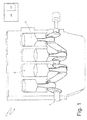
figure 1 , reference numeral 1 indicates as a whole a spark ignited internal combustion engine comprising fourcylinders 2 in a straight arrangement. Eachcylinder 2 comprises arespective piston 3 which is mechanically connected by means of a connecting rod to a drive shaft 4 to transmit the force generated by the combustion incylinder 2 to the drive shaft 4 itself. - As shown in
figure 2 , the internal combustion engine 1 comprises an intake manifold 5, which is connected to eachcylinder 2 by means of two intake valves 6 (of which only one is shown infigure 2 ) and receives fresh air (i.e. air from the outside environment) though a butterfly valve 7 which is moveable between a closing position and a maximum opening position. Furthermore, the internal combustion engine 1 comprises anexhaust manifold 8, which is connected to eachcylinder 2 by means of two exhaust valves 9 (only one of which is shown infigure 2 ) which flows into an emission pipe (not shown) to emit the gases produced in the combustion into the atmosphere. - The position of each exhaust valve 9 is directly controlled by a
camshaft 10 which receives motion from the drive shaft 4; instead, the position of the intake valves 6 is controlled by a valve opening controllingdevice 11 which controls the intake valves 6 by managing the opening angle and lift so as to control the delivered torque by means of the intake valves 6. The valveopening control device 11 uses atraditional camshaft 12 which receives motion from the drive shaft 4 and for each intake valve 6 comprises an electrically controlled hydraulic actuator 13 (i.e. controlled by means of a solenoid valve), which is interposed between a stem of the intake valve 6 and thecamshaft 12. By appropriately controlling eachhydraulic actuator 13, it is possible to adjust the motion transmitted by thecamshaft 12 to the intake valve stem 6, and it is thus possible to adjust the actual lift of the intake valve 6. Thus, the action of thecontrol device 11 allows to vary the actual lift of each intake valve 6 independently from the other intake valves 6, for eachcylinder 2 and engine cycle. - A
corresponding injector 14 is provided for eachcylinder 2; according to the embodiment shown infigure 2 , the injector is of the indirect type and thus eachinjector 14 is arranged upstream of acylinder 2 in an intake pipe which connects the intake manifold 5 tocylinder 2. According to an alternative embodiment (not shown), the injector is of the direct type and thus eachinjector 14 is partially arranged withincylinder 2. - Furthermore, each
cylinder 2 comprises aspark plug 15, which is arranged through the top ofcylinder 2 in central position between the intake valves 5 and the exhaust valves 9 and is cyclically activated to determine the ignition of the compressed gases withincylinder 2 at the end of each compression stroke. - Engine 1 comprises a
control unit 16, which governs the operation of the internal combustion engine 1 and also controls thespark plugs 15 to determine the ignition of the compressed gases in eachcylinder 2. Thecontrol unit 16 comprises amemory 17 in which a series of maps which provide the operating values of thespark plugs 15 as a function of the current engine point are stored; in particular, the maps stored in thememory 17 provide a standard spark advance for each spark plug 15 (i.e. for each cylinder 2). - The method for controlling the detonation in the internal combustion engine 1 which is implemented by the
control unit 16 is described below. - The method for detonation control method which is implemented by the
control unit 16 includes providing an indication of the intensity of the detonation phenomenon in the internal combustion engine 1 by appropriating processing a signal coming from one or more detonation sensors connected to thecontrol unit 16. For example, a detonation sensor arranged to determine the ignition of the compressed gases within eachcylinder 2 is provided for eachspark plug 15. - According to a preferred variant, each detonation sensor comprises a voltage gauge which is connected and arranged in series to the electric circuit of the
spark plug 15 to measure the voltage at the terminals of the electrodes of thespark plug 15 during combustion. - According to a further variant, each detonation sensor comprises a pressure gauge which measures the maximum amplitude pressure oscillation (MAPO) of the intensity of the pressure waves generated in the
cylinders 2 of the internal combustion engine 1 during combustion. - According to a further variant, detonation sensors comprise an accelerometer, which is preferably connected to a motor housing of the internal combustion engine 1.
-
Figure 3 diagrammatically shows the detonation control method which is implemented by thecontrol unit 16, in whichblock 20 receives in input the signal or signals coming from said one or more detonation sensors connected to thecontrol unit 16 and each comprising a respective voltage gauge;block 20 processes the signal or signals coming from said one or more detonation sensors connected to thecontrol unit 16 and then outputs the processed signal to the followingblock 30. - In particular, the signal or signals coming from said one or more detonation sensors connected to the
control unit 16 is or are sampled at a constant frequency determined during a preliminary adjustment and set up phase. According to a preferred variant, such a sampling frequency is equal to 50 kHz. According to a preferred variant, when at least two detonation sensors are provided, the sampling frequency assumes the same value for all the detonation sensors. Once the signal coming from said one or more detonation sensors connected to thecontrol unit 16 has been sampled, an alternating signal which is then rectified is obtained. The rectified signal is further processed to be transmitted to block 30. - According to a first variant, the derivative is calculated from the rectified signal and thus transmitted
block 30. The derivative action of the rectified signal has the drawback of making the detonation control method which is implemented by thecontrol unit 16 excessively sensitive to variations of the signal itself. - According to a second preferred variant, the integral is calculated from the rectified signal and thus transmitted to block 30. The integral action on the rectified signal allows the detonation control method implemented by the
control unit 16 to store the passed values of the signal. As shown infigure 3 , the integrated signal is then transmitted to block 30. - It is equally worth emphasizing that the integrated signal which is transmitted to
block 30 simply represents the combustion energy. Such a combustion energy clearly depends oncylinder 2 and on the engine point in which the combustion is being observed because the signal comes from a detonation sensor, which is connected to the electric circuit of arespective spark plug 15 to measure the voltage at the terminals of the electrodes of thespark plug 15 itself during combustion in a given engine point of therespective cylinder 2. - It has been empirically found that the detonation energy of each combustion taken into account (i.e. for the
cylinder 2 taken into account in a given engine point) is variable between a zero value, which indicates complete absence of detonation, and a maximum value, which indicates a completely detonating combustion. In particular, the detonation energy of each combustion taken into account (i.e. for thecylinder 2 taken into account in a given engine point) assumes a log-normal distribution χ2. Such a log-normal distribution χ2 may be distorted by means of a mathematical device (i.e. by applying a logarithmic curve) and is transformed into a Gaussian or normal distribution, characterized by a mean value µ1 and a standard deviation σ1. - Obviously, the log-normal distribution χ2 is simply the probability distribution of an aleatory variable the logarithm of which follows a normal distribution characterized by a mean value µ1 and by a standard deviation σ1.
-
Block 30 is thus prepared to receive in input the log-normal distribution χ2 of the detonation energy for each combustion taken into account (i.e. for thecylinder 2 taken into account in a given engine point) and process it so as to output the normal distribution of the detonation energy for each combustion taken into account (i.e. for thecylinder 2 taken into account in a given engine point). - The processing of
block 30 of the log-normal distribution χ2 of the detonation energy in each combustion taken into account (i.e. for thecylinder 2 taken into account in a given engine point) is calculated because the mean value µ1 and the standard deviation σ1 are independent in the normal distribution although they both depend on the engine point. - In particular, the normal distribution of the detonation energy of each combustion taken into account (i.e. for the
cylinder 2 taken into account in a given engine point) is characterized by a mean value µi and by a standard deviation σi. - The mean value µi is the nominal noise contribution of the combustion taken into account (i.e. for the
cylinder 2 taken into account in the current engine point). In other words, the mean value µi is the energy, i.e. the mean noise, of the combustion taken into account (i.e. for thecylinder 2 in the current engine point). - Standard deviation σi is determined instead by the cyclic variability, including incorrect combustion phenomena (misfire, detonation etc.). In other words, the deviation of the value of the i-th combustion from the mean value allows to identify the trend or predisposition to detonate of the combustion taken into account (i.e. for the
cylinder 2 in the current engine point). - It is immediately apparent that correctly determining the mean value µi (i.e. the nominal noise contribution of the combustion taken into account, i.e. for the
cylinder 2 taken into account in the current engine point) and the standard deviation σi (i.e. the trend or predisposition to detonate of the combustion taken into account, i.e. for thecylinder 2 taken into account in the current engine point) are at the heart of the method for controlling detonation in the internal combustion engine 1 which is implemented by thecontrol unit 16. -
Block 30 thus provides a representative value of the overall noise (mean nominal noise +/- noise due to specific combustion cycle phenomena which occurred for thecylinder 2 taken into account and in the current engine point, which are impossible to separate beforehand from the mean nominal noise). In other words, block 30 provides the overall combustion energy µi of the i-th combustion taken into account for thecylinder 2 taken into account in the current engine point. - The combustion energy µi of the i-th combustion taken into account for the
cylinder 2 taken into account in the currentengine point block 30 output fromblock 40 is transmitted and inputted into ablock 40 which is suited to determine the average combustion energy µi_m for thecylinder 2 taken into account in the current engine point. -
Block 40 is simply a filter, preferably of the lowpass type. According to a preferred variant, such filter is a first order filter. Also in this case, it is apparent that a correct determination of the constant k filter inblock 40 is a fundamental aspect of the method for controlling the detonation in the internal combustion engine 1 which is implemented by thecontrol unit 16. The constant k filter must indeed result from the trade-off between the need of independence of the single i-th combustion taken into account for thecylinder 2 taken into account in the current engine point and the capacity of the filter itself to react to changes of conditions, i.e. the capacity of the filter itself to adapt to variations of thecylinder 2 taken into account and current engine point (in yet other words, the filter must not be excessively "deaf" to variations of thecylinder 2 taken into account and current engine point). - A group of maps MAPS1 are stored in the
control unit 16. According to a preferred variant, the group of maps MAPS1 comprises a map MAPS1 for eachcylinder 2 of the internal combustion engine 1. In turn, each map MAPS1 for eachcylinder 2 of the internal combustion engine 1 comprises a variable number of cells as a function of the engine points which may be explored during the running of the internal combustion engine 1. Each map MAPS1 for eachcylinder 2 of the internal combustion engine 1 comprises a number of cells univocally identified by the number of revolutions per minute (rpm) and the load. - The filtered value of the combustion energy µi of the i-th combustion taken into account for the
cylinder 2 taken into account in the current engine point output fromblock 40 is used to update the corresponding cell in the group of maps MAPS1; i.e. the filtered value is used to update the map MAPS1 of thecylinder 2 taken into account in its i-th combustion in the current engine point defined by the number of revolutions per minute (rpm) and the load (load). - The updating of the cell in the group of maps MAPS1 is obtained by means of a weighted mean between the value already stored in said cell in the group of maps MAPS1 and the filtered value of the combustion energy µi in the i-th combustion taken into account for the
cylinder 2 taken into account in the current engine point output fromblock 40. - The mean combustion energy µi_m for the
cylinder 2 taken into account in the current engine point is thus obtained by means of the weighted mean of the value already stored in the cell in the group of maps MAPS1 and the filtered value of the combustion energy µi in the i-th combustion taken into account and is made so that by updating the cell in the group of maps µi the filtered value of the combustion energy of the i-th combustion taken into account assumes a gradually decreasing value. In other words, the more i-th combustions in thecylinder 2 taken into account in the current engine point from which the combustion energy µi (i.e. its nominal noise) was derived, the more relevant will be the contribution of the filtered value of the combustion energy µi of the n-th combustion taken into account and the higher will be the contribution of the value already stored in the cell in the group of maps MAPS1. - For this purpose, a group of maps MAPS2 are also stored in the
control unit 16. According to a preferred variant, the structure of the group of maps MAPS2 is identical to the structure of the group of maps MAPS1. - In other words, according to a preferred variant, the group of maps MAPS2 comprises a map MAPS2 for each
cylinder 2 of the internal combustion engine 1; i.e. a respective map MAPS1 of the group of maps MAPS1 is associated to each map MAPS2. Furthermore, in turn, each map MAPS2 for eachcylinder 2 of the internal combustion engine 1 comprises a variable number of cells as a function of the engine points which may be explored during the running of the internal combustion engine 1. Each map MAPS2 for eachcylinder 2 of the internal combustion engine 1 comprises a number of cells univocally identified by the number of revolutions per minute (rpm) and the load (load). Also in this case, each cell which identifies an engine point in the maps MAPS2 thus corresponds to a respective cell which identifies the same engine point in the MAPS1. - The group of maps MAPS2 comprises counters of the number of combustions taken into account during the life of the internal combustion engine 1 for the
corresponding cylinder 2 and in a given engine point in the cells. - The counters in the cells of the group of maps MAPS2 are initialized in a preliminary adjustment and set up phase of the
control unit 16. According to a preferred embodiment, the initialization values of the counters in the cells of the group of maps MAPS2 are variable as a function of thecylinder 2 and/or engine point taken into account. - Furthermore, a lower saturation value is also determined during a preliminary adjustment and set up phase. According to a preferred embodiment, the lower saturation value is variable as a function of the
cylinder 2 and/or engine point taken into account. - In use, when a combustion is observed during the life of the internal combustion engine 1 for a given
cylinder 2 and in a given engine point, the corresponding counter of the cell of the group of maps MAPS2 which corresponds to that givencylinder 2 and that given engine point is decreased by one unit. - As the number of combustions observed during the life of the internal combustion engine 1 for a given
cylinder 2 and in a given engine point (i.e. as the counter in the cell of the group of maps MAPS2 which corresponds to that givencylinder 2 and that given engine point decreases) the weight of the value already stored in the cell in the group of maps MAPS1 increases and therefore the weight of the filtered value of the combustion energy µi of the i-th combustion taken into account is reduced. - In the weighted mean between the value already stored in the cell in the group of maps MAPS1 and the filtered value of the combustion energy µi of the i-th combustion taken into account, the values of the weights are thus variable during the life of the internal combustion engine 1, in particular as a function of the counter in the cell of the group of maps MAPS2 which corresponds to that given
cylinder 2 and that given engine point. - According to a first variant, since the corresponding counter in the cell of the group of maps MAPS2 which corresponds to a given
cylinder 2 and to a given engine point is decreased by one unit for a givencylinder 2 and a given engine point when a combustion is observed during the life of the internal combustion engine 1, the condition may be reached in which the counter is zero and so the filtered value of the combustion energy µi of the i-th combustion taken into account is no longer taken into consideration; in other words, the mean combustion energy µi of the i-th combustion taken into account for thecylinder 2 taken into account in the current engine point is equal to the value already stored in the cell in the group of maps MAPS1. - According to a second preferred variant, the corresponding counter in the cell of the group of maps MAPS2 which corresponds to that given
cylinder 2 and to that given engine point is decreased by one unit until the corresponding lower saturation value is reached when a combustion is observed during the life of the internal combustion engine 1 for a givencylinder 2 and in a given engine point. Once the counter has reached the corresponding lower saturation value it is no longer decreased but maintained constant at the lower saturation value. Thereby, it is not possible to reach the condition in which the filtered value of the combustion energy µi of the i-th combustion taken into account is not considered. And thereby, the mean combustion µi of the i-th combustion taken into account for thecylinder 2 taken into account in the current engine point will continue to be equal to the weighted mean between the value already stored in the cell in the group of maps MAPS1 and the filtered value of the combustion energy µi of the i-th combustion taken into account; wherein the value already stored in the cell in the group of maps MAPS1 will have a predominant weight and the filtered value of the combustion energy µi of the i-th combustion taken into account will have a reduced weight. -
Block 40 thus outputs the mean combustion energy µi_m for thecylinder 2 taken into account in the current engine point which is transmitted and inputted to ablock 50.Block 50 thus receives in input both the mean combustion energy µi_m for thecylinder 2 taken into account in the currentengine point block 40 and the combustion energy µi of the i-th combustion taken into account for thecylinder 2 taken into account in the current engine point byblock 30.Block 50 is further suited to compare the mean combustion energy value µi_m for thecylinder 2 taken into account in the current engine point with the combustion energy µi of the i-th combustion taken into account for thecylinder 2 taken into account in the current engine point. - Thereby, block 50 can establish by how much the combustion energy µi of the i-th combustion taken into account for the
cylinder 2 taken into account in the current engine point differs from the mean combustion energy µi_m for thecylinder 2 taken into account in the current engine point.Block 50 thus determines the deviation of the i-th combustion taken into account for thecylinder 2 taken into account in the current engine point, which represents the cyclic variability, i.e. the tendency or predisposition to detonate of the i-th combustion taken into account for thecylinder 2 taken into account in the current engine point. -
Block 50 thus outputs the deviation of the i-th combustion taken into account for thecylinder 2 taken into account in the current engine point which is transmitted and inputted into ablock 60.Block 60 receives in input both the deviation of the i-th combustion taken into account for thecylinder 2 taken into account in the current engine point fromblock 50 and the maximum tolerable deviation for thecylinder 2 taken into account in the current engine point. - Furthermore, block 60 is suited to compare the deviation of the i-th combustion taken into account for the
cylinder 2 taken into account in the current engine point with the maximum deviation for thecylinder 2 taken into account in the current engine point. - The method for determining the maximum standard deviation σi_MAX for each
cylinder 2 for each engine point explored during the operation of the internal combustion engine 1 is described below. - The
control unit 16 is suited to implement an "intrusive" strategy for controlling the spark advance according to which the standard spark provided by the engine control by means of themaps 17 for eachcylinder 2 in each engine point is degraded to be placed into the conditions in which the generation of detonation phenomena will not occur. Typically, such an "intrusive" strategy thus includes reducing the actuated spark advance until it is placed in the conditions in which certainly no detonation phenomena will occur for eachcylinder 2 in each engine point. - A group of maps MAPS3 are stored in the
control unit 16. According to a preferred variant, the group of maps MAPS3 comprises a map MAPS3 for eachcylinder 2 of the internal combustion engine 1. In turn, each map MAPS3 for eachcylinder 2 of the internal combustion engine 1 comprises a variable number of cells as a function of the engine points which may be explored during running of the internal combustion engine 1. Each map MAPS3 for eachcylinder 2 of the internal combustion engine 1 comprises a number of cells univocally identified by the number of revolutions per minute (rpm) and the load). - A group of maps MAPS4 are also stored in the
control unit 16. According to a preferred variant, the structure of the group of maps MAPS4 is identical to the structure of the group of maps MAPS3. - In other words, according to a preferred variant, the group of maps MAPS4 comprises a map MAPS4 for each
cylinder 2 of the internal combustion engine 1; i.e. a respective map MAPS3 of the group of maps MAPS3 is associated to each map MAPS4. Furthermore, in turn, each map MAPS4 for eachcylinder 2 of the internal combustion engine 1 comprises a variable number of cells as a function of the engine points which may be explored during running of the internal combustion engine 1. Each map MAPS4 for eachcylinder 2 of the internal combustion engine 1 comprises a number of cells univocally identified by the number of revolutions per minute (rpm) and the load (load). Also in this case, each cell which identifies an engine point in the maps MAPS4 corresponds to a respective cell which identifies the same engine point in the MAPS3. - The group of maps MAPS4 comprises in the cells counters of the number of combustions taken into account during the life of the internal combustion engine 1 for the
corresponding cylinder 2 and in a given engine point. - The counters in the cells of the group of maps MAPS4 are initialized in a preliminary adjustment and set up phase of the
control unit 16. According to a preferred embodiment, the initialization values of the counters in the cells of the group of maps MAPS4 are variable as a function of thecylinder 2 and/or the engine point taken into account. In use, when a combustion is observed during the life of the internal combustion engine 1 for a givencylinder 2 and in a given engine point, the corresponding counter in the cell in the group of maps MAPS4 which corresponds to that givencylinder 2 and that given engine point is decreased by one unit. - Because the
control unit 16 is suited to actuate a spark advance for eachcylinder 2 in each engine point in order to avoid the generation of detonation phenomena, a number of combustions can be observed for thecylinder 2 taken into account in the current engine point equal to the corresponding counter in the cell of the group of maps MAPS4 which corresponds to that givencylinder 2 and that given engine point in which detonation phenomena will certainly not occur. - For each i-th combustion taken into account for the
cylinder 2 taken into account in the current engine point it is possible to analyze the signal of the i-th combustion itself taken into account and, in particular, it is possible to learn the nominal value of the noise peak of the i-th combustion taken into account for thecylinder 2 taken into account in the current engine point (with respect to the previous ones, from the starting instant of the learning procedure) to determine the maximum standard deviation σi_MAX for thecylinder 2 taken into account in the current engine point. - The nominal value of the noise peak of the i-th combustion taken into account for the
cylinder 2 taken into account in the current engine point is used to update the corresponding cell in the group of maps MAPS3; i.e. the nominal value of the noise peak of the i-th combustion taken into account for thecylinder 2 taken into account in the current engine point is used to update the map MAPS3 of thecylinder 2 taken into account in the current engine point defined by the number of revolutions per minute (rpm) and by the load (load). - The updating of the cell in the group of maps MAPS3 is obtained by means of a weighted mean between the value already stored in the said cell in the group of maps MAPS3 and the nominal value of the noise peak value of the i-th combustion taken into account for the
cylinder 2 taken into account in the current engine point. - The weighted mean between the value already stored in the cell in the group of maps MAPS3 and the nominal value of the noise peak of the i-th combustion taken into account for the
cylinder 2 taken into account in the current engine point (with respect to the previous ones, from the starting instant of the learning procedure) is made so that the nominal value of the noise peak of the i-th combustion taken into account for thecylinder 2 taken into account in the current engine point has a gradually increasing weight. In other words, the more i-th combustions of thecylinder 2 taken into account in the current engine point in which the combustion energy µi (i.e. its nominal noise) can be observed, the more relevant will be the contribution of the nominal value of the noise peak of the i-th combustion taken into account for thecylinder 2 taken into account in the current engine point and the more relevant will be the contribution of the value already stored in the respective cell of the group of maps MAPS3. - As the number of combustions observed during the life internal combustion engine 1 for given
cylinder 2 and given engine point (i.e. as the counter in the cell of the group of maps MAPS4 which corresponds to that givencylinder 2 and that given engine point) decreases, the weight of the nominal value of the noise peak of the i-th combustion taken into account for thecylinder 2 taken into account in the current engine point increases. - In the weighted mean of the value already stored in the cell in the group of maps MAPS3 and the nominal value of the noise peak of the i-th combustion taken into account for the
cylinder 2 in the current engine point, the values of the weights are thus variable during the step of learning of the internal combustion engine 1, in particular as a function of the counter in the cell of the group of maps MAPS4 which corresponds to that givencylinder 2 and that given engine point. - According to a first variant, since the corresponding counter in the cell of the group of maps MAPS4 which corresponds to a given
cylinder 2 and to a given engine point is decreased by one unit when a combustion is observed during the life of the internal combustion engine 1 for that givencylinder 2 and that given engine point, the condition is reached in which the counter is zero and the learning phase may be said to be concluded. - However, since reducing the spark advance in a
cylinder 2 corresponds to a loss of thermodynamic efficiency in terms of combustion efficiency as the air mass forcylinder 2, and thus the injected gasoline mass as well, are maintained constant, but the fraction of chemical energy converted into mechanical energy is reduced and because the learning phase for each cylinder is rather long, according to a preferred variant the learning step is carried out on one cylinder at a time to avoid negative repercussions on fuel consumption and on the generation of polluting substances. -
Block 60 thus receives in input both the standard deviation σi of the i-th combustion taken into account for thecylinder 2 taken into account in the current engine point fromblock 50 and the maximum standard deviation σi_MAX for thecylinder 2 taken into account in the current engine point. Furthermore, block 60 is provided to compare the standard deviation σi of the i-th combustion taken into account for thecylinder 2 taken into account in the current engine point with the maximum standard deviation σi_MAx for thecylinder 2 taken into account in the current engine point. Furthermore, block 60 is suited to determine the development of detonation phenomena as a function of the comparison of the standard deviation σi of the i-th combustion taken into account for thecylinder 2 taken into account in the current engine point (which also represents the tendency to detonate of the i-th combustion taken into account for thecylinder 2 taken into account in the current engine point) with the maximum standard deviation σi_MAX for thecylinder 2 taken into account in the current engine point. - In the description above, the size of the maps indicated by MAPS1, MAPS2, MAPS3 and MAPS4 respectively depend on the number of cylinders (ncyl) and from the engine point, i.e. on the number of revolutions per minute (rpm) and the load (load).
- Furthermore, according to a first variant, the
control unit 16 is suited to re-initialize the groups of maps indicated by MAPS1, MAPS2, MAPS3 and MAPS4 respectively at the ignition events of thecontrol unit 16. - According to a possible variant, the counters in the cells of the group of maps MAP2 and of the group of maps MAPS4 are initialized in a preliminary adjustment and set up phase of the
control unit 16 to zero values. Furthermore, the upper saturation values are determined in a preliminary adjustment and set up phase. According to a preferred embodiment, the upper saturation values are variable as a function of thecylinder 2 and/or the engine point taken into account. In use, the corresponding counter in the respective cell of a group of maps MAPS2 and in the respective cell of the group of maps MAPS4 which corresponds to a givencylinder 2 and that a engine point is increased by one unit until the upper saturation value is reached when a combustion is observed during the life of the internal combustion engine 1 for that givencylinder 2 and in that given engine point. - Il sopra descritto metodo di controllo della detonazione presenta numerosi vantaggi.
- Firstly, the above-described control method is applied individually to each
cylinder 2, so that the inevitable differences which exist between the various cylinders due to the effect of construction tolerances and of the temperature differences of the walls of the cylinders due to the different positions ofcylinders 2 in the internal combustion engine 1 may be taken into consideration. - Secondly, the above-described control method is simple and cost-effective to implement in an electronic control unit of an internal combustion engine 1 because it does not require any physical modifications and employs a low calculation capacity of the control unit 6.
- Furthermore, the above-described detonation control method allows to recognize the development of detonation phenomena effectively and keep the detonation in the
various cylinders 2 under control without noticeable negative effects on combustion thermodynamic efficiency which is maintained close to the maximum possible values with evident benefits on consumptions and pollution containment.
Claims (12)
- A method for detecting the development of detonation phenomena in an internal combustion engine (1) provided with a number of cylinders (2), a control unit (16), and a number of detonation sensors connected to the control unit (16); wherein, detonation sensors comprise an accelerometer and/or a voltage gauge which is connected and arranged in series to the electric circuit of a spark plug (15) to measure the voltage at the terminals of the electrodes of the spark plug (15) during combustion and/or a pressure gauge which measures the maximum amplitude pressure oscillation (MAPO) of the intensity of the pressure waves generated in the cylinders (2) during combustion; the method comprises the steps of:acquiring the signal (S) coming from said number of detonation sensors connected to the control unit (16);processing the signal (S) coming from said number of detonation sensors connected to the control unit (16) so as to obtain the detonation energy (µi) of each combustion taken into account for a given cylinder (2) and in a given engine point;filtering the detonation energy (µi) of each combustion taken into account for a given cylinder (2) and in a given engine point;calculating the mean detonation energy (µi_m) for a given cylinder (2) and in a given engine point by means of the filtered value of the detonation energy (µi) of each combustion taken into account for a given cylinder (2) and in a given engine point;comparing the detonation energy (µi) of each combustion taken into account for a given cylinder (2) and in a given engine point with the mean detonation energy (µi_m) for a given cylinder (2) and in a given engine point;characterized in that the method additionally comprises the steps of :determining the variance (σi) of each combustion taken into account for a given cylinder (2) and in a given engine point as a function of the comparison between the detonation energy (µi) of each combustion taken into account for a given cylinder (2) and in a given engine point and the mean detonation energy (µi_m) for a given cylinder (2) and in a given engine point;calculating the maximum variance (σi_max) for a given cylinder (2) and in a given engine point by means of a reduction of the spark advance actuated in the given cylinder (2) ;comparing the maximum variance (σi_max) for a given cylinder (2) and in a given engine point with the variance (σi) of each combustion taken into account for a given cylinder (2) and in a given engine point; anddetermining the development of detonation phenomena for each combustion taken into account for a given cylinder (2) and in a given engine point as a function of the comparison between the maximum variance (σi_max) for a given cylinder (2) and in a given engine point and the variance (σi) of each combustion taken into account for a given cylinder (2) and in a given engine point.
- A method according to claim 1 and comprising the further steps of:initializing, in a preliminary adjustment and set up phase, a first map (MAPS1) with the values of the mean detonation energy (µi_m) for a given cylinder (2) and in a given engine point; andupdating the first map (MAPS1) with the filtered value of the detonation energy (µi) of each combustion taken into account for a given cylinder (2) and in a given engine point.
- A method according to claim 2 and comprising the further step of updating the first map (MAPS1) with the filtered value of the detonation energy (µi) of each combustion taken into account for a given cylinder (2) and in a given engine point by means of a weighted mean between the filtered value of the detonation energy (µi) of each combustion taken into account for a given cylinder (2) and in a given engine point and the value of the mean detonation energy (µi_m) for a given cylinder (2) and in a given engine point contained in the first map (MAPS1).
- A method according to claim 3 and comprising the further steps of:initializing, in a preliminary adjustment and set up phase, a second map (MAPS2) of counters of the combustions taken into account for a given cylinder (2) and in a given engine point; anddetermining the weights to be assigned to the filtered value of the detonation energy (µi) of each combustion taken into account for a given cylinder (2) and in a given engine point and to the value of the mean detonation energy (µi_m) for a given cylinder (2) and in a given engine point contained in the first map (MAPS1) as a function of the second map (MAPS2) of counters of the combustions taken into account for a given cylinder (2) and in a given engine point.
- A method according to claim 4, wherein the filtered value of the detonation energy (µi) of each combustion taken into account for a given cylinder (2) has a gradually decreasing value.
- A method according to any of the previous claims and comprising the further steps of:initializing, in a preliminary adjustment and set up phase, a third map (MAPS3) with the values of the maximum variance (σi_max) for a given cylinder (2) and in a given engine point; andupdating, during a learning phase, the third map (MAPS3) with the nominal value of the noise peak of the i-th combustion taken into account for a given cylinder (2) and in a given engine point.
- A method according to claim 6 and comprising the further step of updating the third map (MAPS3) with the nominal value of the noise peak of the i-th combustion taken into account for a given cylinder (2) and in a given engine point by means of a weighted mean between the nominal value of the noise peak of the i-th combustion taken into account for a given cylinder (2) and in a given engine point and the value of the maximum variance (σi_max) for a given cylinder (2) and in a given engine point contained in the third map (MAPS3).
- A method according to claim 7 and comprising the further steps of:initializing, in a preliminary adjustment and set up phase, a fourth map (MAPS4) of counters of the combustions taken into account for a given cylinder (2) and in a given engine point; anddetermining the weights to be assigned to the nominal value of the noise peak of the i-th combustion taken into account for a given cylinder (2) and in a given engine point and to the value of the maximum variance (σi_max) for a given cylinder (2) and in a given engine point contained in the third map (MAPS3) as a function of the fourth map (MAPS4) of counters of the combustions taken into account for a given cylinder (2) and in a given engine point.
- A method according to claim 8, wherein the nominal value of the noise peak of the i-th combustion taken into account for a given cylinder (2) and in a given engine point has a gradually increasing value.
- A method according to any of the claims from 2 to 9, wherein the first map (MAPS1) and/or the second map (MAPS2) and/or the third map (MAPS3) and/or the fourth map (MAPS4) have a number of cells that varies as a function of the number (Ncyl) of cylinders (2) and of the engine points identified by the number of revolutions per minute (rpm) and by the load (load).
- A method according to any of the previous claims, wherein the step of calculating the maximum variance (σi_max) for a given cylinder (2) and in a given engine point by means of a reduction of the spark advance actuated in the given cylinder (2) is performed by degrading the spark advance actuated in the given cylinder (2) up to a value that is such that no detonation phenomena will occur.
- An electronic control unit (16), which is suited to implement a method for detecting the development of detonation phenomena in an internal combustion engine (1) performed according to one or more of the claims from 1 to 11.
Applications Claiming Priority (1)
| Application Number | Priority Date | Filing Date | Title |
|---|---|---|---|
| IT000224A ITBO20130224A1 (en) | 2013-05-14 | 2013-05-14 | METHOD FOR RECOGNIZING DENONATION PHENOMENA IN AN INTERNAL COMBUSTION ENGINE |
Publications (2)
| Publication Number | Publication Date |
|---|---|
| EP2803966A1 EP2803966A1 (en) | 2014-11-19 |
| EP2803966B1 true EP2803966B1 (en) | 2016-07-06 |
Family
ID=48877314
Family Applications (1)
| Application Number | Title | Priority Date | Filing Date |
|---|---|---|---|
| EP14168371.4A Active EP2803966B1 (en) | 2013-05-14 | 2014-05-14 | Method for detecting detonation phenomena in an internal combustion engine |
Country Status (6)
| Country | Link |
|---|---|
| US (1) | US9322382B2 (en) |
| EP (1) | EP2803966B1 (en) |
| CN (1) | CN104153931B (en) |
| BR (1) | BR102014011542B1 (en) |
| IN (1) | IN2014DE01277A (en) |
| IT (1) | ITBO20130224A1 (en) |
Families Citing this family (4)
| Publication number | Priority date | Publication date | Assignee | Title |
|---|---|---|---|---|
| US9429096B2 (en) * | 2011-09-15 | 2016-08-30 | Robert Bosch Gmbh | Predictive modeling and reducing cyclic variability in autoignition engines |
| AT518149B1 (en) * | 2015-12-29 | 2018-07-15 | Ge Jenbacher Gmbh & Co Og | Internal combustion engine |
| CN110878718B (en) * | 2019-12-31 | 2022-04-19 | 广西玉柴机器股份有限公司 | Detonation control method of natural gas engine |
| CN118066570B (en) * | 2024-04-17 | 2024-07-12 | 中国空气动力研究与发展中心空天技术研究所 | Stamping rotary detonation combustion chamber capable of realizing PLIF optical observation of circular section flow passage |
Family Cites Families (9)
| Publication number | Priority date | Publication date | Assignee | Title |
|---|---|---|---|---|
| US5386722A (en) * | 1993-03-24 | 1995-02-07 | Ford Motor Company | Method and apparatus for statistically determining knock borderline and evaluating knock intensity in an internal combustion engine |
| JP3715847B2 (en) * | 1999-09-20 | 2005-11-16 | 三菱電機株式会社 | Knock control device for internal combustion engine |
| JP3827083B2 (en) * | 2002-11-08 | 2006-09-27 | 三菱電機株式会社 | Knock detection device for internal combustion engine |
| FR2854693B1 (en) * | 2003-05-09 | 2005-07-01 | Siemens Vdo Automotive | METHOD FOR DETERMINING THE ENERGY OF A CLICKING SIGNAL FOR AN INTERNAL COMBUSTION ENGINE |
| JP4397804B2 (en) * | 2004-12-27 | 2010-01-13 | 本田技研工業株式会社 | Knock detection device |
| FR2898411B1 (en) * | 2006-03-08 | 2008-05-16 | Inst Francais Du Petrole | REAL-TIME ESTIMATION METHOD OF ENGINE COMBUSTION PARAMETERS FROM VIBRATORY SIGNALS |
| ITBO20090308A1 (en) * | 2009-05-13 | 2010-11-14 | Magneti Marelli Spa | METHOD OF CHECKING DETONATION IN AN INTERNAL COMBUSTION ENGINE |
| JP5762021B2 (en) * | 2011-01-31 | 2015-08-12 | 三菱電機株式会社 | Engine knock control device |
| JP2013068160A (en) * | 2011-09-22 | 2013-04-18 | Suzuki Motor Corp | Knocking control device of engine |
-
2013
- 2013-05-14 IT IT000224A patent/ITBO20130224A1/en unknown
-
2014
- 2014-05-13 IN IN1277DE2014 patent/IN2014DE01277A/en unknown
- 2014-05-13 US US14/276,385 patent/US9322382B2/en active Active
- 2014-05-13 BR BR102014011542-0A patent/BR102014011542B1/en active IP Right Grant
- 2014-05-14 CN CN201410204327.0A patent/CN104153931B/en active Active
- 2014-05-14 EP EP14168371.4A patent/EP2803966B1/en active Active
Also Published As
| Publication number | Publication date |
|---|---|
| EP2803966A1 (en) | 2014-11-19 |
| CN104153931A (en) | 2014-11-19 |
| BR102014011542A2 (en) | 2016-08-23 |
| US20140338433A1 (en) | 2014-11-20 |
| CN104153931B (en) | 2018-03-27 |
| BR102014011542B1 (en) | 2022-02-22 |
| ITBO20130224A1 (en) | 2014-11-15 |
| IN2014DE01277A (en) | 2015-06-12 |
| US9322382B2 (en) | 2016-04-26 |
Similar Documents
| Publication | Publication Date | Title |
|---|---|---|
| US7681552B2 (en) | Internal combustion engine knock determination device and knock determination method | |
| US6748922B2 (en) | Knock control apparatus for internal combustion engine | |
| CN107429630B (en) | The control device and abnormal combustion detection method of internal combustion engine | |
| EP2803966B1 (en) | Method for detecting detonation phenomena in an internal combustion engine | |
| US8005607B2 (en) | Device and method for controlling ignition timing of internal combustion engine | |
| US7478622B2 (en) | Device and method for determining knocking of internal combustion engine | |
| US20150159569A1 (en) | Method and apparatus for detecting combustion phase of engine by angular acceleration signal and combustion data of single cylinder | |
| US20100031923A1 (en) | Method and Apparatus for Detecting Engine Knock | |
| US8924134B2 (en) | Knock control device of internal combustion engine | |
| US10451024B2 (en) | Internal combustion engine abnormal combustion detection device | |
| EP3369918A1 (en) | Control device for internal combustion engine | |
| EP3109457B1 (en) | Ignition device and ignition method for internal combustion engine | |
| CN103174536A (en) | Knock control apparatus for internal combustion engine | |
| JP2013147948A (en) | Internal combustion engine control device | |
| EP3139023B1 (en) | Method for detecting the anti-knocking capacity of a fuel in an internal combustion engine | |
| JPS6262225A (en) | Knocking detection for internal combustion engine | |
| CN107701321A (en) | The method of the generation for the phenomenon that misfired in identification explosive motor cylinder | |
| EP3023621B1 (en) | Method to detect and control detonation phenomena in an internal combustion engine | |
| JP6252201B2 (en) | Abnormal combustion detector | |
| JPH04101051A (en) | Misfire detecting device and method for internal combustion engine |
Legal Events
| Date | Code | Title | Description |
|---|---|---|---|
| PUAI | Public reference made under article 153(3) epc to a published international application that has entered the european phase |
Free format text: ORIGINAL CODE: 0009012 |
|
| 17P | Request for examination filed |
Effective date: 20140514 |
|
| AK | Designated contracting states |
Kind code of ref document: A1 Designated state(s): AL AT BE BG CH CY CZ DE DK EE ES FI FR GB GR HR HU IE IS IT LI LT LU LV MC MK MT NL NO PL PT RO RS SE SI SK SM TR |
|
| AX | Request for extension of the european patent |
Extension state: BA ME |
|
| R17P | Request for examination filed (corrected) |
Effective date: 20150519 |
|
| GRAP | Despatch of communication of intention to grant a patent |
Free format text: ORIGINAL CODE: EPIDOSNIGR1 |
|
| INTG | Intention to grant announced |
Effective date: 20151216 |
|
| GRAS | Grant fee paid |
Free format text: ORIGINAL CODE: EPIDOSNIGR3 |
|
| GRAA | (expected) grant |
Free format text: ORIGINAL CODE: 0009210 |
|
| AK | Designated contracting states |
Kind code of ref document: B1 Designated state(s): AL AT BE BG CH CY CZ DE DK EE ES FI FR GB GR HR HU IE IS IT LI LT LU LV MC MK MT NL NO PL PT RO RS SE SI SK SM TR |
|
| REG | Reference to a national code |
Ref country code: GB Ref legal event code: FG4D |
|
| REG | Reference to a national code |
Ref country code: AT Ref legal event code: REF Ref document number: 811057 Country of ref document: AT Kind code of ref document: T Effective date: 20160715 Ref country code: CH Ref legal event code: EP |
|
| REG | Reference to a national code |
Ref country code: IE Ref legal event code: FG4D |
|
| REG | Reference to a national code |
Ref country code: DE Ref legal event code: R096 Ref document number: 602014002550 Country of ref document: DE |
|
| REG | Reference to a national code |
Ref country code: NL Ref legal event code: MP Effective date: 20160706 |
|
| REG | Reference to a national code |
Ref country code: LT Ref legal event code: MG4D |
|
| REG | Reference to a national code |
Ref country code: AT Ref legal event code: MK05 Ref document number: 811057 Country of ref document: AT Kind code of ref document: T Effective date: 20160706 |
|
| PG25 | Lapsed in a contracting state [announced via postgrant information from national office to epo] |
Ref country code: LT Free format text: LAPSE BECAUSE OF FAILURE TO SUBMIT A TRANSLATION OF THE DESCRIPTION OR TO PAY THE FEE WITHIN THE PRESCRIBED TIME-LIMIT Effective date: 20160706 Ref country code: FI Free format text: LAPSE BECAUSE OF FAILURE TO SUBMIT A TRANSLATION OF THE DESCRIPTION OR TO PAY THE FEE WITHIN THE PRESCRIBED TIME-LIMIT Effective date: 20160706 Ref country code: RS Free format text: LAPSE BECAUSE OF FAILURE TO SUBMIT A TRANSLATION OF THE DESCRIPTION OR TO PAY THE FEE WITHIN THE PRESCRIBED TIME-LIMIT Effective date: 20160706 Ref country code: HR Free format text: LAPSE BECAUSE OF FAILURE TO SUBMIT A TRANSLATION OF THE DESCRIPTION OR TO PAY THE FEE WITHIN THE PRESCRIBED TIME-LIMIT Effective date: 20160706 Ref country code: IS Free format text: LAPSE BECAUSE OF FAILURE TO SUBMIT A TRANSLATION OF THE DESCRIPTION OR TO PAY THE FEE WITHIN THE PRESCRIBED TIME-LIMIT Effective date: 20161106 Ref country code: NL Free format text: LAPSE BECAUSE OF FAILURE TO SUBMIT A TRANSLATION OF THE DESCRIPTION OR TO PAY THE FEE WITHIN THE PRESCRIBED TIME-LIMIT Effective date: 20160706 Ref country code: NO Free format text: LAPSE BECAUSE OF FAILURE TO SUBMIT A TRANSLATION OF THE DESCRIPTION OR TO PAY THE FEE WITHIN THE PRESCRIBED TIME-LIMIT Effective date: 20161006 |
|
| PG25 | Lapsed in a contracting state [announced via postgrant information from national office to epo] |
Ref country code: AT Free format text: LAPSE BECAUSE OF FAILURE TO SUBMIT A TRANSLATION OF THE DESCRIPTION OR TO PAY THE FEE WITHIN THE PRESCRIBED TIME-LIMIT Effective date: 20160706 Ref country code: GR Free format text: LAPSE BECAUSE OF FAILURE TO SUBMIT A TRANSLATION OF THE DESCRIPTION OR TO PAY THE FEE WITHIN THE PRESCRIBED TIME-LIMIT Effective date: 20161007 Ref country code: PL Free format text: LAPSE BECAUSE OF FAILURE TO SUBMIT A TRANSLATION OF THE DESCRIPTION OR TO PAY THE FEE WITHIN THE PRESCRIBED TIME-LIMIT Effective date: 20160706 Ref country code: ES Free format text: LAPSE BECAUSE OF FAILURE TO SUBMIT A TRANSLATION OF THE DESCRIPTION OR TO PAY THE FEE WITHIN THE PRESCRIBED TIME-LIMIT Effective date: 20160706 Ref country code: SE Free format text: LAPSE BECAUSE OF FAILURE TO SUBMIT A TRANSLATION OF THE DESCRIPTION OR TO PAY THE FEE WITHIN THE PRESCRIBED TIME-LIMIT Effective date: 20160706 Ref country code: PT Free format text: LAPSE BECAUSE OF FAILURE TO SUBMIT A TRANSLATION OF THE DESCRIPTION OR TO PAY THE FEE WITHIN THE PRESCRIBED TIME-LIMIT Effective date: 20161107 Ref country code: LV Free format text: LAPSE BECAUSE OF FAILURE TO SUBMIT A TRANSLATION OF THE DESCRIPTION OR TO PAY THE FEE WITHIN THE PRESCRIBED TIME-LIMIT Effective date: 20160706 Ref country code: BE Free format text: LAPSE BECAUSE OF FAILURE TO SUBMIT A TRANSLATION OF THE DESCRIPTION OR TO PAY THE FEE WITHIN THE PRESCRIBED TIME-LIMIT Effective date: 20160706 |
|
| REG | Reference to a national code |
Ref country code: DE Ref legal event code: R097 Ref document number: 602014002550 Country of ref document: DE |
|
| REG | Reference to a national code |
Ref country code: FR Ref legal event code: PLFP Year of fee payment: 4 |
|
| PG25 | Lapsed in a contracting state [announced via postgrant information from national office to epo] |
Ref country code: RO Free format text: LAPSE BECAUSE OF FAILURE TO SUBMIT A TRANSLATION OF THE DESCRIPTION OR TO PAY THE FEE WITHIN THE PRESCRIBED TIME-LIMIT Effective date: 20160706 Ref country code: EE Free format text: LAPSE BECAUSE OF FAILURE TO SUBMIT A TRANSLATION OF THE DESCRIPTION OR TO PAY THE FEE WITHIN THE PRESCRIBED TIME-LIMIT Effective date: 20160706 |
|
| PLBE | No opposition filed within time limit |
Free format text: ORIGINAL CODE: 0009261 |
|
| STAA | Information on the status of an ep patent application or granted ep patent |
Free format text: STATUS: NO OPPOSITION FILED WITHIN TIME LIMIT |
|
| PG25 | Lapsed in a contracting state [announced via postgrant information from national office to epo] |
Ref country code: BG Free format text: LAPSE BECAUSE OF FAILURE TO SUBMIT A TRANSLATION OF THE DESCRIPTION OR TO PAY THE FEE WITHIN THE PRESCRIBED TIME-LIMIT Effective date: 20161006 Ref country code: DK Free format text: LAPSE BECAUSE OF FAILURE TO SUBMIT A TRANSLATION OF THE DESCRIPTION OR TO PAY THE FEE WITHIN THE PRESCRIBED TIME-LIMIT Effective date: 20160706 Ref country code: SM Free format text: LAPSE BECAUSE OF FAILURE TO SUBMIT A TRANSLATION OF THE DESCRIPTION OR TO PAY THE FEE WITHIN THE PRESCRIBED TIME-LIMIT Effective date: 20160706 Ref country code: SK Free format text: LAPSE BECAUSE OF FAILURE TO SUBMIT A TRANSLATION OF THE DESCRIPTION OR TO PAY THE FEE WITHIN THE PRESCRIBED TIME-LIMIT Effective date: 20160706 Ref country code: CZ Free format text: LAPSE BECAUSE OF FAILURE TO SUBMIT A TRANSLATION OF THE DESCRIPTION OR TO PAY THE FEE WITHIN THE PRESCRIBED TIME-LIMIT Effective date: 20160706 |
|
| 26N | No opposition filed |
Effective date: 20170407 |
|
| PG25 | Lapsed in a contracting state [announced via postgrant information from national office to epo] |
Ref country code: LU Free format text: LAPSE BECAUSE OF NON-PAYMENT OF DUE FEES Effective date: 20170531 Ref country code: SI Free format text: LAPSE BECAUSE OF FAILURE TO SUBMIT A TRANSLATION OF THE DESCRIPTION OR TO PAY THE FEE WITHIN THE PRESCRIBED TIME-LIMIT Effective date: 20160706 |
|
| PGFP | Annual fee paid to national office [announced via postgrant information from national office to epo] |
Ref country code: TR Payment date: 20170427 Year of fee payment: 4 |
|
| REG | Reference to a national code |
Ref country code: CH Ref legal event code: PL |
|
| PG25 | Lapsed in a contracting state [announced via postgrant information from national office to epo] |
Ref country code: MC Free format text: LAPSE BECAUSE OF FAILURE TO SUBMIT A TRANSLATION OF THE DESCRIPTION OR TO PAY THE FEE WITHIN THE PRESCRIBED TIME-LIMIT Effective date: 20160706 |
|
| REG | Reference to a national code |
Ref country code: IE Ref legal event code: MM4A |
|
| PG25 | Lapsed in a contracting state [announced via postgrant information from national office to epo] |
Ref country code: CH Free format text: LAPSE BECAUSE OF NON-PAYMENT OF DUE FEES Effective date: 20170531 Ref country code: LI Free format text: LAPSE BECAUSE OF NON-PAYMENT OF DUE FEES Effective date: 20170531 |
|
| PG25 | Lapsed in a contracting state [announced via postgrant information from national office to epo] |
Ref country code: LU Free format text: LAPSE BECAUSE OF NON-PAYMENT OF DUE FEES Effective date: 20170514 |
|
| REG | Reference to a national code |
Ref country code: FR Ref legal event code: PLFP Year of fee payment: 5 |
|
| PG25 | Lapsed in a contracting state [announced via postgrant information from national office to epo] |
Ref country code: IE Free format text: LAPSE BECAUSE OF NON-PAYMENT OF DUE FEES Effective date: 20170514 |
|
| PG25 | Lapsed in a contracting state [announced via postgrant information from national office to epo] |
Ref country code: MT Free format text: LAPSE BECAUSE OF NON-PAYMENT OF DUE FEES Effective date: 20170514 |
|
| PG25 | Lapsed in a contracting state [announced via postgrant information from national office to epo] |
Ref country code: AL Free format text: LAPSE BECAUSE OF FAILURE TO SUBMIT A TRANSLATION OF THE DESCRIPTION OR TO PAY THE FEE WITHIN THE PRESCRIBED TIME-LIMIT Effective date: 20160706 |
|
| GBPC | Gb: european patent ceased through non-payment of renewal fee |
Effective date: 20180514 |
|
| PG25 | Lapsed in a contracting state [announced via postgrant information from national office to epo] |
Ref country code: GB Free format text: LAPSE BECAUSE OF NON-PAYMENT OF DUE FEES Effective date: 20180514 |
|
| PG25 | Lapsed in a contracting state [announced via postgrant information from national office to epo] |
Ref country code: HU Free format text: LAPSE BECAUSE OF FAILURE TO SUBMIT A TRANSLATION OF THE DESCRIPTION OR TO PAY THE FEE WITHIN THE PRESCRIBED TIME-LIMIT; INVALID AB INITIO Effective date: 20140514 |
|
| PG25 | Lapsed in a contracting state [announced via postgrant information from national office to epo] |
Ref country code: CY Free format text: LAPSE BECAUSE OF FAILURE TO SUBMIT A TRANSLATION OF THE DESCRIPTION OR TO PAY THE FEE WITHIN THE PRESCRIBED TIME-LIMIT Effective date: 20160706 |
|
| PG25 | Lapsed in a contracting state [announced via postgrant information from national office to epo] |
Ref country code: MK Free format text: LAPSE BECAUSE OF FAILURE TO SUBMIT A TRANSLATION OF THE DESCRIPTION OR TO PAY THE FEE WITHIN THE PRESCRIBED TIME-LIMIT Effective date: 20160706 |
|
| PG25 | Lapsed in a contracting state [announced via postgrant information from national office to epo] |
Ref country code: TR Free format text: LAPSE BECAUSE OF NON-PAYMENT OF DUE FEES Effective date: 20180514 |
|
| PGFP | Annual fee paid to national office [announced via postgrant information from national office to epo] |
Ref country code: DE Payment date: 20240418 Year of fee payment: 11 |
|
| PGFP | Annual fee paid to national office [announced via postgrant information from national office to epo] |
Ref country code: IT Payment date: 20240418 Year of fee payment: 11 Ref country code: FR Payment date: 20240418 Year of fee payment: 11 |