EP2803837A1 - Supercharging system and method for controlling supercharging system - Google Patents
Supercharging system and method for controlling supercharging system Download PDFInfo
- Publication number
- EP2803837A1 EP2803837A1 EP13735573.1A EP13735573A EP2803837A1 EP 2803837 A1 EP2803837 A1 EP 2803837A1 EP 13735573 A EP13735573 A EP 13735573A EP 2803837 A1 EP2803837 A1 EP 2803837A1
- Authority
- EP
- European Patent Office
- Prior art keywords
- temperature
- turbocharger
- electrically
- target temperature
- wastegate valve
- Prior art date
- Legal status (The legal status is an assumption and is not a legal conclusion. Google has not performed a legal analysis and makes no representation as to the accuracy of the status listed.)
- Granted
Links
Images


Classifications
-
- F—MECHANICAL ENGINEERING; LIGHTING; HEATING; WEAPONS; BLASTING
- F02—COMBUSTION ENGINES; HOT-GAS OR COMBUSTION-PRODUCT ENGINE PLANTS
- F02B—INTERNAL-COMBUSTION PISTON ENGINES; COMBUSTION ENGINES IN GENERAL
- F02B37/00—Engines characterised by provision of pumps driven at least for part of the time by exhaust
- F02B37/12—Control of the pumps
- F02B37/22—Control of the pumps by varying cross-section of exhaust passages or air passages, e.g. by throttling turbine inlets or outlets or by varying effective number of guide conduits
-
- F—MECHANICAL ENGINEERING; LIGHTING; HEATING; WEAPONS; BLASTING
- F02—COMBUSTION ENGINES; HOT-GAS OR COMBUSTION-PRODUCT ENGINE PLANTS
- F02B—INTERNAL-COMBUSTION PISTON ENGINES; COMBUSTION ENGINES IN GENERAL
- F02B37/00—Engines characterised by provision of pumps driven at least for part of the time by exhaust
- F02B37/12—Control of the pumps
- F02B37/18—Control of the pumps by bypassing exhaust from the inlet to the outlet of turbine or to the atmosphere
- F02B37/183—Arrangements of bypass valves or actuators therefor
-
- F—MECHANICAL ENGINEERING; LIGHTING; HEATING; WEAPONS; BLASTING
- F02—COMBUSTION ENGINES; HOT-GAS OR COMBUSTION-PRODUCT ENGINE PLANTS
- F02B—INTERNAL-COMBUSTION PISTON ENGINES; COMBUSTION ENGINES IN GENERAL
- F02B39/00—Component parts, details, or accessories relating to, driven charging or scavenging pumps, not provided for in groups F02B33/00 - F02B37/00
- F02B39/16—Other safety measures for, or other control of, pumps
-
- F—MECHANICAL ENGINEERING; LIGHTING; HEATING; WEAPONS; BLASTING
- F02—COMBUSTION ENGINES; HOT-GAS OR COMBUSTION-PRODUCT ENGINE PLANTS
- F02D—CONTROLLING COMBUSTION ENGINES
- F02D41/00—Electrical control of supply of combustible mixture or its constituents
- F02D41/0002—Controlling intake air
- F02D41/0007—Controlling intake air for control of turbo-charged or super-charged engines
-
- F—MECHANICAL ENGINEERING; LIGHTING; HEATING; WEAPONS; BLASTING
- F02—COMBUSTION ENGINES; HOT-GAS OR COMBUSTION-PRODUCT ENGINE PLANTS
- F02D—CONTROLLING COMBUSTION ENGINES
- F02D41/00—Electrical control of supply of combustible mixture or its constituents
- F02D41/02—Circuit arrangements for generating control signals
- F02D41/14—Introducing closed-loop corrections
- F02D41/1438—Introducing closed-loop corrections using means for determining characteristics of the combustion gases; Sensors therefor
- F02D41/1444—Introducing closed-loop corrections using means for determining characteristics of the combustion gases; Sensors therefor characterised by the characteristics of the combustion gases
- F02D41/1446—Introducing closed-loop corrections using means for determining characteristics of the combustion gases; Sensors therefor characterised by the characteristics of the combustion gases the characteristics being exhaust temperatures
-
- F—MECHANICAL ENGINEERING; LIGHTING; HEATING; WEAPONS; BLASTING
- F02—COMBUSTION ENGINES; HOT-GAS OR COMBUSTION-PRODUCT ENGINE PLANTS
- F02D—CONTROLLING COMBUSTION ENGINES
- F02D41/00—Electrical control of supply of combustible mixture or its constituents
- F02D41/24—Electrical control of supply of combustible mixture or its constituents characterised by the use of digital means
- F02D41/2406—Electrical control of supply of combustible mixture or its constituents characterised by the use of digital means using essentially read only memories
- F02D41/2425—Particular ways of programming the data
- F02D41/2429—Methods of calibrating or learning
-
- Y—GENERAL TAGGING OF NEW TECHNOLOGICAL DEVELOPMENTS; GENERAL TAGGING OF CROSS-SECTIONAL TECHNOLOGIES SPANNING OVER SEVERAL SECTIONS OF THE IPC; TECHNICAL SUBJECTS COVERED BY FORMER USPC CROSS-REFERENCE ART COLLECTIONS [XRACs] AND DIGESTS
- Y02—TECHNOLOGIES OR APPLICATIONS FOR MITIGATION OR ADAPTATION AGAINST CLIMATE CHANGE
- Y02T—CLIMATE CHANGE MITIGATION TECHNOLOGIES RELATED TO TRANSPORTATION
- Y02T10/00—Road transport of goods or passengers
- Y02T10/10—Internal combustion engine [ICE] based vehicles
- Y02T10/12—Improving ICE efficiencies
Definitions
- the present invention relates to a turbocharger system and a control method for the same.
- Turbochargers have been known as being used to increase output of engines and the like by being connected thereto. As boost pressure of a turbocharger becomes higher, the subsequent flow rate and pressure of the exhaust gas become higher. As the torque of the turbocharger becomes higher, the boost pressure becomes much higher. As a result, the engine and the turbocharger become more likely to suffer damage. To avoid this, some turbocharges have a function of suppressing the pressure of the exhaust gas flowing into a turbine housing by making part of the exhaust gas flow from the engine to the downstream of the turbine while bypassing the turbine.
- a turbocharger having the foregoing function is provided with a bypass passage making the upstream and downstream of a turbine impeller communicate with each other.
- the turbocharger is further provided with a wastegate valve configured to open and close the bypass passage.
- the valve lift (a degree of opening) of the wastegate valve is adjusted by an actuator connected to the wastegate valve.
- PTL 1 has proposed a turbocharger having a function of resetting the relationship between the control amount and the valve lift of the wastegate valve when necessary.
- the temperature of the turbocharger drastically changes depending on a use condition including, for example, output from the engine connected to the turbocharger.
- the thermal expansion associated with such a change in the temperature changes the overall shape of the turbocharger, and also changes the relative positions of the wastegate valve and the hole to be closed by the wastegate valve.
- the valve lift cannot be adjusted appropriately, i.e., that a leak may occur or the wastegate valve may apply too large tightening force to close the hole.
- An object of the present invention is to provide a turbocharger system and a control method for the same, which are capable of appropriately adjusting the valve lift of the wastegate valve irrespective of the temperature of the turbocharger.
- a first aspect of the present invention provides a turbocharger system which includes: a turbocharger body including a compressor housing and a turbine housing; a turbine shaft rotatably supported by the turbocharger body, and linking a turbine impeller in the turbine housing and a compressor impeller in the compressor housing; a wastegate valve configured to make part of a fluid to be guided to the turbine impeller flow to a downstream of the turbine impeller while bypassing the turbine impeller; an electrically-operated actuator connected to the wastegate valve, and configured to adjust a valve lift of the wastegate valve; a temperature acquisition unit configured to acquire a target temperature which is any one of a temperature of the turbocharger body and a temperature correlating with the temperature of the turbocharger body; and an actuator controller configured to control the electrically-operated actuator on the basis of the target temperature.
- the turbocharger system may further include a storage unit configured to store association information which associates a correction value with the target temperature.
- the correction value is a difference value between a control value inputted into the electrically-operated actuator when the wastegate valve becomes fully closed at the target temperature associated with the correction value, and a reference value which is a control value inputted into the electrically-operated actuator when the wastegate valve becomes fully closed at a reference temperature.
- the actuator controller may identify the correction value from the target temperature acquired by the temperature acquisition unit, calculate a control value by adding or subtracting the identified correction value to or from an input value for control of the electrically-operated actuator, and control the electrically-operated actuator on the basis of the calculated control value.
- the storage unit may store as the association information a table in which the target temperature and the correction value are associated with each other.
- the storage unit may store as the association information an arithmetic expression enabling the correction value to be calculated from the target temperature.
- a second aspect of the present invention provides a turbocharger system controlling method for a turbocharger system, which includes an electrically-operated actuator configured to adjust a valve lift of a wastegate valve for making part of a fluid to be guided to a turbine impeller flow to a downstream of the turbine impeller while bypassing the turbine impeller.
- the controlling method includes: acquiring a target temperature which is any one of a temperature of a turbocharger body and a temperature correlating with the temperature of the turbocharger body; and controlling the electrically-operated actuator on the basis of the target temperature.
- the present invention makes it possible to appropriately adjust the valve lift of the wastegate valve irrespective of the temperature of the turbocharger.
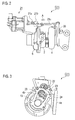
- Fig. 1 is a schematic cross-sectional view of a turbocharger.
- a direction of an arrow F indicates a front side of a turbocharger C while a direction of an arrow R indicates a rear side of the turbocharger C.
- the turbocharger C includes a turbocharger body 1.
- the turbocharger body 1 includes a bearing housing 2, a turbine housing 4 and a compressor housing 6.
- the turbine housing 4 is situated in front of the bearing housing 2, and is connected to the hearing housing 2 with bolts 3.
- the compressor housing 6 is situated in the rear of the bearing housing 2, and is connected to the bearing housing 2 with bolts 5.
- a bearing hole 2a is formed in the bearing housing 2.
- the bearing hole 2a penetrates the bearing housing 2 in a front-rear direction of the turbocharger C.
- a turbine shaft 7 is inserted in the bearing hole 2a, and is rotatably supported by the bearing hole 2a with bearings in between.
- a turbine impeller 8 is integrally linked (connected) to a front end portion (one end) of the turbine shaft 7.
- the turbine impeller 8 is rotatably housed in the turbine housing 4.
- a compressor impeller 9 is integrally linked (connected) to a rear end portion (the other end) of the turbine shaft 7.
- the compressor impeller 9 is rotatably housed in the compressor housing 6.
- the compressor housing 6 includes an inlet port 10, which is opened toward the rear of the turbocharger C and connected to a not-illustrated air cleaner.
- the inlet port 10 is opened toward the rear of the turbocharger C, and is connected to the air cleaner, which is not illustrated.
- the opposing surfaces of the two housings 2, 6 form a diffuser passage 11 configured to boost the pressure of the air by compressing the air.
- the diffuser passage 11 is formed into an annular shape from its inner to outer sides in radial directions of the turbine shaft 7 (the compressor impeller 9). The inner side of the diffuser passage 11 in the radial directions communicates with the inlet port 10 via the compressor impeller 9.
- the compressor housing 6 includes an annular compressor scroll passage 12.
- the compressor scroll passage 12 is situated outward of the diffuser passage 11 in the radial directions of the turbine shaft 7 (the compressor impeller 9), communicates with an intake port of an engine, and communicates with the diffuser passage 11 as well. For this reason, once the compressor impeller 9 rotates, a fluid is taken into the compressor housing 6 from the inlet port 10; the pressure of the fluid taken in is boosted by the diffuser passage 11 and the compressor scroll passage 12; and the resultant fluid is guided to the intake port of the engine.
- the turbine housing 4 includes a discharge port 13.
- the discharge port 13 is opened toward the front of the turbocharger C, and is connected to an exhaust emission controller, which is not illustrated. Furthermore, when the turbine housing 4 is connected to the bearing housing 2 with the bolts 3, the opposing surfaces of the two housings 2, 4 form a passage 14.
- the passage 14 is formed into an annular shape from its inner to outer sides in the radial directions of the turbine shaft 7 (the turbine impeller 8).
- the turbine housing 4 includes an annular turbine scroll passage 15.
- the turbine scroll passage 15 is situated outward of the passage 14 in the radial directions of the turbine shaft 7 (the turbine impeller 8), communicates with a gas inlet 4a (see Fig. 3 ) to which an exhaust gas emitted from an exhaust port of the engine is guided, and communicates with the passage 14 as well.
- the exhaust gas from the engine is guided from the gas inlet 4a to the turbine scroll passage 15, and is further guided to the discharge port 13 via the passage 14 and the turbine impeller 8.
- the exhaust gas rotates the turbine impeller 8.
- the torque of the turbine impeller 8 is transmitted to the compressor impeller 9 via the turbine shaft 7, and thereby, the compressor impeller 9 rotates.
- the torque of the compressor impeller 9 boosts the pressure of the fluid taken in, and the resultant fluid is guided to the intake port of the engine.
- Fig. 2 is a front view of the turbocharger C.
- Fig. 3 is a side view of the turbocharger C.
- the turbine housing 4 is provided with a bypass hole 4b.
- the bypass hole 4b penetrates the turbine housing 4 from a wall portion between the gas inlet 4a and the turbine scroll passage 15 toward the surface to which the discharge port 13 is opened. Part of the fluid to be guided to the turbine impeller 8 can bypass (flow to the downstream of) the turbine impeller 8 via the bypass hole 4b.
- a wastegate valve 20 functions as an on-off valve configured to close the bypass hole 4b by coming into contact with the bypass hole 4b, and to open the bypass hole 4b by becoming separated from the bypass hole 4b. In other words, the wastegate valve 20 makes part of the fluid to be guided to the turbine impeller 8 flow to the downstream of the turbine impeller 8 while bypassing the turbine impeller 8.
- the wastegate valve 20 is connected to an electrically-operated actuator 21.
- the electrically-operated actuator 21 includes: an actuation unit 21a made from a motor or the like; and a rod 21c connected to the actuation unit 21a.
- a heat shield plate 21b is attached to the actuation unit 21a. The heat shield plate 21b blocks radiant heat from heat sources such as the engine. As shown in Fig. 2 , the rod 21c moves in a direction indicated with an arrow A in response to the actuation by the actuation unit 21a.
- One end of a connecting member 22 is turnably supported by the extremity of the rod 21c, while the other end of the connecting member 22 is fixed to one end of a turnably-supported shaft 23.
- the other end of the shaft 23 is connected to the wastegate valve 20 by use of an attachment plate 24. For this reason, once the rod 21c moves in the direction indicated with the arrow A, the connecting member 22 turns around its end portion fixed to the shaft 23.
- the turn of the connecting member 22 makes the shaft 23 turn in a direction indicated with an arrow B in Fig. 3 .
- the valve lift of the wastegate valve 20 is adjusted in accordance with how much the shaft 23 turns.
- the electrically-operated actuator 21 adjusts the amount of the fluid (exhaust gas) to bypass the turbine impeller 8 by operating the connecting member 22, suppresses the pressure of the exhaust gas flowing into the turbine scroll passage 15 from the gas inlet 4a, and adjusts rotation output from the turbine impeller 8.
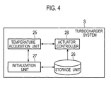
- Fig. 4 is a block diagram for explaining how the electrically-operated actuator 21 is controlled in a turbocharger system S.
- the turbocharger system S is formed from the above-described turbocharger C, and an engine control unit (ECU) for the engine connected to the turbocharger C.
- Fig. 4 shows a functioning section in the ECU which constitutes the turbocharger system S, the functioning section being involved in controlling the actuator 21. Descriptions for other functioning sections of the ECU will be omitted.
- the functioning section involved in controlling the electrically-operated actuator 21 does not always have to be incorporated in the ECU. Instead, the functioning section may be incorporated in a different control unit.
- a temperature acquisition unit 25 shown in Fig. 4 acquires a target temperature by use of a temperature sensor, albeit not illustrated, in accordance with control by one of an initialization unit 27 and an actuator controller 28, which will be described later.
- the target temperature is that which correlates with the temperature of the turbocharger body 1.
- the target temperature include: a measured value of the temperature of the external wall of the turbine housing 4; and a measured value of the temperature of the surface of the rod 21c of the electrically-operated actuator 21.
- the target temperature may be a measured value of the temperature of the exhaust gas flowing into the turbine housing 4, or a measured value of the temperature of a catalyst (the exhaust emission controller) connected to the turbocharger C and provided in an exhaust gas passage of the engine.
- the temperature acquisition unit 25 may acquire the temperature from the temperature sensor at all times, or only when an instruction to measure the temperature comes from the initialization unit 27 or the actuator controller 28.
- a storage unit 26 is formed from a storage medium such as a flash memory.
- the storage unit 26 stores a reference value associated with a reference temperature (normal temperature in the embodiment) in accordance with control from the initialization unit 27.
- the reference value is a control value (voltage) to be inputted into the electrically-operated actuator 21 when the wastegate valve 20 becomes fully closed at the reference temperature.
- the storage unit 26 stores association information in which correction values at target temperatures are associated with the target temperatures.
- Each correction value is a difference value between the reference value and the control value to be inputted into the electrically-operated actuator 21 when the wastegate valve 20 becomes fully closed at the target temperature.
- the storage unit 26 stores as the association information a table in which the target temperatures and the correction values are associated with one another.
- the reference value is determined as follows. First of all, the initialization unit 27 makes the temperature acquisition unit 25 acquire the target temperature in accordance with the user's input manipulation, for example. Subsequently, the initialization unit 27 sets the acquired target temperature as the reference temperature, and outputs a provisional control value corresponding to the temperature to the electrically-operated actuator 21. In this respect, the user fine-tunes the control value by performing the input manipulation on the initialization unit 27 in order to make the wastegate valve 20 become closed just fully. Instead, however, an operation program or the like may perform the input manipulation on the initialization unit 27. Thereafter, the initialization unit 27 makes the storage unit 26 store as the reference value a control value inputted when this tuning makes the wastegate vale 20 become fully closed.
- the wastegate valve 20 When the wastegate valve 20 comes into contact with and hits the bypass hole 4b in conjunction with the movement of the rod 21c of the electrically-operated actuator 21, the wastegate valve 20 becomes fully closed.
- the position of the rod 21c when the wastegate valve 20 becomes fully closed is checked, for example, by a position sensor, a load sensor or the like which is provided inside or outside the electrically-operated actuator.
- the hot period means a state where (a period of time in which) the turbocharger C is exposed to a temperature accompanying thermal expansion or thermal contraction.
- An example of the hot period is a state where the engine to which the turbocharger C is connected is in operation. In this case, the exhaust gas at a high temperature corresponding to the operating condition is guided to the turbocharger C, and the turbocharger C is accordingly heated.
- the initialization unit 27 makes the temperature acquisition unit 25 acquire the target temperature, for example in accordance with the user's input manipulation. Thereafter, the temperature acquisition unit 25 outputs the control value based on the acquired target temperature to the electrically-operated actuator 21.
- the user, the operation program or the like fine-tunes the control value by performing the input manipulation on the initialization unit 27 in order to make the wastegate valve 20 become closed just fully. Subsequently, the initialization unit 27 calculates a difference value between the reference value and the control value inputted when the tuning makes the wastegate valve 20 become fully closed. Furthermore, the initialization unit 27 sets the calculated difference value as the correction value, associates this correction value with the target temperature, and makes the storage unit 26 store the associated combination as the association information.
- the actuator controller 28 controls the electrically-operated actuator 21 on the basis of the target temperature acquired by the temperature acquisition unit 25. To put it in detail, the actuator controller 28 identifies the correction value on the basis of: the target temperature acquired by the temperature acquisition unit 25; and the association information stored in the storage unit 26. Subsequently, the actuator controller 28 calculates a control value (voltage) by adding or subtracting the identified correction value to or from the control value inputted into the electrically-operated actuator 21. On the basis of the calculated control value, the actuator controller 28 controls the electrically-operated actuator 21.
- the control value inputted into the electrically-operated actuator 21 is calculated on the basis of the valve lift of the wastegate valve 20.
- the valve lift of the wastegate valve 20 is determined by the ECU with the number of revolutions of the engine, the engine intake and displacement, and the like taken into consideration.
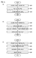
- Fig. 5 depicts flowcharts for explaining a method of controlling the turbocharger system S.
- Fig. 5(a) shows a flow of a process of setting the turbocharger system S during the normal-temperature period
- Fig. 5(b) shows a flow of a process of setting the turbocharger system S during the hot period
- Fig. 5(c) shows a flow of a process of setting the turbocharger system S during operation.
- the initialization unit 27 acquires the target temperature from the temperature acquisition unit 25, and sets the acquired target temperature as the reference temperature (S200). Thereafter, the initialization unit 27 makes the wastegate valve 20 become fully closed, for example in accordance with the user's input manipulation, the operation program's input process, and the like (S202). After that, the initialization unit 27 makes the storage unit 26 store as the reference value the control value (voltage) which is inputted into the electrically-operated actuator 21 when the wastegate valve 20 becomes fully closed (S204).
- the initialization unit 27 acquires the target temperature from the acquisition unit 25 (S220).
- the initialization unit 27 makes the wastegate valve 20 become fully closed, for example in accordance with the user's input manipulation, the operation program's input process, and the like (S222).
- the initialization unit 27 subtracts the control value inputted at this time into the electrically-operated actuator 21 from the reference value stored in the storage unit 26 (S224), and makes the storage unit 26 store the obtained difference as the correction value in association with the target temperature (S226).
- Such a process shown in Fig. 5 (b) is performed under each of multiple operating conditions, i.e., for each of multiple different target temperatures.
- the actuator controller 28 acquires the target temperature T from the temperature acquisition unit 25 (S240).
- the actuator controller 28 refers to the table which is the association information stored in the storage unit 26. In the table, for example, the correction values are associated with predetermined target temperature ranges, respectively.
- the actuator controller 28 acquires the correction value associated with the target temperature T acquired from the temperature acquisition unit 25 (S242).
- the actuator controller 28 calculates an appropriate control value for the target temperature T by adding the acquired correction value to the reference value stored in the storage unit 26 (S244). Furthermore, the actuator controller 28 controls the electrically-operated actuator 21 on the basis of the calculated control value, and thereby adjusts the valve lift of the wastegate valve 20 (S246).
- the actuator controller 28 controls the electrically-operated actuator 21 depending on the target temperature.
- the turbocharger system S is capable of appropriately adjusting the valve lift of the wastegate valve 20, even if depending on the use conditions, changes in the temperature of the turbocharger body 1 thermally expand the turbocharger body 1 and the electrically-operated actuator 21, hence resulting in changes in the relative positions of the wastegate valve 20 and the bypass hole 4b to be closed by the wastegate valve 20.
- the storage unit 26 may store, as the association information, an arithmetic expression enabling the correction value to be calculated from the target temperature.
- Fig. 6 is a graph showing an example of a relationship between the target temperature and the correction value. Descriptions will be provided for the graph citing the example where: the control value inputted into the electrically-operated actuator 21 at normal temperature T0 is set as the reference value; and the target temperature and the correction value corresponding to the reference value are in proportion to each other.
- the initialization unit 27 After performing the process shown in Fig. 5(b) under the multiple operating conditions, the initialization unit 27 derives the arithmetic expression (a proportional expression in this case), which enables the correction value to be approximately calculated from the target temperature, on the basis of the target temperature and the correction value stored in the storage unit 26. Then, the initialization unit 27 makes the storage unit 26 store the arithmetic expression.
- the arithmetic expression a proportional expression in this case
- the actuator controller 28 becomes capable of identifying the correction value for a target temperature T1 as a correction value ⁇ a, and the correction value for a target temperature T2 as a correction value ⁇ b, as shown in Fig. 6 .
- the turbocharger system S When the arithmetic expression is used as the association information, the turbocharger system S only needs to store the arithmetic expression in the storage unit 26 instead of storing the table therein. Accordingly, the storage capacity needed for the storage unit 26 can be reduced.
- the turbocharger system S is capable of identifying a single correction value uniquely for one target temperature unlike when the turbocharger system S identifies the correction value on the basis of the table, and accordingly can achieve more delicate control.
- the turbocharger system S need not perform the arithmetic process for calculating the control value from the target temperature, and is capable of acquiring the correction value by just referring to the table. For this reason, the turbocharger system S is capable of reducing the process load unlike when the arithmetic expression is used as the association information. Furthermore, even if the relationship between the target temperature and the control value is too complicate to be expressed with the arithmetic expression, the turbocharger system S is capable of dealing with the relationship by storing the target information in the storage unit 26 in the form of a simple table.
- the configuration of the initialization unit 27 is not limited to that in which: the normal temperature T0 is used as the reference temperature; and the control value which makes the wastegate valve 20 become fully closed at the normal temperature T0 is used as the reference value.
- the configuration of the initialization unit 27 may be that in which: a target temperature while the engine is in operation, for example a target temperature T1, is used as the reference temperature; and a control value which makes the wastegate valve 20 become fully closed at the target temperature T1 is used as the reference value.
- a control value corresponding to the highest possible temperature may be used as the upper limit value on the control value which makes the wastegate valve 20 become fully closed.
- the thermal expansion makes the relative position of the wastegate valve 20 closer to the bypass hole 4b.
- the control value corresponding to the highest possible temperature under the operating conditions is set as the upper limit value, it is possible to inhibit an excessive load from being applied to the wastegate valve 20, the rod 21c of the electrically-operated actuator 21, and the like while the wastegate valve 20 is fully closed.
- control values and the correction values are expressed in the form of voltages
- the control values and the correction values may be expressed in the form of currents instead.
- the control values and the correction values may be expressed in the form of analog signals or digital signals.
- the present invention can be used for: the turbocharger system which adjusts the flow rate of the fluid to be guided to the downstream of the turbine impeller by making part of the fluid bypass the turbine impeller; and the control method for the turbocharger system.
Landscapes
- Engineering & Computer Science (AREA)
- Chemical & Material Sciences (AREA)
- Combustion & Propulsion (AREA)
- Mechanical Engineering (AREA)
- General Engineering & Computer Science (AREA)
- Supercharger (AREA)
Description
- The present invention relates to a turbocharger system and a control method for the same.
- Turbochargers have been known as being used to increase output of engines and the like by being connected thereto. As boost pressure of a turbocharger becomes higher, the subsequent flow rate and pressure of the exhaust gas become higher. As the torque of the turbocharger becomes higher, the boost pressure becomes much higher. As a result, the engine and the turbocharger become more likely to suffer damage. To avoid this, some turbocharges have a function of suppressing the pressure of the exhaust gas flowing into a turbine housing by making part of the exhaust gas flow from the engine to the downstream of the turbine while bypassing the turbine.
- A turbocharger having the foregoing function is provided with a bypass passage making the upstream and downstream of a turbine impeller communicate with each other. The turbocharger is further provided with a wastegate valve configured to open and close the bypass passage. Depending on the pressure in a compressor housing, the valve lift (a degree of opening) of the wastegate valve is adjusted by an actuator connected to the wastegate valve.
- As the shape of the turbocharger changes with time, the relative positions of the wastegate valve and a hole to be closed by the wastegate valve also change. For this reason, the actuator, if electrically operated, becomes no longer capable of adjusting the opening of the hole appropriately even when controlling the wastegate valve.
PTL 1 has proposed a turbocharger having a function of resetting the relationship between the control amount and the valve lift of the wastegate valve when necessary. - [PTL 1] Japanese Patent No.
4434057 - The temperature of the turbocharger drastically changes depending on a use condition including, for example, output from the engine connected to the turbocharger. The thermal expansion associated with such a change in the temperature changes the overall shape of the turbocharger, and also changes the relative positions of the wastegate valve and the hole to be closed by the wastegate valve. For this reason, despite the use of the turbocharger described in
PTL 1 with the wastegate valve controlled by the electrically-operated actuator, there is still a problem, due to temperature variations depending on use conditions, that the valve lift cannot be adjusted appropriately, i.e., that a leak may occur or the wastegate valve may apply too large tightening force to close the hole. - An object of the present invention is to provide a turbocharger system and a control method for the same, which are capable of appropriately adjusting the valve lift of the wastegate valve irrespective of the temperature of the turbocharger.
- A first aspect of the present invention provides a turbocharger system which includes: a turbocharger body including a compressor housing and a turbine housing; a turbine shaft rotatably supported by the turbocharger body, and linking a turbine impeller in the turbine housing and a compressor impeller in the compressor housing; a wastegate valve configured to make part of a fluid to be guided to the turbine impeller flow to a downstream of the turbine impeller while bypassing the turbine impeller; an electrically-operated actuator connected to the wastegate valve, and configured to adjust a valve lift of the wastegate valve; a temperature acquisition unit configured to acquire a target temperature which is any one of a temperature of the turbocharger body and a temperature correlating with the temperature of the turbocharger body; and an actuator controller configured to control the electrically-operated actuator on the basis of the target temperature.
- The turbocharger system may further include a storage unit configured to store association information which associates a correction value with the target temperature. In this case, the correction value is a difference value between a control value inputted into the electrically-operated actuator when the wastegate valve becomes fully closed at the target temperature associated with the correction value, and a reference value which is a control value inputted into the electrically-operated actuator when the wastegate valve becomes fully closed at a reference temperature. On the basis of the association information, the actuator controller may identify the correction value from the target temperature acquired by the temperature acquisition unit, calculate a control value by adding or subtracting the identified correction value to or from an input value for control of the electrically-operated actuator, and control the electrically-operated actuator on the basis of the calculated control value.
- The storage unit may store as the association information a table in which the target temperature and the correction value are associated with each other.
- The storage unit may store as the association information an arithmetic expression enabling the correction value to be calculated from the target temperature.
- A second aspect of the present invention provides a turbocharger system controlling method for a turbocharger system, which includes an electrically-operated actuator configured to adjust a valve lift of a wastegate valve for making part of a fluid to be guided to a turbine impeller flow to a downstream of the turbine impeller while bypassing the turbine impeller. The controlling method includes: acquiring a target temperature which is any one of a temperature of a turbocharger body and a temperature correlating with the temperature of the turbocharger body; and controlling the electrically-operated actuator on the basis of the target temperature.
- The present invention makes it possible to appropriately adjust the valve lift of the wastegate valve irrespective of the temperature of the turbocharger.
-
- [
Fig. 1 ]
Fig. 1 is a schematic cross-sectional view of a turbocharger. - [
Fig. 2 ]
Fig. 2 is a front view of the turbocharger. - [
Fig. 3 ]
Fig. 3 is a side view of the turbocharger. - [
Fig. 4 ]
Fig. 4 is a block diagram for explaining how an electrically-operated actuator is controlled. - [
Fig. 5 ]
Fig. 5 depicts flowcharts for explaining a method of controlling a turbocharger system. - [
Fig. 6 ]
Fig. 6 is a graph showing an example of a relationship between a target temperature and a correction value. - Referring to the accompanying drawings, descriptions will be provided for an embodiment of the present invention. Dimensions, materials, specific values and the like shown in the embodiment are provided as mere examples for the purpose of making the present invention easily understood, and do not limit the present invention unless otherwise indicated. Incidentally, in the description and drawings, components having virtually the same functions and configurations will be denoted by the same reference signs, and thereby, duplicated descriptions will be omitted. Furthermore, illustration of components not directly related to the present invention will be omitted.
-
Fig. 1 is a schematic cross-sectional view of a turbocharger. In the following description, a direction of an arrow F indicates a front side of a turbocharger C while a direction of an arrow R indicates a rear side of the turbocharger C. As shown inFig. 1 , the turbocharger C includes aturbocharger body 1. Theturbocharger body 1 includes a bearing housing 2, aturbine housing 4 and acompressor housing 6. Theturbine housing 4 is situated in front of the bearing housing 2, and is connected to the hearing housing 2 with bolts 3. Thecompressor housing 6 is situated in the rear of the bearing housing 2, and is connected to the bearing housing 2 withbolts 5. - A
bearing hole 2a is formed in the bearing housing 2. Thebearing hole 2a penetrates the bearing housing 2 in a front-rear direction of the turbocharger C. A turbine shaft 7 is inserted in thebearing hole 2a, and is rotatably supported by thebearing hole 2a with bearings in between. Aturbine impeller 8 is integrally linked (connected) to a front end portion (one end) of the turbine shaft 7. Theturbine impeller 8 is rotatably housed in theturbine housing 4. In addition, a compressor impeller 9 is integrally linked (connected) to a rear end portion (the other end) of the turbine shaft 7. The compressor impeller 9 is rotatably housed in thecompressor housing 6. - The
compressor housing 6 includes aninlet port 10, which is opened toward the rear of the turbocharger C and connected to a not-illustrated air cleaner. Theinlet port 10 is opened toward the rear of the turbocharger C, and is connected to the air cleaner, which is not illustrated. Furthermore, when thecompressor housing 6 is connected to the bearing housing 2 with thebolts 5, the opposing surfaces of the twohousings 2, 6 form adiffuser passage 11 configured to boost the pressure of the air by compressing the air. Thediffuser passage 11 is formed into an annular shape from its inner to outer sides in radial directions of the turbine shaft 7 (the compressor impeller 9). The inner side of thediffuser passage 11 in the radial directions communicates with theinlet port 10 via the compressor impeller 9. - The
compressor housing 6 includes an annularcompressor scroll passage 12. Thecompressor scroll passage 12 is situated outward of thediffuser passage 11 in the radial directions of the turbine shaft 7 (the compressor impeller 9), communicates with an intake port of an engine, and communicates with thediffuser passage 11 as well. For this reason, once the compressor impeller 9 rotates, a fluid is taken into thecompressor housing 6 from theinlet port 10; the pressure of the fluid taken in is boosted by thediffuser passage 11 and thecompressor scroll passage 12; and the resultant fluid is guided to the intake port of the engine. - The
turbine housing 4 includes adischarge port 13. Thedischarge port 13 is opened toward the front of the turbocharger C, and is connected to an exhaust emission controller, which is not illustrated. Furthermore, when theturbine housing 4 is connected to the bearing housing 2 with the bolts 3, the opposing surfaces of the twohousings 2, 4 form apassage 14. Thepassage 14 is formed into an annular shape from its inner to outer sides in the radial directions of the turbine shaft 7 (the turbine impeller 8). - The
turbine housing 4 includes an annularturbine scroll passage 15. Theturbine scroll passage 15 is situated outward of thepassage 14 in the radial directions of the turbine shaft 7 (the turbine impeller 8), communicates with agas inlet 4a (seeFig. 3 ) to which an exhaust gas emitted from an exhaust port of the engine is guided, and communicates with thepassage 14 as well. For this reason, the exhaust gas from the engine is guided from thegas inlet 4a to theturbine scroll passage 15, and is further guided to thedischarge port 13 via thepassage 14 and theturbine impeller 8. During its flowing process, the exhaust gas rotates theturbine impeller 8. The torque of theturbine impeller 8 is transmitted to the compressor impeller 9 via the turbine shaft 7, and thereby, the compressor impeller 9 rotates. The torque of the compressor impeller 9 boosts the pressure of the fluid taken in, and the resultant fluid is guided to the intake port of the engine. -
Fig. 2 is a front view of the turbocharger C.Fig. 3 is a side view of the turbocharger C. As shown inFig. 3 , theturbine housing 4 is provided with abypass hole 4b. Thebypass hole 4b penetrates theturbine housing 4 from a wall portion between thegas inlet 4a and theturbine scroll passage 15 toward the surface to which thedischarge port 13 is opened. Part of the fluid to be guided to theturbine impeller 8 can bypass (flow to the downstream of) theturbine impeller 8 via thebypass hole 4b. Awastegate valve 20 functions as an on-off valve configured to close thebypass hole 4b by coming into contact with thebypass hole 4b, and to open thebypass hole 4b by becoming separated from thebypass hole 4b. In other words, thewastegate valve 20 makes part of the fluid to be guided to theturbine impeller 8 flow to the downstream of theturbine impeller 8 while bypassing theturbine impeller 8. - The
wastegate valve 20 is connected to an electrically-operatedactuator 21. The electrically-operatedactuator 21 includes: anactuation unit 21a made from a motor or the like; and arod 21c connected to theactuation unit 21a. Aheat shield plate 21b is attached to theactuation unit 21a. Theheat shield plate 21b blocks radiant heat from heat sources such as the engine. As shown inFig. 2 , therod 21c moves in a direction indicated with an arrow A in response to the actuation by theactuation unit 21a. - One end of a connecting
member 22 is turnably supported by the extremity of therod 21c, while the other end of the connectingmember 22 is fixed to one end of a turnably-supportedshaft 23. The other end of theshaft 23 is connected to thewastegate valve 20 by use of anattachment plate 24. For this reason, once therod 21c moves in the direction indicated with the arrow A, the connectingmember 22 turns around its end portion fixed to theshaft 23. The turn of the connectingmember 22 makes theshaft 23 turn in a direction indicated with an arrow B inFig. 3 . The valve lift of thewastegate valve 20 is adjusted in accordance with how much theshaft 23 turns. - Thereby, the electrically-operated
actuator 21 adjusts the amount of the fluid (exhaust gas) to bypass theturbine impeller 8 by operating the connectingmember 22, suppresses the pressure of the exhaust gas flowing into theturbine scroll passage 15 from thegas inlet 4a, and adjusts rotation output from theturbine impeller 8. -
Fig. 4 is a block diagram for explaining how the electrically-operatedactuator 21 is controlled in a turbocharger system S. The turbocharger system S is formed from the above-described turbocharger C, and an engine control unit (ECU) for the engine connected to the turbocharger C.Fig. 4 shows a functioning section in the ECU which constitutes the turbocharger system S, the functioning section being involved in controlling theactuator 21. Descriptions for other functioning sections of the ECU will be omitted. Here, the functioning section involved in controlling the electrically-operatedactuator 21 does not always have to be incorporated in the ECU. Instead, the functioning section may be incorporated in a different control unit. - A
temperature acquisition unit 25 shown inFig. 4 acquires a target temperature by use of a temperature sensor, albeit not illustrated, in accordance with control by one of aninitialization unit 27 and anactuator controller 28, which will be described later. - The target temperature is that which correlates with the temperature of the
turbocharger body 1. Examples of the target temperature include: a measured value of the temperature of the external wall of theturbine housing 4; and a measured value of the temperature of the surface of therod 21c of the electrically-operatedactuator 21. Otherwise, the target temperature may be a measured value of the temperature of the exhaust gas flowing into theturbine housing 4, or a measured value of the temperature of a catalyst (the exhaust emission controller) connected to the turbocharger C and provided in an exhaust gas passage of the engine. In addition, thetemperature acquisition unit 25 may acquire the temperature from the temperature sensor at all times, or only when an instruction to measure the temperature comes from theinitialization unit 27 or theactuator controller 28. - A
storage unit 26 is formed from a storage medium such as a flash memory. Thestorage unit 26 stores a reference value associated with a reference temperature (normal temperature in the embodiment) in accordance with control from theinitialization unit 27. In this respect, the reference value is a control value (voltage) to be inputted into the electrically-operatedactuator 21 when thewastegate valve 20 becomes fully closed at the reference temperature. - In accordance with the control from the
initialization unit 27, thestorage unit 26 stores association information in which correction values at target temperatures are associated with the target temperatures. Each correction value is a difference value between the reference value and the control value to be inputted into the electrically-operatedactuator 21 when thewastegate valve 20 becomes fully closed at the target temperature. In this respect, thestorage unit 26 stores as the association information a table in which the target temperatures and the correction values are associated with one another. - In a process of setting the turbocharger system S during a normal-temperature period, the reference value is determined as follows. First of all, the
initialization unit 27 makes thetemperature acquisition unit 25 acquire the target temperature in accordance with the user's input manipulation, for example. Subsequently, theinitialization unit 27 sets the acquired target temperature as the reference temperature, and outputs a provisional control value corresponding to the temperature to the electrically-operatedactuator 21. In this respect, the user fine-tunes the control value by performing the input manipulation on theinitialization unit 27 in order to make thewastegate valve 20 become closed just fully. Instead, however, an operation program or the like may perform the input manipulation on theinitialization unit 27. Thereafter, theinitialization unit 27 makes thestorage unit 26 store as the reference value a control value inputted when this tuning makes thewastegate vale 20 become fully closed. - When the
wastegate valve 20 comes into contact with and hits thebypass hole 4b in conjunction with the movement of therod 21c of the electrically-operatedactuator 21, thewastegate valve 20 becomes fully closed. The position of therod 21c when thewastegate valve 20 becomes fully closed is checked, for example, by a position sensor, a load sensor or the like which is provided inside or outside the electrically-operated actuator. - In a process of setting the turbocharger system S during a hot period, the correction value is determined as follows. In this respect, the hot period means a state where (a period of time in which) the turbocharger C is exposed to a temperature accompanying thermal expansion or thermal contraction. An example of the hot period is a state where the engine to which the turbocharger C is connected is in operation. In this case, the exhaust gas at a high temperature corresponding to the operating condition is guided to the turbocharger C, and the turbocharger C is accordingly heated. First of all, the
initialization unit 27 makes thetemperature acquisition unit 25 acquire the target temperature, for example in accordance with the user's input manipulation. Thereafter, thetemperature acquisition unit 25 outputs the control value based on the acquired target temperature to the electrically-operatedactuator 21. The user, the operation program or the like fine-tunes the control value by performing the input manipulation on theinitialization unit 27 in order to make thewastegate valve 20 become closed just fully. Subsequently, theinitialization unit 27 calculates a difference value between the reference value and the control value inputted when the tuning makes thewastegate valve 20 become fully closed. Furthermore, theinitialization unit 27 sets the calculated difference value as the correction value, associates this correction value with the target temperature, and makes thestorage unit 26 store the associated combination as the association information. - While the engine connected to the turbocharger C is in operation, the
actuator controller 28 controls the electrically-operatedactuator 21 on the basis of the target temperature acquired by thetemperature acquisition unit 25. To put it in detail, theactuator controller 28 identifies the correction value on the basis of: the target temperature acquired by thetemperature acquisition unit 25; and the association information stored in thestorage unit 26. Subsequently, theactuator controller 28 calculates a control value (voltage) by adding or subtracting the identified correction value to or from the control value inputted into the electrically-operatedactuator 21. On the basis of the calculated control value, theactuator controller 28 controls the electrically-operatedactuator 21. - The control value inputted into the electrically-operated
actuator 21 is calculated on the basis of the valve lift of thewastegate valve 20. The valve lift of thewastegate valve 20 is determined by the ECU with the number of revolutions of the engine, the engine intake and displacement, and the like taken into consideration. -
Fig. 5 depicts flowcharts for explaining a method of controlling the turbocharger system S. In particular,Fig. 5(a) shows a flow of a process of setting the turbocharger system S during the normal-temperature period;Fig. 5(b) shows a flow of a process of setting the turbocharger system S during the hot period; andFig. 5(c) shows a flow of a process of setting the turbocharger system S during operation. - First of all, during the normal-temperature period, as shown in
Fig. 5(a) , theinitialization unit 27 acquires the target temperature from thetemperature acquisition unit 25, and sets the acquired target temperature as the reference temperature (S200). Thereafter, theinitialization unit 27 makes thewastegate valve 20 become fully closed, for example in accordance with the user's input manipulation, the operation program's input process, and the like (S202). After that, theinitialization unit 27 makes thestorage unit 26 store as the reference value the control value (voltage) which is inputted into the electrically-operatedactuator 21 when thewastegate valve 20 becomes fully closed (S204). - Subsequently, during the hot period, as shown in
Fig. 5(b) , theinitialization unit 27 acquires the target temperature from the acquisition unit 25 (S220). - Like in step S202, the
initialization unit 27 makes thewastegate valve 20 become fully closed, for example in accordance with the user's input manipulation, the operation program's input process, and the like (S222). Theinitialization unit 27 subtracts the control value inputted at this time into the electrically-operatedactuator 21 from the reference value stored in the storage unit 26 (S224), and makes thestorage unit 26 store the obtained difference as the correction value in association with the target temperature (S226). - Such a process shown in
Fig. 5 (b) is performed under each of multiple operating conditions, i.e., for each of multiple different target temperatures. - As shown in
Fig. 5 (c) , in a case where the opening of thebypass hole 4b is adjusted while the turbocharger C is in operation, theactuator controller 28 acquires the target temperature T from the temperature acquisition unit 25 (S240). Theactuator controller 28 refers to the table which is the association information stored in thestorage unit 26. In the table, for example, the correction values are associated with predetermined target temperature ranges, respectively. Theactuator controller 28 acquires the correction value associated with the target temperature T acquired from the temperature acquisition unit 25 (S242). - The
actuator controller 28 calculates an appropriate control value for the target temperature T by adding the acquired correction value to the reference value stored in the storage unit 26 (S244). Furthermore, theactuator controller 28 controls the electrically-operatedactuator 21 on the basis of the calculated control value, and thereby adjusts the valve lift of the wastegate valve 20 (S246). - As described above, in the turbocharger system S of the embodiment, the
actuator controller 28 controls the electrically-operatedactuator 21 depending on the target temperature. For this reason, the turbocharger system S is capable of appropriately adjusting the valve lift of thewastegate valve 20, even if depending on the use conditions, changes in the temperature of theturbocharger body 1 thermally expand theturbocharger body 1 and the electrically-operatedactuator 21, hence resulting in changes in the relative positions of thewastegate valve 20 and thebypass hole 4b to be closed by thewastegate valve 20. - The
storage unit 26 may store, as the association information, an arithmetic expression enabling the correction value to be calculated from the target temperature. -
Fig. 6 is a graph showing an example of a relationship between the target temperature and the correction value. Descriptions will be provided for the graph citing the example where: the control value inputted into the electrically-operatedactuator 21 at normal temperature T0 is set as the reference value; and the target temperature and the correction value corresponding to the reference value are in proportion to each other. - After performing the process shown in
Fig. 5(b) under the multiple operating conditions, theinitialization unit 27 derives the arithmetic expression (a proportional expression in this case), which enables the correction value to be approximately calculated from the target temperature, on the basis of the target temperature and the correction value stored in thestorage unit 26. Then, theinitialization unit 27 makes thestorage unit 26 store the arithmetic expression. - Thereby, using the arithmetic expression, the
actuator controller 28 becomes capable of identifying the correction value for a target temperature T1 as a correction value Δa, and the correction value for a target temperature T2 as a correction value Δb, as shown inFig. 6 . - When the arithmetic expression is used as the association information, the turbocharger system S only needs to store the arithmetic expression in the
storage unit 26 instead of storing the table therein. Accordingly, the storage capacity needed for thestorage unit 26 can be reduced. In addition, the turbocharger system S is capable of identifying a single correction value uniquely for one target temperature unlike when the turbocharger system S identifies the correction value on the basis of the table, and accordingly can achieve more delicate control. - On the other hand, when the table is used as the association information as described above, the turbocharger system S need not perform the arithmetic process for calculating the control value from the target temperature, and is capable of acquiring the correction value by just referring to the table. For this reason, the turbocharger system S is capable of reducing the process load unlike when the arithmetic expression is used as the association information. Furthermore, even if the relationship between the target temperature and the control value is too complicate to be expressed with the arithmetic expression, the turbocharger system S is capable of dealing with the relationship by storing the target information in the
storage unit 26 in the form of a simple table. - For this reason, it is desirable to determine whether the table or the arithmetic expression should be stored as the association information, depending on the capacity of the
storage unit 26, the processing capabilities of theinitialization unit 27 and theactuator controller 28, and the like. - Moreover, the configuration of the
initialization unit 27 is not limited to that in which: the normal temperature T0 is used as the reference temperature; and the control value which makes thewastegate valve 20 become fully closed at the normal temperature T0 is used as the reference value. Instead, the configuration of theinitialization unit 27 may be that in which: a target temperature while the engine is in operation, for example a target temperature T1, is used as the reference temperature; and a control value which makes thewastegate valve 20 become fully closed at the target temperature T1 is used as the reference value. Furthermore, if the highest possible temperature under the operating conditions is used as the target temperature T1, a control value corresponding to the highest possible temperature may be used as the upper limit value on the control value which makes thewastegate valve 20 become fully closed. As the target temperature becomes higher, the thermal expansion makes the relative position of thewastegate valve 20 closer to thebypass hole 4b. When the control value corresponding to the highest possible temperature under the operating conditions is set as the upper limit value, it is possible to inhibit an excessive load from being applied to thewastegate valve 20, therod 21c of the electrically-operatedactuator 21, and the like while thewastegate valve 20 is fully closed. - Although in the foregoing embodiment, the control values and the correction values are expressed in the form of voltages, the control values and the correction values may be expressed in the form of currents instead. In addition, the control values and the correction values may be expressed in the form of analog signals or digital signals.
- The foregoing descriptions have been provided for the preferable embodiment of the present invention. However, it goes without saying that the present invention is not limited to such an embodiment. It is obvious to those skilled in the art that various modifications and corrections are possible within the scope as defined in the appended claims, and that such modifications and corrections are naturally encompassed by the technical scope of the present invention as well.
- The present invention can be used for: the turbocharger system which adjusts the flow rate of the fluid to be guided to the downstream of the turbine impeller by making part of the fluid bypass the turbine impeller; and the control method for the turbocharger system.
Claims (5)
- A turbocharger system comprising:a turbocharger body including a compressor housing and a turbine housing;a turbine shaft rotatably supported by the turbocharger body, and linking a turbine impeller in the turbine housing and a compressor impeller in the compressor housing;a wastegate valve configured to make part of a fluid to be guided to the turbine impeller flow to a downstream of the turbine impeller while bypassing the turbine impeller;an electrically-operated actuator connected to the wastegate valve, and configured to adjust a valve lift of the wastegate valve;a temperature acquisition unit configured to acquire a target temperature which is any one of a temperature of the turbocharger body and a temperature correlating with the temperature of the turbocharger body; andan actuator controller configured to control the electrically-operated actuator on the basis of the target temperature.
- The turbocharger system according to claim 1, further comprising a storage unit configured to store association information which associates a correction value with the target temperature, wherein
the correction value is a difference value between a control value inputted into the electrically-operated actuator when the wastegate valve becomes fully closed at the target temperature associated with the correction value, and a reference value which is a control value inputted into the electrically-operated actuator when the wastegate valve becomes fully closed at a reference temperature,
on the basis of the association information, the actuator controller identifies the correction value from the target temperature acquired by the temperature acquisition unit, and
the actuator controller calculates a control value by adding or subtracting the identified correction value to or from an input value for control of the electrically-operated actuator, and controls the electrically-operated actuator on the basis of the calculated control value. - The turbocharger system according to claim 2, wherein the storage unit stores as the association information a table in which the target temperature and the correction value are associated with each other.
- The turbocharger system according to claim 2, wherein the storage unit stores as the association information an arithmetic expression enabling the correction value to be calculated from the target temperature.
- A turbocharger system controlling method for a turbocharger system which includes an electrically-operated actuator configured to adjust a valve lift of a wastegate valve for making part of a fluid to be guided to a turbine impeller flow to a downstream of the turbine impeller while bypassing the turbine impeller, comprising:acquiring a target temperature which is any one of a temperature of a turbocharger body and a temperature correlating with the temperature of the turbocharger body; andcontrolling the electrically-operated actuator on the basis of the target temperature.
Applications Claiming Priority (2)
| Application Number | Priority Date | Filing Date | Title |
|---|---|---|---|
| JP2012004473A JP6155542B2 (en) | 2012-01-12 | 2012-01-12 | Supercharging system and control method of supercharging system |
| PCT/JP2013/050274 WO2013105592A1 (en) | 2012-01-12 | 2013-01-10 | Supercharging system and method for controlling supercharging system |
Publications (3)
| Publication Number | Publication Date |
|---|---|
| EP2803837A1 true EP2803837A1 (en) | 2014-11-19 |
| EP2803837A4 EP2803837A4 (en) | 2015-08-19 |
| EP2803837B1 EP2803837B1 (en) | 2018-05-16 |
Family
ID=48781536
Family Applications (1)
| Application Number | Title | Priority Date | Filing Date |
|---|---|---|---|
| EP13735573.1A Not-in-force EP2803837B1 (en) | 2012-01-12 | 2013-01-10 | Turbocharger system and control method for the same |
Country Status (5)
| Country | Link |
|---|---|
| US (1) | US10006353B2 (en) |
| EP (1) | EP2803837B1 (en) |
| JP (1) | JP6155542B2 (en) |
| CN (1) | CN104040139B (en) |
| WO (1) | WO2013105592A1 (en) |
Cited By (1)
| Publication number | Priority date | Publication date | Assignee | Title |
|---|---|---|---|---|
| DE102015200253A1 (en) * | 2014-01-14 | 2015-07-16 | Honda Motor Co., Ltd. | Valve reference position learning device for an internal combustion engine |
Families Citing this family (14)
| Publication number | Priority date | Publication date | Assignee | Title |
|---|---|---|---|---|
| US9273597B2 (en) * | 2013-05-16 | 2016-03-01 | Ford Global Technologies, Llc | Method and system for operating an engine turbocharger waste gate |
| JP6015569B2 (en) * | 2013-06-17 | 2016-10-26 | 株式会社デンソー | Turbocharger |
| JP6229350B2 (en) * | 2013-07-26 | 2017-11-15 | 三菱自動車工業株式会社 | Engine control device |
| JP6217232B2 (en) * | 2013-08-21 | 2017-10-25 | 日産自動車株式会社 | Supercharging pressure control device and supercharging pressure control method for an internal combustion engine with a supercharger |
| JP2015059549A (en) * | 2013-09-20 | 2015-03-30 | 日立オートモティブシステムズ株式会社 | Control device of internal combustion engine |
| GB2519164A (en) * | 2013-10-14 | 2015-04-15 | Gm Global Tech Operations Inc | Method of controlling the pressure of a turbocharger |
| JP6295725B2 (en) * | 2014-02-28 | 2018-03-20 | トヨタ自動車株式会社 | Turbocharger abnormality determination device |
| JP6123707B2 (en) * | 2014-03-04 | 2017-05-10 | 株式会社デンソー | Control device for internal combustion engine |
| JP2015214935A (en) * | 2014-05-12 | 2015-12-03 | 日産自動車株式会社 | Engine control device |
| JP6414867B2 (en) | 2015-03-26 | 2018-10-31 | 株式会社ケーヒン | Valve control device and valve system |
| JP6477404B2 (en) * | 2015-10-13 | 2019-03-06 | 株式会社デンソー | Turbocharger |
| WO2018067152A1 (en) * | 2016-10-06 | 2018-04-12 | Cummins Inc. | System, method, and apparatus for throttled engine control using turbocharger wastegate |
| JP7127285B2 (en) * | 2018-01-25 | 2022-08-30 | マツダ株式会社 | turbocharged engine |
| US10801417B1 (en) * | 2019-07-12 | 2020-10-13 | GM Global Technology Operations LLC | Methods and systems for regulating exhaust gas flow |
Family Cites Families (14)
| Publication number | Priority date | Publication date | Assignee | Title |
|---|---|---|---|---|
| JPS62175237U (en) * | 1986-04-28 | 1987-11-07 | ||
| US5551236A (en) * | 1994-05-02 | 1996-09-03 | Dresser Industries, Inc. | Turbocharger control management system |
| JPH09195782A (en) * | 1996-01-16 | 1997-07-29 | Toyota Motor Corp | Supercharging pressure control device for supercharger |
| JP2003214171A (en) * | 2002-01-23 | 2003-07-30 | Hks Co Ltd | Supercharged pressure control device for engine |
| JP4434057B2 (en) * | 2005-03-28 | 2010-03-17 | 株式会社デンソー | Supercharging pressure control device for internal combustion engine |
| JP2007092622A (en) | 2005-09-28 | 2007-04-12 | Toyota Motor Corp | Control device for internal combustion engine |
| JP5130933B2 (en) * | 2008-02-07 | 2013-01-30 | マツダ株式会社 | Engine supercharger |
| JP5051008B2 (en) * | 2008-06-10 | 2012-10-17 | トヨタ自動車株式会社 | Turbocharger control device and control method |
| JP5053221B2 (en) | 2008-06-27 | 2012-10-17 | 本田技研工業株式会社 | Supercharging pressure control device for internal combustion engine |
| US8360394B2 (en) * | 2008-07-30 | 2013-01-29 | GM Global Technology Operations LLC | Control system and method for transitioning between position control and force control for multi-stage turbo engine turbine bypass valve |
| JP2010121534A (en) * | 2008-11-19 | 2010-06-03 | Toyota Motor Corp | Control device for internal combustion engine |
| JP5155911B2 (en) | 2009-03-13 | 2013-03-06 | 本田技研工業株式会社 | Supercharging pressure control device for internal combustion engine |
| JP2011190778A (en) | 2010-03-16 | 2011-09-29 | Toyota Motor Corp | Control device for internal combustion engine |
| US8485498B2 (en) * | 2010-06-30 | 2013-07-16 | Denso Corporation | Valve control apparatus |
-
2012
- 2012-01-12 JP JP2012004473A patent/JP6155542B2/en not_active Expired - Fee Related
-
2013
- 2013-01-10 WO PCT/JP2013/050274 patent/WO2013105592A1/en not_active Ceased
- 2013-01-10 EP EP13735573.1A patent/EP2803837B1/en not_active Not-in-force
- 2013-01-10 CN CN201380004964.7A patent/CN104040139B/en not_active Expired - Fee Related
-
2014
- 2014-06-19 US US14/308,769 patent/US10006353B2/en active Active
Cited By (2)
| Publication number | Priority date | Publication date | Assignee | Title |
|---|---|---|---|---|
| DE102015200253A1 (en) * | 2014-01-14 | 2015-07-16 | Honda Motor Co., Ltd. | Valve reference position learning device for an internal combustion engine |
| US9611812B2 (en) | 2014-01-14 | 2017-04-04 | Honda Motor Co., Ltd. | Valve reference position-learning device for internal combustion engine |
Also Published As
| Publication number | Publication date |
|---|---|
| JP2013142379A (en) | 2013-07-22 |
| EP2803837B1 (en) | 2018-05-16 |
| WO2013105592A1 (en) | 2013-07-18 |
| US20140301831A1 (en) | 2014-10-09 |
| EP2803837A4 (en) | 2015-08-19 |
| JP6155542B2 (en) | 2017-07-05 |
| CN104040139A (en) | 2014-09-10 |
| US10006353B2 (en) | 2018-06-26 |
| CN104040139B (en) | 2017-02-22 |
Similar Documents
| Publication | Publication Date | Title |
|---|---|---|
| EP2803837B1 (en) | Turbocharger system and control method for the same | |
| US8523511B2 (en) | Adaptive variable geometry turbocharger strategy | |
| US20110023481A1 (en) | Method and device for operating a wastegate actuator for a wastegate | |
| US10060340B2 (en) | Twin scroll turbocharger device with improved turbo response | |
| US20130312406A1 (en) | Method and device for controlling an electrical actuator for a wastegate valve arrangement of an exhaust gas turbocharger | |
| CN104165089B (en) | For operating the method and system of turbocharger of motor waste gate | |
| JP4952849B2 (en) | Control device for internal combustion engine | |
| EP3081792B1 (en) | Hard-stop position detection methods and systems | |
| CN105443238B (en) | Turbo charge system | |
| US9726072B2 (en) | Motor vehicle and adaptation method | |
| CN105003334B (en) | In response to the current control of the Electric Actuator of temperature | |
| US20140193240A1 (en) | Exhaust-gas turbocharger | |
| JP6141959B2 (en) | Variable capacity turbine vane control system with learning and linearization | |
| CN104696064A (en) | Method for regulating the control of an electrical wastegate actuator by measuring the current passing through the electrical actuator | |
| JP6381601B2 (en) | Control device and control method for internal combustion engine | |
| JP6101797B2 (en) | Exhaust gas turbocharger | |
| GB2525060A (en) | A system for pressurizing a cooling circuit of an internal combustion engine equipped with a turbocompressor unit | |
| RU112280U1 (en) | SYSTEM OF MANAGEMENT OF WORK OF THE TRANSPORT DIESEL WITH GAS-TURBINE PRESSURE | |
| KR101382321B1 (en) | Method of compensating position change of vane of variable geometry turbocharger | |
| JP2017002821A5 (en) | ||
| JP2015121200A (en) | Turbocharger | |
| JP5982841B2 (en) | Internal combustion engine supercharging assistance device failure countermeasure method and internal combustion engine supercharging assistance system |
Legal Events
| Date | Code | Title | Description |
|---|---|---|---|
| PUAI | Public reference made under article 153(3) epc to a published international application that has entered the european phase |
Free format text: ORIGINAL CODE: 0009012 |
|
| 17P | Request for examination filed |
Effective date: 20140730 |
|
| AK | Designated contracting states |
Kind code of ref document: A1 Designated state(s): AL AT BE BG CH CY CZ DE DK EE ES FI FR GB GR HR HU IE IS IT LI LT LU LV MC MK MT NL NO PL PT RO RS SE SI SK SM TR |
|
| DAX | Request for extension of the european patent (deleted) | ||
| RA4 | Supplementary search report drawn up and despatched (corrected) |
Effective date: 20150720 |
|
| RIC1 | Information provided on ipc code assigned before grant |
Ipc: F02B 39/16 20060101ALI20150714BHEP Ipc: F02B 37/12 20060101AFI20150714BHEP Ipc: F02B 37/18 20060101ALI20150714BHEP |
|
| STAA | Information on the status of an ep patent application or granted ep patent |
Free format text: STATUS: EXAMINATION IS IN PROGRESS |
|
| 17Q | First examination report despatched |
Effective date: 20161028 |
|
| GRAP | Despatch of communication of intention to grant a patent |
Free format text: ORIGINAL CODE: EPIDOSNIGR1 |
|
| STAA | Information on the status of an ep patent application or granted ep patent |
Free format text: STATUS: GRANT OF PATENT IS INTENDED |
|
| INTG | Intention to grant announced |
Effective date: 20171212 |
|
| GRAS | Grant fee paid |
Free format text: ORIGINAL CODE: EPIDOSNIGR3 |
|
| GRAA | (expected) grant |
Free format text: ORIGINAL CODE: 0009210 |
|
| STAA | Information on the status of an ep patent application or granted ep patent |
Free format text: STATUS: THE PATENT HAS BEEN GRANTED |
|
| AK | Designated contracting states |
Kind code of ref document: B1 Designated state(s): AL AT BE BG CH CY CZ DE DK EE ES FI FR GB GR HR HU IE IS IT LI LT LU LV MC MK MT NL NO PL PT RO RS SE SI SK SM TR |
|
| REG | Reference to a national code |
Ref country code: GB Ref legal event code: FG4D |
|
| REG | Reference to a national code |
Ref country code: CH Ref legal event code: EP |
|
| REG | Reference to a national code |
Ref country code: DE Ref legal event code: R096 Ref document number: 602013037514 Country of ref document: DE |
|
| REG | Reference to a national code |
Ref country code: IE Ref legal event code: FG4D |
|
| REG | Reference to a national code |
Ref country code: AT Ref legal event code: REF Ref document number: 999796 Country of ref document: AT Kind code of ref document: T Effective date: 20180615 |
|
| REG | Reference to a national code |
Ref country code: NL Ref legal event code: MP Effective date: 20180516 |
|
| REG | Reference to a national code |
Ref country code: LT Ref legal event code: MG4D |
|
| PG25 | Lapsed in a contracting state [announced via postgrant information from national office to epo] |
Ref country code: FI Free format text: LAPSE BECAUSE OF FAILURE TO SUBMIT A TRANSLATION OF THE DESCRIPTION OR TO PAY THE FEE WITHIN THE PRESCRIBED TIME-LIMIT Effective date: 20180516 Ref country code: BG Free format text: LAPSE BECAUSE OF FAILURE TO SUBMIT A TRANSLATION OF THE DESCRIPTION OR TO PAY THE FEE WITHIN THE PRESCRIBED TIME-LIMIT Effective date: 20180816 Ref country code: NO Free format text: LAPSE BECAUSE OF FAILURE TO SUBMIT A TRANSLATION OF THE DESCRIPTION OR TO PAY THE FEE WITHIN THE PRESCRIBED TIME-LIMIT Effective date: 20180816 Ref country code: SE Free format text: LAPSE BECAUSE OF FAILURE TO SUBMIT A TRANSLATION OF THE DESCRIPTION OR TO PAY THE FEE WITHIN THE PRESCRIBED TIME-LIMIT Effective date: 20180516 Ref country code: LT Free format text: LAPSE BECAUSE OF FAILURE TO SUBMIT A TRANSLATION OF THE DESCRIPTION OR TO PAY THE FEE WITHIN THE PRESCRIBED TIME-LIMIT Effective date: 20180516 |
|
| PG25 | Lapsed in a contracting state [announced via postgrant information from national office to epo] |
Ref country code: LV Free format text: LAPSE BECAUSE OF FAILURE TO SUBMIT A TRANSLATION OF THE DESCRIPTION OR TO PAY THE FEE WITHIN THE PRESCRIBED TIME-LIMIT Effective date: 20180516 Ref country code: RS Free format text: LAPSE BECAUSE OF FAILURE TO SUBMIT A TRANSLATION OF THE DESCRIPTION OR TO PAY THE FEE WITHIN THE PRESCRIBED TIME-LIMIT Effective date: 20180516 Ref country code: NL Free format text: LAPSE BECAUSE OF FAILURE TO SUBMIT A TRANSLATION OF THE DESCRIPTION OR TO PAY THE FEE WITHIN THE PRESCRIBED TIME-LIMIT Effective date: 20180516 Ref country code: GR Free format text: LAPSE BECAUSE OF FAILURE TO SUBMIT A TRANSLATION OF THE DESCRIPTION OR TO PAY THE FEE WITHIN THE PRESCRIBED TIME-LIMIT Effective date: 20180817 Ref country code: HR Free format text: LAPSE BECAUSE OF FAILURE TO SUBMIT A TRANSLATION OF THE DESCRIPTION OR TO PAY THE FEE WITHIN THE PRESCRIBED TIME-LIMIT Effective date: 20180516 |
|
| REG | Reference to a national code |
Ref country code: AT Ref legal event code: MK05 Ref document number: 999796 Country of ref document: AT Kind code of ref document: T Effective date: 20180516 |
|
| PG25 | Lapsed in a contracting state [announced via postgrant information from national office to epo] |
Ref country code: PL Free format text: LAPSE BECAUSE OF FAILURE TO SUBMIT A TRANSLATION OF THE DESCRIPTION OR TO PAY THE FEE WITHIN THE PRESCRIBED TIME-LIMIT Effective date: 20180516 Ref country code: EE Free format text: LAPSE BECAUSE OF FAILURE TO SUBMIT A TRANSLATION OF THE DESCRIPTION OR TO PAY THE FEE WITHIN THE PRESCRIBED TIME-LIMIT Effective date: 20180516 Ref country code: AT Free format text: LAPSE BECAUSE OF FAILURE TO SUBMIT A TRANSLATION OF THE DESCRIPTION OR TO PAY THE FEE WITHIN THE PRESCRIBED TIME-LIMIT Effective date: 20180516 Ref country code: RO Free format text: LAPSE BECAUSE OF FAILURE TO SUBMIT A TRANSLATION OF THE DESCRIPTION OR TO PAY THE FEE WITHIN THE PRESCRIBED TIME-LIMIT Effective date: 20180516 Ref country code: CZ Free format text: LAPSE BECAUSE OF FAILURE TO SUBMIT A TRANSLATION OF THE DESCRIPTION OR TO PAY THE FEE WITHIN THE PRESCRIBED TIME-LIMIT Effective date: 20180516 Ref country code: SK Free format text: LAPSE BECAUSE OF FAILURE TO SUBMIT A TRANSLATION OF THE DESCRIPTION OR TO PAY THE FEE WITHIN THE PRESCRIBED TIME-LIMIT Effective date: 20180516 Ref country code: DK Free format text: LAPSE BECAUSE OF FAILURE TO SUBMIT A TRANSLATION OF THE DESCRIPTION OR TO PAY THE FEE WITHIN THE PRESCRIBED TIME-LIMIT Effective date: 20180516 |
|
| REG | Reference to a national code |
Ref country code: DE Ref legal event code: R097 Ref document number: 602013037514 Country of ref document: DE |
|
| PG25 | Lapsed in a contracting state [announced via postgrant information from national office to epo] |
Ref country code: SM Free format text: LAPSE BECAUSE OF FAILURE TO SUBMIT A TRANSLATION OF THE DESCRIPTION OR TO PAY THE FEE WITHIN THE PRESCRIBED TIME-LIMIT Effective date: 20180516 Ref country code: IT Free format text: LAPSE BECAUSE OF FAILURE TO SUBMIT A TRANSLATION OF THE DESCRIPTION OR TO PAY THE FEE WITHIN THE PRESCRIBED TIME-LIMIT Effective date: 20180516 |
|
| PLBE | No opposition filed within time limit |
Free format text: ORIGINAL CODE: 0009261 |
|
| STAA | Information on the status of an ep patent application or granted ep patent |
Free format text: STATUS: NO OPPOSITION FILED WITHIN TIME LIMIT |
|
| 26N | No opposition filed |
Effective date: 20190219 |
|
| PG25 | Lapsed in a contracting state [announced via postgrant information from national office to epo] |
Ref country code: SI Free format text: LAPSE BECAUSE OF FAILURE TO SUBMIT A TRANSLATION OF THE DESCRIPTION OR TO PAY THE FEE WITHIN THE PRESCRIBED TIME-LIMIT Effective date: 20180516 |
|
| PG25 | Lapsed in a contracting state [announced via postgrant information from national office to epo] |
Ref country code: ES Free format text: LAPSE BECAUSE OF FAILURE TO SUBMIT A TRANSLATION OF THE DESCRIPTION OR TO PAY THE FEE WITHIN THE PRESCRIBED TIME-LIMIT Effective date: 20180516 |
|
| PG25 | Lapsed in a contracting state [announced via postgrant information from national office to epo] |
Ref country code: MC Free format text: LAPSE BECAUSE OF FAILURE TO SUBMIT A TRANSLATION OF THE DESCRIPTION OR TO PAY THE FEE WITHIN THE PRESCRIBED TIME-LIMIT Effective date: 20180516 |
|
| REG | Reference to a national code |
Ref country code: CH Ref legal event code: PL |
|
| GBPC | Gb: european patent ceased through non-payment of renewal fee |
Effective date: 20190110 |
|
| PG25 | Lapsed in a contracting state [announced via postgrant information from national office to epo] |
Ref country code: LU Free format text: LAPSE BECAUSE OF NON-PAYMENT OF DUE FEES Effective date: 20190110 |
|
| REG | Reference to a national code |
Ref country code: BE Ref legal event code: MM Effective date: 20190131 |
|
| REG | Reference to a national code |
Ref country code: IE Ref legal event code: MM4A |
|
| PG25 | Lapsed in a contracting state [announced via postgrant information from national office to epo] |
Ref country code: FR Free format text: LAPSE BECAUSE OF NON-PAYMENT OF DUE FEES Effective date: 20190131 |
|
| PG25 | Lapsed in a contracting state [announced via postgrant information from national office to epo] |
Ref country code: AL Free format text: LAPSE BECAUSE OF FAILURE TO SUBMIT A TRANSLATION OF THE DESCRIPTION OR TO PAY THE FEE WITHIN THE PRESCRIBED TIME-LIMIT Effective date: 20180516 Ref country code: BE Free format text: LAPSE BECAUSE OF NON-PAYMENT OF DUE FEES Effective date: 20190131 |
|
| PG25 | Lapsed in a contracting state [announced via postgrant information from national office to epo] |
Ref country code: CH Free format text: LAPSE BECAUSE OF NON-PAYMENT OF DUE FEES Effective date: 20190131 Ref country code: LI Free format text: LAPSE BECAUSE OF NON-PAYMENT OF DUE FEES Effective date: 20190131 Ref country code: GB Free format text: LAPSE BECAUSE OF NON-PAYMENT OF DUE FEES Effective date: 20190110 |
|
| PG25 | Lapsed in a contracting state [announced via postgrant information from national office to epo] |
Ref country code: IE Free format text: LAPSE BECAUSE OF NON-PAYMENT OF DUE FEES Effective date: 20190110 |
|
| PG25 | Lapsed in a contracting state [announced via postgrant information from national office to epo] |
Ref country code: TR Free format text: LAPSE BECAUSE OF FAILURE TO SUBMIT A TRANSLATION OF THE DESCRIPTION OR TO PAY THE FEE WITHIN THE PRESCRIBED TIME-LIMIT Effective date: 20180516 |
|
| PG25 | Lapsed in a contracting state [announced via postgrant information from national office to epo] |
Ref country code: PT Free format text: LAPSE BECAUSE OF FAILURE TO SUBMIT A TRANSLATION OF THE DESCRIPTION OR TO PAY THE FEE WITHIN THE PRESCRIBED TIME-LIMIT Effective date: 20180917 Ref country code: MT Free format text: LAPSE BECAUSE OF NON-PAYMENT OF DUE FEES Effective date: 20190110 |
|
| PG25 | Lapsed in a contracting state [announced via postgrant information from national office to epo] |
Ref country code: CY Free format text: LAPSE BECAUSE OF FAILURE TO SUBMIT A TRANSLATION OF THE DESCRIPTION OR TO PAY THE FEE WITHIN THE PRESCRIBED TIME-LIMIT Effective date: 20180516 |
|
| PG25 | Lapsed in a contracting state [announced via postgrant information from national office to epo] |
Ref country code: IS Free format text: LAPSE BECAUSE OF FAILURE TO SUBMIT A TRANSLATION OF THE DESCRIPTION OR TO PAY THE FEE WITHIN THE PRESCRIBED TIME-LIMIT Effective date: 20180916 |
|
| PG25 | Lapsed in a contracting state [announced via postgrant information from national office to epo] |
Ref country code: HU Free format text: LAPSE BECAUSE OF FAILURE TO SUBMIT A TRANSLATION OF THE DESCRIPTION OR TO PAY THE FEE WITHIN THE PRESCRIBED TIME-LIMIT; INVALID AB INITIO Effective date: 20130110 |
|
| PG25 | Lapsed in a contracting state [announced via postgrant information from national office to epo] |
Ref country code: MK Free format text: LAPSE BECAUSE OF FAILURE TO SUBMIT A TRANSLATION OF THE DESCRIPTION OR TO PAY THE FEE WITHIN THE PRESCRIBED TIME-LIMIT Effective date: 20180516 |
|
| PGFP | Annual fee paid to national office [announced via postgrant information from national office to epo] |
Ref country code: DE Payment date: 20231219 Year of fee payment: 12 |
|
| REG | Reference to a national code |
Ref country code: DE Ref legal event code: R119 Ref document number: 602013037514 Country of ref document: DE |
|
| PG25 | Lapsed in a contracting state [announced via postgrant information from national office to epo] |
Ref country code: DE Free format text: LAPSE BECAUSE OF NON-PAYMENT OF DUE FEES Effective date: 20250801 |