EP2803833A1 - Exhaust gas purification device - Google Patents
Exhaust gas purification device Download PDFInfo
- Publication number
- EP2803833A1 EP2803833A1 EP12865222.9A EP12865222A EP2803833A1 EP 2803833 A1 EP2803833 A1 EP 2803833A1 EP 12865222 A EP12865222 A EP 12865222A EP 2803833 A1 EP2803833 A1 EP 2803833A1
- Authority
- EP
- European Patent Office
- Prior art keywords
- exhaust gas
- pipe
- casing
- guide member
- reduction agent
- Prior art date
- Legal status (The legal status is an assumption and is not a legal conclusion. Google has not performed a legal analysis and makes no representation as to the accuracy of the status listed.)
- Granted
Links
- 238000000746 purification Methods 0.000 title claims abstract description 40
- 238000002347 injection Methods 0.000 claims abstract description 72
- 239000007924 injection Substances 0.000 claims abstract description 72
- 239000003795 chemical substances by application Substances 0.000 claims abstract description 58
- 238000011144 upstream manufacturing Methods 0.000 claims abstract description 36
- 238000006722 reduction reaction Methods 0.000 description 60
- QGZKDVFQNNGYKY-UHFFFAOYSA-N Ammonia Chemical compound N QGZKDVFQNNGYKY-UHFFFAOYSA-N 0.000 description 18
- 229910021529 ammonia Inorganic materials 0.000 description 8
- 230000002093 peripheral effect Effects 0.000 description 8
- 238000005192 partition Methods 0.000 description 6
- 238000009792 diffusion process Methods 0.000 description 4
- 230000003647 oxidation Effects 0.000 description 4
- 238000007254 oxidation reaction Methods 0.000 description 4
- 239000003054 catalyst Substances 0.000 description 3
- 238000006460 hydrolysis reaction Methods 0.000 description 3
- 238000005979 thermal decomposition reaction Methods 0.000 description 3
- WTHDKMILWLGDKL-UHFFFAOYSA-N urea;hydrate Chemical compound O.NC(N)=O WTHDKMILWLGDKL-UHFFFAOYSA-N 0.000 description 3
- 238000001321 HNCO Methods 0.000 description 2
- OWIKHYCFFJSOEH-UHFFFAOYSA-N Isocyanic acid Chemical compound N=C=O OWIKHYCFFJSOEH-UHFFFAOYSA-N 0.000 description 2
- 230000007423 decrease Effects 0.000 description 2
- 229910000069 nitrogen hydride Inorganic materials 0.000 description 2
- XSQUKJJJFZCRTK-UHFFFAOYSA-N Urea Chemical compound NC(N)=O XSQUKJJJFZCRTK-UHFFFAOYSA-N 0.000 description 1
- 238000010531 catalytic reduction reaction Methods 0.000 description 1
- 230000000694 effects Effects 0.000 description 1
- 239000000446 fuel Substances 0.000 description 1
- 238000004519 manufacturing process Methods 0.000 description 1
- 230000003252 repetitive effect Effects 0.000 description 1
- 239000000243 solution Substances 0.000 description 1
- 239000000126 substance Substances 0.000 description 1
Images


Classifications
-
- B—PERFORMING OPERATIONS; TRANSPORTING
- B01—PHYSICAL OR CHEMICAL PROCESSES OR APPARATUS IN GENERAL
- B01D—SEPARATION
- B01D45/00—Separating dispersed particles from gases or vapours by gravity, inertia, or centrifugal forces
- B01D45/12—Separating dispersed particles from gases or vapours by gravity, inertia, or centrifugal forces by centrifugal forces
- B01D45/16—Separating dispersed particles from gases or vapours by gravity, inertia, or centrifugal forces by centrifugal forces generated by the winding course of the gas stream, the centrifugal forces being generated solely or partly by mechanical means, e.g. fixed swirl vanes
-
- F—MECHANICAL ENGINEERING; LIGHTING; HEATING; WEAPONS; BLASTING
- F01—MACHINES OR ENGINES IN GENERAL; ENGINE PLANTS IN GENERAL; STEAM ENGINES
- F01N—GAS-FLOW SILENCERS OR EXHAUST APPARATUS FOR MACHINES OR ENGINES IN GENERAL; GAS-FLOW SILENCERS OR EXHAUST APPARATUS FOR INTERNAL COMBUSTION ENGINES
- F01N3/00—Exhaust or silencing apparatus having means for purifying, rendering innocuous, or otherwise treating exhaust
- F01N3/08—Exhaust or silencing apparatus having means for purifying, rendering innocuous, or otherwise treating exhaust for rendering innocuous
- F01N3/10—Exhaust or silencing apparatus having means for purifying, rendering innocuous, or otherwise treating exhaust for rendering innocuous by thermal or catalytic conversion of noxious components of exhaust
- F01N3/18—Exhaust or silencing apparatus having means for purifying, rendering innocuous, or otherwise treating exhaust for rendering innocuous by thermal or catalytic conversion of noxious components of exhaust characterised by methods of operation; Control
- F01N3/20—Exhaust or silencing apparatus having means for purifying, rendering innocuous, or otherwise treating exhaust for rendering innocuous by thermal or catalytic conversion of noxious components of exhaust characterised by methods of operation; Control specially adapted for catalytic conversion ; Methods of operation or control of catalytic converters
- F01N3/2066—Selective catalytic reduction [SCR]
-
- B—PERFORMING OPERATIONS; TRANSPORTING
- B01—PHYSICAL OR CHEMICAL PROCESSES OR APPARATUS IN GENERAL
- B01F—MIXING, e.g. DISSOLVING, EMULSIFYING OR DISPERSING
- B01F23/00—Mixing according to the phases to be mixed, e.g. dispersing or emulsifying
- B01F23/20—Mixing gases with liquids
- B01F23/21—Mixing gases with liquids by introducing liquids into gaseous media
- B01F23/213—Mixing gases with liquids by introducing liquids into gaseous media by spraying or atomising of the liquids
- B01F23/2132—Mixing gases with liquids by introducing liquids into gaseous media by spraying or atomising of the liquids using nozzles
-
- B—PERFORMING OPERATIONS; TRANSPORTING
- B01—PHYSICAL OR CHEMICAL PROCESSES OR APPARATUS IN GENERAL
- B01F—MIXING, e.g. DISSOLVING, EMULSIFYING OR DISPERSING
- B01F25/00—Flow mixers; Mixers for falling materials, e.g. solid particles
- B01F25/10—Mixing by creating a vortex flow, e.g. by tangential introduction of flow components
- B01F25/103—Mixing by creating a vortex flow, e.g. by tangential introduction of flow components with additional mixing means other than vortex mixers, e.g. the vortex chamber being positioned in another mixing chamber
-
- B—PERFORMING OPERATIONS; TRANSPORTING
- B01—PHYSICAL OR CHEMICAL PROCESSES OR APPARATUS IN GENERAL
- B01F—MIXING, e.g. DISSOLVING, EMULSIFYING OR DISPERSING
- B01F25/00—Flow mixers; Mixers for falling materials, e.g. solid particles
- B01F25/30—Injector mixers
- B01F25/31—Injector mixers in conduits or tubes through which the main component flows
- B01F25/313—Injector mixers in conduits or tubes through which the main component flows wherein additional components are introduced in the centre of the conduit
- B01F25/3131—Injector mixers in conduits or tubes through which the main component flows wherein additional components are introduced in the centre of the conduit with additional mixing means other than injector mixers, e.g. screens, baffles or rotating elements
-
- F—MECHANICAL ENGINEERING; LIGHTING; HEATING; WEAPONS; BLASTING
- F01—MACHINES OR ENGINES IN GENERAL; ENGINE PLANTS IN GENERAL; STEAM ENGINES
- F01N—GAS-FLOW SILENCERS OR EXHAUST APPARATUS FOR MACHINES OR ENGINES IN GENERAL; GAS-FLOW SILENCERS OR EXHAUST APPARATUS FOR INTERNAL COMBUSTION ENGINES
- F01N3/00—Exhaust or silencing apparatus having means for purifying, rendering innocuous, or otherwise treating exhaust
- F01N3/02—Exhaust or silencing apparatus having means for purifying, rendering innocuous, or otherwise treating exhaust for cooling, or for removing solid constituents of, exhaust
- F01N3/021—Exhaust or silencing apparatus having means for purifying, rendering innocuous, or otherwise treating exhaust for cooling, or for removing solid constituents of, exhaust by means of filters
- F01N3/033—Exhaust or silencing apparatus having means for purifying, rendering innocuous, or otherwise treating exhaust for cooling, or for removing solid constituents of, exhaust by means of filters in combination with other devices
- F01N3/035—Exhaust or silencing apparatus having means for purifying, rendering innocuous, or otherwise treating exhaust for cooling, or for removing solid constituents of, exhaust by means of filters in combination with other devices with catalytic reactors, e.g. catalysed diesel particulate filters
-
- F—MECHANICAL ENGINEERING; LIGHTING; HEATING; WEAPONS; BLASTING
- F01—MACHINES OR ENGINES IN GENERAL; ENGINE PLANTS IN GENERAL; STEAM ENGINES
- F01N—GAS-FLOW SILENCERS OR EXHAUST APPARATUS FOR MACHINES OR ENGINES IN GENERAL; GAS-FLOW SILENCERS OR EXHAUST APPARATUS FOR INTERNAL COMBUSTION ENGINES
- F01N3/00—Exhaust or silencing apparatus having means for purifying, rendering innocuous, or otherwise treating exhaust
- F01N3/08—Exhaust or silencing apparatus having means for purifying, rendering innocuous, or otherwise treating exhaust for rendering innocuous
- F01N3/10—Exhaust or silencing apparatus having means for purifying, rendering innocuous, or otherwise treating exhaust for rendering innocuous by thermal or catalytic conversion of noxious components of exhaust
- F01N3/24—Exhaust or silencing apparatus having means for purifying, rendering innocuous, or otherwise treating exhaust for rendering innocuous by thermal or catalytic conversion of noxious components of exhaust characterised by constructional aspects of converting apparatus
- F01N3/28—Construction of catalytic reactors
- F01N3/2892—Exhaust flow directors or the like, e.g. upstream of catalytic device
-
- B—PERFORMING OPERATIONS; TRANSPORTING
- B01—PHYSICAL OR CHEMICAL PROCESSES OR APPARATUS IN GENERAL
- B01F—MIXING, e.g. DISSOLVING, EMULSIFYING OR DISPERSING
- B01F25/00—Flow mixers; Mixers for falling materials, e.g. solid particles
- B01F2025/93—Arrangements, nature or configuration of flow guiding elements
- B01F2025/931—Flow guiding elements surrounding feed openings, e.g. jet nozzles
-
- F—MECHANICAL ENGINEERING; LIGHTING; HEATING; WEAPONS; BLASTING
- F01—MACHINES OR ENGINES IN GENERAL; ENGINE PLANTS IN GENERAL; STEAM ENGINES
- F01N—GAS-FLOW SILENCERS OR EXHAUST APPARATUS FOR MACHINES OR ENGINES IN GENERAL; GAS-FLOW SILENCERS OR EXHAUST APPARATUS FOR INTERNAL COMBUSTION ENGINES
- F01N13/00—Exhaust or silencing apparatus characterised by constructional features ; Exhaust or silencing apparatus, or parts thereof, having pertinent characteristics not provided for in, or of interest apart from, groups F01N1/00 - F01N5/00, F01N9/00, F01N11/00
- F01N13/009—Exhaust or silencing apparatus characterised by constructional features ; Exhaust or silencing apparatus, or parts thereof, having pertinent characteristics not provided for in, or of interest apart from, groups F01N1/00 - F01N5/00, F01N9/00, F01N11/00 having two or more separate purifying devices arranged in series
-
- F—MECHANICAL ENGINEERING; LIGHTING; HEATING; WEAPONS; BLASTING
- F01—MACHINES OR ENGINES IN GENERAL; ENGINE PLANTS IN GENERAL; STEAM ENGINES
- F01N—GAS-FLOW SILENCERS OR EXHAUST APPARATUS FOR MACHINES OR ENGINES IN GENERAL; GAS-FLOW SILENCERS OR EXHAUST APPARATUS FOR INTERNAL COMBUSTION ENGINES
- F01N2240/00—Combination or association of two or more different exhaust treating devices, or of at least one such device with an auxiliary device, not covered by indexing codes F01N2230/00 or F01N2250/00, one of the devices being
- F01N2240/20—Combination or association of two or more different exhaust treating devices, or of at least one such device with an auxiliary device, not covered by indexing codes F01N2230/00 or F01N2250/00, one of the devices being a flow director or deflector
-
- F—MECHANICAL ENGINEERING; LIGHTING; HEATING; WEAPONS; BLASTING
- F01—MACHINES OR ENGINES IN GENERAL; ENGINE PLANTS IN GENERAL; STEAM ENGINES
- F01N—GAS-FLOW SILENCERS OR EXHAUST APPARATUS FOR MACHINES OR ENGINES IN GENERAL; GAS-FLOW SILENCERS OR EXHAUST APPARATUS FOR INTERNAL COMBUSTION ENGINES
- F01N2250/00—Combinations of different methods of purification
- F01N2250/02—Combinations of different methods of purification filtering and catalytic conversion
-
- F—MECHANICAL ENGINEERING; LIGHTING; HEATING; WEAPONS; BLASTING
- F01—MACHINES OR ENGINES IN GENERAL; ENGINE PLANTS IN GENERAL; STEAM ENGINES
- F01N—GAS-FLOW SILENCERS OR EXHAUST APPARATUS FOR MACHINES OR ENGINES IN GENERAL; GAS-FLOW SILENCERS OR EXHAUST APPARATUS FOR INTERNAL COMBUSTION ENGINES
- F01N2470/00—Structure or shape of gas passages, pipes or tubes
- F01N2470/02—Tubes being perforated
-
- F—MECHANICAL ENGINEERING; LIGHTING; HEATING; WEAPONS; BLASTING
- F01—MACHINES OR ENGINES IN GENERAL; ENGINE PLANTS IN GENERAL; STEAM ENGINES
- F01N—GAS-FLOW SILENCERS OR EXHAUST APPARATUS FOR MACHINES OR ENGINES IN GENERAL; GAS-FLOW SILENCERS OR EXHAUST APPARATUS FOR INTERNAL COMBUSTION ENGINES
- F01N2610/00—Adding substances to exhaust gases
- F01N2610/02—Adding substances to exhaust gases the substance being ammonia or urea
-
- F—MECHANICAL ENGINEERING; LIGHTING; HEATING; WEAPONS; BLASTING
- F01—MACHINES OR ENGINES IN GENERAL; ENGINE PLANTS IN GENERAL; STEAM ENGINES
- F01N—GAS-FLOW SILENCERS OR EXHAUST APPARATUS FOR MACHINES OR ENGINES IN GENERAL; GAS-FLOW SILENCERS OR EXHAUST APPARATUS FOR INTERNAL COMBUSTION ENGINES
- F01N3/00—Exhaust or silencing apparatus having means for purifying, rendering innocuous, or otherwise treating exhaust
- F01N3/08—Exhaust or silencing apparatus having means for purifying, rendering innocuous, or otherwise treating exhaust for rendering innocuous
- F01N3/10—Exhaust or silencing apparatus having means for purifying, rendering innocuous, or otherwise treating exhaust for rendering innocuous by thermal or catalytic conversion of noxious components of exhaust
-
- Y—GENERAL TAGGING OF NEW TECHNOLOGICAL DEVELOPMENTS; GENERAL TAGGING OF CROSS-SECTIONAL TECHNOLOGIES SPANNING OVER SEVERAL SECTIONS OF THE IPC; TECHNICAL SUBJECTS COVERED BY FORMER USPC CROSS-REFERENCE ART COLLECTIONS [XRACs] AND DIGESTS
- Y02—TECHNOLOGIES OR APPLICATIONS FOR MITIGATION OR ADAPTATION AGAINST CLIMATE CHANGE
- Y02T—CLIMATE CHANGE MITIGATION TECHNOLOGIES RELATED TO TRANSPORTATION
- Y02T10/00—Road transport of goods or passengers
- Y02T10/10—Internal combustion engine [ICE] based vehicles
- Y02T10/12—Improving ICE efficiencies
Definitions
- the present invention relates to an exhaust gas purification device.
- Patent Literature 1 a device disclosed in, for example, Patent Literature 1 has been known as an exhaust gas purification device that purifies an exhaust gas flowing through an exhaust passage of an engine.
- the exhaust gas purification device disclosed in Patent Literature 1 includes a first casing that stores a DOC (Diesel Oxidation Catalyst) and a DPF (Diesel Particulate Filter), a pipe that is equipped with an injection nozzle (an injection device) that injects urea water (reduction agent) into the exhaust gas, and a second casing that stores an SCR (Selective Catalytic Reduction), where the pipe is inserted into the first casing so as to extend in a direction substantially perpendicular to the axial direction of the first casing and is connected to the second casing.
- SCR Selective Catalytic Reduction
- a configuration is considered in which a partition plate of an exhaust gas purification device disclosed in Patent Literature 2 is attached to the exhaust gas purification device disclosed in Patent Literature 1. Since the partition plate promotes the diffusion of the reduction agent in order to obtain the satisfactory reduction reaction, the partition plate guides the exhaust gas so as to generate a swirl flow in the exhaust gas.
- the partition plate of the exhaust gas purification device disclosed in Patent Literature 2 may not be attached to the exhaust gas purification device disclosed in Patent Literature 1. Further, since the partition plate of the exhaust gas purification device disclosed in Patent Literature 2 is made only in consideration of generating the swirl flow in the exhaust gas, the exhaust gas directly flows into an injection area of the reduction agent. As a result, the reduction agent adheres to the partition plate or an inner wall surface of the exhaust passage by the flow of the exhaust gas, and hence there is a concern that the reduction agent may not be sufficiently diffused.
- One aspect of the invention is made in view of the above-described circumstances, and an object thereof is to provide an exhaust gas purification device capable of sufficiently diffusing a reduction agent.
- An exhaust gas purification device is an exhaust gas purification device that purifies an exhaust gas flowing through an exhaust passage of an engine, the exhaust gas purification device including: a tube-shaped casing; a pipe disposed at a downstream side of the casing, inserted into the casing so as to extend in a direction substantially perpendicular to an axial direction of the casing, and is provided with a through-hole communicating with the casing; a guide member for guiding the exhaust gas inside the casing to the through-hole; and an injection device for injecting into the pipe a reduction agent from an upstream end of the pipe, wherein the guide member includes a turning guide member guiding the exhaust gas to the through-hole from a tangential direction of the pipe so as to generate a swirl flow inside the pipe and a protecting guide member covering an upstream side of an injection area of the reduction agent in the axial direction of the first casing.
- the exhaust gas flowing through the casing flows from the through-hole of the pipe into the pipe.
- the reduction agent injected from the injection device may be diffused.
- it is possible to suppress the exhaust gas from directly entering the reduction agent injection area by the protecting guide member it is possible to suppress a problem in which the reduction agent injected from the injection device flows by the flow of the exhaust gas so that the reduction agent adheres to the inner wall surface of the pipe. Accordingly, it is possible to sufficiently diffuse the reduction agent.
- the through-hole may be formed at two facing positions, and the turning guide member may guide the exhaust gas to the through-holes so as to generate inside the pipe the swirl flows in the same direction.
- the pressure (back pressure) of the exhaust gas may be reduced.
- the swirl flows may be generated in the same direction inside the pipe, and hence the swirl flow generated in the exhaust gas may be promoted. Accordingly, the reduction agent diffusion efficiency may be improved.
- the through-holes may be formed at the upstream side of a matching position between the injection area of the reduction agent injected from the injection device and an inner wall surface of the pipe.
- FIG. 1 is a view illustrating a schematic configuration of an exhaust gas purification device according to an embodiment.
- an exhaust gas purification device 10 of the embodiment is used to purify an exhaust gas (hereinafter, simply referred to as an "exhaust gas") discharged from an engine such as a diesel engine in, for example, a vehicle such as a truck.
- the exhaust gas purification device 10 is mounted on an exhaust passage 1 through which the exhaust gas circulates, and includes a DOC 11, a DPF 12, an injection device 13, and an SCR 14.
- the exhaust passage 1 is partitioned by at least a first casing 2, a pipe (wall portion) 3, and a second casing 4 which are disposed in order from the upstream side toward the downstream side.
- the first casing 2 and the second casing 4 are formed in a tube shape, and are provided in series so that the exhaust gas flow directions are substantially parallel to each other.
- the pipe 3 connects the downstream side of the first casing 2 to the upstream side of the second casing 4.
- the pipe 3 extends straightly in a direction substantially perpendicular to the length direction of the first casing 2, and extends so as to be curved toward the upstream side of the second casing 4.
- the DOC 11 is disposed at the upstream side inside the first casing 2 so as to perform an oxidation treatment on an unburned fuel fraction in the exhaust gas.
- the DPF 12 is used to trap particulates (particulate substance) in the exhaust gas passing through the DOC 11, and is disposed at the downstream side of the DOC 11 inside the first casing 2.
- the injection device 13 is used to add a reduction agent to the exhaust gas directly after passing through the DPF 12 by injection.
- the injection device 13 herein produces ammonia by causing a thermal decomposition reaction and a hydrolysis reaction illustrated in the following equation (1) in a manner such that urea water is injected as the reduction agent.
- the SCR 14 is used to purify the exhaust gas by selectively causing a reduction reaction of NOx in the exhaust gas by the use of the added reduction agent.
- the SCR 14 is disposed inside the second casing 4.
- the SCR 14 herein selectively reduces and purifies NOx by causing a reduction reaction illustrated in the following equation (2) by the use of the produced ammonia.
- the rear stage of the second casing 4 is provided with an ammonia reduction catalyst (not illustrated) that performs an oxidation treatment on extra ammonia.
- FIG. 2 is a view illustrating a main part of the exhaust gas purification device of FIG. 1 , where FIG. 2(a) is a cross-sectional view taken along the line II-II illustrated in FIG. 1 , and FIG. 2(b) is a perspective view visibly illustrating a connection portion between the first casing and the pipe.
- FIG. 3 is a partially enlarged view of the exhaust gas purification device of FIG. 1 .
- the upper side of FIG. 2(a) is set as the right side
- the lower side of FIG 2(a) is set as the left side.
- the upstream side of the pipe 3 is inserted into the downstream side of the DPF 12 in the first casing 2.
- the upstream side of the pipe 3 inserted into the first casing 2 extends in a direction substantially perpendicular to the axial direction of the first casing 2 so that the exhaust gas flow direction is substantially perpendicular to the first casing 2.
- the upstream opening end of the pipe 3 is blocked by the wall surface of the first casing 2.
- the axial direction of the first casing 2 corresponds to the right and left direction of FIG. 2(a) .
- the injection device 13 is attached to the upstream end of the pipe 3 so that the reduction agent is injected from the upstream end of the pipe 3 in the extension direction of the pipe 3.
- the injection device 13 is used to inject the reduction agent into the pipe 3.
- the pipe 3 includes an injection area A of the reduction agent injected from the injection device 13.
- a nozzle 13a is located at the center axis of the pipe 3, and injects the reduction agent toward the downstream side based on the center axis position of the pipe 3.
- the upstream side of the pipe 3 inserted into the first casing 2 is provided with a pair of through-holes 15a and 15b into which the exhaust gas flows.
- Each of the through-holes 15a and 15b is a rectangular through-hole that penetrates the pipe 3 from the inside to the outside thereof.
- the through-holes 15a and 15b are formed at the upstream side in relation to the matching position between the injection area A of the reduction agent injected from the injection device 13 and an inner wall surface 3 a of the pipe 3. Furthermore, the injection area A has a substantially conical silhouette in which the injection device 13 is the tip. The injection area A may be obtained geometrically based on, for example, the injection angle of the reduction agent injected from the injection device 13.
- the through-holes 15a and 15b are formed at facing positions. That is, the through-hole 15a is formed at the side of the DPF 12 in the pipe 3, and the through-hole 15b is formed at the opposite side to the DPF 12 in the pipe 3. Furthermore, when the first casing 2 is viewed from the upstream side toward the downstream side in the axial direction thereof, the reduction agent injection area A is visible from the through-hole 15a formed at the side of the DPF 12 in the pipe 3.
- the exhaust gas purification device 10 of the embodiment includes guide members 16a, 16b, and 16c that divide the first casing 2 at the downstream side of the DPF 12 and guide the exhaust gas inside the first casing 2 to the through-holes 15a and 15b.
- the guide member 16a is used to cover the upstream side of the reduction agent injection area A in the axial direction of the first casing 2 and to guide the exhaust gas to the through-hole 15a from the tangential direction of the pipe 3 so as to generate a swirl flow inside the pipe 3.
- the guide member 16a is a plate-shaped member that is curved so that the upstream side thereof is convex and the downstream side thereof is concave. Furthermore, in the guide member 16a, the upstream surface that is curved in a convex shape becomes the outer peripheral surface, and the downstream surface that is curved in a concave shape becomes the inner peripheral surface.
- the guide member 16a is connected to the right side of the through-hole 15a in the circumferential direction of the pipe 3 when viewed from the injection direction of the injection device 13, and extends while being expanded to the left side in the circumferential direction of the pipe 3 when viewed from the injection direction of the injection device 13. That is, the guide member 16a covers the through-hole 15a from the upstream side of the through-hole 15a in the axial direction of the first casing 2 so that the diameter decreases as it goes toward the right side in the circumferential direction of the pipe 3 when viewed from the injection direction of the injection device 13.
- the guide member 16b guides the exhaust gas flowing along the right side of the guide member 16a toward the inner peripheral surface of the guide member 16a, the exhaust gas is guided from the tangential direction of the pipe 3 to the through-hole 15a so as to generate the swirl flow inside the pipe 3.
- the guide member 16b is a plate-shaped member that is curved so that the upstream side thereof is concave and the downstream side thereof is concave. Furthermore, in the guide member 16b, the upstream surface that is curved in a concave shape becomes the inner peripheral surface. Both ends of the guide member 16b are connected to the inner wall of the first casing 2 as the left side of the pipe 3 and the left side of the through-hole 15a in the circumferential direction of the pipe 3 when viewed from the injection direction of the injection device 13.
- the guide member 16c is used to guide the exhaust gas from the tangential direction of the pipe 3 to the through-hole 15b so as to generate a swirl flow inside the pipe 3.
- the guide member 16c is a plate-shaped member that is curved so that the upstream side thereof is concave and the downstream side thereof is concave. Furthermore, in the guide member 16c, the upstream surface that is curved in a concave shape becomes the inner peripheral surface.
- the guide member 16c is connected to the right side of the through-hole 15b in the circumferential direction of the pipe 3 when viewed from the injection direction of the injection device 13, and extends while being expanded toward the left side in the circumferential direction of the pipe 3 when viewed from the injection direction of the injection device 13 so as to be connected to the inner wall of the first casing 2 as the right side of the pipe 3. That is, the guide member 16c covers the through-hole 15b so that the diameter decreases as it goes toward the right side in the circumferential direction of the pipe 3 when viewed from the injection direction of the injection device 13.
- an oxidation treatment is first performed on the exhaust gas from the engine by the DOC 11 inside the first casing 2, and the particulates inside the exhaust gas are trapped by the DPF 12. Then, as illustrated in FIG. 2(a) , the exhaust gas is guided by the guide members 16a, 16b, and 16c directly after passing through the DPF 12, flows from the through-holes 15a and 15b into the pipe 3, and flows so as to be substantially bent in the perpendicular direction by the pipe 3.
- the guide member 16a covers the upstream side of the reduction agent injection area A in the axial direction of the first casing 2, the exhaust gas that flows toward the guide member 16a is divided into the right and left sides of the pipe 3 so as to bypass the through-hole 15a by the guide of the guide member 16a, and flows toward the guide member 16b and the guide member 16c.
- the exhaust gas that flows toward the guide member 16b flows toward the inner peripheral surface of the guide member 16a by the guide of the inner peripheral surface of the guide member 16b, and flows into the pipe 3 through the through-hole 15a from the tangential direction of the pipe 3 by the guide of the inner peripheral surface of the guide member 16a. For this reason, the exhaust gas that flows into the pipe 3 through the through-hole 15a turns rightward when viewed from the injection direction of the injection device 13.
- the exhaust gas that flows toward the guide member 16c flows into the pipe 3 through the through-hole 15b from the tangential direction of the pipe 3. For this reason, the exhaust gas that flows into the pipe 3 through the through-hole 15b turns rightward when viewed from the injection direction of the injection device 13 as in the exhaust gas that flows into the pipe 3 through the through-hole 15a.
- the exhaust gas that flows from the through-holes 15a and 15b in this way flows so as to turn around the center axis of the pipe 3 from the tangential direction, so that the swirl flow is generated around the center axis inside the pipe 3.
- a reduction agent is injected from the injection device 13 into the swirl flow of the exhaust gas so as to be added thereto, so that ammonia is produced by the thermal decomposition reaction and the hydrolysis reaction.
- the guide member 16a covers the upstream side of the reduction agent injection area A in the axial direction of the first casing 2, it is possible to suppress the exhaust gas from directly entering the injection area A and to suppress the injected reduction agent from flowing by the flow of the exhaust gas.
- the injected reduction agent is sufficiently mixed with the exhaust gas while the shape of the injection area A is satisfactorily maintained and the injected reduction agent is nebulized (atomized) without adhering to the inner wall surface of the pipe 3.
- the exhaust gas including ammonia flows into the second casing 4, and NOx in the exhaust gas is purified while being selectively reduced by the SCR 14. Then, the exhaust gas is supplied to the ammonia reduction catalyst at the rear stage.
- the embodiment it is possible to diffuse the reduction agent by generating the swirl flow in the exhaust gas by the guide members 16a, 16b, and 16c and to suppress the exhaust gas from directly entering the reduction agent injection area A by the guide member 16a. For this reason, it is possible to suppress a problem in which the reduction agent injected from the injection device 13 flows by the flow of the exhaust gas so that the reduction agent adheres to the inner wall surface of the pipe 3. Accordingly, it is possible to sufficiently diffuse the reduction agent.
- the through-holes 15a and 15b through which the exhaust gas flows into the pipe 3 are formed at two positions, a sufficient opening area may be ensured, and hence the pressure (back pressure) of the exhaust gas may be reduced.
- the exhaust gas is guided by the guide members 16a, 16b, and 16c toward the pair of through-holes 15a and 15b, the swirl flows may be generated in the same direction inside the pipe 3, and hence the swirl flow generated in the exhaust gas may be promoted. Accordingly, the reduction agent diffusion efficiency may be improved. That is, it is desirable that the through-holes be formed at two facing positions and the turning guide members guide the exhaust gas to the through-holes from the tangential direction of the pipe so as to generate the swirl flows in the same direction inside the pipe.
- the pressure (back pressure) of the exhaust gas may be reduced.
- the swirl flows may be generated in the same direction inside the pipe, and hence the swirl flow generated in the exhaust gas may be promoted. Accordingly, the reduction agent diffusion efficiency may be improved.
- the swirl flow may be generated so as to surround the reduction agent injection area A by the exhaust gas flowing into the pipe 3, and hence the reduction agent may be further diffused.
- the swirl flow may be generated in the exhaust gas by causing the exhaust gas to flow into the pipe 3 from the further upstream side, the reduction agent may be diffused directly after the injection. That is, it is desirable that the through-hole be formed at a position located at the upstream side of the matching position between the inner wall surface of the pipe and the injection area of the reduction agent injected from the injection device.
- a case has been described in which three through-holes are formed and three guide members are used, but the number of the through-holes or the guide members is not particularly limited.
- a configuration may be employed in which a pipe 21 is provided with one through-hole 22 and two guide members 23 and 24 are provided so as to guide the exhaust gas to the through-hole 22.
- one guide member 23 may serve as a turning guide member that guides the exhaust gas to the through-hole 22 from the tangential direction of the pipe 21 so as to generate the swirl flow inside the pipe 21, and the other guide member 24 may serve as a protecting guide member that covers the upstream side of the reduction agent injection area A in the axial direction of the first casing 2.
- both functions may be provided in one guide member or both functions may be distributed to two or more guide members as long as the exhaust gas purification device may have the functions of the turning guide member and the protecting guide member as a whole.
- a truck is exemplified as the vehicle, but for example, a bus, a tractor, or the other vehicles may be exemplified.
- the term of "substantially” allows the error in manufacture or design.
- the invention may be used as the exhaust gas purification device.
Abstract
Description
- The present invention relates to an exhaust gas purification device.
- Hitherto, a device disclosed in, for example,
Patent Literature 1 has been known as an exhaust gas purification device that purifies an exhaust gas flowing through an exhaust passage of an engine. The exhaust gas purification device disclosed inPatent Literature 1 includes a first casing that stores a DOC (Diesel Oxidation Catalyst) and a DPF (Diesel Particulate Filter), a pipe that is equipped with an injection nozzle (an injection device) that injects urea water (reduction agent) into the exhaust gas, and a second casing that stores an SCR (Selective Catalytic Reduction), where the pipe is inserted into the first casing so as to extend in a direction substantially perpendicular to the axial direction of the first casing and is connected to the second casing. Then, NOx of the exhaust gas is purified by the reduction using ammonia produced by the injection of the urea water. -
- [Patent Literature 1]
JP 2009-228484 A - [Patent Literature 2]
JP 2009-150338 A - However, in the exhaust gas purification device disclosed in
Patent Literature 1, the reduction agent injected into the pipe is not sufficiently diffused, and hence a satisfactory reduction reaction may not be obtained. - Therefore, a configuration is considered in which a partition plate of an exhaust gas purification device disclosed in
Patent Literature 2 is attached to the exhaust gas purification device disclosed inPatent Literature 1. Since the partition plate promotes the diffusion of the reduction agent in order to obtain the satisfactory reduction reaction, the partition plate guides the exhaust gas so as to generate a swirl flow in the exhaust gas. - However, since the exhaust gas purification device disclosed in
Patent Literature 1 and the exhaust gas purification device disclosed inPatent Literature 2 have a different connection structure between the first casing and the pipe, the partition plate of the exhaust gas purification device disclosed inPatent Literature 2 may not be attached to the exhaust gas purification device disclosed inPatent Literature 1. Further, since the partition plate of the exhaust gas purification device disclosed inPatent Literature 2 is made only in consideration of generating the swirl flow in the exhaust gas, the exhaust gas directly flows into an injection area of the reduction agent. As a result, the reduction agent adheres to the partition plate or an inner wall surface of the exhaust passage by the flow of the exhaust gas, and hence there is a concern that the reduction agent may not be sufficiently diffused. - One aspect of the invention is made in view of the above-described circumstances, and an object thereof is to provide an exhaust gas purification device capable of sufficiently diffusing a reduction agent.
- An exhaust gas purification device according to one aspect of the invention is an exhaust gas purification device that purifies an exhaust gas flowing through an exhaust passage of an engine, the exhaust gas purification device including: a tube-shaped casing; a pipe disposed at a downstream side of the casing, inserted into the casing so as to extend in a direction substantially perpendicular to an axial direction of the casing, and is provided with a through-hole communicating with the casing; a guide member for guiding the exhaust gas inside the casing to the through-hole; and an injection device for injecting into the pipe a reduction agent from an upstream end of the pipe, wherein the guide member includes a turning guide member guiding the exhaust gas to the through-hole from a tangential direction of the pipe so as to generate a swirl flow inside the pipe and a protecting guide member covering an upstream side of an injection area of the reduction agent in the axial direction of the first casing.
- According to the exhaust gas purification device of one aspect of the invention, the exhaust gas flowing through the casing flows from the through-hole of the pipe into the pipe. At this time, since the swirl flow is generated in the exhaust gas by the turning guide member, the reduction agent injected from the injection device may be diffused. Further, since it is possible to suppress the exhaust gas from directly entering the reduction agent injection area by the protecting guide member, it is possible to suppress a problem in which the reduction agent injected from the injection device flows by the flow of the exhaust gas so that the reduction agent adheres to the inner wall surface of the pipe. Accordingly, it is possible to sufficiently diffuse the reduction agent.
- In this case, the through-hole may be formed at two facing positions, and the turning guide member may guide the exhaust gas to the through-holes so as to generate inside the pipe the swirl flows in the same direction. With such a configuration, since a sufficient opening area may be ensured compared to the case where the through-hole is formed at one position, the pressure (back pressure) of the exhaust gas may be reduced. In addition, since the exhaust gas is guided to the pair of through-holes by the turning guide members, the swirl flows may be generated in the same direction inside the pipe, and hence the swirl flow generated in the exhaust gas may be promoted. Accordingly, the reduction agent diffusion efficiency may be improved.
- Further, the through-holes may be formed at the upstream side of a matching position between the injection area of the reduction agent injected from the injection device and an inner wall surface of the pipe. With such a configuration, since it is possible to generate the swirl flow so as to surround the reduction agent injection area by the exhaust gas flowing into the pipe, it is possible to further diffuse the reduction agent. Further, since it is possible to generate the swirl flow in the exhaust gas by causing the exhaust gas to flow into the pipe from the further upstream side, it is possible to diffuse the reduction agent directly after the injection.
- According to one aspect of the invention, it is possible to sufficiently diffuse the reduction agent.
-
-
FIG. 1 is a view illustrating a schematic configuration of an exhaust gas purification device according to an embodiment of the invention. -
FIG. 2 is a view illustrating a main part of the exhaust gas purification device ofFIG. 1 , whereFIG. 2(a) is a cross-sectional view taken along the line II-II ofFIG. 1 andFIG. 2(b) is a perspective view visibly illustrating a connection portion between a first casing and a pipe. -
FIG. 3 is a partially enlarged view of the exhaust gas purification device ofFIG. 1 . -
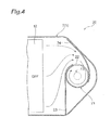
FIG 4 illustrates a modified example of a guide member of the exhaust gas purification device ofFIG. 1 , and is a cross-sectional view taken along the line II-II ofFIG. 1 . - Hereinafter, a preferred embodiment of the invention will be described in detail by referring to the drawings. Furthermore, the same reference numeral will be given to the same or equivalent component in the description below, and the repetitive description thereof will not be presented.
-
FIG. 1 is a view illustrating a schematic configuration of an exhaust gas purification device according to an embodiment. As illustrated inFIG. 1 , an exhaustgas purification device 10 of the embodiment is used to purify an exhaust gas (hereinafter, simply referred to as an "exhaust gas") discharged from an engine such as a diesel engine in, for example, a vehicle such as a truck. The exhaustgas purification device 10 is mounted on anexhaust passage 1 through which the exhaust gas circulates, and includes aDOC 11, aDPF 12, aninjection device 13, and anSCR 14. - The
exhaust passage 1 is partitioned by at least afirst casing 2, a pipe (wall portion) 3, and asecond casing 4 which are disposed in order from the upstream side toward the downstream side. Thefirst casing 2 and thesecond casing 4 are formed in a tube shape, and are provided in series so that the exhaust gas flow directions are substantially parallel to each other. Thepipe 3 connects the downstream side of thefirst casing 2 to the upstream side of thesecond casing 4. Thepipe 3 extends straightly in a direction substantially perpendicular to the length direction of thefirst casing 2, and extends so as to be curved toward the upstream side of thesecond casing 4. - The
DOC 11 is disposed at the upstream side inside thefirst casing 2 so as to perform an oxidation treatment on an unburned fuel fraction in the exhaust gas. TheDPF 12 is used to trap particulates (particulate substance) in the exhaust gas passing through theDOC 11, and is disposed at the downstream side of theDOC 11 inside thefirst casing 2. - The
injection device 13 is used to add a reduction agent to the exhaust gas directly after passing through theDPF 12 by injection. Theinjection device 13 herein produces ammonia by causing a thermal decomposition reaction and a hydrolysis reaction illustrated in the following equation (1) in a manner such that urea water is injected as the reduction agent.
(NH2)2CO → NH3 + HNCO (Thermal decomposition reaction) HNCO + H2O → NH3 + CO2 (Hydrolysis reaction) (1)
- The
SCR 14 is used to purify the exhaust gas by selectively causing a reduction reaction of NOx in the exhaust gas by the use of the added reduction agent. The SCR 14 is disposed inside thesecond casing 4. TheSCR 14 herein selectively reduces and purifies NOx by causing a reduction reaction illustrated in the following equation (2) by the use of the produced ammonia. Furthermore, the rear stage of thesecond casing 4 is provided with an ammonia reduction catalyst (not illustrated) that performs an oxidation treatment on extra ammonia.
4NO + 4NH3 + O2 → 4N2 + 6H2O (Standard)
6NO2 + 8NH3 → 7N2 + 12H2O (Slow) (2)
NO + NO2 + 2NH3 → 2N2 + 3H2O (Fast)
- Next, a main part of the exhaust
gas purification device 10 will be described in detail by referring toFIGS. 2 and3 .FIG. 2 is a view illustrating a main part of the exhaust gas purification device ofFIG. 1 , whereFIG. 2(a) is a cross-sectional view taken along the line II-II illustrated inFIG. 1 , andFIG. 2(b) is a perspective view visibly illustrating a connection portion between the first casing and the pipe.FIG. 3 is a partially enlarged view of the exhaust gas purification device ofFIG. 1 . Furthermore, for convenience of description, the upper side ofFIG. 2(a) is set as the right side, and the lower side ofFIG 2(a) is set as the left side. - As illustrated in
FIGS. 2 and3 , the upstream side of thepipe 3 is inserted into the downstream side of theDPF 12 in thefirst casing 2. The upstream side of thepipe 3 inserted into thefirst casing 2 extends in a direction substantially perpendicular to the axial direction of thefirst casing 2 so that the exhaust gas flow direction is substantially perpendicular to thefirst casing 2. Further, the upstream opening end of thepipe 3 is blocked by the wall surface of thefirst casing 2. Furthermore, the axial direction of thefirst casing 2 corresponds to the right and left direction ofFIG. 2(a) . - The
injection device 13 is attached to the upstream end of thepipe 3 so that the reduction agent is injected from the upstream end of thepipe 3 in the extension direction of thepipe 3. Theinjection device 13 is used to inject the reduction agent into thepipe 3. In other words, thepipe 3 includes an injection area A of the reduction agent injected from theinjection device 13. In theinjection device 13 herein, anozzle 13a is located at the center axis of thepipe 3, and injects the reduction agent toward the downstream side based on the center axis position of thepipe 3. - The upstream side of the
pipe 3 inserted into thefirst casing 2 is provided with a pair of through-holes holes pipe 3 from the inside to the outside thereof. - As illustrated in
FIG. 3 , the through-holes injection device 13 and aninner wall surface 3 a of thepipe 3. Furthermore, the injection area A has a substantially conical silhouette in which theinjection device 13 is the tip. The injection area A may be obtained geometrically based on, for example, the injection angle of the reduction agent injected from theinjection device 13. - Further, the through-
holes hole 15a is formed at the side of theDPF 12 in thepipe 3, and the through-hole 15b is formed at the opposite side to theDPF 12 in thepipe 3. Furthermore, when thefirst casing 2 is viewed from the upstream side toward the downstream side in the axial direction thereof, the reduction agent injection area A is visible from the through-hole 15a formed at the side of theDPF 12 in thepipe 3. - Here, as illustrated in
FIG. 2 , the exhaustgas purification device 10 of the embodiment includesguide members first casing 2 at the downstream side of theDPF 12 and guide the exhaust gas inside thefirst casing 2 to the through-holes - The
guide member 16a is used to cover the upstream side of the reduction agent injection area A in the axial direction of thefirst casing 2 and to guide the exhaust gas to the through-hole 15a from the tangential direction of thepipe 3 so as to generate a swirl flow inside thepipe 3. Theguide member 16a is a plate-shaped member that is curved so that the upstream side thereof is convex and the downstream side thereof is concave. Furthermore, in theguide member 16a, the upstream surface that is curved in a convex shape becomes the outer peripheral surface, and the downstream surface that is curved in a concave shape becomes the inner peripheral surface. Theguide member 16a is connected to the right side of the through-hole 15a in the circumferential direction of thepipe 3 when viewed from the injection direction of theinjection device 13, and extends while being expanded to the left side in the circumferential direction of thepipe 3 when viewed from the injection direction of theinjection device 13. That is, theguide member 16a covers the through-hole 15a from the upstream side of the through-hole 15a in the axial direction of thefirst casing 2 so that the diameter decreases as it goes toward the right side in the circumferential direction of thepipe 3 when viewed from the injection direction of theinjection device 13. - Since the
guide member 16b guides the exhaust gas flowing along the right side of theguide member 16a toward the inner peripheral surface of theguide member 16a, the exhaust gas is guided from the tangential direction of thepipe 3 to the through-hole 15a so as to generate the swirl flow inside thepipe 3. Theguide member 16b is a plate-shaped member that is curved so that the upstream side thereof is concave and the downstream side thereof is concave. Furthermore, in theguide member 16b, the upstream surface that is curved in a concave shape becomes the inner peripheral surface. Both ends of theguide member 16b are connected to the inner wall of thefirst casing 2 as the left side of thepipe 3 and the left side of the through-hole 15a in the circumferential direction of thepipe 3 when viewed from the injection direction of theinjection device 13. - The
guide member 16c is used to guide the exhaust gas from the tangential direction of thepipe 3 to the through-hole 15b so as to generate a swirl flow inside thepipe 3. Theguide member 16c is a plate-shaped member that is curved so that the upstream side thereof is concave and the downstream side thereof is concave. Furthermore, in theguide member 16c, the upstream surface that is curved in a concave shape becomes the inner peripheral surface. Theguide member 16c is connected to the right side of the through-hole 15b in the circumferential direction of thepipe 3 when viewed from the injection direction of theinjection device 13, and extends while being expanded toward the left side in the circumferential direction of thepipe 3 when viewed from the injection direction of theinjection device 13 so as to be connected to the inner wall of thefirst casing 2 as the right side of thepipe 3. That is, theguide member 16c covers the through-hole 15b so that the diameter decreases as it goes toward the right side in the circumferential direction of thepipe 3 when viewed from the injection direction of theinjection device 13. - As illustrated in
FIG. 1 , in the exhaustgas purification device 10 with the above-described configuration, an oxidation treatment is first performed on the exhaust gas from the engine by theDOC 11 inside thefirst casing 2, and the particulates inside the exhaust gas are trapped by theDPF 12. Then, as illustrated inFIG. 2(a) , the exhaust gas is guided by theguide members DPF 12, flows from the through-holes pipe 3, and flows so as to be substantially bent in the perpendicular direction by thepipe 3. - At this time, since the
guide member 16a covers the upstream side of the reduction agent injection area A in the axial direction of thefirst casing 2, the exhaust gas that flows toward theguide member 16a is divided into the right and left sides of thepipe 3 so as to bypass the through-hole 15a by the guide of theguide member 16a, and flows toward theguide member 16b and theguide member 16c. - The exhaust gas that flows toward the
guide member 16b flows toward the inner peripheral surface of theguide member 16a by the guide of the inner peripheral surface of theguide member 16b, and flows into thepipe 3 through the through-hole 15a from the tangential direction of thepipe 3 by the guide of the inner peripheral surface of theguide member 16a. For this reason, the exhaust gas that flows into thepipe 3 through the through-hole 15a turns rightward when viewed from the injection direction of theinjection device 13. - The exhaust gas that flows toward the
guide member 16c flows into thepipe 3 through the through-hole 15b from the tangential direction of thepipe 3. For this reason, the exhaust gas that flows into thepipe 3 through the through-hole 15b turns rightward when viewed from the injection direction of theinjection device 13 as in the exhaust gas that flows into thepipe 3 through the through-hole 15a. - The exhaust gas that flows from the through-
holes pipe 3 from the tangential direction, so that the swirl flow is generated around the center axis inside thepipe 3. Then, a reduction agent is injected from theinjection device 13 into the swirl flow of the exhaust gas so as to be added thereto, so that ammonia is produced by the thermal decomposition reaction and the hydrolysis reaction. - At this time, as described above, since the
guide member 16a covers the upstream side of the reduction agent injection area A in the axial direction of thefirst casing 2, it is possible to suppress the exhaust gas from directly entering the injection area A and to suppress the injected reduction agent from flowing by the flow of the exhaust gas. As a result, the injected reduction agent is sufficiently mixed with the exhaust gas while the shape of the injection area A is satisfactorily maintained and the injected reduction agent is nebulized (atomized) without adhering to the inner wall surface of thepipe 3. - Subsequently, as illustrated in
FIG. 1 , the exhaust gas including ammonia flows into thesecond casing 4, and NOx in the exhaust gas is purified while being selectively reduced by theSCR 14. Then, the exhaust gas is supplied to the ammonia reduction catalyst at the rear stage. - As described above, according to the embodiment, it is possible to diffuse the reduction agent by generating the swirl flow in the exhaust gas by the
guide members guide member 16a. For this reason, it is possible to suppress a problem in which the reduction agent injected from theinjection device 13 flows by the flow of the exhaust gas so that the reduction agent adheres to the inner wall surface of thepipe 3. Accordingly, it is possible to sufficiently diffuse the reduction agent. - Further, in the embodiment, since the through-
holes pipe 3 are formed at two positions, a sufficient opening area may be ensured, and hence the pressure (back pressure) of the exhaust gas may be reduced. In addition, since the exhaust gas is guided by theguide members holes pipe 3, and hence the swirl flow generated in the exhaust gas may be promoted. Accordingly, the reduction agent diffusion efficiency may be improved. That is, it is desirable that the through-holes be formed at two facing positions and the turning guide members guide the exhaust gas to the through-holes from the tangential direction of the pipe so as to generate the swirl flows in the same direction inside the pipe. In this way, since a sufficient opening area may be ensured compared to the case where the through-hole is formed at one position, the pressure (back pressure) of the exhaust gas may be reduced. In addition, since the exhaust gas is guided to the pair of through-holes by the turning guide members, the swirl flows may be generated in the same direction inside the pipe, and hence the swirl flow generated in the exhaust gas may be promoted. Accordingly, the reduction agent diffusion efficiency may be improved. - Further, in the embodiment, since the through-
holes inner wall surface 3a of thepipe 3, the swirl flow may be generated so as to surround the reduction agent injection area A by the exhaust gas flowing into thepipe 3, and hence the reduction agent may be further diffused. In addition, since the swirl flow may be generated in the exhaust gas by causing the exhaust gas to flow into thepipe 3 from the further upstream side, the reduction agent may be diffused directly after the injection. That is, it is desirable that the through-hole be formed at a position located at the upstream side of the matching position between the inner wall surface of the pipe and the injection area of the reduction agent injected from the injection device. In this way, since it is possible to generate the swirl flow so as to surround the reduction agent injection area by the exhaust gas flowing into the pipe, it is possible to further diffuse the reduction agent. Further, since it is possible to generate the swirl flow in the exhaust gas by causing the exhaust gas to flow into the pipe from the further upstream side, it is possible to diffuse the reduction agent directly after the injection. - While the preferred embodiment of one aspect of the invention has been described, the invention is not limited to the above-described embodiment. For example, the invention may be modified within a scope without departing from the spirit of claims and may be applied to the other embodiments.
- For example, in the above-described embodiment, a case has been described in which three through-holes are formed and three guide members are used, but the number of the through-holes or the guide members is not particularly limited. For example, as in an exhaust
gas purification device 20 illustrated inFIG. 4 , a configuration may be employed in which apipe 21 is provided with one through-hole 22 and twoguide members hole 22. In this case, oneguide member 23 may serve as a turning guide member that guides the exhaust gas to the through-hole 22 from the tangential direction of thepipe 21 so as to generate the swirl flow inside thepipe 21, and theother guide member 24 may serve as a protecting guide member that covers the upstream side of the reduction agent injection area A in the axial direction of thefirst casing 2. - Further, in the above-described embodiment, a case has been described in which the
guide member 16a serves as the turning guide member and the protecting guide member, and theguide members - Further, in the above-described embodiment, a truck is exemplified as the vehicle, but for example, a bus, a tractor, or the other vehicles may be exemplified. Furthermore, in the description above, the term of "substantially" allows the error in manufacture or design.
- The invention may be used as the exhaust gas purification device.
-
- 1 exhaust passage
- 2 first casing (casing)
- 3 pipe
- 3 a inner wall surface
- 4 second casing
- 10 exhaust gas purification device
- 13 injection device
- 13a nozzle
- 15a, 15b through-hole
- 16a, 16b, 16c guide member
- 20 exhaust gas purification device
- 21 pipe
- 22 through-hole
- 23, 24 guide member
- A injection area
Claims (3)
- An exhaust gas purification device that purifies an exhaust gas flowing through an exhaust passage of an engine, the exhaust gas purification device comprising:a tube-shaped casing;a pipe disposed at a downstream side of the casing, inserted into the casing so as to extend in a direction substantially perpendicular to an axial direction of the casing, and is provided with a through-hole communicating with the casing;a guide member for guiding the exhaust gas inside the casing to the through-hole; andan injection device for injecting into the pipe a reduction agent from an upstream end of the pipe,wherein the guide member includes a turning guide member guiding the exhaust gas to the through-hole from a tangential direction of the pipe so as to generate a swirl flow inside the pipe and a protecting guide member covering an upstream side of an injection area of the reduction agent in the axial direction of the casing.
- The exhaust gas purification device according to claim 1,
wherein the through-hole is formed at two facing positions, and
wherein the turning guide member guides the exhaust gas to the through-holes so as to generate inside the pipe the swirl flows in the same direction. - The exhaust gas purification device according to claim 1 or 2,
wherein the through-holes are formed at the upstream side of a matching position between the injection area of the reduction agent injected from the injection device and an inner wall surface of the pipe.
Applications Claiming Priority (2)
| Application Number | Priority Date | Filing Date | Title |
|---|---|---|---|
| JP2012004138A JP6053096B2 (en) | 2012-01-12 | 2012-01-12 | Exhaust purification device |
| PCT/JP2012/079366 WO2013105336A1 (en) | 2012-01-12 | 2012-11-13 | Exhaust gas purification device |
Publications (3)
| Publication Number | Publication Date |
|---|---|
| EP2803833A1 true EP2803833A1 (en) | 2014-11-19 |
| EP2803833A4 EP2803833A4 (en) | 2015-09-16 |
| EP2803833B1 EP2803833B1 (en) | 2017-08-16 |
Family
ID=48781300
Family Applications (1)
| Application Number | Title | Priority Date | Filing Date |
|---|---|---|---|
| EP12865222.9A Not-in-force EP2803833B1 (en) | 2012-01-12 | 2012-11-13 | Exhaust gas purification device |
Country Status (5)
| Country | Link |
|---|---|
| US (1) | US9604170B2 (en) |
| EP (1) | EP2803833B1 (en) |
| JP (1) | JP6053096B2 (en) |
| CN (1) | CN104040130B (en) |
| WO (1) | WO2013105336A1 (en) |
Cited By (3)
| Publication number | Priority date | Publication date | Assignee | Title |
|---|---|---|---|---|
| WO2016207484A1 (en) * | 2015-06-26 | 2016-12-29 | Proventia Emission Control Oy | Method, apparatus and mixing device for evenly mixing reactant to exhaust gas flow |
| FR3040193A1 (en) * | 2015-08-20 | 2017-02-24 | Peugeot Citroen Automobiles Sa | SELECTIVE CATALYTIC REDUCTION SYSTEM |
| FR3097775A1 (en) * | 2019-06-28 | 2021-01-01 | Faurecia Systemes D'echappement | Set of purification of an exhaust gas, exhaust line and vehicle |
Families Citing this family (27)
| Publication number | Priority date | Publication date | Assignee | Title |
|---|---|---|---|---|
| JP6053096B2 (en) | 2012-01-12 | 2016-12-27 | 日野自動車株式会社 | Exhaust purification device |
| JP6009260B2 (en) * | 2012-07-25 | 2016-10-19 | 日野自動車株式会社 | Exhaust purification device |
| DE102013108745A1 (en) * | 2013-08-13 | 2015-02-19 | Emitec Gesellschaft Für Emissionstechnologie Mbh | Exhaust gas treatment unit |
| EP3546058B1 (en) | 2013-09-13 | 2022-10-26 | Donaldson Company, Inc. | A mixing tube arrangement for use in exhaust aftertreatment |
| JP6185366B2 (en) | 2013-10-31 | 2017-08-23 | 日野自動車株式会社 | Exhaust purification device |
| JP6297323B2 (en) * | 2013-12-18 | 2018-03-20 | 日野自動車株式会社 | Exhaust purification device |
| JPWO2015151282A1 (en) * | 2014-04-04 | 2017-04-13 | フタバ産業株式会社 | Exhaust gas purification device |
| CN204511594U (en) * | 2015-02-27 | 2015-07-29 | 天纳克(苏州)排放系统有限公司 | Mixing tube and exhaust gas treatment device thereof |
| US9534525B2 (en) | 2015-05-27 | 2017-01-03 | Tenneco Automotive Operating Company Inc. | Mixer assembly for exhaust aftertreatment system |
| WO2017126121A1 (en) * | 2016-01-22 | 2017-07-27 | フタバ産業株式会社 | Mixing device |
| KR101744797B1 (en) * | 2016-03-07 | 2017-06-09 | 세종공업 주식회사 | Apparatus for mixing reducing agent |
| CN107435576B (en) * | 2016-05-27 | 2021-06-01 | 罗伯特·博世有限公司 | Integrated exhaust gas aftertreatment system |
| GB2539114A (en) * | 2016-07-05 | 2016-12-07 | Daimler Ag | Mixing device and aftertreatment device |
| GB2556890B (en) * | 2016-11-23 | 2019-02-20 | Proventia Oy | Method, apparatus and system for aftertreatment of exhaust gas comprising inline housing |
| JP6777568B2 (en) * | 2017-03-09 | 2020-10-28 | 日野自動車株式会社 | Exhaust purification device |
| JP6756644B2 (en) | 2017-03-09 | 2020-09-16 | 日野自動車株式会社 | Exhaust purification device |
| US10287948B1 (en) * | 2018-04-23 | 2019-05-14 | Faurecia Emissions Control Technologies, Usa, Llc | High efficiency mixer for vehicle exhaust system |
| DE202019100256U1 (en) * | 2019-01-17 | 2019-02-25 | Hjs Emission Technology Gmbh & Co. Kg | Means for supplying a chemical reagent in the exhaust line of an internal combustion engine |
| US10767537B1 (en) * | 2019-06-28 | 2020-09-08 | GM Global Technology Operations LLC | Hydrocarbon injector deflector assembly for diesel exhaust system |
| EP3812557B1 (en) | 2019-10-22 | 2023-01-25 | Purem GmbH | Mixer |
| DE102019130305A1 (en) * | 2019-10-22 | 2021-04-22 | Eberspächer Exhaust Technology GmbH | mixer |
| JP7382595B2 (en) * | 2019-11-12 | 2023-11-17 | 日立造船株式会社 | Rectifier, hydrolysis equipment, and denitrification equipment |
| CN110735693B (en) * | 2019-11-25 | 2021-05-11 | 无锡威孚力达催化净化器有限责任公司 | Urea mixer for exhaust aftertreatment |
| EP4242435A1 (en) | 2020-11-04 | 2023-09-13 | Tokyo Roki Co., Ltd. | Mixing device |
| DE102021121289A1 (en) * | 2021-08-17 | 2023-02-23 | Purem GmbH | Exhaust system for an internal combustion engine |
| CN115013128B (en) * | 2022-08-09 | 2023-03-21 | 潍柴动力股份有限公司 | SCR mixer and SCR system |
| JP2024031051A (en) * | 2022-08-25 | 2024-03-07 | ヤンマーホールディングス株式会社 | Aftertreatment equipment and engine |
Family Cites Families (29)
| Publication number | Priority date | Publication date | Assignee | Title |
|---|---|---|---|---|
| JPH0621555B2 (en) * | 1989-02-27 | 1994-03-23 | 神鋼電機株式会社 | Ammonia mixing device in denitration device |
| GB2381218B (en) | 2001-10-25 | 2004-12-15 | Eminox Ltd | Gas treatment apparatus |
| JP2006329019A (en) * | 2005-05-25 | 2006-12-07 | Hino Motors Ltd | Exhaust pipe of diesel engine |
| JP4928304B2 (en) | 2007-02-23 | 2012-05-09 | 日野自動車株式会社 | Exhaust purification device |
| JP4823944B2 (en) * | 2007-03-07 | 2011-11-24 | 日野自動車株式会社 | Exhaust purification device |
| JP5132187B2 (en) | 2007-05-18 | 2013-01-30 | Udトラックス株式会社 | Exhaust purification device |
| DE202008001547U1 (en) | 2007-07-24 | 2008-04-10 | Emcon Technologies Germany (Augsburg) Gmbh | Assembly for introducing a reducing agent into the exhaust pipe of an exhaust system of an internal combustion engine |
| JP2009097435A (en) * | 2007-10-17 | 2009-05-07 | Mitsubishi Fuso Truck & Bus Corp | Exhaust emission control device |
| DE102008050357A1 (en) | 2007-10-09 | 2009-04-30 | Mitsubishi Fuso Truck and Bus Corp., Kawasaki | Exhaust gas purification device for a motor |
| JP4928409B2 (en) | 2007-10-23 | 2012-05-09 | 日野自動車株式会社 | Exhaust purification device |
| JP5017065B2 (en) * | 2007-11-21 | 2012-09-05 | 日野自動車株式会社 | Exhaust purification device |
| JP5090890B2 (en) * | 2007-12-21 | 2012-12-05 | 三菱ふそうトラック・バス株式会社 | Engine exhaust purification system |
| JP4332756B2 (en) | 2007-12-25 | 2009-09-16 | 三菱自動車工業株式会社 | Exhaust gas purification device for internal combustion engine |
| FR2928687B1 (en) | 2008-03-12 | 2013-07-26 | Faurecia Sys Echappement | EXHAUST LINE WITH REAGENT INJECTOR |
| JP4951560B2 (en) | 2008-03-19 | 2012-06-13 | 東京濾器株式会社 | Exhaust gas purification device for internal combustion engine |
| EP2295756B1 (en) | 2008-05-27 | 2014-03-05 | Hino Motors Ltd. | Exhaust emission control device |
| JP2010084700A (en) | 2008-10-01 | 2010-04-15 | Toyota Motor Corp | Exhaust emission control device and method for manufacturing the exhaust emission control device |
| JP2011064069A (en) | 2009-09-15 | 2011-03-31 | Toyota Industries Corp | Exhaust gas treatment system |
| US8240137B2 (en) | 2009-10-27 | 2012-08-14 | Cummins Filtration Ip, Inc. | Reductant injection and decomposition system |
| JP2011099390A (en) | 2009-11-06 | 2011-05-19 | Mitsubishi Fuso Truck & Bus Corp | Exhaust emission control device of engine |
| JP5329383B2 (en) * | 2009-12-24 | 2013-10-30 | 日野自動車株式会社 | Exhaust purification device |
| WO2011110885A1 (en) | 2010-03-11 | 2011-09-15 | Renault Trucks | Mixing system for an exhaust gas after-treatment arrangement |
| JP5602495B2 (en) | 2010-05-25 | 2014-10-08 | いすゞ自動車株式会社 | Exhaust gas purification device |
| EP3267005B2 (en) * | 2010-06-22 | 2023-12-27 | Donaldson Company, Inc. | Exhaust aftertreatment device |
| KR101251518B1 (en) * | 2010-12-09 | 2013-04-05 | 기아자동차주식회사 | Dosing module for exhaust after-treatment system of vehicle |
| DE102011077155C5 (en) * | 2011-06-07 | 2022-04-14 | Robert Bosch Gmbh | exhaust system |
| EP2607641A1 (en) * | 2011-12-19 | 2013-06-26 | Mtu Friedrichshafen Gmbh | Mixer device for introducing a reducing agent to an exhaust gas flow with blade-shaped means |
| JP6053096B2 (en) | 2012-01-12 | 2016-12-27 | 日野自動車株式会社 | Exhaust purification device |
| US9062589B2 (en) * | 2013-01-17 | 2015-06-23 | Komatsu Ltd. | Reductant aqueous solution mixing device and exhaust aftertreatment device provided with the same |
-
2012
- 2012-01-12 JP JP2012004138A patent/JP6053096B2/en not_active Expired - Fee Related
- 2012-11-13 EP EP12865222.9A patent/EP2803833B1/en not_active Not-in-force
- 2012-11-13 CN CN201280066828.6A patent/CN104040130B/en not_active Expired - Fee Related
- 2012-11-13 US US14/371,882 patent/US9604170B2/en not_active Expired - Fee Related
- 2012-11-13 WO PCT/JP2012/079366 patent/WO2013105336A1/en active Application Filing
Cited By (4)
| Publication number | Priority date | Publication date | Assignee | Title |
|---|---|---|---|---|
| WO2016207484A1 (en) * | 2015-06-26 | 2016-12-29 | Proventia Emission Control Oy | Method, apparatus and mixing device for evenly mixing reactant to exhaust gas flow |
| US10252225B2 (en) | 2015-06-26 | 2019-04-09 | Proventia Oy | Method, apparatus and mixing device for evenly mixing reactant to exhaust gas flow |
| FR3040193A1 (en) * | 2015-08-20 | 2017-02-24 | Peugeot Citroen Automobiles Sa | SELECTIVE CATALYTIC REDUCTION SYSTEM |
| FR3097775A1 (en) * | 2019-06-28 | 2021-01-01 | Faurecia Systemes D'echappement | Set of purification of an exhaust gas, exhaust line and vehicle |
Also Published As
| Publication number | Publication date |
|---|---|
| CN104040130A (en) | 2014-09-10 |
| JP2013142368A (en) | 2013-07-22 |
| EP2803833A4 (en) | 2015-09-16 |
| WO2013105336A1 (en) | 2013-07-18 |
| US9604170B2 (en) | 2017-03-28 |
| EP2803833B1 (en) | 2017-08-16 |
| JP6053096B2 (en) | 2016-12-27 |
| CN104040130B (en) | 2017-09-26 |
| US20150020484A1 (en) | 2015-01-22 |
Similar Documents
| Publication | Publication Date | Title |
|---|---|---|
| US9604170B2 (en) | Exhaust gas purification device | |
| JP5985822B2 (en) | Exhaust purification device | |
| JP6009260B2 (en) | Exhaust purification device | |
| EP3093463B1 (en) | Exhaust purification device | |
| JP4779959B2 (en) | Exhaust purification device | |
| JP4286888B2 (en) | Exhaust purification equipment | |
| JP4286887B2 (en) | Exhaust purification equipment | |
| EP3575566A1 (en) | Exhaust gas purification device | |
| WO2015126353A1 (en) | Plenum chamber for exhaust system | |
| EP3438426A1 (en) | Exhaust purification system | |
| JP5057944B2 (en) | Exhaust aftertreatment device | |
| JP2018105248A (en) | Exhaust emission control device | |
| EP2075051B1 (en) | Apparatus for reducing nitrogen oxide in exhaust pipes | |
| KR20140062869A (en) | Mixer of selective catalyst reduction device for exhaust system | |
| JP2013142372A (en) | Exhaust emission control device | |
| JP2014040814A (en) | Exhaust emission control device | |
| JP2015209799A (en) | Internal combustion engine exhaust emission control system |
Legal Events
| Date | Code | Title | Description |
|---|---|---|---|
| PUAI | Public reference made under article 153(3) epc to a published international application that has entered the european phase |
Free format text: ORIGINAL CODE: 0009012 |
|
| 17P | Request for examination filed |
Effective date: 20140812 |
|
| AK | Designated contracting states |
Kind code of ref document: A1 Designated state(s): AL AT BE BG CH CY CZ DE DK EE ES FI FR GB GR HR HU IE IS IT LI LT LU LV MC MK MT NL NO PL PT RO RS SE SI SK SM TR |
|
| DAX | Request for extension of the european patent (deleted) | ||
| RA4 | Supplementary search report drawn up and despatched (corrected) |
Effective date: 20150814 |
|
| RIC1 | Information provided on ipc code assigned before grant |
Ipc: B01F 3/04 20060101ALI20150810BHEP Ipc: B01F 5/00 20060101AFI20150810BHEP Ipc: B01F 5/04 20060101ALI20150810BHEP Ipc: F01N 3/035 20060101ALN20150810BHEP Ipc: F01N 3/10 20060101ALN20150810BHEP Ipc: F01N 3/20 20060101ALN20150810BHEP Ipc: F01N 3/28 20060101ALI20150810BHEP |
|
| GRAP | Despatch of communication of intention to grant a patent |
Free format text: ORIGINAL CODE: EPIDOSNIGR1 |
|
| RIC1 | Information provided on ipc code assigned before grant |
Ipc: B01F 5/04 20060101ALI20160907BHEP Ipc: F01N 3/28 20060101ALI20160907BHEP Ipc: F01N 3/10 20060101ALN20160907BHEP Ipc: F01N 3/20 20060101ALN20160907BHEP Ipc: B01F 5/00 20060101AFI20160907BHEP Ipc: B01F 3/04 20060101ALI20160907BHEP Ipc: B01D 45/16 20060101ALI20160907BHEP Ipc: F01N 3/035 20060101ALN20160907BHEP |
|
| INTG | Intention to grant announced |
Effective date: 20161013 |
|
| GRAJ | Information related to disapproval of communication of intention to grant by the applicant or resumption of examination proceedings by the epo deleted |
Free format text: ORIGINAL CODE: EPIDOSDIGR1 |
|
| REG | Reference to a national code |
Ref country code: DE Ref legal event code: R079 Ref document number: 602012036140 Country of ref document: DE Free format text: PREVIOUS MAIN CLASS: F01N0003240000 Ipc: B01F0005000000 |
|
| STAA | Information on the status of an ep patent application or granted ep patent |
Free format text: STATUS: REQUEST FOR EXAMINATION WAS MADE |
|
| GRAP | Despatch of communication of intention to grant a patent |
Free format text: ORIGINAL CODE: EPIDOSNIGR1 |
|
| STAA | Information on the status of an ep patent application or granted ep patent |
Free format text: STATUS: GRANT OF PATENT IS INTENDED |
|
| INTC | Intention to grant announced (deleted) | ||
| RIC1 | Information provided on ipc code assigned before grant |
Ipc: F01N 3/035 20060101ALN20170214BHEP Ipc: F01N 3/10 20060101ALN20170214BHEP Ipc: B01D 45/16 20060101ALI20170214BHEP Ipc: B01F 5/00 20060101AFI20170214BHEP Ipc: F01N 3/28 20060101ALI20170214BHEP Ipc: B01F 3/04 20060101ALI20170214BHEP Ipc: F01N 3/20 20060101ALN20170214BHEP Ipc: B01F 5/04 20060101ALI20170214BHEP |
|
| INTG | Intention to grant announced |
Effective date: 20170302 |
|
| GRAS | Grant fee paid |
Free format text: ORIGINAL CODE: EPIDOSNIGR3 |
|
| GRAA | (expected) grant |
Free format text: ORIGINAL CODE: 0009210 |
|
| STAA | Information on the status of an ep patent application or granted ep patent |
Free format text: STATUS: THE PATENT HAS BEEN GRANTED |
|
| AK | Designated contracting states |
Kind code of ref document: B1 Designated state(s): AL AT BE BG CH CY CZ DE DK EE ES FI FR GB GR HR HU IE IS IT LI LT LU LV MC MK MT NL NO PL PT RO RS SE SI SK SM TR |
|
| REG | Reference to a national code |
Ref country code: GB Ref legal event code: FG4D |
|
| REG | Reference to a national code |
Ref country code: CH Ref legal event code: EP |
|
| REG | Reference to a national code |
Ref country code: IE Ref legal event code: FG4D |
|
| REG | Reference to a national code |
Ref country code: AT Ref legal event code: REF Ref document number: 918527 Country of ref document: AT Kind code of ref document: T Effective date: 20170915 |
|
| REG | Reference to a national code |
Ref country code: DE Ref legal event code: R096 Ref document number: 602012036140 Country of ref document: DE |
|
| REG | Reference to a national code |
Ref country code: NL Ref legal event code: MP Effective date: 20170816 |
|
| REG | Reference to a national code |
Ref country code: LT Ref legal event code: MG4D |
|
| REG | Reference to a national code |
Ref country code: AT Ref legal event code: MK05 Ref document number: 918527 Country of ref document: AT Kind code of ref document: T Effective date: 20170816 |
|
| PG25 | Lapsed in a contracting state [announced via postgrant information from national office to epo] |
Ref country code: FI Free format text: LAPSE BECAUSE OF FAILURE TO SUBMIT A TRANSLATION OF THE DESCRIPTION OR TO PAY THE FEE WITHIN THE PRESCRIBED TIME-LIMIT Effective date: 20170816 Ref country code: NL Free format text: LAPSE BECAUSE OF FAILURE TO SUBMIT A TRANSLATION OF THE DESCRIPTION OR TO PAY THE FEE WITHIN THE PRESCRIBED TIME-LIMIT Effective date: 20170816 Ref country code: LT Free format text: LAPSE BECAUSE OF FAILURE TO SUBMIT A TRANSLATION OF THE DESCRIPTION OR TO PAY THE FEE WITHIN THE PRESCRIBED TIME-LIMIT Effective date: 20170816 Ref country code: NO Free format text: LAPSE BECAUSE OF FAILURE TO SUBMIT A TRANSLATION OF THE DESCRIPTION OR TO PAY THE FEE WITHIN THE PRESCRIBED TIME-LIMIT Effective date: 20171116 Ref country code: SE Free format text: LAPSE BECAUSE OF FAILURE TO SUBMIT A TRANSLATION OF THE DESCRIPTION OR TO PAY THE FEE WITHIN THE PRESCRIBED TIME-LIMIT Effective date: 20170816 Ref country code: AT Free format text: LAPSE BECAUSE OF FAILURE TO SUBMIT A TRANSLATION OF THE DESCRIPTION OR TO PAY THE FEE WITHIN THE PRESCRIBED TIME-LIMIT Effective date: 20170816 |
|
| PG25 | Lapsed in a contracting state [announced via postgrant information from national office to epo] |
Ref country code: IS Free format text: LAPSE BECAUSE OF FAILURE TO SUBMIT A TRANSLATION OF THE DESCRIPTION OR TO PAY THE FEE WITHIN THE PRESCRIBED TIME-LIMIT Effective date: 20171216 Ref country code: ES Free format text: LAPSE BECAUSE OF FAILURE TO SUBMIT A TRANSLATION OF THE DESCRIPTION OR TO PAY THE FEE WITHIN THE PRESCRIBED TIME-LIMIT Effective date: 20170816 Ref country code: GR Free format text: LAPSE BECAUSE OF FAILURE TO SUBMIT A TRANSLATION OF THE DESCRIPTION OR TO PAY THE FEE WITHIN THE PRESCRIBED TIME-LIMIT Effective date: 20171117 Ref country code: PL Free format text: LAPSE BECAUSE OF FAILURE TO SUBMIT A TRANSLATION OF THE DESCRIPTION OR TO PAY THE FEE WITHIN THE PRESCRIBED TIME-LIMIT Effective date: 20170816 Ref country code: BG Free format text: LAPSE BECAUSE OF FAILURE TO SUBMIT A TRANSLATION OF THE DESCRIPTION OR TO PAY THE FEE WITHIN THE PRESCRIBED TIME-LIMIT Effective date: 20171116 Ref country code: LV Free format text: LAPSE BECAUSE OF FAILURE TO SUBMIT A TRANSLATION OF THE DESCRIPTION OR TO PAY THE FEE WITHIN THE PRESCRIBED TIME-LIMIT Effective date: 20170816 Ref country code: RS Free format text: LAPSE BECAUSE OF FAILURE TO SUBMIT A TRANSLATION OF THE DESCRIPTION OR TO PAY THE FEE WITHIN THE PRESCRIBED TIME-LIMIT Effective date: 20170816 |
|
| PG25 | Lapsed in a contracting state [announced via postgrant information from national office to epo] |
Ref country code: CZ Free format text: LAPSE BECAUSE OF FAILURE TO SUBMIT A TRANSLATION OF THE DESCRIPTION OR TO PAY THE FEE WITHIN THE PRESCRIBED TIME-LIMIT Effective date: 20170816 Ref country code: DK Free format text: LAPSE BECAUSE OF FAILURE TO SUBMIT A TRANSLATION OF THE DESCRIPTION OR TO PAY THE FEE WITHIN THE PRESCRIBED TIME-LIMIT Effective date: 20170816 Ref country code: RO Free format text: LAPSE BECAUSE OF FAILURE TO SUBMIT A TRANSLATION OF THE DESCRIPTION OR TO PAY THE FEE WITHIN THE PRESCRIBED TIME-LIMIT Effective date: 20170816 |
|
| REG | Reference to a national code |
Ref country code: DE Ref legal event code: R097 Ref document number: 602012036140 Country of ref document: DE |
|
| PG25 | Lapsed in a contracting state [announced via postgrant information from national office to epo] |
Ref country code: SM Free format text: LAPSE BECAUSE OF FAILURE TO SUBMIT A TRANSLATION OF THE DESCRIPTION OR TO PAY THE FEE WITHIN THE PRESCRIBED TIME-LIMIT Effective date: 20170816 Ref country code: EE Free format text: LAPSE BECAUSE OF FAILURE TO SUBMIT A TRANSLATION OF THE DESCRIPTION OR TO PAY THE FEE WITHIN THE PRESCRIBED TIME-LIMIT Effective date: 20170816 Ref country code: SK Free format text: LAPSE BECAUSE OF FAILURE TO SUBMIT A TRANSLATION OF THE DESCRIPTION OR TO PAY THE FEE WITHIN THE PRESCRIBED TIME-LIMIT Effective date: 20170816 Ref country code: IT Free format text: LAPSE BECAUSE OF FAILURE TO SUBMIT A TRANSLATION OF THE DESCRIPTION OR TO PAY THE FEE WITHIN THE PRESCRIBED TIME-LIMIT Effective date: 20170816 |
|
| PLBE | No opposition filed within time limit |
Free format text: ORIGINAL CODE: 0009261 |
|
| STAA | Information on the status of an ep patent application or granted ep patent |
Free format text: STATUS: NO OPPOSITION FILED WITHIN TIME LIMIT |
|
| PG25 | Lapsed in a contracting state [announced via postgrant information from national office to epo] |
Ref country code: MC Free format text: LAPSE BECAUSE OF FAILURE TO SUBMIT A TRANSLATION OF THE DESCRIPTION OR TO PAY THE FEE WITHIN THE PRESCRIBED TIME-LIMIT Effective date: 20170816 |
|
| 26N | No opposition filed |
Effective date: 20180517 |
|
| PG25 | Lapsed in a contracting state [announced via postgrant information from national office to epo] |
Ref country code: LI Free format text: LAPSE BECAUSE OF NON-PAYMENT OF DUE FEES Effective date: 20171130 Ref country code: CH Free format text: LAPSE BECAUSE OF NON-PAYMENT OF DUE FEES Effective date: 20171130 |
|
| PG25 | Lapsed in a contracting state [announced via postgrant information from national office to epo] |
Ref country code: LU Free format text: LAPSE BECAUSE OF NON-PAYMENT OF DUE FEES Effective date: 20171113 Ref country code: SI Free format text: LAPSE BECAUSE OF FAILURE TO SUBMIT A TRANSLATION OF THE DESCRIPTION OR TO PAY THE FEE WITHIN THE PRESCRIBED TIME-LIMIT Effective date: 20170816 |
|
| REG | Reference to a national code |
Ref country code: FR Ref legal event code: ST Effective date: 20180731 Ref country code: BE Ref legal event code: MM Effective date: 20171130 |
|
| REG | Reference to a national code |
Ref country code: IE Ref legal event code: MM4A |
|
| PG25 | Lapsed in a contracting state [announced via postgrant information from national office to epo] |
Ref country code: MT Free format text: LAPSE BECAUSE OF NON-PAYMENT OF DUE FEES Effective date: 20171113 |
|
| PG25 | Lapsed in a contracting state [announced via postgrant information from national office to epo] |
Ref country code: FR Free format text: LAPSE BECAUSE OF NON-PAYMENT OF DUE FEES Effective date: 20171130 Ref country code: IE Free format text: LAPSE BECAUSE OF NON-PAYMENT OF DUE FEES Effective date: 20171113 |
|
| PG25 | Lapsed in a contracting state [announced via postgrant information from national office to epo] |
Ref country code: BE Free format text: LAPSE BECAUSE OF NON-PAYMENT OF DUE FEES Effective date: 20171130 |
|
| PGFP | Annual fee paid to national office [announced via postgrant information from national office to epo] |
Ref country code: DE Payment date: 20181030 Year of fee payment: 7 |
|
| PGFP | Annual fee paid to national office [announced via postgrant information from national office to epo] |
Ref country code: GB Payment date: 20181115 Year of fee payment: 7 |
|
| PG25 | Lapsed in a contracting state [announced via postgrant information from national office to epo] |
Ref country code: HU Free format text: LAPSE BECAUSE OF FAILURE TO SUBMIT A TRANSLATION OF THE DESCRIPTION OR TO PAY THE FEE WITHIN THE PRESCRIBED TIME-LIMIT; INVALID AB INITIO Effective date: 20121113 |
|
| PG25 | Lapsed in a contracting state [announced via postgrant information from national office to epo] |
Ref country code: CY Free format text: LAPSE BECAUSE OF FAILURE TO SUBMIT A TRANSLATION OF THE DESCRIPTION OR TO PAY THE FEE WITHIN THE PRESCRIBED TIME-LIMIT Effective date: 20170816 |
|
| PG25 | Lapsed in a contracting state [announced via postgrant information from national office to epo] |
Ref country code: MK Free format text: LAPSE BECAUSE OF FAILURE TO SUBMIT A TRANSLATION OF THE DESCRIPTION OR TO PAY THE FEE WITHIN THE PRESCRIBED TIME-LIMIT Effective date: 20170816 |
|
| PG25 | Lapsed in a contracting state [announced via postgrant information from national office to epo] |
Ref country code: TR Free format text: LAPSE BECAUSE OF FAILURE TO SUBMIT A TRANSLATION OF THE DESCRIPTION OR TO PAY THE FEE WITHIN THE PRESCRIBED TIME-LIMIT Effective date: 20170816 |
|
| PG25 | Lapsed in a contracting state [announced via postgrant information from national office to epo] |
Ref country code: PT Free format text: LAPSE BECAUSE OF FAILURE TO SUBMIT A TRANSLATION OF THE DESCRIPTION OR TO PAY THE FEE WITHIN THE PRESCRIBED TIME-LIMIT Effective date: 20170816 |
|
| REG | Reference to a national code |
Ref country code: DE Ref legal event code: R119 Ref document number: 602012036140 Country of ref document: DE |
|
| PG25 | Lapsed in a contracting state [announced via postgrant information from national office to epo] |
Ref country code: HR Free format text: LAPSE BECAUSE OF FAILURE TO SUBMIT A TRANSLATION OF THE DESCRIPTION OR TO PAY THE FEE WITHIN THE PRESCRIBED TIME-LIMIT Effective date: 20170816 |
|
| PG25 | Lapsed in a contracting state [announced via postgrant information from national office to epo] |
Ref country code: AL Free format text: LAPSE BECAUSE OF FAILURE TO SUBMIT A TRANSLATION OF THE DESCRIPTION OR TO PAY THE FEE WITHIN THE PRESCRIBED TIME-LIMIT Effective date: 20170816 |
|
| GBPC | Gb: european patent ceased through non-payment of renewal fee |
Effective date: 20191113 |
|
| PG25 | Lapsed in a contracting state [announced via postgrant information from national office to epo] |
Ref country code: DE Free format text: LAPSE BECAUSE OF NON-PAYMENT OF DUE FEES Effective date: 20200603 Ref country code: GB Free format text: LAPSE BECAUSE OF NON-PAYMENT OF DUE FEES Effective date: 20191113 |