EP2803829A1 - Flexible cam follower - Google Patents
Flexible cam follower Download PDFInfo
- Publication number
- EP2803829A1 EP2803829A1 EP13167689.2A EP13167689A EP2803829A1 EP 2803829 A1 EP2803829 A1 EP 2803829A1 EP 13167689 A EP13167689 A EP 13167689A EP 2803829 A1 EP2803829 A1 EP 2803829A1
- Authority
- EP
- European Patent Office
- Prior art keywords
- cam follower
- camshaft
- cam
- actuator
- assembly
- Prior art date
- Legal status (The legal status is an assumption and is not a legal conclusion. Google has not performed a legal analysis and makes no representation as to the accuracy of the status listed.)
- Withdrawn
Links
Images



Classifications
-
- F—MECHANICAL ENGINEERING; LIGHTING; HEATING; WEAPONS; BLASTING
- F01—MACHINES OR ENGINES IN GENERAL; ENGINE PLANTS IN GENERAL; STEAM ENGINES
- F01L—CYCLICALLY OPERATING VALVES FOR MACHINES OR ENGINES
- F01L13/00—Modifications of valve-gear to facilitate reversing, braking, starting, changing compression ratio, or other specific operations
- F01L13/0015—Modifications of valve-gear to facilitate reversing, braking, starting, changing compression ratio, or other specific operations for optimising engine performances by modifying valve lift according to various working parameters, e.g. rotational speed, load, torque
- F01L13/0063—Modifications of valve-gear to facilitate reversing, braking, starting, changing compression ratio, or other specific operations for optimising engine performances by modifying valve lift according to various working parameters, e.g. rotational speed, load, torque by modification of cam contact point by displacing an intermediate lever or wedge-shaped intermediate element, e.g. Tourtelot
-
- F—MECHANICAL ENGINEERING; LIGHTING; HEATING; WEAPONS; BLASTING
- F01—MACHINES OR ENGINES IN GENERAL; ENGINE PLANTS IN GENERAL; STEAM ENGINES
- F01L—CYCLICALLY OPERATING VALVES FOR MACHINES OR ENGINES
- F01L13/00—Modifications of valve-gear to facilitate reversing, braking, starting, changing compression ratio, or other specific operations
- F01L13/0015—Modifications of valve-gear to facilitate reversing, braking, starting, changing compression ratio, or other specific operations for optimising engine performances by modifying valve lift according to various working parameters, e.g. rotational speed, load, torque
- F01L13/0021—Modifications of valve-gear to facilitate reversing, braking, starting, changing compression ratio, or other specific operations for optimising engine performances by modifying valve lift according to various working parameters, e.g. rotational speed, load, torque by modification of rocker arm ratio
-
- F—MECHANICAL ENGINEERING; LIGHTING; HEATING; WEAPONS; BLASTING
- F01—MACHINES OR ENGINES IN GENERAL; ENGINE PLANTS IN GENERAL; STEAM ENGINES
- F01L—CYCLICALLY OPERATING VALVES FOR MACHINES OR ENGINES
- F01L13/00—Modifications of valve-gear to facilitate reversing, braking, starting, changing compression ratio, or other specific operations
- F01L13/0015—Modifications of valve-gear to facilitate reversing, braking, starting, changing compression ratio, or other specific operations for optimising engine performances by modifying valve lift according to various working parameters, e.g. rotational speed, load, torque
- F01L13/0021—Modifications of valve-gear to facilitate reversing, braking, starting, changing compression ratio, or other specific operations for optimising engine performances by modifying valve lift according to various working parameters, e.g. rotational speed, load, torque by modification of rocker arm ratio
- F01L13/0026—Modifications of valve-gear to facilitate reversing, braking, starting, changing compression ratio, or other specific operations for optimising engine performances by modifying valve lift according to various working parameters, e.g. rotational speed, load, torque by modification of rocker arm ratio by means of an eccentric
Definitions
- the present disclosure relates to a method and device for controlling the operation of an internal combustion engine, and more particularly to a method and device for controlling a component controlled by an operating lifter supported by a cam follower which follows a cam of a camshaft.
- EP 2 136 054 Al discloses a device for controlling the operation of an engine equipped with a rotatable shaft provided with three eccentrics. Each eccentric supports an operating lever.
- a first eccentric supports an inlet valve operating lever formed, for example, as an oscillating arm, which may trace a stroke of an inlet cam via, for example, a roll supported thereon, and may transmit it to the inlet valve via, for example, an inlet valve operating lifter in order to operate the inlet valve.
- a second eccentric supports an outlet valve operating lever, which may trace the stroke of an outlet cam via, for example, a roll supported thereon, and transmit it to an outlet valve operating lifter.
- a stroke of a fuel pump cam may be traced, for example, by a roll arranged at the end of a pump operating lever and transmitted to a pump piston via, for example, a pressure spring.
- the pump operating lever is supported on the third eccentric.
- the eccentrics may be formed integrally with the rotatable shaft.
- the eccentricities of the preferably circular cylindrical circumferential surfaces of the eccentrics relative to the axis of the rotatable shaft, as well as the relative position of the eccentricities relative to the rotational position of the shaft may be selected individually according to the respective requirements.
- An actuator and gear wheels form an actuator unit.
- the diesel engine is operated at a load greater than 25 % of the full load with two valve lifting curves, for example, in a Miller cycle.
- the shaft is turned, so that the engine is operated with two different valve lifting curves.
- This technology is also known as flexible camshaft technology (FCT).
- the present disclosure is directed, at least in part, to improving or overcoming one or more aspects of prior systems.
- a cam follower assembly for controlling the operation of an internal combustion engine comprising a camshaft rotatable about a camshaft axis, the camshaft being provided with at least one cam, is dislosed.
- the cam follower assembly may comprise a cam follower configured to follow one cam, a cam follower support pivotable about a pivot axis spaced apart from the camshaft axis, the cam follower support supporting the cam follower, and an actuator which may be interposed between the cam follower and the cam follower support and configured to displace the cam follower in a direction perpendicular to the camshaft axis.
- a device for controlling the operation of an internal combustion engine comprising a camshaft rotatable about a camshaft axis, the camshaft being provided with a plurality of cams.
- the device may comprise a plurality of cam follower assemblies as exemplary disclosed herein, each cam follower of the plurality of cam follower assemblies following one of the plurality of cams.
- a method for controlling the operation of an internal combustion engine comprising a camshaft rotatable about a camshaft axis, the camshaft being provided with at least one cam, is disclosed.
- the method may comprise providing a cam follower assembly as exemplary disclosed herein, rotating the camshaft about the camshaft axis, changing the actuation time of a component operated by an operating lifter supported by the cam follower by displacing the cam follower in a direction perpendicular to the camshaft axis via the actuator.
- hydraulic circuits can be introduced in the field FCT.
- Said hydraulic circuits may allow increasing a degree of control over actuation timing of components operated by a camshaft such as inlet valves, outlet valves, gas valves, and fuel pumps.
- hydraulic circuits may be implemented in FCT such that individual control of components operated by the same camshaft is facilitated.
- hydraulic circuits may be implemented in FCT to provide a continuous control range to control components.
- a pneumatic actuator being part of a pneumatic circuit, or an electrical actuator being part of an electrical circuit may be provided.
- a cam follower assembly which utilizes an actuator to facilitate a change in the actuation timing of a component operated by a cam follower of the cam follower assembly via a displacement of the cam follower relative to the camshaft.
- the actuator may be embodied as hydraulic actuator, pneumatic actuator, or electrical actuator.
- a not illustrated internal combustion engine which may be charged via an exhaust gas turbocharger (not shown), is provided, including a camshaft 10 (shown only in part).
- Camshaft 10 is provided with at least one cam 12 which may be formed integrally with camshaft 10.
- Camshaft 10 is rotatably supported and rotatable about a camshaft axis A. Additionally, cam shaft 10 may comprise further cams (not shown) such that cam shaft 12 is provided with a plurality of cams.
- Said internal combustion engine comprising camshaft 10 may include features not shown, such as air systems, cooling systems, peripheries, drivetrain components, etc.
- the internal combustion engine may be of any size, with any number of cylinders, and in any configuration (for example, "V," in-line, radial, etc.).
- internal combustion engine may be used to power any machine or other device, including, but not limited to, locomotive applications, on-highway trucks or vehicles, off-highway trucks or machines, earth moving equipment, generators, aerospace applications, marine applications, offshore applications, pumps, stationary equipment, or other engine powered applications.
- Internal combustion engine may be powered with any fuel including, but not limited to, diesel, gasoline, and/or gaseous fuels.
- said internal combustion engine may be a dual fuel engine capable to run on a liquid fuel and/or a gaseous fuel, or may be an engine capable to run on various liquid fuels such as diesel and heavy fuel oil.
- Cam 12 is adapted to operate a component of the internal combustion engine via a cam follower assembly 14 and an operating lifter 16.
- the component may be, for example, an inlet valve, an outlet valve, a gas valve or a fuel pump.
- Cam follower assembly 14 for controlling the operation of the internal combustion engine comprises a cam follower 18, a cam follower support 20, and an actuator 22.
- Cam follower 18 is configured to follow cam 12 by tracing the stroke of cam 12 via, for example, a roll 24 supported thereon and transmitting the same to the component via the operating lifter 16 supported on cam follower 18 to control the component.
- cam follower support 20 is pivotably supported via, for example, a support shaft 23 such that cam follower support 20 is pivotable about a pivot axis B which is spaced apart from camshaft axis A, for example, parallely arranged spaced apart from camshaft axis A.
- Cam follower support 20 supports cam follower 18 via, for example, at least one guiding pin, two of which are shown in the embodiment shown in Fig. 1 and are referenced with reference numerals 26 and 28, respectively.
- cam follower 18 can be guided during displacement caused by actuator 22.
- Guiding pins 26 and 28 may be rigidly fixed to cam follower support 20 or to cam follower 18, and may be slideable within guiding pin recesses (not shown) within cam follower 18 or cam follower support 20, respectively.
- guiding pins 26 and 28 are provided with a circular cross-section.
- guiding pins 26 and 28 may have any other suitable cross-section including, but not limited to, a square cross-section, and a rectangular cross-section.
- cam follower assembly 14 may not comprise any guiding pin, and support of cam follower 18 may be realized via actuator 22.
- actuator 22 is provided which is interposed between cam follower 18 and cam follower support 20 and configured to displace cam follower 18 in a direction perpendicular to camshaft axis A to change an actuation timing of a component operated by an operating lifter supported by cam follower 18 tracing cam 12 of camshaft 10 during rotation of camshaft 10.
- Perpendicular as used herein may refer to substantially perpendicular including those degree values around 90° which still facilitate the above mentioned varying of actuation time by displacement of cam follower 18.
- Actuator 22 may be embodied as hydraulic actuator, pneumatic actuator, or electrical actuator. The following description focuses on the embodiment including the hydraulic actuator, however, one skilled in the art will appreciate that pneumatic and electrical actuators may be used as actuator 22 as well.
- Hydraulic actuator 22 may be, for example, a double acting hydraulic cylinder or a single acting hydraulic cylinder with spring-return.
- hydraulic actuator 22 may comprise a fluid chamber (not shown) arranged within cam follower 18 and connected to a hydraulic feed line 30.
- a piston By allowing flow of a hydraulic fluid through valve 32 and supplying a hydraulic fluid to said fluid chamber, a piston can be displaced which in turn displaces cam follower 18 with respect to cam follower support 20, and, thereby, also with respect to camshaft 10.
- the fluid chamber may be further connected to a hydraulic bleed line 34 provided with a valve 36 to draw the hydraulic fluid.
- a spring-return may be provided to bias the piston of hydraulic actuator 22.
- the fluid chamber may be provided within cam follower support 20.
- hydraulic actuator 22 in which hydraulic actuator 22 is configured as double acting hydraulic actuator, movement of a piston may be caused between two fluid chambers selectively supplied with hydraulic fluid.
- hydraulic fluid from the other fluid chamber may be allowed to flow out of the other fluid chamber by opening of a bleed valve, and vice versa.
- Both fluid chambers may be arranged within cam follower 18, or cam follower support 20.
- one fluid chamber may be provided in cam follower 18, and the other fluid chamber may be provided in cam follower support 20.
- a device 38 for controlling the operation of an internal combustion engine is shown. It is noted that device 38 is exemplary only to describe various applications of cam follower assembly 14. Therefore, similar components to Fig. 1 , which now may have a specific task or function, are referenced with the same reference numeral as generally referred to in Fig. 1
- camshaft 10 is provided with three cams 12, 12', and 12".
- the individual cams are specifically provided as inlet cam 12, outlet cam 12', and pump cam 12".
- Inlet cam 12 is adapted to operate an inlet valve that is arranged in an inlet of a combustion chamber of a cylinder of the internal combustion engine and operated via an inlet cam follower assembly 14 and an inlet valve operating lifter 16.
- Outlet cam 12' is adapted to operate an outlet valve arranged in an outlet of a combustion chamber of a cylinder of the internal combustion engine via an outlet cam follower assembly 14' and an outlet valve operating lifter 16'.
- Pump cam 12" is adapted to operate a pump piston arranged in an injection pump via a pump cam follower assembly 14" and a fuel pump operating lifter 16".
- Inlet cam follower support 20, outlet cam follower support 22', and pump cam follower support 22" are each individually pivotably supported by respective support shafts 23 and pivotable about respective pivot axes B.
- the cam follower supports of each cam follower assembly may be pivotably supported by one support shaft rotatable about a pivot axis, or a sub group of the plurality of cam follower supports may be pivotably supported by one support shaft rotatable about a pivot axis.
- FIG. 3 depicts a retracted position
- Fig. 4 an intermediate position
- Fig. 5 an extended position of cam follower assembly 14. Due to the continuous working principle of hydraulic actuator 22, cam follower 18 can be continuously displaced between a fully retracted position and a fully extended position.
- the fully retracted position may be spaced apart from the fully extended position within a range from 2 mm to 40 mm which may depend, for example, on the engine type and size.
- hydraulic actuator 22 may be configured to move cam follower 18 with a translational speed corresponding to a rotational speed of camshaft 10 during operation. Specifically, hydraulic actuator 22 may be configured to move cam follower 18 with a translational speed corresponding substantially to a circumferential speed of a tip of cam 12 of rotating camshaft 10.
- cam follower assembly 14 functionality of cam follower assembly 14 is described with reference to Figs. 1 to 9 and with specific reference to actuator 22 being embodied as hydraulic actuator.
- actuator 22 may be alternatively embodied as pneumatic actuator or electrical actuator.
- the exemplary disclosed cam follower assembly 14 can be used in multiple ways to increase a degree of control over the internal combustion engine.
- a method for controlling the operation of an internal combustion comprises providing a cam follower assembly 14 as exemplary disclosed herein, and rotating camshaft 10 about camshaft axis A during operation of internal combustion engine.
- the actuation time of a component such as, for example, a valve or fuel pump, which is operated by operating lifter 16 supported by cam follower 18 can be varied by displacing cam follower 18 in a direction perpendicular to camshaft axis A via hydraulic actuator 22.
- FIG. 6 shows a table.
- Said table includes an axis of abscissa which indicates a crank angle between 0° and 720°, and an axis of ordinate which indicates a normalized lift between the values 0 and 1.
- Said lift refers to the stroke movement of operating lifter 16 caused by cam follower 18 which converts the rotational movement of camshaft 10 in a translatory movement.
- the lift may refer to a valve lift of an inlet or outlet valve, in which a value of 0 means that the valve is fully closed, and a value of 1 means that the valve is fully opened.
- a first curve 40 (drawn as solid curve) indicates a lift depending on a crank angle for an intermediate position of cam follower assembly 14, for example, as illustrated in Fig. 4 .
- the curve 40 can be shifted.
- cam follower 18 may be lifted by cam 12 earlier compared to curve 40, resulting in a curve 42 (drawn as dotted curve).
- actuation time of a component such as an inlet valve, outlet valve or a fuel pump is brought forward (advanced).
- hydraulic actuator 22 is extended to displace cam follower 18 relative to camshaft 10.
- cam follower 18 may be lifted by cam 12 later than to curves 40 and 42, resulting in a curve 44 (drawn as dashed curve).
- actuation time of a component such as an inlet valve, outlet valve or a fuel pump is postponed.
- hydraulic actuator 22 is retracted to displace cam follower 18 relative to camshaft 10.
- actuation time of a component such as an inlet valve, outlet valve or a fuel pump is postponed (delayed) by displacing cam follower 18 via hydraulic actuator 22 in a direction perpendicular to camshaft axis A.
- cam follower assembly 14 may be exchanged depending on the location of cam follower support 20 relative to camshaft 10.
- cam follower assembly 14 Another possibility of using cam follower assembly 14 to change the actuation time of a component is depicted in Figs. 7 and 8 .
- exemplary curve 46 (drawn as solid line) is shown which illustrates an operation without moving cam follower 18 while camshaft 10 rotates once.
- exemplary curve 52 illustrates an operation without moving cam follower 18 while camshaft 10 rotates once
- curve 48 includes an actuation start time which is brought forward compared to an actuation start time of curve 46, an extended full actuation at a lift value of 1.0 compared to a full actuation at a lift value of 1.0 of curve 46, and the same actuation end time compared to curve 46.
- curve 50 includes the same actuation start time as curve 46, an extended full actuation at a lift value of 1.0 compared to curve 46, and a postponed actuation end time compared to curve 46.
- curves 48 and 50 both have an extended actuation time span, in which a lift value is unequal to a value of 0.0, compared to curve 46.
- dashed curve 48 may result from the following operation of cam follower assembly 14.
- Cam follower 18 may be moved to bring an actuation start time of a component forward during cam 12 is not in contact with roll 24.
- cam follower 18 maintains (holds) its position.
- cam follower 18 is moved in direction of cam 12 to postpone an actuation end time.
- actuation end times of curves 46 and 48 are the same, it can be derived that cam follower 18 of curve 48 is moved to the specific position in which cam follower 18 of curve 48 is positioned during end actuation time.
- curve 54 includes an actuation start time which is brought forward compared to an actuation start time of curve 52, an extended full actuation at a lift value of 1.0 compared to a full actuation at a lift value of 1.0 of curve 52, and a postponed actuation end time compared to curve 52.
- curve 54 includes a postponed actuation start time compared to curve 52, a shortened full actuation at a lift value of 1.0 compared to curve 52, and an actuation end time which is brought forward compared to an actuation end time of curve 52.
- curve 54 has an extended actuation time span, in which a lift value is unequal to a value of 0.0, compared to curve 52, whereas curve 56 has a shortened actuation time span compared to curve 52.
- dotted curve 56 may result from the following operation of cam follower assembly 14.
- Cam follower 18 may be moved to postpone an actuation start time of a component during cam 12 is not in contact with roll 24. During the time in which the component is actuated until a lift value of 1.0, cam follower 18 maintains (holds) its position. During full actuation at a lift value of 1.0, cam follower 18 is moved in a direction opposing rotating cam 12 to bring an actuation end time forward to shorten an actuation time span.
- extending an actuation time span can be achieved by moving cam follower 18 in a direction of rotating cam 12 while cam 12 is in contact with roll 24.
- Analogous, shortening an actuation time span can be achieved by moving cam follower 18 in a direction opposing rotating cam 12 while cam 12 is in contact with roll 24.
- extending or shortening the actuation time span can be achieved by moving cam follower 18 with or against rotating camshaft 10 in the direction perpendicular to camshaft axis A.
- extending a time span of no actuation can be achieved by moving cam follower 18 in a direction opposing rotating cam 12 while cam 12 is not in contact with roll 24.
- shortening a time span of no actuation can be achieved by moving cam follower 18 in direction of rotating cam 12 while cam 12 is not in contact with roll 24.
- valve openings and closing of inlet and outlet valves as well as injection timings of fuel pumps may be adjusted depending on various parameters including, but not limited to, engine load, fuel type, engine speed, and environmental influences such as temperature, height and humidity.
- Cam follower assembly 14 as exemplary disclosed herein may facilitate a continuous control within a control range over components as actuator 22 can displace cam follower 18 to any desired position between a fully extended position and a fully retracted position. Moreover, individual cam follower assemblies 14 may be individually controlled via individual actuators 22.
Landscapes
- Engineering & Computer Science (AREA)
- Mechanical Engineering (AREA)
- General Engineering & Computer Science (AREA)
- Valve Device For Special Equipments (AREA)
Abstract
Description
- The present disclosure relates to a method and device for controlling the operation of an internal combustion engine, and more particularly to a method and device for controlling a component controlled by an operating lifter supported by a cam follower which follows a cam of a camshaft.
- Various technologies for adjusting the operation of components of an internal combustion engine such as, for example, inlet valves, outlet valves and fuel pumps are known. Those technologies may allow adjusting opening and closing of inlet valves and outlet valves, and may allow adjusting an actuation timing of fuel pumps.
- For example,
EP 2 136 054 Al discloses a device for controlling the operation of an engine equipped with a rotatable shaft provided with three eccentrics. Each eccentric supports an operating lever. A first eccentric supports an inlet valve operating lever formed, for example, as an oscillating arm, which may trace a stroke of an inlet cam via, for example, a roll supported thereon, and may transmit it to the inlet valve via, for example, an inlet valve operating lifter in order to operate the inlet valve. In a similar manner, a second eccentric supports an outlet valve operating lever, which may trace the stroke of an outlet cam via, for example, a roll supported thereon, and transmit it to an outlet valve operating lifter. A stroke of a fuel pump cam may be traced, for example, by a roll arranged at the end of a pump operating lever and transmitted to a pump piston via, for example, a pressure spring. The pump operating lever is supported on the third eccentric. The eccentrics may be formed integrally with the rotatable shaft. The eccentricities of the preferably circular cylindrical circumferential surfaces of the eccentrics relative to the axis of the rotatable shaft, as well as the relative position of the eccentricities relative to the rotational position of the shaft may be selected individually according to the respective requirements. An actuator and gear wheels form an actuator unit. At stationary operation, the diesel engine is operated at a load greater than 25 % of the full load with two valve lifting curves, for example, in a Miller cycle. At loads below 25 % of the full load, the shaft is turned, so that the engine is operated with two different valve lifting curves. This technology is also known as flexible camshaft technology (FCT). - The present disclosure is directed, at least in part, to improving or overcoming one or more aspects of prior systems.
- According to a first aspect of the present disclosure, a cam follower assembly for controlling the operation of an internal combustion engine comprising a camshaft rotatable about a camshaft axis, the camshaft being provided with at least one cam, is dislosed. The cam follower assembly may comprise a cam follower configured to follow one cam, a cam follower support pivotable about a pivot axis spaced apart from the camshaft axis, the cam follower support supporting the cam follower, and an actuator which may be interposed between the cam follower and the cam follower support and configured to displace the cam follower in a direction perpendicular to the camshaft axis.
- According to another aspect of the present disclosure, a device for controlling the operation of an internal combustion engine comprising a camshaft rotatable about a camshaft axis, the camshaft being provided with a plurality of cams, is disclosed. The device may comprise a plurality of cam follower assemblies as exemplary disclosed herein, each cam follower of the plurality of cam follower assemblies following one of the plurality of cams.
- According to another aspect of the present disclosure, a method for controlling the operation of an internal combustion engine comprising a camshaft rotatable about a camshaft axis, the camshaft being provided with at least one cam, is disclosed. The method may comprise providing a cam follower assembly as exemplary disclosed herein, rotating the camshaft about the camshaft axis, changing the actuation time of a component operated by an operating lifter supported by the cam follower by displacing the cam follower in a direction perpendicular to the camshaft axis via the actuator.
- Other features and aspects of this disclosure will be apparent from the following description and the accompanying drawings.
- The accompanying drawings, which are incorporated herein and constitute a part of the specification, illustrate exemplary embodiments of the disclosure and, together with the description, serve to explain the principles of the disclosure. In the drawings:
-
Fig. 1 shows a schematic drawing of an exemplary cam follower assembly for controlling the operation of an internal combustion engine according to the present disclosure; -
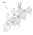
Fig. 2 shows a schematic drawing of an exemplary device for controlling the operation of an internal combustion engine according to the present disclosure; -
Fig. 3 shows a schematic drawing of a retracted position of the exemplary cam follower assembly; -
Fig. 4 shows a schematic drawing of an intermediate position of the exemplary cam follower assembly; -
Fig. 5 shows a schematic drawing of an extended position of an exemplary cam follower assembly; -
Fig. 6 shows a table representing exemplary actuation timings according to the present disclosure; -
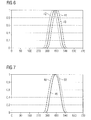
Fig. 7 shows another table representing exemplary actuation timings according to the present disclosure; and -
Fig. 8 shows yet another table representing exemplary actuation timings according to the present disclosure. - The following is a detailed description of exemplary embodiments of the present disclosure. The exemplary embodiments described therein and illustrated in the drawings are intended to teach the principles of the present disclosure, enabling those of ordinary skill in the art to implement and use the present disclosure in many different environments and for many different applications. Therefore, the exemplary embodiments are not intended to be, and should not be considered as, a limiting description of the scope of patent protection. Rather, the scope of patent protection shall be defined by the appended claims.
- The present disclosure is based in part on the realization that hydraulic circuits can be introduced in the field FCT. Said hydraulic circuits may allow increasing a degree of control over actuation timing of components operated by a camshaft such as inlet valves, outlet valves, gas valves, and fuel pumps. Additionally, hydraulic circuits may be implemented in FCT such that individual control of components operated by the same camshaft is facilitated. Moreover, hydraulic circuits may be implemented in FCT to provide a continuous control range to control components.
- Alteratively to provide a hydraulic actuator, a pneumatic actuator being part of a pneumatic circuit, or an electrical actuator being part of an electrical circuit may be provided.
- Accordingly, a cam follower assembly is disclosed which utilizes an actuator to facilitate a change in the actuation timing of a component operated by a cam follower of the cam follower assembly via a displacement of the cam follower relative to the camshaft. As noted above, the actuator may be embodied as hydraulic actuator, pneumatic actuator, or electrical actuator.
- According to
Fig. 1 , a not illustrated internal combustion engine which may be charged via an exhaust gas turbocharger (not shown), is provided, including a camshaft 10 (shown only in part). Camshaft 10 is provided with at least onecam 12 which may be formed integrally withcamshaft 10. Camshaft 10 is rotatably supported and rotatable about a camshaft axis A. Additionally,cam shaft 10 may comprise further cams (not shown) such thatcam shaft 12 is provided with a plurality of cams. - Said internal combustion
engine comprising camshaft 10 may include features not shown, such as air systems, cooling systems, peripheries, drivetrain components, etc. Furthermore, the internal combustion engine may be of any size, with any number of cylinders, and in any configuration (for example, "V," in-line, radial, etc.). Additionally, internal combustion engine may be used to power any machine or other device, including, but not limited to, locomotive applications, on-highway trucks or vehicles, off-highway trucks or machines, earth moving equipment, generators, aerospace applications, marine applications, offshore applications, pumps, stationary equipment, or other engine powered applications. Internal combustion engine may be powered with any fuel including, but not limited to, diesel, gasoline, and/or gaseous fuels. For example, said internal combustion engine may be a dual fuel engine capable to run on a liquid fuel and/or a gaseous fuel, or may be an engine capable to run on various liquid fuels such as diesel and heavy fuel oil. - Cam 12 is adapted to operate a component of the internal combustion engine via a
cam follower assembly 14 and anoperating lifter 16. As is described in greater detail later on, the component may be, for example, an inlet valve, an outlet valve, a gas valve or a fuel pump. -
Cam follower assembly 14 for controlling the operation of the internal combustion engine comprises acam follower 18, a cam follower support 20, and anactuator 22. Camfollower 18 is configured to followcam 12 by tracing the stroke ofcam 12 via, for example, aroll 24 supported thereon and transmitting the same to the component via theoperating lifter 16 supported oncam follower 18 to control the component. - To enable pivoting of
cam follower assembly 14,cam follower support 20 is pivotably supported via, for example, asupport shaft 23 such thatcam follower support 20 is pivotable about a pivot axis B which is spaced apart from camshaft axis A, for example, parallely arranged spaced apart from camshaft axis A. -
Cam follower support 20 supportscam follower 18 via, for example, at least one guiding pin, two of which are shown in the embodiment shown inFig. 1 and are referenced withreference numerals pins cam follower 18 can be guided during displacement caused byactuator 22. Guidingpins follower 18, and may be slideable within guiding pin recesses (not shown) withincam follower 18 or cam follower support 20, respectively. In the shown embodiment, guidingpins pins cam follower assembly 14 may not comprise any guiding pin, and support ofcam follower 18 may be realized viaactuator 22. - For facilitating a displacement of
cam follower 18 towards or away fromcam follower support 20,actuator 22 is provided which is interposed betweencam follower 18 andcam follower support 20 and configured to displacecam follower 18 in a direction perpendicular to camshaft axis A to change an actuation timing of a component operated by an operating lifter supported bycam follower 18tracing cam 12 ofcamshaft 10 during rotation ofcamshaft 10. Perpendicular as used herein may refer to substantially perpendicular including those degree values around 90° which still facilitate the above mentioned varying of actuation time by displacement ofcam follower 18.Actuator 22 may be embodied as hydraulic actuator, pneumatic actuator, or electrical actuator. The following description focuses on the embodiment including the hydraulic actuator, however, one skilled in the art will appreciate that pneumatic and electrical actuators may be used asactuator 22 as well. -
Hydraulic actuator 22 may be, for example, a double acting hydraulic cylinder or a single acting hydraulic cylinder with spring-return. - For example, in an embodiment in which
hydraulic actuator 22 is configured as a single acting cylinder,hydraulic actuator 22 may comprise a fluid chamber (not shown) arranged withincam follower 18 and connected to ahydraulic feed line 30. By allowing flow of a hydraulic fluid throughvalve 32 and supplying a hydraulic fluid to said fluid chamber, a piston can be displaced which in turn displacescam follower 18 with respect tocam follower support 20, and, thereby, also with respect tocamshaft 10. The fluid chamber may be further connected to ahydraulic bleed line 34 provided with avalve 36 to draw the hydraulic fluid. A spring-return may be provided to bias the piston ofhydraulic actuator 22. Alternatively, the fluid chamber may be provided withincam follower support 20. - In another example, in which
hydraulic actuator 22 is configured as double acting hydraulic actuator, movement of a piston may be caused between two fluid chambers selectively supplied with hydraulic fluid. In case one chamber is supplied with hydraulic fluid, hydraulic fluid from the other fluid chamber may be allowed to flow out of the other fluid chamber by opening of a bleed valve, and vice versa. Both fluid chambers may be arranged withincam follower 18, orcam follower support 20. Alternatively, one fluid chamber may be provided incam follower 18, and the other fluid chamber may be provided incam follower support 20. - Turning to
Fig. 2 , adevice 38 for controlling the operation of an internal combustion engine is shown. It is noted thatdevice 38 is exemplary only to describe various applications ofcam follower assembly 14. Therefore, similar components toFig. 1 , which now may have a specific task or function, are referenced with the same reference numeral as generally referred to inFig. 1 - In the shown embodiment,
camshaft 10 is provided with threecams inlet cam 12, outlet cam 12', and pumpcam 12". -
Inlet cam 12 is adapted to operate an inlet valve that is arranged in an inlet of a combustion chamber of a cylinder of the internal combustion engine and operated via an inletcam follower assembly 14 and an inletvalve operating lifter 16. Outlet cam 12' is adapted to operate an outlet valve arranged in an outlet of a combustion chamber of a cylinder of the internal combustion engine via an outlet cam follower assembly 14' and an outlet valve operating lifter 16'.Pump cam 12" is adapted to operate a pump piston arranged in an injection pump via a pumpcam follower assembly 14" and a fuelpump operating lifter 16". - Inlet
cam follower support 20, outlet cam follower support 22', and pumpcam follower support 22" are each individually pivotably supported byrespective support shafts 23 and pivotable about respective pivot axes B. Alternatively, the cam follower supports of each cam follower assembly may be pivotably supported by one support shaft rotatable about a pivot axis, or a sub group of the plurality of cam follower supports may be pivotably supported by one support shaft rotatable about a pivot axis. - Referring to
Figs. 3 to 5 , some possible displacement positions ofcam follower assembly 14 are shown. Specifically,Fig. 3 depicts a retracted position,Fig. 4 an intermediate position, andFig. 5 an extended position ofcam follower assembly 14. Due to the continuous working principle ofhydraulic actuator 22,cam follower 18 can be continuously displaced between a fully retracted position and a fully extended position. - For example, the fully retracted position may be spaced apart from the fully extended position within a range from 2 mm to 40 mm which may depend, for example, on the engine type and size.
- In some embodiments,
hydraulic actuator 22 may be configured to movecam follower 18 with a translational speed corresponding to a rotational speed ofcamshaft 10 during operation. Specifically,hydraulic actuator 22 may be configured to movecam follower 18 with a translational speed corresponding substantially to a circumferential speed of a tip ofcam 12 of rotatingcamshaft 10. - In the following, functionality of
cam follower assembly 14 is described with reference toFigs. 1 to 9 and with specific reference toactuator 22 being embodied as hydraulic actuator. As noted above,actuator 22 may be alternatively embodied as pneumatic actuator or electrical actuator. - The exemplary disclosed
cam follower assembly 14 can be used in multiple ways to increase a degree of control over the internal combustion engine. Specifically, a method for controlling the operation of an internal combustion comprises providing acam follower assembly 14 as exemplary disclosed herein, androtating camshaft 10 about camshaft axis A during operation of internal combustion engine. Additionally, the actuation time of a component such as, for example, a valve or fuel pump, which is operated by operatinglifter 16 supported bycam follower 18 can be varied by displacingcam follower 18 in a direction perpendicular to camshaft axis A viahydraulic actuator 22. - A first possibility of using
cam follower assembly 14 to change the actuation time of a component is depicted inFig. 6 which shows a table. Said table, as well as the tables shown inFigs. 7 and8 , includes an axis of abscissa which indicates a crank angle between 0° and 720°, and an axis of ordinate which indicates a normalized lift between thevalues operating lifter 16 caused bycam follower 18 which converts the rotational movement ofcamshaft 10 in a translatory movement. For example, the lift may refer to a valve lift of an inlet or outlet valve, in which a value of 0 means that the valve is fully closed, and a value of 1 means that the valve is fully opened. - In particular, three exemplary curves are depicted in
Fig. 6 . A first curve 40 (drawn as solid curve) indicates a lift depending on a crank angle for an intermediate position ofcam follower assembly 14, for example, as illustrated inFig. 4 . If the position ofcam follower 18 relative to camshaft 10 is changed by displacement viahydraulic actuator 22, thecurve 40 can be shifted. For example, in an extended position ofhydraulic actuator 22 compared to the position ofhydraulic actuator 22 leading tocurve 40,cam follower 18 may be lifted bycam 12 earlier compared tocurve 40, resulting in a curve 42 (drawn as dotted curve). In other words, actuation time of a component such as an inlet valve, outlet valve or a fuel pump is brought forward (advanced). For example, in the shown configuration,hydraulic actuator 22 is extended to displacecam follower 18 relative tocamshaft 10. - In a similar manner, in a retracted position of
hydraulic actuator 22 compared to the position ofhydraulic actuator 22 resulting incurves cam follower 18 may be lifted bycam 12 later than tocurves hydraulic actuator 22 is retracted to displacecam follower 18 relative tocamshaft 10. In other words, actuation time of a component such as an inlet valve, outlet valve or a fuel pump is postponed (delayed) by displacingcam follower 18 viahydraulic actuator 22 in a direction perpendicular to camshaft axis A. - Naturally, the curves of extended and retracted positions of
cam follower assembly 14 may be exchanged depending on the location ofcam follower support 20 relative tocamshaft 10. - Another possibility of using
cam follower assembly 14 to change the actuation time of a component is depicted inFigs. 7 and8 . - In
Fig. 7 , an exemplary curve 46 (drawn as solid line) is shown which illustrates an operation without movingcam follower 18 whilecamshaft 10 rotates once. In contrast, curves 48 (drawn as dashed curve) and 50 (drawn as dotted curve) result from a movement ofcam follower 18 whilecamshaft 10 rotates once. Similarly inFig. 8 ,exemplary curve 52 illustrates an operation without movingcam follower 18 whilecamshaft 10 rotates once, curves 54 (drawn as dashed curve) and 56 (drawn as dotted curve) result from a movement ofcam follower 18 whilecamshaft 10 rotates once. - Specifically,
curve 48 includes an actuation start time which is brought forward compared to an actuation start time ofcurve 46, an extended full actuation at a lift value of 1.0 compared to a full actuation at a lift value of 1.0 ofcurve 46, and the same actuation end time compared tocurve 46. In contrast,curve 50 includes the same actuation start time ascurve 46, an extended full actuation at a lift value of 1.0 compared tocurve 46, and a postponed actuation end time compared tocurve 46. As can be clearly seen, curves 48 and 50 both have an extended actuation time span, in which a lift value is unequal to a value of 0.0, compared tocurve 46. - For example, dashed
curve 48 may result from the following operation ofcam follower assembly 14.Cam follower 18 may be moved to bring an actuation start time of a component forward duringcam 12 is not in contact withroll 24. During the time in which the component is actuated until a lift value of 1.0,cam follower 18 maintains (holds) its position. During full actuation at a lift value of 1.0,cam follower 18 is moved in direction ofcam 12 to postpone an actuation end time. As the actuation end times ofcurves cam follower 18 ofcurve 48 is moved to the specific position in whichcam follower 18 ofcurve 48 is positioned during end actuation time. - Turning to
Fig. 8 ,curve 54 includes an actuation start time which is brought forward compared to an actuation start time ofcurve 52, an extended full actuation at a lift value of 1.0 compared to a full actuation at a lift value of 1.0 ofcurve 52, and a postponed actuation end time compared tocurve 52. In contrast,curve 54 includes a postponed actuation start time compared tocurve 52, a shortened full actuation at a lift value of 1.0 compared tocurve 52, and an actuation end time which is brought forward compared to an actuation end time ofcurve 52. As can be clearly seen,curve 54 has an extended actuation time span, in which a lift value is unequal to a value of 0.0, compared tocurve 52, whereascurve 56 has a shortened actuation time span compared tocurve 52. - For example, dotted
curve 56 may result from the following operation ofcam follower assembly 14.Cam follower 18 may be moved to postpone an actuation start time of a component duringcam 12 is not in contact withroll 24. During the time in which the component is actuated until a lift value of 1.0,cam follower 18 maintains (holds) its position. During full actuation at a lift value of 1.0,cam follower 18 is moved in a direction opposing rotatingcam 12 to bring an actuation end time forward to shorten an actuation time span. - It is noted that, as exemplary described in connection with
Figs. 7 and8 , extending an actuation time span can be achieved by movingcam follower 18 in a direction of rotatingcam 12 whilecam 12 is in contact withroll 24. Analogous, shortening an actuation time span can be achieved by movingcam follower 18 in a direction opposing rotatingcam 12 whilecam 12 is in contact withroll 24. In other words, extending or shortening the actuation time span can be achieved by movingcam follower 18 with or againstrotating camshaft 10 in the direction perpendicular to camshaft axis A. - Likewise, extending a time span of no actuation can be achieved by moving
cam follower 18 in a direction opposing rotatingcam 12 whilecam 12 is not in contact withroll 24. Analogous, shortening a time span of no actuation can be achieved by movingcam follower 18 in direction of rotatingcam 12 whilecam 12 is not in contact withroll 24. - By controlling cam follower assembly according to any of the above described ways, for example, valve openings and closing of inlet and outlet valves as well as injection timings of fuel pumps may be adjusted depending on various parameters including, but not limited to, engine load, fuel type, engine speed, and environmental influences such as temperature, height and humidity.
-
Cam follower assembly 14 as exemplary disclosed herein may facilitate a continuous control within a control range over components asactuator 22 can displacecam follower 18 to any desired position between a fully extended position and a fully retracted position. Moreover, individualcam follower assemblies 14 may be individually controlled viaindividual actuators 22. - Although the preferred embodiments of this invention have been described herein, improvements and modifications may be incorporated without departing from the scope of the following claims.
Claims (15)
- A cam follower assembly (14) for controlling the operation of an internal combustion engine comprising a camshaft (10) rotatable about a camshaft axis (A), the camshaft (10) being provided with at least one cam (12), the cam follower assembly (14) comprising:a cam follower (18) configured to follow one cam (12);a cam follower support (20) pivotable about a pivot axis (B) spaced apart from the camshaft axis (A), the cam follower support (20) supporting the cam follower (18); andan actuator (22) interposed between the cam follower (18) and the cam follower support (20) and configured to displace the cam follower (18) in a direction perpendicular to the camshaft axis (A).
- The cam follower assembly (14) of claim 1, further comprising at least one guiding pin (26, 28) interposed between the cam follower (18) and the cam follower support (20).
- The cam follower assembly (14) of claim 1 or 2, wherein the actuator (22) is configured as a double acting hydraulic cylinder, or a single acting hydraulic cylinder with spring-return.
- The cam follower assembly (14) of claim 1 or 2, wherein the actuator (22) is configured as an electrical actuator, or a pneumatic actuator.
- The cam follower assembly (14) of any one of the preceding claims, wherein the cam follower (18) is continuously displaceable via the actuator (22) between an extended position and a retracted position.
- The cam follower assembly (14) of any one of the preceding claims, wherein the actuator (22) is configured to move the cam follower (18) with a translational speed corresponding substantially to a rotational speed of the camshaft (10) during operation.
- The cam follower assembly (14) of any one of the preceding claims, wherein the actuator (22) is configured to displace the cam follower (18) between an extended position and a retracted position, the retracted position being spaced apart from the extended position within a range from 2 mm to 40 mm.
- The cam follower assembly (14) of any one of the preceding claims, wherein the cam follower (18) is configured to support a valve operating lifter (16) for controlling the opening and closing of a valve.
- The cam follower assembly (14) of claim 8, wherein the valve controlled by the cam follower (18) is configured as an inlet valve, an outlet valve, or a gas valve.
- The cam follower assembly of any one of claims 1 to 7, wherein the cam follower (18) is configured to support a fuel pump operating lifter (16") for controlling the injection timing of a fuel pump.
- A device (38) for controlling the operation of an internal combustion engine comprising a camshaft (10) rotatable about a camshaft axis (A), the camshaft (10) being provided with a plurality of cams (12), the device (38) comprising a plurality of cam follower assemblies (14) according to any one of claims 1 to 10, each cam follower (18) of the plurality of cam follower assemblies (14) following one of the plurality of cams (12).
- The device (38) of claim 11, wherein
the cam follower supports (20) of each cam follower assembly (14) are pivotably supported by a support shaft (23) rotatable about a pivot axis (B), or
the cam follower supports (20) of each cam follower assembly (14) are individually pivotably supported by individual support shafts (23) rotatable about pivot axes (B). - A method for controlling the operation of an internal combustion engine comprising a camshaft (10) rotatable about a camshaft axis (A), the camshaft (10) being provided with at least one cam (12), comprising:providing a cam follower assembly (14) according to any one of claims 1 to 10;rotating the camshaft (10) about the camshaft axis (A);changing the actuation time of a component operated by an operating lifter (16) supported by the cam follower (18) by displacing the cam follower (18) in a direction perpendicular to the camshaft axis (A) via the actuator (22).
- The method of claim 13, wherein changing the actuation time of the component comprises advancing or delaying the actuation time by displacing the cam follower (18) in the direction perpendicular to the camshaft axis (A).
- The method of claim 13 or 14, wherein changing the actuation time of the component comprises extending or shortening the actuation time span by moving the cam follower (18) with or against the rotating camshaft (10) in the direction perpendicular to the camshaft axis (A).
Priority Applications (3)
| Application Number | Priority Date | Filing Date | Title |
|---|---|---|---|
| EP13167689.2A EP2803829A1 (en) | 2013-05-14 | 2013-05-14 | Flexible cam follower |
| KR1020140055371A KR102223439B1 (en) | 2013-05-14 | 2014-05-09 | Flexible cam technology |
| CN201410201253.5A CN104153835B (en) | 2013-05-14 | 2014-05-13 | Flexible cam technology |
Applications Claiming Priority (1)
| Application Number | Priority Date | Filing Date | Title |
|---|---|---|---|
| EP13167689.2A EP2803829A1 (en) | 2013-05-14 | 2013-05-14 | Flexible cam follower |
Publications (1)
| Publication Number | Publication Date |
|---|---|
| EP2803829A1 true EP2803829A1 (en) | 2014-11-19 |
Family
ID=48463758
Family Applications (1)
| Application Number | Title | Priority Date | Filing Date |
|---|---|---|---|
| EP13167689.2A Withdrawn EP2803829A1 (en) | 2013-05-14 | 2013-05-14 | Flexible cam follower |
Country Status (3)
| Country | Link |
|---|---|
| EP (1) | EP2803829A1 (en) |
| KR (1) | KR102223439B1 (en) |
| CN (1) | CN104153835B (en) |
Cited By (1)
| Publication number | Priority date | Publication date | Assignee | Title |
|---|---|---|---|---|
| US11187118B2 (en) | 2019-05-06 | 2021-11-30 | Caterpillar Motoren Gmbh & Co. Kg | Charge changing control device, reciprocating engine and method for operating a charge changing control device |
Citations (5)
| Publication number | Priority date | Publication date | Assignee | Title |
|---|---|---|---|---|
| GB2322412A (en) * | 1997-02-21 | 1998-08-26 | T & N Technology Ltd | Variable timing valve operating mechanism |
| EP1111205A2 (en) * | 1999-12-10 | 2001-06-27 | Yamaha Hatsudoki Kabushiki Kaisha | Valve drive device of an internal combustion engine |
| DE102004057439A1 (en) * | 2004-11-27 | 2006-06-01 | Man B & W Diesel Ag | Valve operating mechanism for gas exchange valve of diesel engine, has non-adjustable oscillating arm that is shifted in direction of base circle of cam at sliding surface over circular arc-shaped upper surface of adjustable oscillating arm |
| EP2101045A2 (en) * | 2008-03-12 | 2009-09-16 | Kawasaki Jukogyo Kabushiki Kaisha | Valve operating system |
| EP2136054A1 (en) | 2008-06-18 | 2009-12-23 | Caterpillar Motoren GmbH & Co. KG | Method and device for controlling the operation of an internal combustion engine |
Family Cites Families (6)
| Publication number | Priority date | Publication date | Assignee | Title |
|---|---|---|---|---|
| JPH03160103A (en) * | 1989-11-16 | 1991-07-10 | Daihatsu Motor Co Ltd | Valve system of internal combustion engine |
| US5572962A (en) * | 1991-12-03 | 1996-11-12 | Motive Holdings Limited | Variable valve lift mechanism for internal combustion engine |
| US5365895A (en) * | 1991-12-03 | 1994-11-22 | Motive Holdings Limited | Variable valve lift mechanism for internal combustion engine |
| JPH07208123A (en) * | 1994-01-25 | 1995-08-08 | Komatsu Ltd | Cam follower lubrication structure |
| CN101858233B (en) * | 2010-04-29 | 2016-04-20 | 朱譞晟 | Comprise full Variable Valve Time method and the mechanism of speed-changing swing mechanism |
| US8776740B2 (en) * | 2011-01-27 | 2014-07-15 | Scuderi Group, Llc | Lost-motion variable valve actuation system with cam phaser |
-
2013
- 2013-05-14 EP EP13167689.2A patent/EP2803829A1/en not_active Withdrawn
-
2014
- 2014-05-09 KR KR1020140055371A patent/KR102223439B1/en active Active
- 2014-05-13 CN CN201410201253.5A patent/CN104153835B/en not_active Expired - Fee Related
Patent Citations (5)
| Publication number | Priority date | Publication date | Assignee | Title |
|---|---|---|---|---|
| GB2322412A (en) * | 1997-02-21 | 1998-08-26 | T & N Technology Ltd | Variable timing valve operating mechanism |
| EP1111205A2 (en) * | 1999-12-10 | 2001-06-27 | Yamaha Hatsudoki Kabushiki Kaisha | Valve drive device of an internal combustion engine |
| DE102004057439A1 (en) * | 2004-11-27 | 2006-06-01 | Man B & W Diesel Ag | Valve operating mechanism for gas exchange valve of diesel engine, has non-adjustable oscillating arm that is shifted in direction of base circle of cam at sliding surface over circular arc-shaped upper surface of adjustable oscillating arm |
| EP2101045A2 (en) * | 2008-03-12 | 2009-09-16 | Kawasaki Jukogyo Kabushiki Kaisha | Valve operating system |
| EP2136054A1 (en) | 2008-06-18 | 2009-12-23 | Caterpillar Motoren GmbH & Co. KG | Method and device for controlling the operation of an internal combustion engine |
Cited By (1)
| Publication number | Priority date | Publication date | Assignee | Title |
|---|---|---|---|---|
| US11187118B2 (en) | 2019-05-06 | 2021-11-30 | Caterpillar Motoren Gmbh & Co. Kg | Charge changing control device, reciprocating engine and method for operating a charge changing control device |
Also Published As
| Publication number | Publication date |
|---|---|
| CN104153835B (en) | 2018-07-31 |
| KR102223439B1 (en) | 2021-03-05 |
| CN104153835A (en) | 2014-11-19 |
| KR20140134608A (en) | 2014-11-24 |
Similar Documents
| Publication | Publication Date | Title |
|---|---|---|
| CN101619663B (en) | Distribution cam mechanism of two-stroke and four-stroke switching internal-combustion engine | |
| WO2009151352A1 (en) | Late miller internal combustion engine | |
| EP2752571B1 (en) | Method and device for controlling the operation of a dual fuel engine | |
| CN1975117A (en) | Two-step rocker arm having roller element cam followers | |
| CN104454178A (en) | Engine braking method | |
| KR101521335B1 (en) | A control arrangement for an inlet valve in a piston engine | |
| EP2677142B1 (en) | Method and device for controlling the operation of dual-fuel engine | |
| US9322302B2 (en) | Operating internal combustion engines | |
| KR102134052B1 (en) | Gas exchange valve arrangement | |
| US20040168660A1 (en) | Apparatus for an internal combustion engine | |
| EP3736429B1 (en) | Charge changing control device, reciprocating engine and method for operating a charge changing control device | |
| KR102223439B1 (en) | Flexible cam technology | |
| US9664074B2 (en) | Variable valve timing device for internal combustion engines utilizing hydraulic valve actuators | |
| GB2543413A (en) | Valve actuating apparatus for an internal combustion engine | |
| US8776739B2 (en) | Internal combustion engine valve actuation and adjustable lift and timing | |
| EP3396127B1 (en) | Continuous variable valve lift system and car | |
| CN107762587B (en) | Actuating mechanism, variable valve lift device, engine and automobile | |
| EP2998553B1 (en) | Internal combustion engine and associated operating method | |
| WO2012048309A1 (en) | Internal combustion engine valve actuation and adjustable lift and timing | |
| US11047269B2 (en) | Valve train device | |
| FI124245B (en) | Hydraulic valve arrangement for using a controlled gas valve in a piston combustion engine in a controlled manner | |
| EP2752561B1 (en) | Method and device for controlling the operation of an internal combustion engine | |
| EP2187052A1 (en) | Power machine | |
| EP2941548B1 (en) | Valve lifting arrangement and method for operating exhaust valve | |
| CN102606253A (en) | Hydraulic type continuously variable valve device of engine |
Legal Events
| Date | Code | Title | Description |
|---|---|---|---|
| PUAI | Public reference made under article 153(3) epc to a published international application that has entered the european phase |
Free format text: ORIGINAL CODE: 0009012 |
|
| 17P | Request for examination filed |
Effective date: 20130514 |
|
| AK | Designated contracting states |
Kind code of ref document: A1 Designated state(s): AL AT BE BG CH CY CZ DE DK EE ES FI FR GB GR HR HU IE IS IT LI LT LU LV MC MK MT NL NO PL PT RO RS SE SI SK SM TR |
|
| AX | Request for extension of the european patent |
Extension state: BA ME |
|
| R17P | Request for examination filed (corrected) |
Effective date: 20150519 |
|
| RBV | Designated contracting states (corrected) |
Designated state(s): AL AT BE BG CH CY CZ DE DK EE ES FI FR GB GR HR HU IE IS IT LI LT LU LV MC MK MT NL NO PL PT RO RS SE SI SK SM TR |
|
| RIC1 | Information provided on ipc code assigned before grant |
Ipc: F01L 13/00 20060101AFI20150625BHEP |
|
| GRAP | Despatch of communication of intention to grant a patent |
Free format text: ORIGINAL CODE: EPIDOSNIGR1 |
|
| INTG | Intention to grant announced |
Effective date: 20150803 |
|
| STAA | Information on the status of an ep patent application or granted ep patent |
Free format text: STATUS: THE APPLICATION IS DEEMED TO BE WITHDRAWN |
|
| 18D | Application deemed to be withdrawn |
Effective date: 20151215 |