EP2803650A1 - Cooling unit, and cooler provided with same - Google Patents
Cooling unit, and cooler provided with same Download PDFInfo
- Publication number
- EP2803650A1 EP2803650A1 EP12862063.0A EP12862063A EP2803650A1 EP 2803650 A1 EP2803650 A1 EP 2803650A1 EP 12862063 A EP12862063 A EP 12862063A EP 2803650 A1 EP2803650 A1 EP 2803650A1
- Authority
- EP
- European Patent Office
- Prior art keywords
- cooling unit
- diffuser
- granular
- cooling
- substances
- Prior art date
- Legal status (The legal status is an assumption and is not a legal conclusion. Google has not performed a legal analysis and makes no representation as to the accuracy of the status listed.)
- Withdrawn
Links
Images


Classifications
-
- F—MECHANICAL ENGINEERING; LIGHTING; HEATING; WEAPONS; BLASTING
- F27—FURNACES; KILNS; OVENS; RETORTS
- F27D—DETAILS OR ACCESSORIES OF FURNACES, KILNS, OVENS OR RETORTS, IN SO FAR AS THEY ARE OF KINDS OCCURRING IN MORE THAN ONE KIND OF FURNACE
- F27D15/00—Handling or treating discharged material; Supports or receiving chambers therefor
- F27D15/02—Cooling
- F27D15/0206—Cooling with means to convey the charge
- F27D15/0213—Cooling with means to convey the charge comprising a cooling grate
-
- F—MECHANICAL ENGINEERING; LIGHTING; HEATING; WEAPONS; BLASTING
- F27—FURNACES; KILNS; OVENS; RETORTS
- F27B—FURNACES, KILNS, OVENS OR RETORTS IN GENERAL; OPEN SINTERING OR LIKE APPARATUS
- F27B7/00—Rotary-drum furnaces, i.e. horizontal or slightly inclined
- F27B7/20—Details, accessories or equipment specially adapted for rotary-drum furnaces
- F27B7/38—Arrangements of cooling devices
-
- F—MECHANICAL ENGINEERING; LIGHTING; HEATING; WEAPONS; BLASTING
- F27—FURNACES; KILNS; OVENS; RETORTS
- F27B—FURNACES, KILNS, OVENS OR RETORTS IN GENERAL; OPEN SINTERING OR LIKE APPARATUS
- F27B7/00—Rotary-drum furnaces, i.e. horizontal or slightly inclined
- F27B7/20—Details, accessories or equipment specially adapted for rotary-drum furnaces
- F27B7/38—Arrangements of cooling devices
- F27B7/383—Cooling devices for the charge
Definitions
- the present invention relates to a cooling unit of a cooler apparatus configured to cool high-temperature granular conveyed substances, such as granular cement clinkers, while conveying the granular conveyed substances.
- a cement plant is provided with a cooler that conveys high-temperature cement clinkers, produced through preheating, calcinating, and sintering, while cooling the cement clinkers.
- the cooler is a cooler described in PTL 1.
- the cooler includes a plurality of cooling lattices and is assembled by arranging the cooling lattices in a vertical direction.
- Each of the cooling lattices includes a plurality of V-shaped profiles and is configured such that the V-shaped profiles are spaced apart in mirror symmetry and offset to one another. Leg portions of the adjacent V-shaped profiles are arranged with a gap therebetween, and the gap constitutes a labyrinth through which cooling air flows.
- the high-temperature cement clinkers are placed on the cooling lattices configured as above, and the cement clinkers can be conveyed while being cooled by the supply of the cooling air through the labyrinths.
- the labyrinths are formed at the cooling lattices, and the cooling air is supplied through the labyrinths, so that the cement clinkers are prevented from falling down.
- the labyrinths are formed at the cooling lattices, all the cement clinkers cannot be prevented from falling down, and finely-granular cement clinkers may fall down through the labyrinths.
- a passage area of the labyrinth may be reduced.
- a passage pressure loss of the cooling air increases.
- the passage pressure loss of the cooling grate is preferably about 30% of a layer pressure loss. If the passage pressure loss of the cooling grate becomes higher than about 30% of the layer pressure loss, the electric power consumption uneconomically increases.
- an object of the present invention is to provide a cooling unit capable of uniformly cooling granular substances to be conveyed and also capable of preventing not only large granular substances but also finely-granular substances from falling down, and a cooler apparatus including the cooling unit.
- a cooling unit of the present invention is included in a cooler apparatus configured to cool high-temperature granular conveyed substances while conveying the granular conveyed substances, the cooling unit including: a supporting member including a bottom plate and configured to support the granular conveyed substances via a dead layer, the dead layer being formed by depositing on the bottom plate granular embedded substances lower in temperature than the granular conveyed substances; and diffuser tubes provided at such positions as to be embedded in the dead layer and configured to discharge cooling air to the dead layer.
- the diffuser tubes through which the cooling air is supplied are provided separately from the bottom plate, it becomes unnecessary to configure a labyrinth, through which the cooling air is supplied, on the bottom plate. With this, the granular substances can be prevented from falling from the bottom plate.
- the cooling air discharged from the diffuser tubes can be supplied through the dead layer to the granular conveyed substances.
- an appropriate passage pressure loss can be given to the cooling air, and appropriate heat exchange can be performed.
- the granular conveyed substances can be cooled uniformly.
- the diffuser tubes can be embedded in the dead layer constituted by the low-temperature granular embedded substances provided on the bottom plate, the diffuser tubes do not directly contact the high-temperature granular conveyed substances. Therefore, the diffuser tubes can be prevented from being damaged by heat and being worn away by the conveyance of the granular conveyed substances.
- each of the diffuser tubes be arranged parallel to a conveying direction in which the granular conveyed substances are conveyed and include a plurality of diffuser openings through which the cooling air is discharged; and the plurality of diffuser openings be arranged on each of the diffuser tubes so as to be spaced apart from one another in the conveying direction.
- the diffuser tubes extend in the conveying direction, and the diffuser openings are arranged so as to be spaced apart from one another in the conveying direction. Therefore, the granular conveyed substances can be uniformly cooled in the cooler apparatus configured to convey the granular conveyed substances while repeating the movement and stop of the granular conveyed substances.
- the cooling air is supplied through the plurality of diffuser openings. Therefore, by appropriately setting the opening areas of the diffuser openings, the number of diffuser openings, and the positions of the diffuser openings, the heat exchange between the cooling air and the high-temperature cement clinkers can be performed appropriately.
- the diffuser openings be open downward.
- the granular embedded substances can be prevented from getting into the diffuser tubes through the diffuser openings.
- the plurality of diffuser tubes and headers which couple the plurality of diffuser tubes to one another and through which the cooling air is supplied to the diffuser tubes be provided at such positions as to be embedded in the dead layer; and the headers be arranged so as to extend in a direction orthogonal to the conveying direction.
- the cooling air can be supplied to the plurality of diffuser tubes at once by the headers.
- the supporting member include walls standing on an outer peripheral edge portion of the bottom plate and be configured in a box shape.
- the granular embedded substances can be prevented from falling down from not only the bottom side but also front, rear, left, and right sides.
- a cooler apparatus of the present invention includes a plurality of cooling unit trains each configured such that the above cooling units are arranged in a row in the conveying direction, wherein the plurality of cooling unit trains are arranged in parallel with one another in a direction orthogonal to the conveying direction.
- the cooler apparatus having the above functions can be realized.
- the present invention can uniformly cool granular substances to be conveyed and prevent not only large granular substances but also finely-granular substances from falling down.
- a cooling unit 1 according to an embodiment of the present invention and a cooler apparatus 2 including the cooling unit 1 will be explained in reference to the above-described drawings.
- the concept of directions, such as upper, lower, left, right, front, and rear directions, in the embodiment is used for convenience of explanation and does not indicate that the arrangements, directions, and the like of components of the cooling unit 1 and the cooler apparatus 2 are limited to the directions.
- Each of the cooling unit 1 and the cooler apparatus 2 explained below is just one embodiment of the present invention, and the present invention is not limited to the embodiment. Additions, deletions, and modifications may be made within the scope of the present invention.
- Cement is produced through a raw material grinding step of grinding cement raw meal containing limestone, clay, silica stone, iron, and the like, a pyroprocessing step of firing the ground cement raw meal, and a finishing step that is the last step. These three steps are performed at a cement plant. In the pyroprocessing step that is one of these three steps, the ground cement raw meal is fired and cooled, and thus, granular cement clinkers are produced.
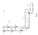
- Fig. 1 shows a pyroprocessing facility 3 of the cement plant, and the pyroprocessing facility 3 being a portion where the pyroprocessing step in cement manufacturing is performed. The pyroprocessing facility 3 performs preheating, calcinating, and sintering of the cement raw meal ground in the raw material grinding step and cools the granular cement clinkers that are high in temperature by the sintering.
- the pyroprocessing facility 3 includes a preheater 4, and the preheater 4 is constituted by a plurality of cyclones 5.
- the cyclones 5 are arranged in an upper-lower direction so as to be provided in a stepped manner. Each cyclone 5 causes exhaust gas therein to flow upward to the cyclone 5 at an upper stage (see broken line arrows in Fig. 1 ), separates the put cement raw meal from one another by rotational flow, and puts the cement raw meal into the cyclone 5 at a lower stage (see solid line arrows in Fig. 1 ).
- the cyclone 5 located immediately above the cyclone 5 at a lowermost stage puts the cement raw meal into a precalciner 6.
- the precalciner 6 includes a burner. By heat of the burner and heat of below-described exhaust gas, the precalciner 6 performs a reaction (that is, a calcination reaction) by which carbon dioxide is separated from the put cement raw meal.
- the cement raw meal subjected to the calcination reaction in the precalciner 6 is introduced to the cyclone 5 at the lowermost stage as described below, and the cement raw meal in this cyclone 5 is then supplied to a rotary kiln 7.
- the rotary kiln 7 is formed in a horizontally long cylindrical shape having several tens of meters or longer.
- the rotary kiln 7 is arranged so as to be slightly inclined downward from an inlet located at the cyclone 5 side toward an outlet located at a tip end side. Therefore, by rotating the rotary kiln 7 about an axis, the cement raw meal at the inlet side is conveyed toward the outlet side.
- a combustion device 8 is provided at the outlet of the rotary kiln 7. The combustion device 8 generates high-temperature flame to sinter the cement raw meal.
- the combustion device 8 ejects a high-temperature combustion gas toward the inlet side, and the combustion gas ejected from the combustion device 8 flows in the rotary kiln 7 toward the inlet while sintering the cement raw meal.
- the combustion gas that is high-temperature exhaust gas flows as jet flow upward through a lower end of the precalciner 6 in the precalciner 6 (see a broken line arrow in Fig. 1 ) to cause the cement raw meal, put in the precalciner 6, to flow upward.
- the cement raw meal is heated by the exhaust gas and the burner up to about 900°C, that is, is subjected to the calcinating.
- the flown cement raw meal flows into the cyclone 5 at the lowermost stage together with the exhaust gas, and the flown exhaust gas and cement raw meal are separated from each other in the cyclone 5 at the lowermost stage.
- the separated cement raw meal is supplied to the rotary kiln 7, and the separated exhaust gas flows upward to the cyclone 5 located immediately above the cyclone 5 at the lowermost stage.
- the flown exhaust gas performs heat exchange with the cement raw meal in each cyclone 5 to heat the cement raw meal.
- the exhaust gas is separated from the cement raw meal again.
- the separated exhaust gas flows upward to the cyclone 5 located above to repeat the heat exchange.
- the exhaust gas is discharged to the atmosphere through the cyclone 5 at an uppermost stage.
- the cement raw meal is put through the vicinity of the cyclone 5 at the uppermost stage, is adequately subjected to preheating while performing the heat exchange with the exhaust gas, moves down to the cyclone 5 located immediately above the cyclone 5 at the lowermost stage, and is then put into the precalciner 6.
- the cement raw meal is subjected to the calcinating by the burner and the high-temperature gas.
- the cement raw meal is introduced to the cyclone 5 at the lowermost stage.
- the cement raw meal is separated from the exhaust gas in the cyclone 5 at the lowermost stage to be supplied to the rotary kiln 7.
- the supplied cement raw meal is conveyed to the outlet side while being subjected to the sintering in the rotary kiln 7.
- the cement clinkers are shaped.
- the cooler apparatus 2 is provided at the outlet of the rotary kiln 7, and the shaped cement clinkers are discharged from the outlet of the rotary kiln 7 to the cooler apparatus 2.
- the cooler apparatus 2 cools the cement clinkers (high-temperature granular conveyed substances), discharged from the rotary kiln 7, while conveying the cement clinkers in a predetermined conveying direction.
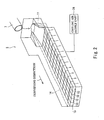
- the cooler apparatus 2 includes a fixed inclined grate 11 located immediately under the outlet of the rotary kiln 7.
- the fixed inclined grate 11 is inclined downward from the outlet side of the rotary kiln 7 toward the conveying direction.
- the granular cement clinkers discharged from the outlet of the rotary kiln 7 roll down on the fixed inclined grate 11 in the conveying direction.
- a plurality of cooling unit trains 13 are provided at a conveying-direction tip end portion of the fixed inclined grate 11.
- the cement clinkers are deposited on the plurality of cooling unit trains 13 to form a clinker layer 14.
- the cooling unit trains 13 are structures each extending in the conveying direction.
- the cooling unit trains 13 are arranged in parallel with one another in a crosswise direction (hereinafter referred to as an "orthogonal direction") orthogonal to the conveying direction so as to be adjacent to one another and not to form a gap between the adjacent cooling unit trains 13. Portions each between the cooling unit trains 13 are sealed to prevent the cement clinkers from falling down.
- the clinker layer 14 (see a chain double-dashed line in Fig. 2 ) is placed on the plurality of cooling unit trains 13, arranged in parallel with one another and sealed without the formation of the gaps, so as to entirely cover the plurality of cooling unit trains 13.
- the plurality of cooling unit trains 13 convey the clinker layer 14 in the conveying direction while cooling the clinker layer 14.
- the granular cement clinkers are conveyed while the movement and stop of the clinker layer 14 are repeated on the cooling unit trains 13.
- Examples of a specific conveying method include: a method of causing all the cooling unit trains 13 to move forward and then causing the cooling unit trains 13 to move backward in such a manner that the cooling unit trains 13 not adjacent to one another are moved backward, and this is performed plural times; and a method of providing a crossbar extending in the orthogonal direction at an upper position of the cooling unit trains 13 and causing the crossbar to move in the conveying direction to transfer the clinker layer 14 in the conveying direction.
- Each of the cooling unit trains 13 configured as above includes a plurality of cooling units 1 and is configured such that the cooling units 1 are arranged in a row in the conveying direction.
- the cooling unit 1 includes a box-shaped casing 21 having a substantially rectangular parallelepiped shape.
- the casing 21 includes a flat bottom plate 21 a at a lower side, and an upper side thereof is open.
- the casing 21 includes four walls 21b to 21e standing on the bottom plate 21 a. Headers 22 each extending in the orthogonal direction are provided at the bottom plate 21 a of the casing 21 configured as above.
- the header 22 has a U-shaped cross section having an opening at a lower side. Opening grooves 21f each extending in the orthogonal direction are respectively formed at positions of the bottom plate 21a, the positions respectively corresponding to the openings of the headers 22.
- Each of the headers 22 extends from the side wall 21 d to the side wall 21 e, and left and right end portions of the header 22 are respectively closed by the side walls 21 d and 21 e.
- a supply passage 22a communicating with a lower space 23 located under the bottom plate 21 a is formed in each header 22.
- a cooling air supply unit 24 (see Fig. 2 ) configured to supply cooling air communicates with the lower space 23 located under the bottom plate 21 a.
- the cooling air is supplied to the supply passages 22a through the lower space located under the bottom plate 21 a.
- a plurality of (in the present embodiment, two) headers 22 configured as above are arranged in the casing 21 so as to be spaced apart from one another in the conveying direction.
- a plurality of diffuser tubes 25 are provided at the headers 22.
- the diffuser tubes 25 are cylindrical members each extending in the conveying direction.
- the diffuser tubes 25 are located so as to be spaced apart from one another in the orthogonal direction.
- the diffuser tubes 25 are provided between the adjacent two headers 22, between the header 22 and the front wall 21b, and between the header 22 and the rear wall 21c.
- Each of the diffuser tubes 25 includes therein a cooling passage 25a, and the cooling passage 25a communicates with the supply passage 22a of the header 22.
- An end portion of the diffuser tube 25 provided at the front wall 21b and an end portion of the diffuser tube 25 provided at the rear wall 21c are respectively closed by the front wall 21b and the rear wall 21c.
- the cooling air is supplied from the headers 22 to the diffuser tubes 25 to flow through the cooling passages 25a.
- Each of the diffuser tubes 25 includes a plurality of diffuser openings 26.
- the diffuser openings 26 are arranged at both sides in the orthogonal direction so as to be separated from each other and are open in a radial direction and an obliquely downward direction.
- the diffuser openings 26 are formed on the diffuser tube 25 so as to be located at substantially regular intervals in the conveying direction.
- the diffuser tube 25 is located upwardly away from the bottom plate 21a by a height h such that the diffuser openings 26 thereof are not covered with the bottom plate 21 a.
- the diffuser tube 25 is provided parallel to the bottom plate 21 a. With this, the cooling air flowing in the diffuser tubes 25 is discharged through the diffuser openings 26 to the outside.
- Cement clinkers having a temperature (for example, a normal temperature from 20 to 60°C) lower than the temperature of the typical cement clinkers discharged from the kiln 7 are put in the casing 21 in which the diffuser tubes 25 are provided.
- the casing 21 is filled with the cement clinkers.
- the cement clinkers are deposited on the bottom plate 21 a to form a dead layer 27 (see a chain double-dashed line in Figs. 3 to 5 ).
- the granular cement clinkers to be conveyed (clinker layer 14; see a chain double-dashed line in Figs. 3 and 4 ) are placed on the dead layer 27, and the bottom plate 21 a supports the granular cement clinkers (clinker layer 14) via the dead layer 27.
- the diffuser tubes 25 are buried in the dead layer 27. That is, the diffuser tubes 25 are embedded in the dead layer 27. Since the diffuser tubes 25 are buried in the dead layer 27 as above, the cooling air discharged from the diffuser tubes 25 can flow through gaps among the cement clinkers of the dead layer 27 to be supplied to the clinker layer 14 located on the dead layer 27. With this, the dead layer 27 can give an appropriate passage pressure loss to the cooling air.
- the passage pressure loss of the dead layer 27 becomes a value corresponding to the height of the dead layer 27 and the positions and sizes of the diffuser openings 26, and the height of the dead layer 27 formed by filling the casing 21 with the cement clinkers is determined in accordance with the side walls 21 d and 21 c of the casing 21. Therefore, the passage pressure loss of the dead layer 27 is set as a value corresponding to the shape of the casing 21 and the positions of the diffuser openings 26.
- the passage pressure loss of the entire cooling unit 1 can be set to a desired value by appropriately setting the height h of the diffuser tube 25, the diameter of each diffuser opening 26, and the number of diffuser openings 26.
- the passage pressure loss By setting the passage pressure loss to the desired value as above, it is possible to prevent uneven flow of the cooling air in the clinker layer 14, the uneven flow being caused by the unevenness of the height of the clinker layer 14 and the bias of the distribution of the particle diameters of the cement clinkers.
- the cooling air of a substantially uniform flow rate can be supplied to the clinker layer 14 to uniformly cool the clinker layer 14. More specifically, by setting the passage pressure loss of the entire cooling unit 1 to an appropriate value, it is possible to reduce a ratio of the pressure loss caused by the unevenness of the height of the clinker layer 14 and the bias of the distribution of the particle diameter of the cement clinkers to the passage pressure loss of the cooling unit 1 and the clinker layer 14. With this, the cooling air flows in a substantially upward direction in the clinker layer 14, and the uneven flow of the cooling air can be prevented. Therefore, the clinker layer 14 can be cooled uniformly.
- the diffuser tubes 25 are embedded in the dead layer 27, the diffuser tubes 25 do not directly contact the clinker layer 14 that is high in temperature and moving. Therefore, the diffuser tubes 25 can be prevented from being damaged by heat and being worn away by the movement of the clinker layer 14.
- the diffuser tubes 25 it becomes unnecessary to form grooves or holes, through which the cooling air is supplied, on the bottom plate 21a as in conventional arts. Therefore, the cement clinkers and the granular cement clinkers are prevented from falling down from the bottom plate 21a. Since the walls 21b to 21e are provided in the conveying direction and the orthogonal direction, the cement clinkers can be prevented from falling down from the casing 21 in the conveying direction and the orthogonal direction (that is, in the front, rear, left, and right directions). Further, since the diffuser openings 26 of the diffuser tubes 25 are open in the obliquely downward direction, the cement clinkers can be prevented from getting into the diffuser tubes 25 through the diffuser openings 26.
- each diffuser opening 26 is formed at such an angle ⁇ that the cement clinkers and the granular cement clinkers do not get into the diffuser tubes 25 through the diffuser openings 26. With this, the diffuser openings 26 and the diffuser tubes 25 can be prevented from being clogged by the cement clinkers, and the cooling air can be supplied through the dead layer 27 to the clinker layer 14 at a desired flow rate.
- the cooler apparatus 2 configured as above, the granular cement clinkers discharged from the rotary kiln 7 are received by the fixed inclined grate 11 to be caused to roll toward the cooling unit trains 13. Then, the cement clinkers are deposited on the cooling unit trains 13 to form the clinker layer 14 on the cooling unit trains 13, and the clinker layer 14 is conveyed in the conveying direction by the above-described method.
- the cooling air supply unit 24 (fan) is operating, and the cooling air is supplied from the cooling air supply unit 24 through the lower space 23 to the supply passages 22a of the headers 22.
- the cooling air in the headers 22 are supplied to the cooling passages 25a of the plurality of diffuser tubes 25 at once to be discharged through the diffuser openings 26 to the outside.
- the cooling air discharged through the diffuser openings 26 flows upward through the gaps among the cement clinkers of the dead layer 27 to reach the clinker layer 14.
- the cooling air performs heat exchange with the granular cement clinkers of the clinker layer 14 to flow through the gaps among the granular cement clinkers of the clinker layer 14 while cooling the granular cement clinkers of the clinker layer 14.
- the cooling air is discharged upward from an upper portion of the clinker layer 14.
- the air discharged upward is high in temperature by the heat exchange with the granular cement clinkers.
- Apart of the high-temperature air is discharged from the cooler apparatus 2 to be directly introduced to the kiln 7 or to be introduced through a discharge pipe 31 to the precalciner 6.
- the granular cement clinkers of the clinker layer 14 are conveyed while being cooled by the cooling unit 1 as above, and the granular cement clinkers are continuously cooled down to a temperature higher than an atmospheric temperature by several tens of degrees.
- the cement clinkers are used as the granular substances forming the dead layer 27.
- heat-resistant granular substances such as metal granular substances or ceramic granular substances, other than the cement clinkers may be used.
- the sizes of the particle diameters of the granular substances to be conveyed and the sizes of the particle diameters of the granular substances forming the dead layer 27 are not limited.
- the outer shapes and arrangement positions of the diffuser tubes 25 are not limited to the above.
- the diffuser tubes 25 may be orthogonal to the conveying direction and may be formed in an accordion shape.
- the bottom plate 21a is a flat plate.
- the bottom plate 21a may be a V-shaped plate projecting downward or upward or an inclined plate inclined in the orthogonal direction or the conveying direction.
Landscapes
- Engineering & Computer Science (AREA)
- Mechanical Engineering (AREA)
- General Engineering & Computer Science (AREA)
- Furnace Details (AREA)
- Curing Cements, Concrete, And Artificial Stone (AREA)
Abstract
Description
- The present invention relates to a cooling unit of a cooler apparatus configured to cool high-temperature granular conveyed substances, such as granular cement clinkers, while conveying the granular conveyed substances.
- A cement plant is provided with a cooler that conveys high-temperature cement clinkers, produced through preheating, calcinating, and sintering, while cooling the cement clinkers. One example of the cooler is a cooler described in
PTL 1. The cooler includes a plurality of cooling lattices and is assembled by arranging the cooling lattices in a vertical direction. Each of the cooling lattices includes a plurality of V-shaped profiles and is configured such that the V-shaped profiles are spaced apart in mirror symmetry and offset to one another. Leg portions of the adjacent V-shaped profiles are arranged with a gap therebetween, and the gap constitutes a labyrinth through which cooling air flows. The high-temperature cement clinkers are placed on the cooling lattices configured as above, and the cement clinkers can be conveyed while being cooled by the supply of the cooling air through the labyrinths. - PTL 1: Japanese Laid-Open Patent Application Publication No.
2007-515365 - In the cooler described in
PTL 1, the labyrinths are formed at the cooling lattices, and the cooling air is supplied through the labyrinths, so that the cement clinkers are prevented from falling down. However, since the labyrinths are formed at the cooling lattices, all the cement clinkers cannot be prevented from falling down, and finely-granular cement clinkers may fall down through the labyrinths. To prevent the finely-granular cement clinkers from falling down, a passage area of the labyrinth may be reduced. However, if the passage area of the labyrinth is reduced, a passage pressure loss of the cooling air increases. The passage pressure loss of the cooling grate is preferably about 30% of a layer pressure loss. If the passage pressure loss of the cooling grate becomes higher than about 30% of the layer pressure loss, the electric power consumption uneconomically increases. - Here, an object of the present invention is to provide a cooling unit capable of uniformly cooling granular substances to be conveyed and also capable of preventing not only large granular substances but also finely-granular substances from falling down, and a cooler apparatus including the cooling unit.
- A cooling unit of the present invention is included in a cooler apparatus configured to cool high-temperature granular conveyed substances while conveying the granular conveyed substances, the cooling unit including: a supporting member including a bottom plate and configured to support the granular conveyed substances via a dead layer, the dead layer being formed by depositing on the bottom plate granular embedded substances lower in temperature than the granular conveyed substances; and diffuser tubes provided at such positions as to be embedded in the dead layer and configured to discharge cooling air to the dead layer.
- According to the present invention, since the diffuser tubes through which the cooling air is supplied are provided separately from the bottom plate, it becomes unnecessary to configure a labyrinth, through which the cooling air is supplied, on the bottom plate. With this, the granular substances can be prevented from falling from the bottom plate.
- In the present invention, since the diffuser tubes can be embedded in the dead layer, the cooling air discharged from the diffuser tubes can be supplied through the dead layer to the granular conveyed substances. With this, an appropriate passage pressure loss can be given to the cooling air, and appropriate heat exchange can be performed. Thus, the granular conveyed substances can be cooled uniformly.
- Further, in the present invention, since the diffuser tubes can be embedded in the dead layer constituted by the low-temperature granular embedded substances provided on the bottom plate, the diffuser tubes do not directly contact the high-temperature granular conveyed substances. Therefore, the diffuser tubes can be prevented from being damaged by heat and being worn away by the conveyance of the granular conveyed substances.
- In the above invention, it is preferable that: each of the diffuser tubes be arranged parallel to a conveying direction in which the granular conveyed substances are conveyed and include a plurality of diffuser openings through which the cooling air is discharged; and the plurality of diffuser openings be arranged on each of the diffuser tubes so as to be spaced apart from one another in the conveying direction.
- According to the above configuration, the diffuser tubes extend in the conveying direction, and the diffuser openings are arranged so as to be spaced apart from one another in the conveying direction. Therefore, the granular conveyed substances can be uniformly cooled in the cooler apparatus configured to convey the granular conveyed substances while repeating the movement and stop of the granular conveyed substances.
- According to the present invention, the cooling air is supplied through the plurality of diffuser openings. Therefore, by appropriately setting the opening areas of the diffuser openings, the number of diffuser openings, and the positions of the diffuser openings, the heat exchange between the cooling air and the high-temperature cement clinkers can be performed appropriately.
- In the above invention, it is preferable that the diffuser openings be open downward.
- According to the above configuration, the granular embedded substances can be prevented from getting into the diffuser tubes through the diffuser openings.
- In the above invention, it is preferable that: the plurality of diffuser tubes and headers which couple the plurality of diffuser tubes to one another and through which the cooling air is supplied to the diffuser tubes be provided at such positions as to be embedded in the dead layer; and the headers be arranged so as to extend in a direction orthogonal to the conveying direction.
- According to the above configuration, the cooling air can be supplied to the plurality of diffuser tubes at once by the headers.
- In the above invention, it is preferable that the supporting member include walls standing on an outer peripheral edge portion of the bottom plate and be configured in a box shape.
- According to the above configuration, the granular embedded substances can be prevented from falling down from not only the bottom side but also front, rear, left, and right sides.
- A cooler apparatus of the present invention includes a plurality of cooling unit trains each configured such that the above cooling units are arranged in a row in the conveying direction, wherein the plurality of cooling unit trains are arranged in parallel with one another in a direction orthogonal to the conveying direction.
- According to the above configuration, the cooler apparatus having the above functions can be realized.
- The above object, other objects, features, and advantages of the present invention will be made clear by the following detailed explanation of preferred embodiments with reference to the attached drawings.
- The present invention can uniformly cool granular substances to be conveyed and prevent not only large granular substances but also finely-granular substances from falling down.
-
- [
Fig. 1] Fig. 1 is a schematic diagram showing the configuration of a cement plant including a cooler apparatus according to the present invention. - [
Fig. 2] Fig. 2 is a perspective view schematically showing the configuration of the cooler apparatus ofFig. 1 . - [
Fig. 3] Fig. 3 is a front view showing the configuration of a cooling unit included in the cooler apparatus ofFig. 2 . - [
Fig. 4] Fig. 4 is a cross-sectional view taken along line A-A ofFig. 3 and showing the configuration of the cooling unit. - [
Fig. 5] Fig. 5 is an enlarged cross-sectional view of the vicinity of a diffuser tube shown inFig. 4 . - Hereinafter, a
cooling unit 1 according to an embodiment of the present invention and acooler apparatus 2 including thecooling unit 1 will be explained in reference to the above-described drawings. The concept of directions, such as upper, lower, left, right, front, and rear directions, in the embodiment is used for convenience of explanation and does not indicate that the arrangements, directions, and the like of components of thecooling unit 1 and thecooler apparatus 2 are limited to the directions. Each of thecooling unit 1 and thecooler apparatus 2 explained below is just one embodiment of the present invention, and the present invention is not limited to the embodiment. Additions, deletions, and modifications may be made within the scope of the present invention. - Cement is produced through a raw material grinding step of grinding cement raw meal containing limestone, clay, silica stone, iron, and the like, a pyroprocessing step of firing the ground cement raw meal, and a finishing step that is the last step. These three steps are performed at a cement plant. In the pyroprocessing step that is one of these three steps, the ground cement raw meal is fired and cooled, and thus, granular cement clinkers are produced.
Fig. 1 shows a pyroprocessing facility 3 of the cement plant, and the pyroprocessing facility 3 being a portion where the pyroprocessing step in cement manufacturing is performed. The pyroprocessing facility 3 performs preheating, calcinating, and sintering of the cement raw meal ground in the raw material grinding step and cools the granular cement clinkers that are high in temperature by the sintering. - The portion where the pyroprocessing step is performed will be explained in further detail. The pyroprocessing facility 3 includes a preheater 4, and the preheater 4 is constituted by a plurality of
cyclones 5. Thecyclones 5 are arranged in an upper-lower direction so as to be provided in a stepped manner. Eachcyclone 5 causes exhaust gas therein to flow upward to thecyclone 5 at an upper stage (see broken line arrows inFig. 1 ), separates the put cement raw meal from one another by rotational flow, and puts the cement raw meal into thecyclone 5 at a lower stage (see solid line arrows inFig. 1 ). Thecyclone 5 located immediately above thecyclone 5 at a lowermost stage puts the cement raw meal into aprecalciner 6. Theprecalciner 6 includes a burner. By heat of the burner and heat of below-described exhaust gas, theprecalciner 6 performs a reaction (that is, a calcination reaction) by which carbon dioxide is separated from the put cement raw meal. The cement raw meal subjected to the calcination reaction in theprecalciner 6 is introduced to thecyclone 5 at the lowermost stage as described below, and the cement raw meal in thiscyclone 5 is then supplied to arotary kiln 7. - The
rotary kiln 7 is formed in a horizontally long cylindrical shape having several tens of meters or longer. Therotary kiln 7 is arranged so as to be slightly inclined downward from an inlet located at thecyclone 5 side toward an outlet located at a tip end side. Therefore, by rotating therotary kiln 7 about an axis, the cement raw meal at the inlet side is conveyed toward the outlet side. Acombustion device 8 is provided at the outlet of therotary kiln 7. Thecombustion device 8 generates high-temperature flame to sinter the cement raw meal. - The
combustion device 8 ejects a high-temperature combustion gas toward the inlet side, and the combustion gas ejected from thecombustion device 8 flows in therotary kiln 7 toward the inlet while sintering the cement raw meal. The combustion gas that is high-temperature exhaust gas flows as jet flow upward through a lower end of theprecalciner 6 in the precalciner 6 (see a broken line arrow inFig. 1 ) to cause the cement raw meal, put in theprecalciner 6, to flow upward. The cement raw meal is heated by the exhaust gas and the burner up to about 900°C, that is, is subjected to the calcinating. The flown cement raw meal flows into thecyclone 5 at the lowermost stage together with the exhaust gas, and the flown exhaust gas and cement raw meal are separated from each other in thecyclone 5 at the lowermost stage. The separated cement raw meal is supplied to therotary kiln 7, and the separated exhaust gas flows upward to thecyclone 5 located immediately above thecyclone 5 at the lowermost stage. The flown exhaust gas performs heat exchange with the cement raw meal in eachcyclone 5 to heat the cement raw meal. Then, the exhaust gas is separated from the cement raw meal again. The separated exhaust gas flows upward to thecyclone 5 located above to repeat the heat exchange. Then, the exhaust gas is discharged to the atmosphere through thecyclone 5 at an uppermost stage. - In the pyroprocessing facility 3 configured as above, the cement raw meal is put through the vicinity of the
cyclone 5 at the uppermost stage, is adequately subjected to preheating while performing the heat exchange with the exhaust gas, moves down to thecyclone 5 located immediately above thecyclone 5 at the lowermost stage, and is then put into theprecalciner 6. In theprecalciner 6, the cement raw meal is subjected to the calcinating by the burner and the high-temperature gas. Then, the cement raw meal is introduced to thecyclone 5 at the lowermost stage. The cement raw meal is separated from the exhaust gas in thecyclone 5 at the lowermost stage to be supplied to therotary kiln 7. The supplied cement raw meal is conveyed to the outlet side while being subjected to the sintering in therotary kiln 7. Through the preheating, the calcinating, and the sintering, the cement clinkers are shaped. Thecooler apparatus 2 is provided at the outlet of therotary kiln 7, and the shaped cement clinkers are discharged from the outlet of therotary kiln 7 to thecooler apparatus 2. - The
cooler apparatus 2 cools the cement clinkers (high-temperature granular conveyed substances), discharged from therotary kiln 7, while conveying the cement clinkers in a predetermined conveying direction. As shown inFig. 2 , thecooler apparatus 2 includes a fixedinclined grate 11 located immediately under the outlet of therotary kiln 7. The fixedinclined grate 11 is inclined downward from the outlet side of therotary kiln 7 toward the conveying direction. The granular cement clinkers discharged from the outlet of therotary kiln 7 roll down on the fixedinclined grate 11 in the conveying direction. A plurality of cooling unit trains 13 are provided at a conveying-direction tip end portion of the fixedinclined grate 11. The cement clinkers are deposited on the plurality of cooling unit trains 13 to form aclinker layer 14. - The cooling unit trains 13 are structures each extending in the conveying direction. The cooling unit trains 13 are arranged in parallel with one another in a crosswise direction (hereinafter referred to as an "orthogonal direction") orthogonal to the conveying direction so as to be adjacent to one another and not to form a gap between the adjacent cooling unit trains 13. Portions each between the cooling unit trains 13 are sealed to prevent the cement clinkers from falling down. The clinker layer 14 (see a chain double-dashed line in
Fig. 2 ) is placed on the plurality of cooling unit trains 13, arranged in parallel with one another and sealed without the formation of the gaps, so as to entirely cover the plurality of cooling unit trains 13. - The plurality of cooling unit trains 13 convey the
clinker layer 14 in the conveying direction while cooling theclinker layer 14. The granular cement clinkers are conveyed while the movement and stop of theclinker layer 14 are repeated on the cooling unit trains 13. Examples of a specific conveying method include: a method of causing all the cooling unit trains 13 to move forward and then causing the cooling unit trains 13 to move backward in such a manner that the cooling unit trains 13 not adjacent to one another are moved backward, and this is performed plural times; and a method of providing a crossbar extending in the orthogonal direction at an upper position of the cooling unit trains 13 and causing the crossbar to move in the conveying direction to transfer theclinker layer 14 in the conveying direction. The configuration and method of transferring theclinker layer 14 in the conveying direction are not limited to the above, and any configuration and method may be adopted as long as theclinker layer 14 can be transferred in the conveying direction. Each of the cooling unit trains 13 configured as above includes a plurality ofcooling units 1 and is configured such that the coolingunits 1 are arranged in a row in the conveying direction. - As shown in
Figs. 3 and4 , thecooling unit 1 includes a box-shapedcasing 21 having a substantially rectangular parallelepiped shape. Thecasing 21 includes aflat bottom plate 21 a at a lower side, and an upper side thereof is open. Thecasing 21 includes fourwalls 21b to 21e standing on thebottom plate 21 a.Headers 22 each extending in the orthogonal direction are provided at thebottom plate 21 a of thecasing 21 configured as above. - The
header 22 has a U-shaped cross section having an opening at a lower side. Openinggrooves 21f each extending in the orthogonal direction are respectively formed at positions of thebottom plate 21a, the positions respectively corresponding to the openings of theheaders 22. Each of theheaders 22 extends from theside wall 21 d to theside wall 21 e, and left and right end portions of theheader 22 are respectively closed by theside walls supply passage 22a communicating with alower space 23 located under thebottom plate 21 a is formed in eachheader 22. A cooling air supply unit 24 (seeFig. 2 ) configured to supply cooling air communicates with thelower space 23 located under thebottom plate 21 a. The cooling air is supplied to thesupply passages 22a through the lower space located under thebottom plate 21 a. A plurality of (in the present embodiment, two)headers 22 configured as above are arranged in thecasing 21 so as to be spaced apart from one another in the conveying direction. A plurality ofdiffuser tubes 25 are provided at theheaders 22. - The
diffuser tubes 25 are cylindrical members each extending in the conveying direction. Thediffuser tubes 25 are located so as to be spaced apart from one another in the orthogonal direction. Thediffuser tubes 25 are provided between the adjacent twoheaders 22, between theheader 22 and thefront wall 21b, and between theheader 22 and therear wall 21c. Each of thediffuser tubes 25 includes therein acooling passage 25a, and thecooling passage 25a communicates with thesupply passage 22a of theheader 22. An end portion of thediffuser tube 25 provided at thefront wall 21b and an end portion of thediffuser tube 25 provided at therear wall 21c are respectively closed by thefront wall 21b and therear wall 21c. The cooling air is supplied from theheaders 22 to thediffuser tubes 25 to flow through thecooling passages 25a. Each of thediffuser tubes 25 includes a plurality ofdiffuser openings 26. - As shown in
Fig. 5 , in a plane orthogonal to an axis of thediffuser tube 25 and in a lower half plane of thediffuser tube 25, thediffuser openings 26 are arranged at both sides in the orthogonal direction so as to be separated from each other and are open in a radial direction and an obliquely downward direction. Thediffuser openings 26 are formed on thediffuser tube 25 so as to be located at substantially regular intervals in the conveying direction. Thediffuser tube 25 is located upwardly away from thebottom plate 21a by a height h such that thediffuser openings 26 thereof are not covered with thebottom plate 21 a. In addition, thediffuser tube 25 is provided parallel to thebottom plate 21 a. With this, the cooling air flowing in thediffuser tubes 25 is discharged through thediffuser openings 26 to the outside. - Cement clinkers having a temperature (for example, a normal temperature from 20 to 60°C) lower than the temperature of the typical cement clinkers discharged from the
kiln 7 are put in thecasing 21 in which thediffuser tubes 25 are provided. Thecasing 21 is filled with the cement clinkers. With this, the cement clinkers are deposited on thebottom plate 21 a to form a dead layer 27 (see a chain double-dashed line inFigs. 3 to 5 ). The granular cement clinkers to be conveyed (clinker layer 14; see a chain double-dashed line inFigs. 3 and4 ) are placed on thedead layer 27, and thebottom plate 21 a supports the granular cement clinkers (clinker layer 14) via thedead layer 27. - Since the
casing 21 is filled with the cement clinkers, thediffuser tubes 25 are buried in thedead layer 27. That is, thediffuser tubes 25 are embedded in thedead layer 27. Since thediffuser tubes 25 are buried in thedead layer 27 as above, the cooling air discharged from thediffuser tubes 25 can flow through gaps among the cement clinkers of thedead layer 27 to be supplied to theclinker layer 14 located on thedead layer 27. With this, thedead layer 27 can give an appropriate passage pressure loss to the cooling air. - The passage pressure loss of the
dead layer 27 becomes a value corresponding to the height of thedead layer 27 and the positions and sizes of thediffuser openings 26, and the height of thedead layer 27 formed by filling thecasing 21 with the cement clinkers is determined in accordance with theside walls casing 21. Therefore, the passage pressure loss of thedead layer 27 is set as a value corresponding to the shape of thecasing 21 and the positions of thediffuser openings 26. The passage pressure loss of theentire cooling unit 1 can be set to a desired value by appropriately setting the height h of thediffuser tube 25, the diameter of eachdiffuser opening 26, and the number ofdiffuser openings 26. - By setting the passage pressure loss to the desired value as above, it is possible to prevent uneven flow of the cooling air in the
clinker layer 14, the uneven flow being caused by the unevenness of the height of theclinker layer 14 and the bias of the distribution of the particle diameters of the cement clinkers. To be specific, the cooling air of a substantially uniform flow rate can be supplied to theclinker layer 14 to uniformly cool theclinker layer 14. More specifically, by setting the passage pressure loss of theentire cooling unit 1 to an appropriate value, it is possible to reduce a ratio of the pressure loss caused by the unevenness of the height of theclinker layer 14 and the bias of the distribution of the particle diameter of the cement clinkers to the passage pressure loss of thecooling unit 1 and theclinker layer 14. With this, the cooling air flows in a substantially upward direction in theclinker layer 14, and the uneven flow of the cooling air can be prevented. Therefore, theclinker layer 14 can be cooled uniformly. - Since the
diffuser tubes 25 are embedded in thedead layer 27, thediffuser tubes 25 do not directly contact theclinker layer 14 that is high in temperature and moving. Therefore, thediffuser tubes 25 can be prevented from being damaged by heat and being worn away by the movement of theclinker layer 14. - Further, by using the
diffuser tubes 25, it becomes unnecessary to form grooves or holes, through which the cooling air is supplied, on thebottom plate 21a as in conventional arts. Therefore, the cement clinkers and the granular cement clinkers are prevented from falling down from thebottom plate 21a. Since thewalls 21b to 21e are provided in the conveying direction and the orthogonal direction, the cement clinkers can be prevented from falling down from thecasing 21 in the conveying direction and the orthogonal direction (that is, in the front, rear, left, and right directions). Further, since thediffuser openings 26 of thediffuser tubes 25 are open in the obliquely downward direction, the cement clinkers can be prevented from getting into thediffuser tubes 25 through thediffuser openings 26. To be specific, eachdiffuser opening 26 is formed at such an angle θ that the cement clinkers and the granular cement clinkers do not get into thediffuser tubes 25 through thediffuser openings 26. With this, thediffuser openings 26 and thediffuser tubes 25 can be prevented from being clogged by the cement clinkers, and the cooling air can be supplied through thedead layer 27 to theclinker layer 14 at a desired flow rate. - According to the
cooler apparatus 2 configured as above, the granular cement clinkers discharged from therotary kiln 7 are received by the fixedinclined grate 11 to be caused to roll toward the cooling unit trains 13. Then, the cement clinkers are deposited on the cooling unit trains 13 to form theclinker layer 14 on the cooling unit trains 13, and theclinker layer 14 is conveyed in the conveying direction by the above-described method. During the conveyance, the cooling air supply unit 24 (fan) is operating, and the cooling air is supplied from the coolingair supply unit 24 through thelower space 23 to thesupply passages 22a of theheaders 22. The cooling air in theheaders 22 are supplied to thecooling passages 25a of the plurality ofdiffuser tubes 25 at once to be discharged through thediffuser openings 26 to the outside. The cooling air discharged through thediffuser openings 26 flows upward through the gaps among the cement clinkers of thedead layer 27 to reach theclinker layer 14. The cooling air performs heat exchange with the granular cement clinkers of theclinker layer 14 to flow through the gaps among the granular cement clinkers of theclinker layer 14 while cooling the granular cement clinkers of theclinker layer 14. Then, the cooling air is discharged upward from an upper portion of theclinker layer 14. The air discharged upward is high in temperature by the heat exchange with the granular cement clinkers. Apart of the high-temperature air is discharged from thecooler apparatus 2 to be directly introduced to thekiln 7 or to be introduced through adischarge pipe 31 to theprecalciner 6. - According to the
cooler apparatus 2, the granular cement clinkers of theclinker layer 14 are conveyed while being cooled by thecooling unit 1 as above, and the granular cement clinkers are continuously cooled down to a temperature higher than an atmospheric temperature by several tens of degrees. - In the above embodiment, the cement clinkers are used as the granular substances forming the
dead layer 27. However, heat-resistant granular substances, such as metal granular substances or ceramic granular substances, other than the cement clinkers may be used. The sizes of the particle diameters of the granular substances to be conveyed and the sizes of the particle diameters of the granular substances forming thedead layer 27 are not limited. The outer shapes and arrangement positions of thediffuser tubes 25 are not limited to the above. Thediffuser tubes 25 may be orthogonal to the conveying direction and may be formed in an accordion shape. In the above embodiment, thebottom plate 21a is a flat plate. However, thebottom plate 21a may be a V-shaped plate projecting downward or upward or an inclined plate inclined in the orthogonal direction or the conveying direction. - From the foregoing explanation, many modifications and other embodiments of the present invention are obvious to one skilled in the art. Therefore, the foregoing explanation should be interpreted only as an example and is provided for the purpose of teaching the best mode for carrying out the present invention to one skilled in the art. The structures and/or functional details may be substantially modified within the spirit of the present invention.
-
- 1
- cooling unit
- 2
- cooler apparatus
- 13
- cooling unit train
- 14
- clinker layer
- 21
- casing
- 21a
- bottom plate
- 22
- header
- 25
- diffuser tube
- 26
- diffuser opening
- 27
- dead layer
Claims (6)
- A cooling unit of a cooler apparatus configured to cool high-temperature granular conveyed substances while conveying the granular conveyed substances,
the cooling unit comprising:a supporting member including a bottom plate and configured to support the granular conveyed substances via a dead layer, the dead layer being formed by depositing on the bottom plate granular embedded substances lower in temperature than the granular conveyed substances; anddiffuser tubes provided at such positions as to be embedded in the dead layer and configured to discharge cooling air to the dead layer. - The cooling unit according to claim 1, wherein:each of the diffuser tubes is arranged parallel to a conveying direction in which the granular conveyed substances are conveyed and includes a plurality of diffuser openings through which the cooling air is discharged; andthe plurality of diffuser openings are arranged on each of the diffuser tubes so as to be spaced apart from one another in the conveying direction.
- The cooling unit according to claim 2, wherein the diffuser openings are open downward.
- The cooling unit according to claim 3, wherein:the plurality of diffuser tubes and headers which couple the plurality of diffuser tubes to one another and through which the cooling air is supplied to the diffuser tubes are provided at such positions as to be embedded in the dead layer; andthe headers are arranged so as to extend in a direction orthogonal to the conveying direction.
- The cooling unit according to any one of claims 1 to 4, wherein the supporting member includes walls standing on an outer peripheral edge portion of the bottom plate and is configured in a box shape.
- A cooler apparatus comprising a plurality of cooling unit trains each configured such that the cooling units according to any one of claims 1 to 5 are arranged in a row in the conveying direction, wherein
the plurality of cooling unit trains are arranged in parallel with one another in a direction orthogonal to the conveying direction.
Applications Claiming Priority (2)
| Application Number | Priority Date | Filing Date | Title |
|---|---|---|---|
| JP2011283408A JP5977515B2 (en) | 2011-12-26 | 2011-12-26 | Cooling unit and cooler device including the same |
| PCT/JP2012/008292 WO2013099231A1 (en) | 2011-12-26 | 2012-12-26 | Cooling unit, and cooler provided with same |
Publications (2)
| Publication Number | Publication Date |
|---|---|
| EP2803650A1 true EP2803650A1 (en) | 2014-11-19 |
| EP2803650A4 EP2803650A4 (en) | 2015-09-23 |
Family
ID=48696766
Family Applications (1)
| Application Number | Title | Priority Date | Filing Date |
|---|---|---|---|
| EP12862063.0A Withdrawn EP2803650A4 (en) | 2011-12-26 | 2012-12-26 | COOLING DEVICE, AND COOLER EQUIPPED WITH SAME |
Country Status (6)
| Country | Link |
|---|---|
| EP (1) | EP2803650A4 (en) |
| JP (1) | JP5977515B2 (en) |
| CN (1) | CN104010986B (en) |
| MY (1) | MY167914A (en) |
| TW (1) | TWI460145B (en) |
| WO (1) | WO2013099231A1 (en) |
Cited By (1)
| Publication number | Priority date | Publication date | Assignee | Title |
|---|---|---|---|---|
| US20240093941A1 (en) * | 2019-10-14 | 2024-03-21 | Thyssenkrupp Industrial Solutions Ag | Cooler and a method for cooling bulk material |
Families Citing this family (2)
| Publication number | Priority date | Publication date | Assignee | Title |
|---|---|---|---|---|
| CN106482526B (en) * | 2015-08-31 | 2019-07-26 | 川崎重工业株式会社 | The cooling grid of cooling device and the cooling device for having the cooling grid |
| JP6838955B2 (en) * | 2016-12-13 | 2021-03-03 | 川崎重工業株式会社 | Cooler device |
Family Cites Families (11)
| Publication number | Priority date | Publication date | Assignee | Title |
|---|---|---|---|---|
| JPS57166347A (en) * | 1981-03-31 | 1982-10-13 | Ishikawajima Harima Heavy Ind | Cement clinker cooling equipment |
| JPS61101238A (en) * | 1984-10-25 | 1986-05-20 | Mitsubishi Heavy Ind Ltd | Apparatus for heat exchanging between coarse and fine particles |
| DK154692D0 (en) * | 1992-12-23 | 1992-12-23 | Smidth & Co As F L | PROCEDURE AND COOLER FOR COOLING PARTICULATED MATERIAL |
| JPH11248370A (en) * | 1998-02-27 | 1999-09-14 | Babcock Hitachi Kk | Ingot cooling device |
| JP2001048606A (en) * | 1999-08-11 | 2001-02-20 | Ishikawajima Harima Heavy Ind Co Ltd | Cement clinker cooling device |
| EP1475594A1 (en) * | 2003-05-08 | 2004-11-10 | Claudius Peters Technologies GmbH | Process and apparatus to transport bulk material on a grid |
| DE10355822B4 (en) | 2003-11-28 | 2013-06-13 | Khd Humboldt Wedag Gmbh | Bulk cooler for cooling hot chilled goods |
| EA011701B1 (en) * | 2005-05-10 | 2009-04-28 | ФЁНС ТЕКНОЛОДЖИ АпС | Method and apparatus for treating a bed of bulk material |
| WO2009156227A1 (en) * | 2008-06-26 | 2009-12-30 | Flsmidth A/S | Method and cooler for cooling hot particulate material |
| CN101397195A (en) * | 2008-10-24 | 2009-04-01 | 南京西普机电工程有限公司 | Clinker transport mechanism for cement clinker cooling machine |
| CN102032796B (en) * | 2009-09-28 | 2013-12-25 | 高玉宗 | Covering belt cooler |
-
2011
- 2011-12-26 JP JP2011283408A patent/JP5977515B2/en not_active Expired - Fee Related
-
2012
- 2012-12-24 TW TW101149412A patent/TWI460145B/en not_active IP Right Cessation
- 2012-12-26 CN CN201280062901.2A patent/CN104010986B/en not_active Expired - Fee Related
- 2012-12-26 WO PCT/JP2012/008292 patent/WO2013099231A1/en not_active Ceased
- 2012-12-26 MY MYPI2014701737A patent/MY167914A/en unknown
- 2012-12-26 EP EP12862063.0A patent/EP2803650A4/en not_active Withdrawn
Cited By (2)
| Publication number | Priority date | Publication date | Assignee | Title |
|---|---|---|---|---|
| US20240093941A1 (en) * | 2019-10-14 | 2024-03-21 | Thyssenkrupp Industrial Solutions Ag | Cooler and a method for cooling bulk material |
| US12123650B2 (en) * | 2019-10-14 | 2024-10-22 | thyssenkrupp Polysius GmbH | Cooler and a method for cooling bulk material |
Also Published As
| Publication number | Publication date |
|---|---|
| WO2013099231A1 (en) | 2013-07-04 |
| EP2803650A4 (en) | 2015-09-23 |
| MY167914A (en) | 2018-09-27 |
| CN104010986A (en) | 2014-08-27 |
| TWI460145B (en) | 2014-11-11 |
| JP5977515B2 (en) | 2016-08-24 |
| TW201343604A (en) | 2013-11-01 |
| JP2013133247A (en) | 2013-07-08 |
| CN104010986B (en) | 2017-02-22 |
Similar Documents
| Publication | Publication Date | Title |
|---|---|---|
| CN102219402B (en) | Method and device for calcining materials | |
| CN101597145B (en) | Method and device for sintering lime | |
| EP2799406B1 (en) | Seal structure for cooler device and cooler device provided therewith | |
| CN101830646B (en) | Lime calcining method and star-shaped kiln device | |
| CN115667175A (en) | Device for producing auxiliary cementing material | |
| JP6847038B2 (en) | Cooling grid of cooler device and cooler device equipped with it | |
| CN115516265A (en) | Cement manufacturing plant and method for producing cement clinker | |
| CN104010986B (en) | Cooling unit, and cooler provided with same | |
| CN104496207B (en) | Heat storage type lime rotary kiln | |
| CN102951859B (en) | Heat accumulating type lime kiln | |
| CN205090810U (en) | Cooling device's cooling grid and possess cooling device of this cooling grid | |
| CN108779957A (en) | Stove and method for running stove | |
| JP2001048606A (en) | Cement clinker cooling device | |
| CN106440856A (en) | Device for treating, in particular cooling, bulk material using a gas | |
| CN201191130Y (en) | Roller kiln | |
| CN108064331A (en) | For the firing kiln of ceramic product etc. | |
| RU2564182C1 (en) | Improved multi-chamber furnace with fluidised bed | |
| CN115917233A (en) | Coolers for cooling bulk materials | |
| RU2516431C2 (en) | Method of calcination | |
| US20070202454A1 (en) | "Bulk Material Cooling Device For Cooling Hot Materials That Are To Be Cooled" | |
| RU2220391C2 (en) | Sectional shaft heat exchanger | |
| CN115280089A (en) | Cooler for cooling bulk material, in particular cement clinker | |
| JPH06109368A (en) | Great cooler | |
| SU1255840A1 (en) | Apparatus for cooling loose material | |
| JPH11294970A (en) | Preheating device |
Legal Events
| Date | Code | Title | Description |
|---|---|---|---|
| PUAI | Public reference made under article 153(3) epc to a published international application that has entered the european phase |
Free format text: ORIGINAL CODE: 0009012 |
|
| 17P | Request for examination filed |
Effective date: 20140626 |
|
| AK | Designated contracting states |
Kind code of ref document: A1 Designated state(s): AL AT BE BG CH CY CZ DE DK EE ES FI FR GB GR HR HU IE IS IT LI LT LU LV MC MK MT NL NO PL PT RO RS SE SI SK SM TR |
|
| DAX | Request for extension of the european patent (deleted) | ||
| RA4 | Supplementary search report drawn up and despatched (corrected) |
Effective date: 20150826 |
|
| RIC1 | Information provided on ipc code assigned before grant |
Ipc: C04B 7/47 20060101AFI20150820BHEP Ipc: F27D 15/02 20060101ALI20150820BHEP |
|
| RIC1 | Information provided on ipc code assigned before grant |
Ipc: C04B 7/47 20060101AFI20151216BHEP Ipc: F27D 15/02 20060101ALI20151216BHEP |
|
| STAA | Information on the status of an ep patent application or granted ep patent |
Free format text: STATUS: THE APPLICATION IS DEEMED TO BE WITHDRAWN |
|
| 18D | Application deemed to be withdrawn |
Effective date: 20160322 |