EP2803570A1 - Schwingungssteuerung eines taumelscheibenlosen Koaxialrotors - Google Patents
Schwingungssteuerung eines taumelscheibenlosen Koaxialrotors Download PDFInfo
- Publication number
- EP2803570A1 EP2803570A1 EP14165206.5A EP14165206A EP2803570A1 EP 2803570 A1 EP2803570 A1 EP 2803570A1 EP 14165206 A EP14165206 A EP 14165206A EP 2803570 A1 EP2803570 A1 EP 2803570A1
- Authority
- EP
- European Patent Office
- Prior art keywords
- rotor system
- coupled
- rotary
- actuators
- airframe
- Prior art date
- Legal status (The legal status is an assumption and is not a legal conclusion. Google has not performed a legal analysis and makes no representation as to the accuracy of the status listed.)
- Granted
Links
Images




Classifications
-
- B—PERFORMING OPERATIONS; TRANSPORTING
- B64—AIRCRAFT; AVIATION; COSMONAUTICS
- B64C—AEROPLANES; HELICOPTERS
- B64C27/00—Rotorcraft; Rotors peculiar thereto
- B64C27/54—Mechanisms for controlling blade adjustment or movement relative to rotor head, e.g. lag-lead movement
- B64C27/72—Means acting on blades
-
- B—PERFORMING OPERATIONS; TRANSPORTING
- B64—AIRCRAFT; AVIATION; COSMONAUTICS
- B64C—AEROPLANES; HELICOPTERS
- B64C27/00—Rotorcraft; Rotors peculiar thereto
- B64C27/001—Vibration damping devices
-
- B—PERFORMING OPERATIONS; TRANSPORTING
- B64—AIRCRAFT; AVIATION; COSMONAUTICS
- B64C—AEROPLANES; HELICOPTERS
- B64C27/00—Rotorcraft; Rotors peculiar thereto
- B64C27/04—Helicopters
- B64C27/08—Helicopters with two or more rotors
- B64C27/10—Helicopters with two or more rotors arranged coaxially
-
- B—PERFORMING OPERATIONS; TRANSPORTING
- B64—AIRCRAFT; AVIATION; COSMONAUTICS
- B64C—AEROPLANES; HELICOPTERS
- B64C27/00—Rotorcraft; Rotors peculiar thereto
- B64C27/001—Vibration damping devices
- B64C2027/004—Vibration damping devices using actuators, e.g. active systems
-
- B—PERFORMING OPERATIONS; TRANSPORTING
- B64—AIRCRAFT; AVIATION; COSMONAUTICS
- B64C—AEROPLANES; HELICOPTERS
- B64C27/00—Rotorcraft; Rotors peculiar thereto
- B64C27/54—Mechanisms for controlling blade adjustment or movement relative to rotor head, e.g. lag-lead movement
- B64C27/72—Means acting on blades
- B64C2027/7205—Means acting on blades on each blade individually, e.g. individual blade control [IBC]
- B64C2027/7211—Means acting on blades on each blade individually, e.g. individual blade control [IBC] without flaps
- B64C2027/7216—Means acting on blades on each blade individually, e.g. individual blade control [IBC] without flaps using one actuator per blade
-
- B—PERFORMING OPERATIONS; TRANSPORTING
- B64—AIRCRAFT; AVIATION; COSMONAUTICS
- B64C—AEROPLANES; HELICOPTERS
- B64C27/00—Rotorcraft; Rotors peculiar thereto
- B64C27/54—Mechanisms for controlling blade adjustment or movement relative to rotor head, e.g. lag-lead movement
- B64C27/72—Means acting on blades
- B64C2027/7205—Means acting on blades on each blade individually, e.g. individual blade control [IBC]
- B64C2027/7211—Means acting on blades on each blade individually, e.g. individual blade control [IBC] without flaps
- B64C2027/7233—Means acting on blades on each blade individually, e.g. individual blade control [IBC] without flaps using higher-harmonic control [HHC]
- B64C2027/7244—Means acting on blades on each blade individually, e.g. individual blade control [IBC] without flaps using higher-harmonic control [HHC] by using dedicated actuators
-
- Y—GENERAL TAGGING OF NEW TECHNOLOGICAL DEVELOPMENTS; GENERAL TAGGING OF CROSS-SECTIONAL TECHNOLOGIES SPANNING OVER SEVERAL SECTIONS OF THE IPC; TECHNICAL SUBJECTS COVERED BY FORMER USPC CROSS-REFERENCE ART COLLECTIONS [XRACs] AND DIGESTS
- Y02—TECHNOLOGIES OR APPLICATIONS FOR MITIGATION OR ADAPTATION AGAINST CLIMATE CHANGE
- Y02T—CLIMATE CHANGE MITIGATION TECHNOLOGIES RELATED TO TRANSPORTATION
- Y02T50/00—Aeronautics or air transport
- Y02T50/30—Wing lift efficiency
Definitions
- Exemplary embodiments of the invention generally relate to a rotary wing aircraft, and more particularly, to a higher harmonic vibration control system therefor.
- vibrations are a primary goal in rotary-wing aircraft design. Such vibrations may contribute to crew fatigue, increased maintenance, and operating costs. A major cause of such vibrations is periodic aerodynamic loads on the rotor blades.
- An effective method of reducing rotor-blade induced vibrations is to control the harmonic airload at the source, i.e., on the rotor blades.
- harmonic loads at a frequency rate of (N-1) per revolution, N per revolution, and (N+1) per revolution are transmitted to the rotor hub. All three harmonic load frequencies in the rotating rotor frame of reference result in fuselage vibration in the non-rotating frame of reference at the frequency ratio of N/revolution (hereinafter NP).
- NP frequency ratio of N/revolution
- the function of a higher harmonic control (HHC) device is to generate additional airloads on the rotor so as to reduce or cancel the NP vibratory hub load and thus reduce NP vibration in the non-rotating frame of reference.
- HHC helicopter vibration control concepts
- Some approaches are based on vibration control concepts involving dynamically tuned mechanisms which actuate either the swashplate or tab surfaces on the rotor blade.
- Other HHC concepts make use of high frequency active control systems which, when coupled with vibration sensors, provide vibration reduction by either manual control or closed loop feedback control.
- Reducing rotor-blade induced vibrations in a dual, counter-rotating, coaxial rotor system is further complicated as control inputs to the upper rotor control system and lower rotor control system are typically linked or slaved.
- HHC systems have heretofore been linked or slaved such that the HHC inputs to the upper rotor system are a fixed multiple of the inputs to the lower rotor system.
- Such linkage may well be acceptable to reduce vibrations to a certain extent but will not provide the more significant vibration reduction levels demanded by current rotary-wing aircraft operators.
- the system does control six "signal" actuators to provide HHC inputs to the main servos i.e., three inputs to the signal actuators inputting into main servo of the upper rotor and three inputs to the signal actuators inputting into the main servos of the lower rotor.
- the three inputs to the upper signal actuators are fixed multiples of the three inputs to the lower signal actuators such that the upper rotor signal inputs are "slaved" to the lower rotor signal inputs.
- a rotary wing aircraft including a dual counter-rotating, coaxial rotor system having an upper rotor system and a lower rotor system rotatable about a common axis.
- a plurality of blade assemblies is mounted to a portion of either the upper rotor system or the lower rotor system.
- a plurality of individually controllable actuators is coupled to each of the plurality of blade assemblies. Each of the plurality of actuators is configured to control movement of the coupled blade assembly about a pitch axis.
- the rotary-wing aircraft additionally includes a sensor system within an airframe.
- a higher harmonic control (HHC) controller is arranged in communication with the sensor system and the plurality of actuators to individually control the upper rotor system and the lower rotor system to reduce vibration.
- Particular embodiments may include any of the following optional features, alone or in combination:
- An axis of rotation of each of the plurality of actuators may be arranged generally parallel to the pitch axis of the blade assembly coupled thereto.
- a linkage may extend between each of the plurality of actuators and the blade assembly coupled thereto.
- the linkage may include at least one connector.
- the linkage may include a gear chain.
- the HHC controller may provide closed loop control of the plurality of actuators.
- the upper rotor system and the lower rotor system each may generate six unique vibratory loads such that the counter-rotating, coaxial rotor system generates twelve vibratory hub loads, and the twelve vibratory hub loads may combine in the counter-rotating, coaxial rotor system to yield six net vibratory loads applied to the airframe, and the HHC controller individually may control at least one actuator coupled to the upper rotor system and at least one actuator coupled to the lower rotor system to reduce the six net vibratory loads.
- the HHC controller may utilize matrix arithmetic with a square matrix that quantitatively relates the influence of at least one individually controllable actuator coupled to the upper rotor system and at least one individually controllable actuator coupled to the lower rotor system on the six unique vibratory loads.
- the HHC controller may utilizes an inverse of the square matrix to determine a control solution that controls at least one individually controllable actuator coupled to the upper rotor system and at least one individually controllable actuator coupled to the lower rotor system.
- the HHC controller may utilize matrix arithmetic to determine a minimum vibration control solution that controls at least one individually controllable actuator coupled to the upper rotor system, at least one individually controllable actuator coupled to the lower rotor system, and at least one individually controllable actuator or force generator coupled to airframe.
- a method of reducing vibration in a rotary wing aircraft having a dual, counter-rotating, coaxial rotor system having an upper rotor system and a lower rotor system rotatable about a common axis of rotation is provided. At least one actuator of a plurality of actuators, each of which is coupled to a blade assembly of the upper rotor system is individually controlled to control the upper rotor system and to reduce vibration within an airframe of the aircraft. Similarly, at least one actuator of a plurality of actuators, each of which is coupled to a blade assembly of the lower rotor system is individual controlled to control the lower rotor system and to reduce vibration within an airframe of the aircraft.
- Particular embodiments may include any of the following optional features, alone or in combination:
- FIG. 1 illustrates an exemplary vertical takeoff and landing (VTOL) rotary wing aircraft 10 having a dual, counter-rotating main rotor system 12, which rotates about a rotating main rotor shaft 14U, and a counter-rotating main rotor shaft 14L ( FIG. 2 ), both about an axis of rotation A.
- the aircraft 10 includes an airframe F which supports the dual, counter-rotating, coaxial main rotor system 12 as well as an optional translational thrust system T which provides translational thrust during high speed forward flight, generally parallel to an aircraft longitudinal axis L.
- T optional translational thrust system
- FIG. 1 illustrates an exemplary vertical takeoff and landing (VTOL) rotary wing aircraft 10 having a dual, counter-rotating main rotor system 12, which rotates about a rotating main rotor shaft 14U, and a counter-rotating main rotor shaft 14L ( FIG. 2 ), both about an axis of rotation A.
- the aircraft 10 includes an airframe F which supports the dual, counter-rot
- a main gearbox G located above the aircraft cabin drives the rotor system 12.
- the translational thrust system T may be driven by the same main gearbox G which drives the rotor system 12.
- the main gearbox G is driven by one or more engines (illustrated schematically at E in FIG. 2 ). As shown, the main gearbox G may be interposed between the gas turbine engines E, the rotor system 12, and the translational thrust system T.
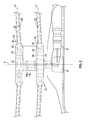
- the dual, counter-rotating, coaxial rotor system 12 includes an upper rotor system 16 and a lower rotor system 18.
- Each rotor system 16, 18 includes a plurality of rotor blade assemblies 20 mounted to a rotor hub assembly 22, 24 for rotation about the rotor axis of rotation A.
- the rotor hub assembly 22 is mounted to the upper rotor shaft 14U which counter rotates within the lower rotor shaft 14L, which rotates with the lower hub assembly 24.
- the plurality of main rotor blade assemblies 20 project substantially radially outward from the hub assemblies 22, 24. Any number of main rotor blade assemblies 20 may be used with the rotor system 12.
- Each rotor blade assembly 20 of the rotor system 12 generally includes a rotor blade 28 (illustrated somewhat schematically), a rotor blade spindle 30, and a rotor blade bearing 32, which supports the rotor blade spindle 30 within a bearing housing 34 to permit the rotor blade 28 to pitch about a pitching axis P. It should be understood that various blade attachments may be utilized with the present invention.
- a lower rotor independent blade control (IBC) system 36 includes an electrical actuator 38 directly or indirectly coupled to the rotor blade spindle 30 of each lower rotor blade 28.
- an upper rotor IBC system 44 includes an electrical actuator 46 coupled to the rotor blade spindle 30 of each upper rotor blade 28.
- the actuators 38, 46 are configured to impart a desired pitch control to the rotor blades 28.
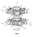
- each actuator 38, 46 is mounted to a respective rotor hub 22, 24 adjacent one of the plurality of rotor blade spindles 30 such that the actuators 38, 46 rotate about an axis R parallel to the axis P of an adjacent rotor blade 28.
- each actuator 38, 46 is transferred to a corresponding rotor blade 28 through a linkage 50, such as a connector or gear chain for example.
- a linkage 50 such as a connector or gear chain for example.
- Each actuator 38, 46 of each rotor system 36, 44 may be independently controlled. However, the plurality of actuators 38, 46 within each rotor control system 36, 44 are commonly controlled together. In one embodiment, the actuators 38, 46 are used to similarly rotate the rotor blades 28 of each rotor system 16, 18, thereby varying the pitch at frequencies of (N-1)P, NP, and (N+1)P with respect to axes P for vibration control. Additionally for primary control, the plurality of actuators 38, 46 within each rotor control system 36, 44 may be used to vary the pitch of the rotor blades 28 collectively and cyclically.
- the rotor control systems 36, 44 are configured to communicate with a flight control system (not shown) which receives pilot inputs from inceptors such as a collective stick, a cyclic stick, foot pedals, and the like, and upon which the higher harmonic control (HHC) commands are superimposed.
- a flight control system not shown
- inceptors such as a collective stick, a cyclic stick, foot pedals, and the like
- the main rotor system 12 is mounted to the airframe F at a location L and vibrations thereto are transferred at location L.
- Each of the upper and lower rotor system 16, 18 generates six unique vibratory loads.
- the counter-rotating, coaxial rotor system 12 thereby provides twelve vibratory hub loads.
- the twelve vibratory hub loads combine in the rotor system 12 to yield six loads applied to the airframe F at the location L.
- the two rotor systems 16, 18 do not produce the same set of three six-force patterns because of the difference in position of the two rotor systems 16, 18 i.e., they have different "leverage" with regard to location L.
- the six net vibratory hub loads at location L call for individual suppression to reduce airframe vibration.
- the dual, counter-rotating, coaxial rotor system 12 provides individual control of the upper rotor system 16 and the lower rotor system 18.
- the lower rotor control system 36 and the upper rotor control system 44 provide a total of six controls or "knobs" to reduce or theoretically eliminate air-frame vibration.
- application of HHC to the two rotor systems 16, 18 of a dual, counter-rotating, coaxial rotor system 12 may yield essentially complete vibration reduction because the six controls can sufficiently suppress the six loads.
- force generators of an active vibration control (AVC) system positioned throughout the airframe F may be used in combination with the HHC system to minimize the vibration in the airframe F.
- AVC active vibration control
- an HHC system 52 generally includes a controller 54 and a sensor system 56 in communication with the controller 54.
- the controller 54 is operably coupled to the actuators 38, 46 of the lower and upper rotor control systems 36, 44.
- the controller 54 is in communication with the sensor system 56 to sense vibration within the airframe F. It should be understood that various sensors at various locations may be utilized with the present invention.
- the controller 54 is an adaptive controller configured to control the plurality of actuators 38 of the lower rotor control system 36 and the plurality of actuators 46 of the upper rotor control system 44 separately.
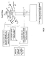
- the controller 54 may provide closed loop control of the plurality of actuators 38, 46 to reduce vibration thereof in accordance with an HHC algorithm ( FIGS. 7A and 7B ).
- the upper rotor control system 44 and the lower rotor control system 36 are preferably overlaid or integrated with the pilot inputs with the plurality of actuators 38, 46. It should be understood that various actuator systems may be utilized with the present invention so long as active control is provided individually in each axis of both the upper and lower rotor system 16, 18.
- the controller 54 uses the information provided by the sensors 56 to calculate a command for each of the plurality of force generators, illustrated schematically at FG, in addition to calculating commands for the plurality of rotating system actuators 38, 46.
- the matrix arithmetic shown in FIG. 7A is a math model that represents how the six HHC controls, U, three from each rotor control system 36, 44, influence the six net hub loads F.
- the square matrix T quantitatively relates the influence of U on F.
- Well known mathematics indicates that if the matrix T is square, and each column of T is independent, then matrix T can be "inverted" and a control solution, U can be found that will make all elements of F equal to zero. This is a math illustration of why six controls of known (U) are may be used to reduce or completely nullify six hub loads. If only three unique values of U existed, it would be difficult to completely nullify F. It should be understood that the matrix arithmetic shown in FIG.
Landscapes
- Engineering & Computer Science (AREA)
- Mechanical Engineering (AREA)
- Aviation & Aerospace Engineering (AREA)
- Wind Motors (AREA)
Applications Claiming Priority (1)
| Application Number | Priority Date | Filing Date | Title |
|---|---|---|---|
| US13/867,402 US10351233B2 (en) | 2013-04-22 | 2013-04-22 | Vibration control of a swashplateless coaxial rotor |
Publications (2)
| Publication Number | Publication Date |
|---|---|
| EP2803570A1 true EP2803570A1 (de) | 2014-11-19 |
| EP2803570B1 EP2803570B1 (de) | 2017-12-13 |
Family
ID=50542843
Family Applications (1)
| Application Number | Title | Priority Date | Filing Date |
|---|---|---|---|
| EP14165206.5A Not-in-force EP2803570B1 (de) | 2013-04-22 | 2014-04-17 | Schwingungssteuerung eines taumelscheibenlosen Koaxialrotors |
Country Status (2)
| Country | Link |
|---|---|
| US (1) | US10351233B2 (de) |
| EP (1) | EP2803570B1 (de) |
Cited By (4)
| Publication number | Priority date | Publication date | Assignee | Title |
|---|---|---|---|---|
| EP3431392A1 (de) * | 2017-07-19 | 2019-01-23 | Sikorsky Aircraft Corporation | Mit aktiver schwingungssteuerung erweiterte higher harmonic control |
| US10351233B2 (en) | 2013-04-22 | 2019-07-16 | Sikorsky Aircraft Corporation | Vibration control of a swashplateless coaxial rotor |
| EP3594116A1 (de) * | 2018-07-13 | 2020-01-15 | Bell Helicopter Textron Inc. | Nabenmontiertes vibrationsreduzierungssystem für koaxialrotorsysteme |
| IT202300006558A1 (it) | 2023-04-04 | 2024-10-04 | Mario Burigo | Velivolo elettrico a rotore coassiale |
Families Citing this family (9)
| Publication number | Priority date | Publication date | Assignee | Title |
|---|---|---|---|---|
| EP3201077B1 (de) | 2014-10-01 | 2020-05-20 | Sikorsky Aircraft Corporation | Doppelrotor, drehflügelflugzeug |
| US20170267338A1 (en) | 2014-10-01 | 2017-09-21 | Sikorsky Aircraft Corporation | Acoustic signature variation of aircraft utilizing a clutch |
| US10302064B2 (en) * | 2015-07-30 | 2019-05-28 | The Boeing Company | Methods and systems for rotary wing active flow control |
| IL240316B (en) | 2015-08-03 | 2018-10-31 | Technion Res & Dev Foundation | Method and system for parametric amplification |
| US20170129597A1 (en) * | 2015-11-10 | 2017-05-11 | Sikorsky Aircraft Corporation | Reduced power individual blade control system on a rotorcraft |
| US10988263B2 (en) * | 2016-12-08 | 2021-04-27 | Thomas Francis Daily, JR. | VTOL aircraft with jet engine coupled to downward thrust nozzles |
| US20180265186A1 (en) | 2017-03-15 | 2018-09-20 | Bell Helicopter Textron Inc. | Vibration Isolation Systems for Advancing Blade Concept Rotorcraft |
| US11932380B2 (en) | 2017-03-15 | 2024-03-19 | Textron Innovations Inc. | Vibration isolation systems for compound helicopters |
| AU2020251052B2 (en) * | 2019-04-04 | 2025-05-08 | Hyper Q Aerospace Holdings Pty Ltd | A coaxial rotorcraft system and a method for controlling the same |
Citations (6)
| Publication number | Priority date | Publication date | Assignee | Title |
|---|---|---|---|---|
| US20030060903A1 (en) * | 2001-02-27 | 2003-03-27 | Macmartin Douglas G. | System for computationally efficient adaptation of active control of sound or vibration |
| WO2008033884A2 (en) * | 2006-09-14 | 2008-03-20 | Sikorsky Aircraft Corporation | Dual higher harmonic control (hhc) for a counter-rotating, coaxial rotor system |
| US20090269199A1 (en) * | 2008-04-24 | 2009-10-29 | The Boeing Company | Swashplateless helicopter blade actuation system |
| US20100150719A1 (en) * | 2008-12-12 | 2010-06-17 | Karem Aircraft, Inc. | Swashplateless rotorcraft with fault tolerant linear electric actuator |
| WO2012076705A2 (fr) * | 2010-12-09 | 2012-06-14 | Altade | Rotor d'aéronef à ailes rotatives |
| US20120181379A1 (en) * | 2011-01-14 | 2012-07-19 | Sikorsky Aircraft Corporation | Moment limiting control laws for dual rigid rotor helicopters |
Family Cites Families (13)
| Publication number | Priority date | Publication date | Assignee | Title |
|---|---|---|---|---|
| FR2624473B1 (fr) | 1987-12-15 | 1990-05-18 | Aerospatiale | Dispositif hydraulique de commande individuelle du pas d'une pale de rotor, et moyeu de rotor et rotor equipes de tels dispositifs |
| GB9104189D0 (en) * | 1991-02-28 | 1991-06-12 | Westland Helicopters | Active vibration control systems |
| JP2758374B2 (ja) * | 1995-02-28 | 1998-05-28 | 株式会社コミュータヘリコプタ先進技術研究所 | ヘリコプタロータの高調波制御装置 |
| AU2003304209A1 (en) | 2002-09-24 | 2005-01-04 | Bell Helicopter Textron Inc. | Piezoelectric liquid inertia vibration eliminator |
| US7900869B2 (en) * | 2004-05-06 | 2011-03-08 | Zf Friedrichshafen Ag | Helicopter rotor control system with individual blade control |
| US8235324B1 (en) * | 2009-03-03 | 2012-08-07 | Orbital Research Inc. | Rotorcraft with electrically driven blade control |
| US20120292434A1 (en) | 2011-04-29 | 2012-11-22 | Sikorsky Aircraft Corporation | Six Degrees Of Freedom Vibration Suppression |
| WO2014022910A1 (en) | 2012-08-07 | 2014-02-13 | Smart Rotor Systems Inc. | Smart active vibration supression systems |
| US10351233B2 (en) | 2013-04-22 | 2019-07-16 | Sikorsky Aircraft Corporation | Vibration control of a swashplateless coaxial rotor |
| KR20160078421A (ko) | 2013-10-31 | 2016-07-04 | 로오드 코포레이션 | 동역학적 피치 조절 디바이스, 시스템 및 방법 |
| US20170267338A1 (en) | 2014-10-01 | 2017-09-21 | Sikorsky Aircraft Corporation | Acoustic signature variation of aircraft utilizing a clutch |
| US20170088257A1 (en) | 2015-09-30 | 2017-03-30 | Bell Helicopter Textron Inc. | Unified control of multiple active systems for helicopter vibration suppression |
| US10543912B2 (en) | 2017-07-19 | 2020-01-28 | Sikorsky Aircraft Corporation | Higher harmonic control augmented with active vibration control |
-
2013
- 2013-04-22 US US13/867,402 patent/US10351233B2/en not_active Expired - Fee Related
-
2014
- 2014-04-17 EP EP14165206.5A patent/EP2803570B1/de not_active Not-in-force
Patent Citations (6)
| Publication number | Priority date | Publication date | Assignee | Title |
|---|---|---|---|---|
| US20030060903A1 (en) * | 2001-02-27 | 2003-03-27 | Macmartin Douglas G. | System for computationally efficient adaptation of active control of sound or vibration |
| WO2008033884A2 (en) * | 2006-09-14 | 2008-03-20 | Sikorsky Aircraft Corporation | Dual higher harmonic control (hhc) for a counter-rotating, coaxial rotor system |
| US20090269199A1 (en) * | 2008-04-24 | 2009-10-29 | The Boeing Company | Swashplateless helicopter blade actuation system |
| US20100150719A1 (en) * | 2008-12-12 | 2010-06-17 | Karem Aircraft, Inc. | Swashplateless rotorcraft with fault tolerant linear electric actuator |
| WO2012076705A2 (fr) * | 2010-12-09 | 2012-06-14 | Altade | Rotor d'aéronef à ailes rotatives |
| US20120181379A1 (en) * | 2011-01-14 | 2012-07-19 | Sikorsky Aircraft Corporation | Moment limiting control laws for dual rigid rotor helicopters |
Cited By (7)
| Publication number | Priority date | Publication date | Assignee | Title |
|---|---|---|---|---|
| US10351233B2 (en) | 2013-04-22 | 2019-07-16 | Sikorsky Aircraft Corporation | Vibration control of a swashplateless coaxial rotor |
| EP3431392A1 (de) * | 2017-07-19 | 2019-01-23 | Sikorsky Aircraft Corporation | Mit aktiver schwingungssteuerung erweiterte higher harmonic control |
| US10543912B2 (en) | 2017-07-19 | 2020-01-28 | Sikorsky Aircraft Corporation | Higher harmonic control augmented with active vibration control |
| EP3594116A1 (de) * | 2018-07-13 | 2020-01-15 | Bell Helicopter Textron Inc. | Nabenmontiertes vibrationsreduzierungssystem für koaxialrotorsysteme |
| US10933984B2 (en) | 2018-07-13 | 2021-03-02 | Textron Innovations Inc. | Hub mounted vibration reduction system for coaxial rotor systems |
| WO2024209496A1 (en) | 2023-04-03 | 2024-10-10 | Mario Burigo | Electric coaxial rotor aircraft |
| IT202300006558A1 (it) | 2023-04-04 | 2024-10-04 | Mario Burigo | Velivolo elettrico a rotore coassiale |
Also Published As
| Publication number | Publication date |
|---|---|
| EP2803570B1 (de) | 2017-12-13 |
| US10351233B2 (en) | 2019-07-16 |
| US20140314563A1 (en) | 2014-10-23 |
Similar Documents
| Publication | Publication Date | Title |
|---|---|---|
| EP2803570B1 (de) | Schwingungssteuerung eines taumelscheibenlosen Koaxialrotors | |
| EP2076436B1 (de) | Doppelte oberschwingungssteuerung für ein koaxialrotorensystem mit gegenschwingung | |
| EP3431392B1 (de) | Mit aktiver schwingungssteuerung erweiterte higher harmonic control | |
| US10065730B2 (en) | Active vibration control system with non-concentric revolving masses | |
| US9181811B2 (en) | Device for varying lade pitch of a lift rotor | |
| US9248909B2 (en) | Swashplateless coaxial rotary wing aircraft | |
| US11760472B2 (en) | Rudders for rotorcraft yaw control systems | |
| EP2796368B1 (de) | Integration von elektrischem Drehaktuator für taumelscheibenlose Steuerung einzelner Blätter | |
| US10745116B2 (en) | Anti-vibration load generating aircraft actuation system | |
| US11720123B2 (en) | Airframe protection systems for use on rotorcraft | |
| US9139298B2 (en) | Rotorcraft control system for rotorcraft with two or more rotor systems | |
| EP3126231A1 (de) | Höhenruderlastreduzierungssteuerung für ein drehflügelflugzeug | |
| CA2829734C (en) | Direct-drive control of aircraft stability augmentation | |
| US10538314B2 (en) | Anti-vibration moment generating aircraft actuation system | |
| WO2016123055A1 (en) | Active rotor damping system | |
| EP3650339B1 (de) | System und verfahren für frequenzbereichs-rotormodusdekomposition | |
| EP3057866B1 (de) | Giersteuerung für einen koaxialrotor | |
| US20240208645A1 (en) | Anti-Backlash Flight Control Actuator System | |
| US20230271713A1 (en) | Aircraft Component Longevity | |
| EP2927120B1 (de) | Flexible Flügel-Steuerung für Flugzeuge | |
| US10994834B2 (en) | Case mounted transmission AVC force generators | |
| EP3566945B1 (de) | Schwingungsunterdrückungssystem mit mehreren freiheitsgraden zur steuerung von durch einen hauptrotorwirbelströmung induzierten schwingungen auf heckflächen eines drehflügelflugzeugs | |
| Reilly et al. | Achieving Automated Rotor Track and Balance through use of Active Trim Tab and Pitch Control Rod Technologies |
Legal Events
| Date | Code | Title | Description |
|---|---|---|---|
| PUAI | Public reference made under article 153(3) epc to a published international application that has entered the european phase |
Free format text: ORIGINAL CODE: 0009012 |
|
| 17P | Request for examination filed |
Effective date: 20140417 |
|
| AK | Designated contracting states |
Kind code of ref document: A1 Designated state(s): AL AT BE BG CH CY CZ DE DK EE ES FI FR GB GR HR HU IE IS IT LI LT LU LV MC MK MT NL NO PL PT RO RS SE SI SK SM TR |
|
| AX | Request for extension of the european patent |
Extension state: BA ME |
|
| R17P | Request for examination filed (corrected) |
Effective date: 20150519 |
|
| RBV | Designated contracting states (corrected) |
Designated state(s): AL AT BE BG CH CY CZ DE DK EE ES FI FR GB GR HR HU IE IS IT LI LT LU LV MC MK MT NL NO PL PT RO RS SE SI SK SM TR |
|
| 17Q | First examination report despatched |
Effective date: 20160517 |
|
| GRAP | Despatch of communication of intention to grant a patent |
Free format text: ORIGINAL CODE: EPIDOSNIGR1 |
|
| INTG | Intention to grant announced |
Effective date: 20170627 |
|
| GRAS | Grant fee paid |
Free format text: ORIGINAL CODE: EPIDOSNIGR3 |
|
| GRAA | (expected) grant |
Free format text: ORIGINAL CODE: 0009210 |
|
| REG | Reference to a national code |
Ref country code: GB Ref legal event code: FG4D |
|
| REG | Reference to a national code |
Ref country code: AT Ref legal event code: REF Ref document number: 954103 Country of ref document: AT Kind code of ref document: T Effective date: 20171215 Ref country code: CH Ref legal event code: EP |
|
| REG | Reference to a national code |
Ref country code: IE Ref legal event code: FG4D |
|
| REG | Reference to a national code |
Ref country code: DE Ref legal event code: R096 Ref document number: 602014018388 Country of ref document: DE |
|
| REG | Reference to a national code |
Ref country code: NL Ref legal event code: MP Effective date: 20171213 |
|
| REG | Reference to a national code |
Ref country code: FR Ref legal event code: PLFP Year of fee payment: 5 |
|
| PG25 | Lapsed in a contracting state [announced via postgrant information from national office to epo] |
Ref country code: FI Free format text: LAPSE BECAUSE OF FAILURE TO SUBMIT A TRANSLATION OF THE DESCRIPTION OR TO PAY THE FEE WITHIN THE PRESCRIBED TIME-LIMIT Effective date: 20171213 Ref country code: SE Free format text: LAPSE BECAUSE OF FAILURE TO SUBMIT A TRANSLATION OF THE DESCRIPTION OR TO PAY THE FEE WITHIN THE PRESCRIBED TIME-LIMIT Effective date: 20171213 Ref country code: NO Free format text: LAPSE BECAUSE OF FAILURE TO SUBMIT A TRANSLATION OF THE DESCRIPTION OR TO PAY THE FEE WITHIN THE PRESCRIBED TIME-LIMIT Effective date: 20180313 |
|
| REG | Reference to a national code |
Ref country code: AT Ref legal event code: MK05 Ref document number: 954103 Country of ref document: AT Kind code of ref document: T Effective date: 20171213 |
|
| PG25 | Lapsed in a contracting state [announced via postgrant information from national office to epo] |
Ref country code: LV Free format text: LAPSE BECAUSE OF FAILURE TO SUBMIT A TRANSLATION OF THE DESCRIPTION OR TO PAY THE FEE WITHIN THE PRESCRIBED TIME-LIMIT Effective date: 20171213 Ref country code: GR Free format text: LAPSE BECAUSE OF FAILURE TO SUBMIT A TRANSLATION OF THE DESCRIPTION OR TO PAY THE FEE WITHIN THE PRESCRIBED TIME-LIMIT Effective date: 20180314 Ref country code: RS Free format text: LAPSE BECAUSE OF FAILURE TO SUBMIT A TRANSLATION OF THE DESCRIPTION OR TO PAY THE FEE WITHIN THE PRESCRIBED TIME-LIMIT Effective date: 20171213 Ref country code: BG Free format text: LAPSE BECAUSE OF FAILURE TO SUBMIT A TRANSLATION OF THE DESCRIPTION OR TO PAY THE FEE WITHIN THE PRESCRIBED TIME-LIMIT Effective date: 20180313 Ref country code: HR Free format text: LAPSE BECAUSE OF FAILURE TO SUBMIT A TRANSLATION OF THE DESCRIPTION OR TO PAY THE FEE WITHIN THE PRESCRIBED TIME-LIMIT Effective date: 20171213 |
|
| PG25 | Lapsed in a contracting state [announced via postgrant information from national office to epo] |
Ref country code: NL Free format text: LAPSE BECAUSE OF FAILURE TO SUBMIT A TRANSLATION OF THE DESCRIPTION OR TO PAY THE FEE WITHIN THE PRESCRIBED TIME-LIMIT Effective date: 20171213 |
|
| PG25 | Lapsed in a contracting state [announced via postgrant information from national office to epo] |
Ref country code: EE Free format text: LAPSE BECAUSE OF FAILURE TO SUBMIT A TRANSLATION OF THE DESCRIPTION OR TO PAY THE FEE WITHIN THE PRESCRIBED TIME-LIMIT Effective date: 20171213 Ref country code: CY Free format text: LAPSE BECAUSE OF FAILURE TO SUBMIT A TRANSLATION OF THE DESCRIPTION OR TO PAY THE FEE WITHIN THE PRESCRIBED TIME-LIMIT Effective date: 20171213 Ref country code: CZ Free format text: LAPSE BECAUSE OF FAILURE TO SUBMIT A TRANSLATION OF THE DESCRIPTION OR TO PAY THE FEE WITHIN THE PRESCRIBED TIME-LIMIT Effective date: 20171213 Ref country code: SK Free format text: LAPSE BECAUSE OF FAILURE TO SUBMIT A TRANSLATION OF THE DESCRIPTION OR TO PAY THE FEE WITHIN THE PRESCRIBED TIME-LIMIT Effective date: 20171213 |
|
| PG25 | Lapsed in a contracting state [announced via postgrant information from national office to epo] |
Ref country code: AT Free format text: LAPSE BECAUSE OF FAILURE TO SUBMIT A TRANSLATION OF THE DESCRIPTION OR TO PAY THE FEE WITHIN THE PRESCRIBED TIME-LIMIT Effective date: 20171213 Ref country code: PL Free format text: LAPSE BECAUSE OF FAILURE TO SUBMIT A TRANSLATION OF THE DESCRIPTION OR TO PAY THE FEE WITHIN THE PRESCRIBED TIME-LIMIT Effective date: 20171213 Ref country code: IS Free format text: LAPSE BECAUSE OF FAILURE TO SUBMIT A TRANSLATION OF THE DESCRIPTION OR TO PAY THE FEE WITHIN THE PRESCRIBED TIME-LIMIT Effective date: 20180413 Ref country code: SM Free format text: LAPSE BECAUSE OF FAILURE TO SUBMIT A TRANSLATION OF THE DESCRIPTION OR TO PAY THE FEE WITHIN THE PRESCRIBED TIME-LIMIT Effective date: 20171213 Ref country code: RO Free format text: LAPSE BECAUSE OF FAILURE TO SUBMIT A TRANSLATION OF THE DESCRIPTION OR TO PAY THE FEE WITHIN THE PRESCRIBED TIME-LIMIT Effective date: 20171213 |
|
| REG | Reference to a national code |
Ref country code: DE Ref legal event code: R097 Ref document number: 602014018388 Country of ref document: DE |
|
| PLBE | No opposition filed within time limit |
Free format text: ORIGINAL CODE: 0009261 |
|
| STAA | Information on the status of an ep patent application or granted ep patent |
Free format text: STATUS: NO OPPOSITION FILED WITHIN TIME LIMIT |
|
| 26N | No opposition filed |
Effective date: 20180914 |
|
| PG25 | Lapsed in a contracting state [announced via postgrant information from national office to epo] |
Ref country code: DK Free format text: LAPSE BECAUSE OF FAILURE TO SUBMIT A TRANSLATION OF THE DESCRIPTION OR TO PAY THE FEE WITHIN THE PRESCRIBED TIME-LIMIT Effective date: 20171213 Ref country code: MC Free format text: LAPSE BECAUSE OF FAILURE TO SUBMIT A TRANSLATION OF THE DESCRIPTION OR TO PAY THE FEE WITHIN THE PRESCRIBED TIME-LIMIT Effective date: 20171213 |
|
| REG | Reference to a national code |
Ref country code: CH Ref legal event code: PL |
|
| REG | Reference to a national code |
Ref country code: BE Ref legal event code: MM Effective date: 20180430 |
|
| REG | Reference to a national code |
Ref country code: IE Ref legal event code: MM4A |
|
| PG25 | Lapsed in a contracting state [announced via postgrant information from national office to epo] |
Ref country code: LU Free format text: LAPSE BECAUSE OF NON-PAYMENT OF DUE FEES Effective date: 20180417 |
|
| PG25 | Lapsed in a contracting state [announced via postgrant information from national office to epo] |
Ref country code: SI Free format text: LAPSE BECAUSE OF FAILURE TO SUBMIT A TRANSLATION OF THE DESCRIPTION OR TO PAY THE FEE WITHIN THE PRESCRIBED TIME-LIMIT Effective date: 20171213 Ref country code: LI Free format text: LAPSE BECAUSE OF NON-PAYMENT OF DUE FEES Effective date: 20180430 Ref country code: BE Free format text: LAPSE BECAUSE OF NON-PAYMENT OF DUE FEES Effective date: 20180430 Ref country code: CH Free format text: LAPSE BECAUSE OF NON-PAYMENT OF DUE FEES Effective date: 20180430 |
|
| PG25 | Lapsed in a contracting state [announced via postgrant information from national office to epo] |
Ref country code: IE Free format text: LAPSE BECAUSE OF NON-PAYMENT OF DUE FEES Effective date: 20180417 |
|
| PG25 | Lapsed in a contracting state [announced via postgrant information from national office to epo] |
Ref country code: ES Free format text: LAPSE BECAUSE OF FAILURE TO SUBMIT A TRANSLATION OF THE DESCRIPTION OR TO PAY THE FEE WITHIN THE PRESCRIBED TIME-LIMIT Effective date: 20171213 |
|
| PGFP | Annual fee paid to national office [announced via postgrant information from national office to epo] |
Ref country code: DE Payment date: 20190429 Year of fee payment: 6 Ref country code: IT Payment date: 20190423 Year of fee payment: 6 |
|
| PGFP | Annual fee paid to national office [announced via postgrant information from national office to epo] |
Ref country code: FR Payment date: 20190425 Year of fee payment: 6 |
|
| PGFP | Annual fee paid to national office [announced via postgrant information from national office to epo] |
Ref country code: GB Payment date: 20190429 Year of fee payment: 6 |
|
| PG25 | Lapsed in a contracting state [announced via postgrant information from national office to epo] |
Ref country code: MT Free format text: LAPSE BECAUSE OF NON-PAYMENT OF DUE FEES Effective date: 20180417 |
|
| PG25 | Lapsed in a contracting state [announced via postgrant information from national office to epo] |
Ref country code: TR Free format text: LAPSE BECAUSE OF FAILURE TO SUBMIT A TRANSLATION OF THE DESCRIPTION OR TO PAY THE FEE WITHIN THE PRESCRIBED TIME-LIMIT Effective date: 20171213 |
|
| PG25 | Lapsed in a contracting state [announced via postgrant information from national office to epo] |
Ref country code: HU Free format text: LAPSE BECAUSE OF FAILURE TO SUBMIT A TRANSLATION OF THE DESCRIPTION OR TO PAY THE FEE WITHIN THE PRESCRIBED TIME-LIMIT; INVALID AB INITIO Effective date: 20140417 Ref country code: PT Free format text: LAPSE BECAUSE OF FAILURE TO SUBMIT A TRANSLATION OF THE DESCRIPTION OR TO PAY THE FEE WITHIN THE PRESCRIBED TIME-LIMIT Effective date: 20171213 |
|
| PG25 | Lapsed in a contracting state [announced via postgrant information from national office to epo] |
Ref country code: MK Free format text: LAPSE BECAUSE OF NON-PAYMENT OF DUE FEES Effective date: 20171213 Ref country code: LT Free format text: LAPSE BECAUSE OF FAILURE TO SUBMIT A TRANSLATION OF THE DESCRIPTION OR TO PAY THE FEE WITHIN THE PRESCRIBED TIME-LIMIT Effective date: 20171213 |
|
| PG25 | Lapsed in a contracting state [announced via postgrant information from national office to epo] |
Ref country code: AL Free format text: LAPSE BECAUSE OF FAILURE TO SUBMIT A TRANSLATION OF THE DESCRIPTION OR TO PAY THE FEE WITHIN THE PRESCRIBED TIME-LIMIT Effective date: 20171213 |
|
| REG | Reference to a national code |
Ref country code: DE Ref legal event code: R119 Ref document number: 602014018388 Country of ref document: DE |
|
| PG25 | Lapsed in a contracting state [announced via postgrant information from national office to epo] |
Ref country code: DE Free format text: LAPSE BECAUSE OF NON-PAYMENT OF DUE FEES Effective date: 20201103 Ref country code: FR Free format text: LAPSE BECAUSE OF NON-PAYMENT OF DUE FEES Effective date: 20200430 |
|
| GBPC | Gb: european patent ceased through non-payment of renewal fee |
Effective date: 20200417 |
|
| PG25 | Lapsed in a contracting state [announced via postgrant information from national office to epo] |
Ref country code: GB Free format text: LAPSE BECAUSE OF NON-PAYMENT OF DUE FEES Effective date: 20200417 |
|
| PG25 | Lapsed in a contracting state [announced via postgrant information from national office to epo] |
Ref country code: IT Free format text: LAPSE BECAUSE OF NON-PAYMENT OF DUE FEES Effective date: 20200417 |