EP2803490B1 - Printing fluid cartridge and printing apparatus - Google Patents
Printing fluid cartridge and printing apparatus Download PDFInfo
- Publication number
- EP2803490B1 EP2803490B1 EP14180945.9A EP14180945A EP2803490B1 EP 2803490 B1 EP2803490 B1 EP 2803490B1 EP 14180945 A EP14180945 A EP 14180945A EP 2803490 B1 EP2803490 B1 EP 2803490B1
- Authority
- EP
- European Patent Office
- Prior art keywords
- ink
- cartridge
- printing fluid
- ink cartridge
- mounting portion
- Prior art date
- Legal status (The legal status is an assumption and is not a legal conclusion. Google has not performed a legal analysis and makes no representation as to the accuracy of the status listed.)
- Active
Links
- 238000007639 printing Methods 0.000 title claims description 91
- 239000012530 fluid Substances 0.000 title claims description 67
- 238000003780 insertion Methods 0.000 claims description 136
- 230000037431 insertion Effects 0.000 claims description 136
- 238000004519 manufacturing process Methods 0.000 claims description 4
- 230000003287 optical effect Effects 0.000 description 146
- 238000001514 detection method Methods 0.000 description 145
- 238000004891 communication Methods 0.000 description 44
- 239000000428 dust Substances 0.000 description 20
- 239000004615 ingredient Substances 0.000 description 4
- 239000004065 semiconductor Substances 0.000 description 4
- 239000003086 colorant Substances 0.000 description 3
- 238000005192 partition Methods 0.000 description 3
- 239000000049 pigment Substances 0.000 description 3
- 230000000717 retained effect Effects 0.000 description 3
- 238000006073 displacement reaction Methods 0.000 description 2
- 241000656145 Thyrsites atun Species 0.000 description 1
- 239000000853 adhesive Substances 0.000 description 1
- 230000001070 adhesive effect Effects 0.000 description 1
- 238000006243 chemical reaction Methods 0.000 description 1
- 230000007423 decrease Effects 0.000 description 1
- 230000001419 dependent effect Effects 0.000 description 1
- 238000007641 inkjet printing Methods 0.000 description 1
- 238000012423 maintenance Methods 0.000 description 1
- 238000000034 method Methods 0.000 description 1
- 238000012986 modification Methods 0.000 description 1
- 230000004048 modification Effects 0.000 description 1
- 229920005989 resin Polymers 0.000 description 1
- 239000011347 resin Substances 0.000 description 1
- 230000003068 static effect Effects 0.000 description 1
- 229920003002 synthetic resin Polymers 0.000 description 1
- 239000000057 synthetic resin Substances 0.000 description 1
Images


Classifications
-
- B—PERFORMING OPERATIONS; TRANSPORTING
- B41—PRINTING; LINING MACHINES; TYPEWRITERS; STAMPS
- B41J—TYPEWRITERS; SELECTIVE PRINTING MECHANISMS, i.e. MECHANISMS PRINTING OTHERWISE THAN FROM A FORME; CORRECTION OF TYPOGRAPHICAL ERRORS
- B41J2/00—Typewriters or selective printing mechanisms characterised by the printing or marking process for which they are designed
- B41J2/005—Typewriters or selective printing mechanisms characterised by the printing or marking process for which they are designed characterised by bringing liquid or particles selectively into contact with a printing material
- B41J2/01—Ink jet
- B41J2/17—Ink jet characterised by ink handling
- B41J2/175—Ink supply systems ; Circuit parts therefor
- B41J2/17503—Ink cartridges
- B41J2/17513—Inner structure
-
- B—PERFORMING OPERATIONS; TRANSPORTING
- B41—PRINTING; LINING MACHINES; TYPEWRITERS; STAMPS
- B41J—TYPEWRITERS; SELECTIVE PRINTING MECHANISMS, i.e. MECHANISMS PRINTING OTHERWISE THAN FROM A FORME; CORRECTION OF TYPOGRAPHICAL ERRORS
- B41J2/00—Typewriters or selective printing mechanisms characterised by the printing or marking process for which they are designed
- B41J2/005—Typewriters or selective printing mechanisms characterised by the printing or marking process for which they are designed characterised by bringing liquid or particles selectively into contact with a printing material
- B41J2/01—Ink jet
- B41J2/17—Ink jet characterised by ink handling
- B41J2/175—Ink supply systems ; Circuit parts therefor
- B41J2/17503—Ink cartridges
- B41J2/17506—Refilling of the cartridge
- B41J2/17509—Whilst mounted in the printer
-
- B—PERFORMING OPERATIONS; TRANSPORTING
- B41—PRINTING; LINING MACHINES; TYPEWRITERS; STAMPS
- B41J—TYPEWRITERS; SELECTIVE PRINTING MECHANISMS, i.e. MECHANISMS PRINTING OTHERWISE THAN FROM A FORME; CORRECTION OF TYPOGRAPHICAL ERRORS
- B41J2/00—Typewriters or selective printing mechanisms characterised by the printing or marking process for which they are designed
- B41J2/005—Typewriters or selective printing mechanisms characterised by the printing or marking process for which they are designed characterised by bringing liquid or particles selectively into contact with a printing material
- B41J2/01—Ink jet
- B41J2/17—Ink jet characterised by ink handling
- B41J2/175—Ink supply systems ; Circuit parts therefor
- B41J2/17503—Ink cartridges
- B41J2/1752—Mounting within the printer
- B41J2/17523—Ink connection
-
- B—PERFORMING OPERATIONS; TRANSPORTING
- B41—PRINTING; LINING MACHINES; TYPEWRITERS; STAMPS
- B41J—TYPEWRITERS; SELECTIVE PRINTING MECHANISMS, i.e. MECHANISMS PRINTING OTHERWISE THAN FROM A FORME; CORRECTION OF TYPOGRAPHICAL ERRORS
- B41J2/00—Typewriters or selective printing mechanisms characterised by the printing or marking process for which they are designed
- B41J2/005—Typewriters or selective printing mechanisms characterised by the printing or marking process for which they are designed characterised by bringing liquid or particles selectively into contact with a printing material
- B41J2/01—Ink jet
- B41J2/17—Ink jet characterised by ink handling
- B41J2/175—Ink supply systems ; Circuit parts therefor
- B41J2/17503—Ink cartridges
- B41J2/17526—Electrical contacts to the cartridge
- B41J2/1753—Details of contacts on the cartridge, e.g. protection of contacts
-
- B—PERFORMING OPERATIONS; TRANSPORTING
- B41—PRINTING; LINING MACHINES; TYPEWRITERS; STAMPS
- B41J—TYPEWRITERS; SELECTIVE PRINTING MECHANISMS, i.e. MECHANISMS PRINTING OTHERWISE THAN FROM A FORME; CORRECTION OF TYPOGRAPHICAL ERRORS
- B41J2/00—Typewriters or selective printing mechanisms characterised by the printing or marking process for which they are designed
- B41J2/005—Typewriters or selective printing mechanisms characterised by the printing or marking process for which they are designed characterised by bringing liquid or particles selectively into contact with a printing material
- B41J2/01—Ink jet
- B41J2/17—Ink jet characterised by ink handling
- B41J2/175—Ink supply systems ; Circuit parts therefor
- B41J2/17503—Ink cartridges
- B41J2/17543—Cartridge presence detection or type identification
- B41J2/17546—Cartridge presence detection or type identification electronically
-
- B—PERFORMING OPERATIONS; TRANSPORTING
- B41—PRINTING; LINING MACHINES; TYPEWRITERS; STAMPS
- B41J—TYPEWRITERS; SELECTIVE PRINTING MECHANISMS, i.e. MECHANISMS PRINTING OTHERWISE THAN FROM A FORME; CORRECTION OF TYPOGRAPHICAL ERRORS
- B41J2/00—Typewriters or selective printing mechanisms characterised by the printing or marking process for which they are designed
- B41J2/005—Typewriters or selective printing mechanisms characterised by the printing or marking process for which they are designed characterised by bringing liquid or particles selectively into contact with a printing material
- B41J2/01—Ink jet
- B41J2/17—Ink jet characterised by ink handling
- B41J2/175—Ink supply systems ; Circuit parts therefor
- B41J2/17503—Ink cartridges
- B41J2/17553—Outer structure
-
- B—PERFORMING OPERATIONS; TRANSPORTING
- B41—PRINTING; LINING MACHINES; TYPEWRITERS; STAMPS
- B41J—TYPEWRITERS; SELECTIVE PRINTING MECHANISMS, i.e. MECHANISMS PRINTING OTHERWISE THAN FROM A FORME; CORRECTION OF TYPOGRAPHICAL ERRORS
- B41J2/00—Typewriters or selective printing mechanisms characterised by the printing or marking process for which they are designed
- B41J2/005—Typewriters or selective printing mechanisms characterised by the printing or marking process for which they are designed characterised by bringing liquid or particles selectively into contact with a printing material
- B41J2/01—Ink jet
- B41J2/17—Ink jet characterised by ink handling
- B41J2/175—Ink supply systems ; Circuit parts therefor
- B41J2/17566—Ink level or ink residue control
- B41J2002/17573—Ink level or ink residue control using optical means for ink level indication
-
- B—PERFORMING OPERATIONS; TRANSPORTING
- B41—PRINTING; LINING MACHINES; TYPEWRITERS; STAMPS
- B41J—TYPEWRITERS; SELECTIVE PRINTING MECHANISMS, i.e. MECHANISMS PRINTING OTHERWISE THAN FROM A FORME; CORRECTION OF TYPOGRAPHICAL ERRORS
- B41J2/00—Typewriters or selective printing mechanisms characterised by the printing or marking process for which they are designed
- B41J2/005—Typewriters or selective printing mechanisms characterised by the printing or marking process for which they are designed characterised by bringing liquid or particles selectively into contact with a printing material
- B41J2/01—Ink jet
- B41J2/17—Ink jet characterised by ink handling
- B41J2/175—Ink supply systems ; Circuit parts therefor
- B41J2/17566—Ink level or ink residue control
- B41J2002/17576—Ink level or ink residue control using a floater for ink level indication
Landscapes
- Ink Jet (AREA)
Description
- The present invention relates to a printing fluid cartridge configured to be mounted to a cartridge mounting portion, and to a printing apparatus comprising such a printing fluid cartridge.
- A known image printing apparatus, as described in Patent Application Publication No.
JP 2009-132098 A - Another known ink cartridge, as described in Patent Application Publication No.
JP 2007-266618 - When dust adheres to the electrical interfaces, the electrical connection between the electrical interfaces of the ink cartridge and the contacts of the cartridge mounting portion may become unstable, such that the date fails to be read out from the semiconductor memory. Therefore, the dust may be wiped off the electrical interfaces. However, if the dust falls off the electrical interfaces, the dust may adhere to a portion of the ink cartridge surrounding an opening for supplying ink from an interior of the ink cartridge to an exterior of the ink cartridge. Ink contaminated by the dust may be supplied to a printing head.
-
EP 1 234 675 A2 discloses a printing fluid cartridge according to the preamble of claim 1. - Therefore, a need has arisen for a printing fluid cartridge and a printing apparatus, which overcome these and other shortcomings of the related art. A technical advantage of the present invention is that a likelihood that printing fluid is contaminated by dust which has adhered to an electrical interface is reduced.
- This object is achieved by the printing fluid cartridge having the features of claim 1. The present patent application is further developed as defined in the dependent claims. According to an embodiment of the present invention, a printing fluid cartridge is configured to be inserted into a cartridge mounting portion in an insertion direction intersecting a gravitational direction in an upright position. The printing fluid cartridge comprises a front face oriented toward the insertion direction when the printing fluid cartridge is inserted into the cartridge mounting portion, a rear face positioned opposite the front face with respect to the insertion direction and oriented toward the removal direction, when the printing fluid cartridge is inserted into the cartridge mounting portion, a top face extending between the front face and the rear face, and facing upward when the printing fluid cartridge is in the upright position a chamber configured to store printing fluid therein, an electrical interface disposed at the top face, such that the
electrical interface is exposed to an exterior of the printing fluid cartridge, a printing fluid supply portion comprising a printing fluid supply opening. The printing fluid supply portion is configured to supply the printing fluid from an interior of the chamber to an exterior of the chamber via the printing fluid supply opening. The printing fluid supply portion is positioned at the front face. The electrical interface is positioned above the printing fluid supply portion, when the printing fluid cartridge is in the upright position. The electrical interface is further positioned more rearward than the printing fluid supply opening with respect to the insertion direction. - With this configuration, because the electrical interface is positioned above and more rearward than the printing fluid supply opening with respect to the insertion direction, even if dust on the electrical interface falls down, a likelihood that such dust adheres to a portion of the printing fluid supply portion surrounding the printing fluid supply opening is reduced. Therefore, a likelihood that printing fluid is contaminated by the dust is reduced.
- Other objects, features, and advantages will be apparent to persons of ordinary skill in the art from the following detained description of the invention and the accompanying drawings.
- For a more complete understanding of the present invention, needs satisfied thereby, and the objects, features, and advantages thereof, reference now is made to the following description taken in connection with the accompanying drawings.
-
Fig. 1 is a schematic, cross-sectional view of a printer comprising a cartridge mounting portion and an ink cartridge, according to an embodiment of the present invention. -
Fig. 2 is a perspective view of the ink cartridge. -
Fig. 3 is an exploded, perspective view of the ink cartridge. -
Fig. 4 is a vertical, cross-sectional view of the ink cartridge. -
Fig. 5 is a perspective view of the cartridge mounting portion and the ink cartridge. -
Fig. 6 is a vertical, cross-sectional view of the cartridge mounting portion. -
Fig. 7 is a vertical, partial cross-sectional view of the cartridge mounting portion and the ink cartridge during mounting of the ink cartridge to the cartridge mounting portion. -
Fig. 8 is another vertical, partial cross-sectional view of the cartridge mounting portion and the ink cartridge during mounting of the ink cartridge to the cartridge mounting portion, in which the ink cartridge is further inserted from the position shown inFig. 7 . -
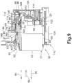
Fig. 9 is a vertical, partial cross-sectional view of the cartridge mounting portion and the ink cartridge, in which the mounting of the ink cartridge to the cartridge mounting portion is completed. -
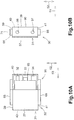
Fig. 10A is a side view of an ink cartridge, according to a modified embodiment. -
Fig. 10B is a front view of the ink cartridge ofFig. 10A . -
Fig. 11A is a side view of an ink cartridge, according to another modified embodiment. -
Fig. 11B is a front view of the ink cartridge ofFig. 11A . - Embodiments of the present invention, and their features and advantages, may be understood by referring to
Figs 1-11B , like numerals being used for like corresponding parts in the various drawings. - Referring to
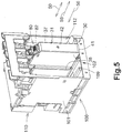
Fig. 1 , a printing apparatus, e.g., aprinter 10 is an inkjet printer configured to print an image on a sheet of printing paper by ejecting ink droplets selectively on the sheet of printing paper. Theprinter 10 comprises anink supply device 100. Theink supply device 100 comprises acartridge mounting portion 110. Thecartridge mounting portion 110 is configured to allow a printing fluid cartridge, e.g., anink cartridge 30 to be mounted therein. Thecartridge mounting portion 110 has anopening 112 and the interior of thecartridge mounting portion 110 is exposed to the exterior of thecartridge mounting portion 110 viaopening 112. Theink cartridge 30 is configured to be inserted into thecartridge mounting portion 110 via theopening 112, such that theink cartridge 30 is mounted to thecartridge mounting portion 110. Theink cartridge 30 is configured to be removed from thecartridge mounting portion 110 via theopening 112. - The
ink cartridge 30 is configured to store ink, which is used byprinter 10. Theprinter 10 comprises aprint head 21 and anink tube 20. Theink cartridge 30 and theprint head 21 are fluidically connected via theink tube 20 when theink cartridge 30 is mounted to thecartridge mounting portion 110. Theprint head 21 comprises asub tank 28. Thesub tank 28 is configured to temporarily store ink supplied via theink tube 20 from theink cartridge 30. Theprint head 21 comprisesnozzles 29 and is configured to selectively eject ink supplied from thesub tank 28 through thenozzles 29. - The
printer 10 comprises apaper feed tray 15, apaper feed roller 23, a conveyingroller pair 25, aplaten 26, adischarge roller pair 22, and adischarge tray 16. A conveyingpath 24 is formed from thepaper feed tray 15 up to thedischarge tray 16 via the conveyingroller pair 25, theplaten 26, and thedischarge roller pair 22. Thepaper feed roller 23 is configured to feed a sheet of printing paper from thepaper feed tray 15 to the conveyingpath 24. The conveyingroller pair 25 is configured to convey the sheet of printing paper fed from thepaper feed tray 15 onto theplaten 26. Theprint head 21 is configured to selectively eject ink onto the sheet of printing paper passing over theplaten 26. Accordingly, an image is printed on the sheet of printing paper. The sheet of printing paper having passed over theplaten 26 is discharged by thedischarge roller pair 22 to thepaper discharge tray 16 disposed at the most downstream side of the conveyingpath 24. - Referring to
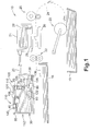
Figs. 2 to 5 , theink cartridge 30 is configured to be inserted into and removed from thecartridge mounting portion 110 in an insertion/removal direction 50, while theink cartridge 30 is in an upright position, as shown inFig. 2 , with a top face of theink cartridge 30 facing upward and a bottom face of theink cartridge 30 facing downward. The insertion/removal direction 50 extends in a horizontal direction. Theink cartridge 30 is in the upright position when theink cartridge 30 is mounted to thecartridge mounting portion 110 in the mounted position. Theink cartridge 30 is configured to be inserted into thecartridge mounting portion 110 in aninsertion direction 56 and removed from thecartridge mounting portion 110 in aremoval direction 55. The insertion/removal direction 50 is a combination of theinsertion direction 56 and theremoval direction 55. Theinsertion direction 56 extends in a horizontal direction and theremoval direction 55 extends in a horizontal direction. When theink cartridge 30 is in the upright position, a height direction (up-down direction) 52 corresponds to the gravitational direction (vertical direction). In another embodiment, the insertion/removal direction 50 may not extend exactly in a horizontal direction but may extend in a direction intersecting a horizontal direction and the gravitational direction (vertical direction). - The
ink cartridge 30 has a substantially parallelepiped shape and comprises amain body 31 and abracket 90. Themain body 31 and thebracket 90 form the exterior of theink cartridge 30. Theink cartridge 30 is a container configured to store ink therein. Theink cartridge 30 comprises anink chamber 36, which is a space formed in the interior ofink cartridge 30. More specifically, themain body 31 comprises theink chamber 36 formed therein, e.g., themain body 31 comprises aninner frame 35, and theink chamber 36 is formed in theinner frame 35. Theink cartridge 30 has a width in a width direction (left-right direction) 51, a height in the height direction (up-down direction) 52, and a depth in a depth direction (front-back direction) 53. The width direction (left-right direction) 51, the height direction (up-down direction) 52, and the depth direction (front-back direction) 53 are perpendicular to each other. The width of theink cartridge 30 is less than the height and the depth of theink cartridge 30. Whenink cartridge 30 is in the mounted position (upright position), the width direction (left-right direction) 51 is parallel with a horizontal plane, the depth direction (front-back direction) 53 is also parallel with the horizontal plane, and the height direction (up-down direction) 52 is parallel with the gravitational direction (vertical direction). When theink cartridge 30 is inserted into/removed from thecartridge mounting portion 110, the depth direction (front-back direction) 53 is parallel with the insertion/removal direction 50, and the width direction (left-right direction) 51 and the height direction (up-down direction) 52 are perpendicular to the insertion/removal direction 50. The height direction (up-down direction) 52 is parallel with an upward direction and a downward direction and is a combination of the upward direction and the downward direction. - The
ink cartridge 30 comprises afront wall 40 and arear wall 42 opposite thefront wall 40 with respect to theinsertion direction 56. Thefront wall 40 is positioned at a front side of theink cartridge 30 with respect to theinsertion direction 56 when theink cartridge 30 is inserted into thecartridge mounting portion 110. More specifically, thefront wall 40 faces in theinsertion direction 56, in other words, thefront wall 40 is oriented toward theinsertion direction 56, when theink cartridge 30 is inserted into thecartridge mounting portion 110. Therear wall 42 is positioned at a rear side of theink cartridge 30 with respect to theinsertion direction 56 when theink cartridge 30 is inserted into thecartridge mounting portion 110. More specifically, therear wall 42 faces in theremoval direction 55, in other words, therear wall 42 is oriented toward theremoval direction 55, when theink cartridge 30 is inserted into thecartridge mounting portion 110. Thefont wall 40 and therear wall 42 are aligned in depth direction (front-back direction) 53. Thefront wall 40 and therear wall 42 are aligned in the insertion/removal direction 50 when theink cartridge 30 is inserted into thecartridge mounting portion 110. Theink cartridge 30 comprisesside walls removal direction 50 and connected to thefront wall 40 and therear wall 42. Theside walls ink cartridge 30 comprises atop wall 39 connected to upper ends of thefront wall 40, therear wall 42, and theside walls ink cartridge 30 comprises abottom wall 41 connected to lower ends of thefront wall 40, therear wall 42, and theside walls top wall 39 and thebottom wall 41 are aligned in the height direction (up-down direction) 52. An outer face of thefront wall 40 is a front face of theink cartridge 30, and an outer face of therear wall 42 is a rear face of theink cartridge 30. Therefore, the front face of theink cartridge 30 is oriented toward theinsertion direction 56 when theink cartridge 30 is inserted into thecartridge mounting portion 110 in the upright position, and the rear face of theink cartridge 30 is oriented toward theremoval direction 55 when theink cartridge 30 is inserted into thecartridge mounting portion 110 in the upright position. Moreover, the front face of theink cartridge 30 is oriented to, or faces, an end face of thecartridge mounting portion 110, as can be seen fromFigs. 7 though 9, the end face forming the right end side thereof in these figures. An outer face of thetop wall 39 is a top face of theink cartridge 30, and an outer face of thebottom wall 31 is a bottom face of theink cartridge 30. Therefore, the top face of theink cartridge 30 is oriented in the upward direction when theink cartridge 30 is inserted into thecartridge mounting portion 110 in the upright position, and the bottom face of theink cartridge 30 is oriented in the downward direction when theink cartridge 30 is mounted to thecartridge mounting portion 110 in the upright position. The top face is connected to upper ends of the front face and the rear face, and the bottom face is connected to lower ends of the front face and the rear face. Similarly, outer faces of theside walls ink cartridge 30. - In this embodiment, the
bracket 90 comprises thefront wall 40, a portion of theside wall 37, a portion of theside wall 38, a portion of thetop wall 39, and a portion of thebottom wall 41, and themain body 31 comprises therear wall 42, the other portion of theside wall 37, the other portion of theside wall 38, the other portion of thetop wall 39, and the other portion of the bottom 41. Therefore, thebracket 90 comprises the front face of theink cartridge 30, a portion of the top face of theink cartridge 30, a portion of the bottom face of theink cartridge 30, and portions of the side faces of theink cartridge 30, and themain body 31 comprises the rear face of theink cartridge 30, the other portion of the top face of theink cartridge 30, the other portion of the bottom face of theink cartridge 30, and the other portions of the side faces of theink cartridge 30. - Referring to
Figs. 2 to 4 , themain body 31 comprises adetection portion 33 at a middle portion of themain body 31 with respect to the height direction (up-down direction) 52. Thedetection portion 33 is positioned at a front-wall 40 side of themain body 31. More specifically, thedetection portion 33 is positioned at a front face of themain body 31, and the front face of themain body 31 faces in theinsertion direction 56, in other words, is oriented towards theinsertion direction 56, when theink cartridge 30 is inserted into thecartridge mounting portion 110. Thebracket 90 comprises afirst protrusion 85 which comprises a detection portion, e.g., arib 88. Thefirst protrusion 85 comprises a front end with respect to theinsertion direction 56. Therib 88 comprises a front end with respect to theinsertion direction 56. Thebracket 90 comprises asecond protrusion 86. Thesecond protrusion 86 comprises a front end with respect to theinsertion direction 56. Thebracket 90 comprises anotherdetection portion 89. Thedetection portion 33 is positioned more rearward than the front end of thefirst protrusion 85, the front end of therib 88, the front end of thesecond protrusion 86, and thedetection portion 89 with respect to theinsertion direction 56. Thedetection portion 33 has a box shape having an opening facing theink chamber 36, such that the interior of thedetection portion 36 is in fluid communication with theink chamber 36. Thedetection portion 33 comprises a pair of walls made of a translucent, e.g., transparent or semi-transparent, resin configured to allow light, e.g., visible or infrared light, traveling in a direction perpendicular to the insertion/removal direction 50 to pass therethrough. In this embodiment, the direction perpendicular to the insertion/removal direction 50 is the width direction (left-right direction) 51. Thedetection portion 33 is exposed to the exterior of theink cartridge 30 via anopening 95 formed through thebracket 90 at a front-wall 40 side of thebracket 90. When theink cartridge 30 is mounted to thecartridge mounting portion 110, an optical sensor 114 (seeFig. 6 ) emits light in the direction perpendicular to the insertion/removal direction 50. Thedetection portion 33 may allow the light which is emitted from theoptical sensor 114 and reaches thedetection portion 33 via theopening 95 to pass therethrough. - The pair of walls of the
detection portion 33 is aligned in the width direction (left-right direction) 51, and a space is formed between the pair of walls of thedetection portion 33. Ink stored in theink chamber 36 can reach this space. Referring toFig. 4 , themain body 31 comprises asensor arm 60 disposed in theink chamber 36. Thesensor arm 60 comprises anarm body 61 extending mainly in the depth direction (front-back direction) 53, anindicator 62 positioned at one end of thearm body 61, and afloat 63 positioned at the other end of thearm body 61. Theindicator 62 is positioned in the space formed between the pair of walls of thedetection portion 33. Themain body 31 comprises asupport shaft 64 extending in the width direction (left-right direction) 51, and thesensor arm 60 is supported by thesupport shaft 64, such that thesensor arm 60 can pivot about thesupport shaft 64. Thesensor arm 60 is configured to pivot based on the amount of ink stored in theink chamber 36, and therefore theindicator 62 is configured to pivot based on the amount of ink stored in theink chamber 36. Thesensor arm 60 is configured to move between an upper position and a lower position. When thesensor arm 60 is in the upper position, theindicator 62 is positioned at an upper side of thedetection portion 33 with respect to the gravitational direction (vertical direction). When thesensor arm 60 is in the lower position, theindicator 62 is positioned at a lower side of thedetection portion 33 with respect to the gravitational direction.Fig. 4 depicts thesensor arm 60 positioned in the lower position when theink chamber 36 has a predetermined amount or more of ink stored therein. - When the
ink cartridge 30 is mounted to thecartridge mounting portion 110, thedetection portion 33 is positioned between a light emitter and a light receiver of theoptical sensor 114, which are aligned in a horizontal direction (the width direction or left-right direction 51) perpendicular to the insertion/removal direction 50, and thedetection portion 33 is configured to change its state between a first state and a second state. When thedetection portion 33 is in the first state, thedetection portion 33 allows light, which is emitted from the light emitter of theoptical sensor 114 and travels in the direction (the width direction or left-right direction 51) perpendicular to the insertion/removal direction 50, to pass therethrough. When thedetection portion 33 is in the second state, thedetection portion 33 attenuates the light. More specifically, when thedetection portion 33 is in the first state and the light reaches one side of thedetection portion 33 in the direction (width direction or left-right direction 51) perpendicular to the insertion/removal direction 50, a predetermined amount or more of the light comes out of the other side of thedetection portion 33 in the direction (the width direction or left-right direction 51) perpendicular to the insertion/removal direction 50 and reaches the light receiver of theoptical sensor 114. When thedetection portion 33 is in the second state and the light reaches one side of thedetection portion 33 in the direction (the width direction or left-right direction 51) perpendicular to the insertion/removal direction 50, the amount of light coming out of the other side of thedetection portion 33 and reaching the light receiver of theoptical sensor 114 is less than the predetermined amount, e.g., zero. When thesensor arm 60 is in the in the upper position, thedetection portion 33 is in the first state to allow the light to pass therethrough. When thesensor arm 60 is in the lower position, thedetection portion 33 is in the second state to attenuate the light. The attenuation of the light is caused by theindicator 62 completely preventing the light from passing therethrough in the direction (the width direction or left-right direction 51) perpendicular to the insertion/removal direction 50, by theindicator 62 absorbing some amount of the light, by theindicator 62 deflecting the light, by theindicator 62 totally reflecting the light, and etc. As such, the amount (intensity) of the light reaching the light receiver of theoptical sensor 114 depends on the state of thedetection portion 33. By detecting the state of thedetection portion 33 with theoptical sensor 114, it is determined whether theink chamber 36 has the predetermined amount or more of ink stored therein. - In another embodiment, the
ink cartridge 30 may not comprise thesensor arm 60, and therefore theindicator 62 may not be positioned in thedetection portion 33. In such a case, when thedetection portion 33 stores ink therein, thedetection portion 33 may attenuate the light. When thedetection portion 33 does not store ink therein, thedetection portion 33 may allow the light to pass therethrough. More specifically, when thedetection portion 33 does not store ink therein and the light reaches one side of thedetection portion 33 in the direction (the width direction or left-right direction 51) perpendicular to the insertion/removal direction 50, the predetermined amount or more of the light may come out of the other side of thedetection portion 33 in the direction (the width direction or left-right direction 51) perpendicular to the insertion/removal direction 50 and reaches the light receiver of theoptical sensor 114. When thedetection portion 33 stores ink therein and the light reaches one side of thedetection portion 33 in the direction (the width direction or left-right direction 51) perpendicular to the insertion/removal direction 50, the amount of light coming out of the other side of thedetection portion 33 and reaching the light receiver of theoptical sensor 114 is less than the predetermined amount, e.g., zero. The attenuation of the light may be caused by the ink absorbing some amount of the light. In yet another embodiment, thedetection portion 33 may comprise a flexible film forming a space therein. When ink is stored in the space formed by the flexible film, the flexible film bulges. Theink cartridge 30 may comprise a pivotable lever contacting the flexible film, and the lever may attenuate the light by completely preventing the light from passing therethrough in the direction (the width direction or left-right direction 51) perpendicular to the insertion/removal direction 50, by absorbing some amount of the light, by deflecting the light, by totally reflecting the light, and etc. When the ink moves out of the space formed by the flexible film and the flexible film shrinks, the lever contacting the flexible film may move to a position in which the lever no longer attenuates the light. In still another embodiment, thedetection portion 33 comprises a prism-like structure. In such a case, when ink contacts the prism-like structure, the prism-like structure may reflect light such that the light does not reach the light receiver of theoptical sensor 114. When ink does not contact the prism-like structure, the prism-like structure may reflect light such that the light reaches the light receiver of theoptical sensor 114. - The
main body 31 has anair communication opening 32 at the front-wall 40 side of themain body 31 above thedetection portion 33. More specifically, theair communication opening 32 is positioned at the front face of themain body 31 facing in theinsertion direction 56. Theair communication opening 32 is formed through a wall defining theink chamber 36 in the depth direction (front-back direction) 53. An air layer formed in theink chamber 36 and the atmosphere outside of theink chamber 36 can be brought into fluid communication via theair communication opening 32. Theair communication opening 32 is positioned between the front portion of thebracket 90 and therear wall 42 of themain body 31. Thebracket 90 has acircular opening 96 formed through a wall of thefirst projection 85 in the depth direction (front-back direction) 53, and theair communication opening 32 is accessible via theopening 96 from the exterior of theink cartridge 30 in theremoval direction 55. - The
main body 31 comprises anair communication valve 73 configured to selectively open and close theair communication opening 32. When theair communication opening 32 is opened, the pressure in theink chamber 36 maintained in a negative pressure becomes equal to the atmospheric pressure. In another embodiment, theair communication opening 32 may not be positioned at the front-wall 40 side of themain body 31 and may be positioned anywhere as long as the interior and the exterior of theink chamber 36 can be brought into fluid communication. In yet another embodiment, theink cartridge 30 may be configured to be used in theprinter 10 with theink chamber 36 maintained in negative pressure. In such a case, theink cartridge 30 may not have theair communication opening 32. - The
main body 31 comprises a printing fluid supply portion, e.g., anink supply portion 34 at the front-wall 40 side of themain body 31 below thedetection portion 33. More specifically, theink supply portion 34 is positioned at the front face of themain body 31 facing in theinsertion direction 56. Theink supply portion 34 is positioned at a lower portion of the front face of themain body 31, i.e., at a bottom-wall 41 side of the front face of themain body 31. Thebracket 90 has acircular opening 97 formed through thefront wall 40 in the depth direction (front-back direction) 53. Theink supply portion 34 has a cylindrical shape and extends through theopening 97 of thefront wall 40 in the insertion/removal direction 50. Therefore, theink supply portion 34 is positioned at thefront wall 40. Theink supply portion 34 has anink supply opening 71 formed at the distal end of theink supply portion 34. - The
ink supply portion 34 has anink path 72 formed therein. Theink path 72 extends from theink supply opening 71 up to theink chamber 36 in the depth direction (front-back direction) 53. Themain body 31 comprises anink supply valve 70 configured to selectively open and close theink supply opening 71. When theink cartridge 30 is mounted to thecartridge mounting portion 110, anink pipe 122 provided in thecartridge mounting portion 110 is inserted through theink supply opening 71 and pushes theink supply valve 70 such that theink supply opening 71 is opened. When this occurs, ink is flows out of theink chamber 36 into theink pipe 122 via theink path 72 in theinsertion direction 56. - In another embodiment, the
ink cartridge 30 may not comprise theink supply valve 70. In such a case, theink supply opening 71 may be covered and closed by a film. When theink cartridge 30 is mounted to thecartridge mounting portion 110, theink pipe 122 may break through the film, such that theink supply opening 71 is opened. - Referring to
Figs. 3 and4 , themain body 31 comprises anengagement hook 43 at a bottom-wall 41 side and the front-wall 40 side of themain body 31. Theengagement hook 43 extends forward in the depth direction (front-back direction) 53 from a lower portion of the front face of themain body 31. The front end of theengagement hook 43 comprises two protrusions extending outward in opposite directions in the width direction (left-right direction) 51. Theengagement hook 43 has a cut-out formed therein. The cut-out is positioned at a middle portion of theengagement hook 43 with respect to the width direction (left-right direction) 51 and extends in the depth direction (front-back direction) 53. With this cut-out, theengagement hook 43 is configured to resiliently deform such that a dimension thereof in the width direction (left-right direction) 51 decreases when thebracket 90 and themain body 31 are assembled. The protrusions of the front end of theengagement hook 43 are then expanded back to normal and positioned inelongated openings bracket 90, respectively, and contact inner surfaces of the walls defining theelongated openings - The
main body 31 comprises anengagement portion 45 positioned at a top-wall 39 side of theink cartridge 30. More specifically, theengagement portion 45 is positioned at a middle portion of thetop wall 39 with respect to the depth direction (front-back direction) 53. Theengagement portion 45 extends upward from thetop wall 39 and away from theink chamber 36 and comprises anengagement surface 46 which extends in the width direction (left-right direction) 51 and the height direction (up-down direction) 52. Theengagement surface 46 faces rearward with respect to theinsertion direction 56, in other wards, faces in theremoval direction 55, when theink cartridge 30 is inserted into thecartridge mounting portion 110. In another embodiment, theengagement surface 46 may not extend vertically from thetop wall 39, but may be inclined with respect to the height direction (left-right direction) 51, and may face rearward with respect to theinsertion direction 56, in other wards, face in theremoval direction 55, when theink cartridge 30 is inserted into thecartridge mounting portion 110. When theink cartridge 30 is mounted to thecartridge mounting portion 110, theengagement surface 46 contacts anengagement member 145 of thecartridge mounting portion 110, and receives an external force. More specifically, when theink cartridge 30 is mounted to and retained in thecartridge mounting portion 110, theink cartridge 30 is pushed in theremoval direction 55, and therefore, theengagement surface 46 pushes theengagement member 145 in theremoval direction 55. As a consequence, theengagement surface 46 receives a reaction force from theengagement member 145 in theinsertion direction 56. - The
main body 31 comprises apivot member 80 positioned at an upper side of themain body 31 with respect to the height direction (up-down direction) 52 and at a rear-wall 42 side of themain body 31. More specifically, thepivot member 80 is positioned at a rear portion of thetop wall 39. Thepivot member 80 has a bent flat-plate shape and its longer dimension extends in a direction substantially parallel with the depth direction (front-back direction) 53. Thepivot member 80 comprises ashaft 83 at its bent point. The bent point is positioned at a middle portion of thepivot member 80 with respect to the depth direction (front-back direction) 53. Theshaft 83 extends in the width direction (left-right direction) 51. Theshaft 83 is supported by the other portion of themain body 31 at a position spaced away from theengagement surface 46 toward therear wall 42, such that thepivot member 80 can pivot about theshaft 83. Thepivot member 80 comprises afront end portion 81 and arear end portion 82. Thefront end portion 81 extends from theshaft 83 toward theengagement surface 46. Therear end portion 82 extends from theshaft 83 toward therear wall 42. - When no external force is applied to the
pivot member 80, thepivot member 80 is positioned, such that thefront end portion 81 is positioned farthest from thetop wall 39, i.e., thefront end portion 81 is in the upper most position relative to thetop wall 39, due to its own weight, i.e., therear end portion 82 is heavier than thefront end portion 81. When thepivot member 80 is in this position, thefront end portion 81 may extend outside beyond an upper end of any other portion of themain body 31, i.e., herein the upper end of theengagement portion 45. In another embodiment, thefront end portion 81 may not extend outside beyond the upper end of any other portion of themain body 31 and may be positioned more inside than the upper end of the other portion of themain body 31, i.e., positioned below the upper end of the other portion of themain body 31. When thefront end portion 81 is pushed down, thepivot member 80 pivots in the clockwise direction inFig. 4 against its own weight. When thepivot member 80 pivots in the clockwise direction to the extent possible, thefront end portion 81 is positioned below an upper end of theengagement surface 46. In another embodiment, thepivot member 80 may be integrally formed with the other portion of themain body 31. In yet another embodiment, thepivot member 80 may be biased by a spring in the clockwise direction. In such a case, when therear end portion 82 is pushed down, thepivot member 80 pivots in the counterclockwise direction against the biasing force of the spring. - As mentioned above, the
main body 31 comprises the portions of theside walls side walls rear wall 42 up to a middle portion of themain body 31 with respect to the depth direction (front-back direction) 53. Each of the portions of theside walls inner surface side wall 37 comprises the inclinedinner surface 47 and the portion of theside wall 38 comprises the inclinedinner surface 48. When thebracket 90 is not attached to themain body 31 before theink cartridge 30 is assembled, a front portion of theinner frame 35 defining theink chamber 36 is not covered by the portions of theside walls - The
bracket 90 is attached to themain body 31. Thebracket 90 covers a front portion of themain body 31 extending from around the innerinclined surfaces main body 31 facing in theinsertion direction 56. More specifically, thebracket 90 covers the front face of themain body 31, the side-wall 37 side of the front portion of themain body 31, the side-wall 38 side of the front portion of themain body 31, the top-wall 39 side of the front portion of themain body 31, and the bottom-wall 41 side of the front portion of themain body 31. In other words, thebracket 90 covers the front face of themain body 31, a top face, a bottom face, and side faces of the front portion of themain body 31. - As described above, the
bracket 90 comprises the portions of theside walls side walls elongated openings elongated openings wall 41 sides of the portions of theside walls elongated openings side walls elongated openings engagement hook 43 in order to provide a substantial vertical tolerance or play in that direction. The protrusions of the front end of theengagement hook 43 are positioned in theelongated openings elongated openings bracket 90 is attempted to be removed from themain body 31 by pulling thebracket 90 in the depth direction (front-back direction) 53, the protrusions of the front end of theengagement hook 43 are hooked on the inner surfaces of the walls defining theelongated openings bracket 90 cannot be removed from themain body 31. The dimension of each of the protrusions of the front end of theengagement hook 43 in the height direction (up-down direction) 52 is less than the dimension of each of theelongated openings side walls end portions wall 42 side thereof, respectively. Theend portions side walls main body 31, respectively. Theend portions inner surfaces end portions inner surfaces bracket 90 is configured to move relative to themain body 31 in the height direction (up-down direction) 52 within a range defined by the dimension of theelongated openings engagement hook 43 to slide within theelongated openings engagement hook 43 and an end of a corresponding one of theelongated openings bracket 90 can slide on themain body 31 in the height direction (up-down direction) 52. When thebracket 90 moves relative to themain body 31, theend portions bracket 90 slides on the inclinedinner surfaces inner surfaces bracket 90 moves relative to themain body 31. Thebracket 90 is supported by an upper surface of the front portion of themain body 31 from below in a normal state. - The
bracket 90 has theopening 95 formed therethrough in the width direction (left-right direction) 51. Theopening 95 is positioned at the front-wall 40 side of thebracket 90 at a middle portion of thebracket 90 with respect to the height direction (left-right direction) 52. In this embodiment, theopening 95 has a rectangular shape but can have any other suitable shape according to modified embodiments. Theopening 95 has dimensions and size corresponding to thedetection portion 33 of themain body 31 and is in a position corresponding to thedetection portion 33, such that thedetection portion 33 is exposed to the exterior of theink cartridge 30 via theopening 95 in the width direction (left-right direction) 51. A portion of thebracket 90 defining theopening 95 comprises thedetection portion 89 extending in the height direction (up-down direction) 52, and asupport portion 79 extending from the lower end of thedetection portion 89 in the depth direction (front-back direction) 53 toward themain body 31 and configured to support thedetection portion 33 from below. When thebracket 90 is supported by the upper surface of the front portion of themain body 31 from below, there is a space between thedetection portion 33 and thesupport portion 79. When thebracket 90 moves in the upward direction relative to themain body 31, thesupport portion 79 contacts a lower end of thedetection portion 33. The range within which thebracket 90 moves relative to themain body 31 in the height direction (up-down direction) 52 can be defined by the dimension of theelongated openings engagement hook 43 to slide within theelongated openings detection portion 33 and thesupport portion 79 formed when thebracket 90 is supported by the upper surface of the front portion of themain body 31 from below. - The
bracket 90 has theopening 96 formed through a wall of thefirst protrusion 85 in the depth direction (front-back direction) 53, and theopening 96 is positioned at an upper protrusion, i.e. thefirst protrusion 85 with respect to theheight direction 52. In this embodiment, theopening 96 has a circular shape but any other shapes are possible as well according to modified embodiments. Theopening 96 has a dimension and size corresponding to theair communication opening 32 of themain body 31 and is in a position corresponding to theair communication opening 32, such that theair communication opening 32 is accessible via theopening 96 from the exterior of theink cartridge 30 in theremoval direction 55. - The
bracket 90 has theopening 97 formed through thefront wall 40 in the depth direction (front-back direction) 53, and theopening 97 is positioned at a lower portion of thefront wall 40 with respect to theheight direction 52. In this embodiment, theopening 97 has a circular shape but any other shapes are possible as well according to modified embodiments. Theopening 97 has a dimension and size corresponding to theink supply portion 34 of themain body 31 and is in a position corresponding to theink supply portion 34, such that theink supply portion 34 extends through theopening 37 in the depth direction (front-back direction) 53. - The
bracket 90 comprises thefirst protrusion 85 and thesecond protrusion 86 at thefront wall 40. Thefirst protrusion 85 extends from the upper end of thefront wall 40 in theinsertion direction 56 away from therear wall 42. The width of thefirst protrusion 85 in the width direction (left-right direction) 51 is the same as the width of thefront wall 40 in the width direction (left-right direction) 51. In another embodiment, the width offirst protrusion 85 may be less than the width of thefront wall 40. The front end of thefirst protrusion 85 is positioned more forward than theink supply opening 71 formed at the distal end of theink supply portion 34 in theinsertion direction 56 away from therear wall 42. Thefirst protrusion 85 has a recess, e.g., agroove 87 formed in a middle portion of thefirst protrusion 85 with respect to the width direction (left-right direction) 52. Thegroove 87 extends in the depth direction (front-back direction) 53. Thegroove 87 is opened forward in theinsertion direction 56 and opened upward in the height direction (up-down direction) 52. Both sides of thegroove 87 with respect to the width direction (left-right direction) 51 are defined and closed by a pair of surfaces of the first protrusion 85 (side walls of groove 87), and the bottom ofgroove 87 is defined and closed by a surface of thefirst protrusion 85. The cross section of thegroove 87 taken along the height direction (up-down direction) 52 and the width direction (left-right direction) 51 is rectangular but other cross sections are possible as well according to modified embodiments. - The
first protrusion 85 comprises therib 88 disposed in a middle portion of thegroove 87 with respect to the width direction (left-right direction) 51. Therib 88 extends in the depth direction (front-back direction) 53 and the height direction (up-down direction) 52. Therib 88 extends in the upward direction from the surface of thefirst protrusion 85 defining the bottom of thegroove 87. Therib 88 extends from the front-wall 40 of theink cartridge 30 in thedepth direction 53 orinsertion direction 56. Therib 88 is positioned at or adjacent to a boundary between thetop wall 39 and thefront wall 40. Each of side surfaces of therib 88 with respect to the width direction (left-right direction) 51 extends in the depth direction (front-back direction) 53 and the height direction (up-down direction) 52 in parallel with the pair of surfaces of thefirst protrusion 85 defining the both sides of thegroove 87 with respect to the width direction (left-right direction) 51. The surfaces of thefirst protrusion 85 defining the both sides of thegroove 87 with respect to the width direction (left-right direction) 51 are opposed to the side surfaces of therib 88 in the width direction (left-right direction) 52, respectively. Therib 88 is configured to attenuate light, e.g., visible or infrared light, traveling in a direction perpendicular to the insertion/removal direction 50. In this embodiment, the direction perpendicular to the insertion/removal direction 50 is the width direction (left-right direction) 51. More specifically, when theink cartridge 30 is mounted to thecartridge mounting portion 110, therib 88 is positioned between a light emitter and a light receiver of anoptical sensor 116, which are aligned in a horizontal direction (the width direction or left-right direction 51) perpendicular to the insertion/removal direction 50. Therib 88 is configured to attenuate light, which is emitted from the light emitter of theoptical sensor 116 and travels in the direction (the width direction or left-right direction 51) perpendicular to the insertion/removal direction 50. When the light reaches one side of therib 88 in the direction (the width direction or left-right direction 51) perpendicular to the insertion/removal direction 50, the amount of light coming out of the other side of therib 88 and reaching the light receiver of theoptical sensor 116 is less than a predetermined amount, e.g., zero. In other words, therib 88 is configured to attenuate the amount or the intensity of light to a level sufficient to be detected by theoptical sensor 116. The attenuation of the light is caused by therib 88 completely preventing the light from passing therethrough in the direction (the width direction or left-right direction 51) perpendicular to the insertion/removal direction 50, by therib 88 absorbing some amount of the light, by therib 88 deflecting the light, by therib 88 totally reflecting the light, and etc. As such, therib 88 can be detected by theoptical sensor 116. The dimension of therib 88 from thefront wall 40 up to the front end of therib 88 in theinsertion direction 56 away from therear wall 42 varies from one type of theink cartridge 30 to another type of theink cartridge 30. Different types of theink cartridges 30 may comprise different colors of ink, different ingredients of ink such as dye and pigment, different initial amounts of ink stored in theink chamber 36, and etc. - In another embodiment, the
first protrusion 85 may have arecess 87 formed therein. Therecess 87 may be opened forward in theinsertion direction 56, opened upward in the height direction (up-down direction) 52, and opened on one side or the both sides of thefirst protrusion 85 in the width direction (left-right direction) 51, i.e. at least one of the side walls of thegroove 87 may be omitted. When the both side walls of thegroove 87 are omitted, therib 88 is solely protruding from the platform provided by thefirst protrusion 85. In this modified embodiment and the embodiment described above, therib 88 may also acquire a guiding function with respect to any movable parts provided in thecartridge mounting portion 110, which function might be provided also by the side walls of thegroove 87 in the embodiment detailed above. - The
second protrusion 86 extends from the lower end of thefront wall 40 in theinsertion direction 56 away from therear wall 42. Thesecond protrusion 86 is positioned below theink supply portion 34. The width of thesecond protrusion 86 in the width direction (left-right direction) 51 is the same as the width of thefront wall 40 in the width direction (left-right direction) 51. In another embodiment, the width ofsecond protrusion 86 may be less than the width of thefront wall 40. The front end of thesecond protrusion 86 is positioned more forward than theink supply opening 71 formed at the distal end of theink supply portion 34 in theinsertion direction 56 away from therear wall 42. The dimension of thesecond protrusion 86 from thefront wall 40 up to the front end of thesecond protrusion 86 in theinsertion direction 56 away from therear wall 42 varies from one type of theink cartridge 30 to another type of theink cartridge 30. Different types of theink cartridges 30 may comprise different colors of ink, different ingredients of ink such as dye and pigment, different initial amounts of ink stored in theink chamber 36, and etc. In this embodiment, thesecond protrusion 86 is indirectly detected by an optical sensor 117 (seeFig. 1 ). In another embodiment, thesecond protrusion 86 may be directly detected by theoptical sensor 117. - The
bracket 90 comprises thedetection portion 89 at or adjacent to thefront wall 40 between thefirst protrusion 85 and thesecond protrusion 86 with respect to the height direction (up-down direction) 52. Thedetection portion 89 is positioned more forward than thedetection portion 33 in theinsertion direction 56 away from therear wall 42. Thedetection portion 33 and thedetection portion 89 are aligned in theinsertion direction 56. The width of thedetection portion 89 in the width direction (left-right direction) 51 is the same as the width of thedetection portion 33 in the width direction (left-right direction) 51, but other larger or smaller widths are possible as well according to modified embodiments. Thedetection portion 89 is configured to attenuate light, e.g., visible or infrared light, traveling in the direction (the width direction or left-right direction 51) perpendicular to the insertion/removal direction 50 to pass therethrough. More specifically, during mounting of theink cartridge 30 to thecartridge mounting portion 110, thedetection portion 89 passes between the light emitter and the light receiver of theoptical sensor 114. When this occurs, thedetection portion 89 attenuates light, which is emitted from the light emitter of theoptical sensor 114 and travels in the direction (the width direction or left-right direction 51) perpendicular to the insertion/removal direction 50. When the light reaches one side of thedetection portion 89 in the direction (the width direction or left-right direction 51) perpendicular to the insertion/removal direction 50, the amount of light coming out of the other side of thedetection portion 89 and reaching the light receiver of theoptical sensor 114 is less than the predetermined amount, e.g., zero. In other words, thedetection portion 89 is configured to attenuate the amount or the intensity of light to a level sufficient to be detected by theoptical sensor 114. The attenuation of the light is caused by thedetection portion 89 completely preventing the light from passing therethrough in the direction (the width direction or left-right direction 51) perpendicular to the insertion/removal direction 50, by thedetection portion 89 absorbing some amount of the light, by thedetection portion 89 deflecting the light, by thedetection portion 89 totally reflecting the light, and etc. As such, thedetection portion 89 can be detected by theoptical sensor 114. - There is a gap between the
detection portion 89 and thedetection portion 33 in the depth direction (front-back direction) 53. During mounting of theink cartridge 30 to thecartridge mounting portion 110, the light, which is emitted from the light emitter of theoptical sensor 114 and travels in the direction (the width direction or left-right direction 51) perpendicular to the insertion/removal direction 50, passes through the gap and reaches the light receiver of theoptical sensor 114. The amount of light coming out of the gap and reaching the light receiver of theoptical sensor 114 is greater than or equal to the predetermined amount. The dimension of thedetection portion 89 in the depth direction (front-back direction) 53 varies from one type of theink cartridge 30 to another type of theink cartridge 30. Different types of theink cartridges 30 may comprise different colors of ink, different ingredients of ink such as dye and pigment, different initial amounts of ink stored in theink chamber 36, and etc. - The front end of the
first protrusion 85, the front end of thesecond protrusion 86, and thedetection portion 89 are positioned more forward than thedetection portion 33 with respect to theinsertion direction 56. In other words, thedetection portion 33 is positioned more rearward than the front end of thefirst protrusion 85, the front end of thesecond protrusion 86, and thedetection portion 89 with respect to theinsertion direction 56. Each of thedetection portion 33 and theink supply opening 71 is positioned between thefirst protrusion 85 and thesecond protrusion 86 with respect to theheight direction 52. - The
ink cartridge 30 comprises aguide portion 65 at thetop wall 39. Theguide portion 65 is a pair of ribs extending upward from thetop wall 39 and extending in the depth direction (front-back direction) 53. Theguide portion 65 extends over thebracket 90 and themain body 31. The width of theguide portion 65 between the outer surfaces of the ribs in the width direction (left-right direction) is less than the width of theink cartridge 30 between the outer surfaces of theside walls main body 31 and thebracket 90 in the width direction (left-right direction). The inner gap of theguide portion 65 between the inner surfaces of the ribs in the width direction (left-right direction) is greater than the width of theengagement member 145 in the width direction (left-right direction). Theguide portion 65 comprises a front end in theinsertion direction 56. Theguide portion 65 is positioned between thegroove 87 of thefirst protrusion 85 and therear wall 42. More specifically, theguide portion 65 is positioned in the rear of thegroove 87 with respect to theinsertion direction 56. - The
ink cartridge 30 comprises aguide portion 66 at thebottom wall 41. Theguide portion 66 is a protrusion extending downward from thebottom wall 41 and extending in the depth direction (front-back direction) 53. Theguide portion 66 extends over thebracket 90 and themain body 31. The width of theguide portion 66 between the outer surfaces of theguide portion 66 in the width direction (left-right direction) is less than the width of theink cartridge 30 between the outer surfaces of theside walls main body 31 and thebracket 90 in the width direction (left-right direction). When theink cartridge 30 is inserted into and removed from thecartridge mounting portion 110, theguide portions guide grooves 109 of thecartridge mounting portion 110. - The
ink cartridge 30 comprises anIC board 74 disposed at thebracket 90 between the pair of ribs of theguide portion 65. TheIC board 74 is positioned between thegroove 87 of thefirst protrusion 85 and therear wall 42 and between theengagement portion 45 and thefront wall 40. TheIC board 74 is positioned at the top-wall 39 side of theink cartridge 30 between thefront wall 40 and therear wall 42. TheIC board 74 is positioned more rearward than thefront wall 40 and thegroove 87 with respect to theinsertion direction 56. TheIC board 74 and theink supply opening 71 are mutually shifted with respect to theinsertion direction 56. More specifically, theIC board 74 is positioned more rearward than theink supply opening 71 with respect to theinsertion direction 56. - The
bracket 90 comprises aplatform 67 on which theIC board 74 is disposed. Theplatform 67 is positioned between the pair of ribs of theguide portion 65. Theplatform 67 is a planar surface extending in the width direction (left-right direction) 51 and the depth direction (front-back direction) 53, and extending in the insertion/removal direction 50 when theink cartridge 30 is in the mounted position (upright position). A plane on which theplatform 67 extends, i.e., a plane extending in the depth direction (front-back direction) 53 and the width direction (left-right direction) 51, intersects a plane on which theengagement surface 46 extends, i.e., a plane extending in the height direction (up-down direction) 52 and the width direction (left-right direction) 51. In this embodiment, the plane on which the platform extends is perpendicular to the plane on which theengagement surface 46 extends. TheIC board 74 comprises a substantially planar upper surface extending in the width direction (left-right direction) 51 and the depth direction (front-back direction) 53. When theink cartridge 30 is in the mounted position (upright position), the upper surface of theIC board 74 extends horizontally and faces upward. A plane on which the upper surface of theIC board 74 extends, i.e., a plane extending in the depth direction (front-back direction) 53 and the width direction (left-right direction) 51, intersects the plane on which theengagement surface 46 extends, i.e., a plane extending in the height direction (up-down direction) 52 and the width direction (left-right direction) 51. In this embodiment, the plane on which the upper surface of theIC board 74 extends is perpendicular to the plane on which theengagement surface 46 extends. Because theplatform 67 is positioned more forward than theengagement surface 46 with respect to theinsertion direction 56, theIC board 74 is positioned more forward than theengagement surface 46 with respect to theinsertion direction 56. TheIC board 74 is positioned above (higher than) therib 88 and thegroove 87 of thefirst protrusion 85 with respect to the height direction (up-down direction) 52. In other words, theIC board 74 is positioned more outside - with respect to the vertical direction or the height direction (52) - than therib 88 and thegroove 87. TheIC board 74 is positioned above (higher than) at least a portion of theengagement portion 45 with respect to the height direction (up-down direction) 52. In other words, theIC board 74 is positioned more outside - with respect to the vertical direction or the height direction (52) - than at least a portion of theengagement portion 45. Thecartridge mounting portion 110 comprises threecontacts 106 aligned in the direction (width direction or left-right direction 51) perpendicular to the insertion/removal direction 50. During mounting of theink cartridge 30 to thecartridge mounting portion 110, theIC board 74 contacts and is electrically connected to the three contacts 106 (seeFig. 6 ). When the mounting of theink cartridge 30 to thecartridge mounting portion 110 is completed, theIC board 74 still contacts and is electrically connected to the threecontacts 106. - Referring to
Figs. 2 and3 , theIC board 74 comprises an IC (not shown), and electrical interfaces, e.g., a HOT electrode 75, a GND electrode 76, and asignal electrode 77. The IC is a semiconductor integrated circuit and stores data about the information of theink cartridge 30, e.g., the lot number of theink cartridge 30, the manufacturing date of theink cartridge 30, the color of ink stored in theink cartridge 30, and etc. When theink cartridge 30 is mounted to thecartridge mounting portion 110, the data stored in the IC can be read out by theprinter 10. - Each of the HOT electrode 75, the GND electrode 76, and the
signal electrode 77 is electrically connected to the IC. Each of the HOT electrode 75, the GND electrode 76, and thesignal electrode 77 extends in the depth direction (front-back direction) 53. The HOT electrode 75, the GND electrode 76, and thesignal electrode 77 are aligned and spaced apart from each other in the width direction (left-right direction) 51. The GND electrode 76 is positioned between the HOT electrode 75 and thesignal electrode 77. TheIC board 74 has a width in the width direction (left-right direction) 51 and therib 88 of thefirst protrusion 85 has a width in the width direction (left-right direction) 51, and the width of theIC board 74 is greater than the width of therib 88. Each of the HOT electrode 75, the GND electrode 76, and thesignal electrode 77 has a width in the width direction (left-right direction) 51, and the width of each of the HOT electrode 75, the GND electrode 76, and thesignal electrode 77 is greater than the width of therib 88. The center of theIC board 74 in the width direction (left-right direction) 51 and the center of therib 88 of thefirst protrusion 85 in the width direction (left-right direction) is positioned on a plane which is parallel with the height direction (up-down direction) 52 and the depth direction (front-back direction) 53. Therefore, theIC board 74 and therib 88 intersect the plane which is parallel with the height direction (up-down direction) 52 and the depth direction (front-back direction) 53. In other words, theIC board 74 and therib 88 are not offset in the width direction (left-right direction) 51. More specifically, the center of the GND electrode 76 in the width direction (left-right direction) 51 and the center of therib 88 is positioned on the plane which is parallel with the height direction (up-down direction) 52 and the depth direction (front-back direction) 53. In other words, the center of the GND electrode 76 in the width direction (left-right direction) 51 and the center of therib 88 are not offset in the width direction (left-right direction) 51. Therefore, the GND electrode 76 and therib 88 intersect the plane which is parallel with the height direction (up-down direction) 52 and the depth direction (front-back direction) 53. In other words, the GND electrode 76 and therib 86 are not offset in the width direction (left-right direction) 51. The HOT electrode 75, the GND electrode 76, thesignal electrode 77, and therib 88 are symmetrically arranged with respect to the plane which is parallel with the height direction (up-down direction) 52 and the depth direction (front-back direction) 53. Theengagement surface 46, theIC board 74, and thegroove 87 intersect the plane which is parallel with the height direction (up-down direction) 52 and the depth direction (front-back direction) 53. In other words, theengagement surface 46, theIC board 74, and thegroove 87 are not offset in the width direction (left-right direction) 51. More specifically, theengagement surface 46, the GND electrode 76, and thegroove 87 intersect the plane which is parallel with the height direction (up-down direction) 52 and the depth direction (front-back direction) 53, theengagement surface 46, the HOT electrode 75, and thegroove 87 intersect another plane which is parallel with the height direction (up-down direction) 52 and the depth direction (front-back direction) 53, and theengagement surface 46, thesignal electrode 77, and thegroove 87 intersect yet another plane which is parallel with the height direction (up-down direction) 52 and the depth direction (front-back direction) 53. In other words, theengagement surface 46, each one of the HOT electrode 75, the GND electrode 76, and thesignal electrode 77, and thegroove 87 are not offset in the width direction (left-right direction) 51. During mounting of theink cartridge 30 to thecartridge mounting portion 110, the HOT electrode 75, the GND electrode 76, and thesignal electrode 77 contact and are electrically connected to the three contacts 106 (seeFig. 6 ), respectively. When the mounting of theink cartridge 30 to thecartridge mounting portion 110 is completed, the HOT electrode 75, the GND electrode 76, and thesignal electrode 77 still contact and are electrically connected to the threecontacts 106, respectively. - The
engagement surface 46, theIC board 74, and thegroove 87 are exposed upward with respect to theheight direction 52 to the exterior of theink cartridge 30 at the top-wall 39 side of theink cartridge 30. The HOT electrode 75, the GND electrode 76, and thesignal electrode 77 are exposed upward to the exterior of theink cartridge 30 at the upper surface of theIC board 74, such that the HOT electrode 75, the GND electrode 76, and thesignal electrode 77 are accessible from above when theink cartridge 30 is in the mounted position. In other words, the HOT electrode 75, the GND electrode 76, and thesignal electrode 77 are accessible in the downward direction which is perpendicular to the width direction (left-right direction) 51 and the insertion/removal direction 50. Theengagement surface 46 is accessible from above when theink cartridge 30 is in the mounted position. In other words, theengagement surface 46 is accessible in the downward direction which is perpendicular to the width direction (left-right direction) 51 and the insertion/removal direction 50. - The pair of ribs of the
guide portion 65 extends beyond theIC board 74 upward and forward in theinsertion direction 56. In other words, the pair of ribs of theguide portion 65 extend outward beyond theIC board 74. Thebracket 90 comprises aramp 49 connecting the pair of ribs of theguide portion 65. Theramp 49 is positioned between thegroove 87 of thefirst protrusion 85 and therear wall 42 and between theIC board 74 and thefront wall 40. Theramp 49 is positioned between thegroove 87 of the first protrusion 85 (i.e., the upper end of the front wall 40) and theIC board 74. Theramp 49 is inclined downward with respect to theinsertion direction 56, such that a front portion of theramp 49 is positioned lower than a rear portion of theramp 49. When theink cartridge 30 is inserted into and/or removed from thecartridge mounting portion 110, theengagement member 145 slides on theramp 49. - A
recess 78 is formed between theengagement portion 45 and thebracket 90 at a boundary between theengagement portion 45 and thebracket 90 at an upper portion of theink cartridge 30. When themain body 31 and thebracket 90 are positioned relative to thecartridge mounting portion 110, respectively, as described below, there is no level difference between theengagement portion 45 and thebracket 90 in the height direction (up-down direction) 50 on both sides of therecess 78. Therefore, when theink cartridge 30 is inserted into or removed from thecartridge mounting portion 110, theengagement member 145 is not caught in therecess 78. - In this embodiment, the
bracket 90 covers the front face of themain body 31, the side-wall 37 side of the front portion of themain body 31, the side-wall 38 side of the front portion of themain body 31, the top-wall 39 side of the front portion of themain body 31, and the bottom-wall 41 side of the front portion of themain body 31. However, thebracket 90 may cover the front portion of themain body 31 differently. Referring toFigs. 10A and 10B , in a modified embodiment, thebracket 90 may not cover the side-wall 37 side of the front portion of themain body 31. Referring toFigs. 11A and 11B , in another modified embodiment, thebracket 90 may not cover the bottom-wall 41 side of the front portion of themain body 31. - After the
main body 31 and thebracket 90 are assembled, theink cartridge 30 is placed with thefront wall 40 facing upward. Theink supply valve 70 and theair communication valve 73 are then pushed toward theink chamber 36, such that theink supply opening 71 and theair communication opening 32 are opened. The interior of theink chamber 36 thus becomes accessible from the exterior of theink chamber 36. Subsequently, ink is introduced into the interior of theink chamber 36 from the exterior of theink chamber 36 via theink supply opening 71 while air escapes from the interior of theink chamber 36 to the exterior of theink chamber 36 via theair communication opening 32. Theink supply valve 70 and theair communication valve 73 are then moved to their original positions, such that theink supply opening 71 and theair communication opening 32 are closed. In another embodiment, only one of theink supply valve 70 and theair communication valve 73 may be pushed toward theink chamber 36, such that the corresponding one of theink supply opening 71 and theair communication opening 32 is opened. The interior of theink chamber 36 thus becomes accessible from the exterior of theink chamber 36. Subsequently, ink is introduced into the interior of theink chamber 36 from the exterior of theink chamber 36 via theink supply opening 71 or theair communication opening 32 while air escapes from the interior of theink chamber 36 to the exterior of theink chamber 36 via theink supply opening 71 or theair communication opening 32. Because only one of theink supply opening 71 and theair communication opening 32 is opened, it may take more time to fill theink chamber 36 with ink compared to the above described method in which both theink supply opening 71 and theair communication opening 32 are opened. Theink supply valve 70 or theair communication valve 73 is then moved to its original position, such that theink supply opening 71 or theair communication opening 32 is closed. - When the
ink cartridge 30 is refilled, an opening may be formed through at least one of thefront wall 40, therear wall 42, thetop wall 39, thebottom wall 41, theside wall 37, and theside wall 38, such that the interior of theink chamber 36 becomes accessible from the exterior of theink chamber 36 via the opening. Theink supply opening 71 and/or theair communication opening 32 may be additionally opened. Subsequently, ink is introduced into the interior of theink chamber 36 from the exterior of theink chamber 36 via the opening formed through the wall of theink cartridge 30 while air escapes from the interior of theink chamber 36 to the exterior of theink chamber 36 via the opening and/or via theink supply opening 71 and/or theair communication opening 32 if opened. And then, the opening formed through the wall of theink cartridge 30 is closed by a plug, curable adhesive, a tape, etc., and theink supply opening 71 and/or theair communication opening 32 is closed if opened before. - Referring to
Fig. 1 , theprinter 10 comprises theink supply device 100. Theink supply device 100 is configured to supply ink to theprint head 21. Theink supply device 100 comprises thecartridge mounting portion 110 to which theink cartridge 30 is mountable. InFig. 1 , theink cartridge 30 is mounted to thecartridge mounting portion 110. - Referring to
Figs. 5 and6 , thecartridge mounting portion 110 comprises acase 101, and thecase 101 has theopening 112 formed through one face of thecase 101. Theink cartridge 30 is configured to be inserted into or removed from thecase 101 through theopening 112. Thecase 101 has thegroove 109 formed in a top surface defining the upper end of the inner space of thecase 101 and also has thegroove 109 formed in a bottom surface defining the lower end of the inner space of thecase 101. Thegrooves 109 extend in the insertion/removal direction 50. Theink cartridge 30 is guided in the insertion/removal direction 50 with theguide portion 65 inserted in thegroove 109 formed in the top surface of thecase 101 and theguide groove 66 inserted in thegroove 109 formed in the bottom surface of thecase 101. Thecase 101 is configured to receive fourink cartridges 30 storing cyan ink, magenta ink, yellow ink, and black ink, respectively. - The
case 101 comprises threepartition plates 102 extending in the vertical direction and the insertion/removal direction 50. The threepartition plates 102 partition the inner space of thecase 101 into four spaces. The fourink cartridges 30 are configured to be mounted in the four spaces, respectively. - Referring to
Fig. 6 , thecase 101 comprises an end surface opposite theopening 112 in the insertion/removal direction 50. Thecartridge mounting portion 110 comprises aconnection portion 103 provided at a lower portion of the end surface of thecase 101 at a position corresponding to theink supply portion 34 of theink cartridge 30 mounted to thecase 101. In this embodiment, fourconnection portions 103 are provided for the fourink cartridges 30 mountable to thecase 101. - The
connection portion 103 comprises a printing fluid supply pipe, e.g., theink pipe 122, and a holdingportion 121. Theink pipe 122 is a cylindrical pipe made of a synthetic resin. Theink pipe 122 is connected to theink tube 20 at the exterior of thecase 101. Theink tube 20 connected to theink pipe 20 extends to theprinting head 21 to supply ink to theprinting head 21. InFig. 5 and6 , theink tube 20 is not depicted. - The holding
portion 121 has a cylindrical shape. Theink pipe 122 is positioned at the center of the holdingportion 121. Referring toFig. 9 , when theink cartridge 30 is mounted to thecartridge mounting portion 110, theink supply portion 34 is inserted into the holdingportion 121. When this occurs, theink supply portion 34 is positioned relative to the holdingportion 121 with respect to the height direction (up-down direction) 52 by an outer surface of theink supply portion 34 contacting an inner surface of the holdingportion 121. When theink supply portion 34 is inserted into the holdingportion 121, theink pipe 122 is inserted into theink supply opening 71. This allows ink stored in theink chamber 36 to flow out into theink pipe 122. - Referring to
Fig. 6 , thecartridge mounting portion 110 comprises asenor unit 104 above theconnection portion 103. Thesensor unit 104 comprises aboard 113 and theoptical senor 114 mounted to theboard 113. More specifically, thesensor unit 104 comprises oneboard 113 and fouroptical sensors 114 mounted to the oneboard 113, corresponding to the fourink cartridges 30 mountable to thecase 101. - As described above, the
optical sensor 114 comprises the light emitter, e.g., a light emitting diode, and the light receiver, e.g., a photo-transistor. The light emitter and the light receiver are housed in a housing, and the housing extends from theboard 113 in the insertion/removal direction 50 toward theopening 112. The housing has substantially a U-shape when view from the above. The light emitter and the light receiver of theoptical sensor 114 are aligned in a horizontal direction (the width direction or left-right direction 51) perpendicular to the insertion/removal direction 50 with a space formed therebetween. The light emitter is configured to emit light, e.g., infrared or visible light, toward the light receiver in the horizontal direction (the width direction or left-right direction 51) perpendicular to the insertion/removal direction 50, and the light receiver is configured to receive the light emitted from the light emitter. Thedetection i portion 33 and thedetection portion 89 can be inserted into the space between the light emitter and the light receiver. Theoptical sensor 114 is configured to detect the change in the amount (intensity) of the light when thedetection portion 33 or thedetection portion 89 enters an optical path (detection point) formed between the light emitter and the light receiver. Theoptical sensor 114 is electrically connected to a controller (described later) of theprinter 10, and when theoptical sensor 114 detects thedetection portion 33 or thedetection portion 89, a signal output from theoptical sensor 114 to the controller changes. - Referring to
Fig. 6 , thecartridge mounting portion 110 comprises asenor unit 105 positioned at the top surface of thecase 101 adjacent to the end surface of thecase 101. Thesensor unit 105 comprises aboard 115 and theoptical sensor 116 mounted to theboard 115. More specifically, thesensor unit 105 comprises oneboard 115 and fouroptical sensors 116 mounted to the oneboard 115, corresponding to the fourink cartridges 30 mountable to thecase 101. - As described above, the
optical sensor 116 comprises the light emitter, e.g., a light emitting diode, and the light receiver, e.g., a photo-transistor. The light emitter and the light receiver are housed in a housing, and the housing extends from theboard 115 downward in the vertical direction. The housing has substantially an up-side-down U-Shape when viewed in the insertion/removal direction 50. - The light emitter and the light receiver of the
optical sensor 116 are aligned in the horizontal direction (the width direction or left-right direction 51) perpendicular to the insertion/removal direction 50 with a space formed therebetween. The light emitter is configured to emit light, e.g., infrared or visible light, toward the light receiver in the horizontal direction (the width direction or left-right direction 51) perpendicular to the insertion/removal direction 50, and the light receiver is configured to receive the light emitted from the light emitter. When theink cartridge 30 is mounted to thecartridge mounting portion 110, therib 88 of thefirst protrusion 85 is inserted into the space between the light emitter and the light receiver. Theoptical sensor 116 is configured to detect the change in the amount (intensity) of the light when therib 88 enters an optical path (detection point) formed between the light emitter and the light receiver. Theoptical sensor 116 is electrically connected to the controller of theprinter 10, and when theoptical sensor 116 detects therib 88, a signal output from theoptical sensor 116 to the controller changes. Based on the signal change, whether theink cartridge 30 is mounted to thecartridge mounting portion 110 can be determined by the controller. In other words, therib 88 is configured to provide information as to the presence of theink cartridge 30 in thecartridge mounting portion 110 by attenuating the light of theoptical sensor 116. - The
cartridge mounting portion 110 compriseselectrical contacts 106 positioned at the top surface of thecase 101 between the end surface of thecase 101 and theopening 112. Threecontacts 106 are provided and aligned in the direction (width direction or left-right direction 51) perpendicular to the insertion/removal direction 50. Threecontacts 106 are arranged at positions corresponding to the HOT electrode 75, the GND electrode 76, thesignal electrode 77 of theink cartridge 30. Thecontacts 106 have electrical conductivity and resiliency. Thecontacts 106 are configured to be resiliently deformed in the upward direction when these are pressed from below. Four sets of threecontacts 106 are provided, corresponding to the fourink cartridges 30 mountable to thecase 101. - The
printer 10 comprises the controller, and thecontacts 106 are electrically connected to the controller via an electrical circuit. The controller may comprise a CPU, a ROM, a RAM, and etc. When the HOT electrode 75 contacts and is electrically connected to a corresponding one of thecontacts 106, a voltage Vc is applied to the HOT electrode 75. When the GND electrode 76 contacts and is electrically connected to a corresponding one of thecontacts 106, the GND electrode 76 is grounded. When the HOT electrode 75 and the GND electrode 76 contact and are electrically connected to the correspondingcontacts 106, respectively, power is supplied to the IC. When thesignal electrode 77 contacts and is electrically connected to a corresponding one of thecontacts 106, data stored in the IC is accessible. Outputs from the electrical circuit are input to the controller. - Referring to
Fig. 1 , thecase 101 has aspace 130 formed at the lower end of the end surface of thecase 101. Thecartridge mounting portion 110 comprises aslider 135 disposed in thespace 130. Foursliders 135 are provided corresponding to the fourink cartridges 30 mountable to thecase 101. Thespace 130 is contiguous with the inner space of thecase 101. Theslider 135 is configured to move in thespace 130 in the insertion/removal direction 50. Theslider 135 has substantially a rectangular parallelepiped shape. Theslider 135 is positioned in the line of travel of thesecond protrusion 86 of theink cartridge 30 and is configured to contact thesecond protrusion 86. - The
cartridge mounting portion 110 comprises acoil spring 139 disposed in thespace 130. Thecoil spring 139 is configured to bias theslider 135 toward theopening 112, i.e., in theremoval direction 55. When thecoil spring 139 is in a normal length, i.e., when no external force is applied to theslider 135, theslider 135 is positioned at anopening 112 side of thespace 130. When theink cartridge 30 is inserted into thecase 101, thesecond protrusion 86 of theink cartridge 30 contacts theslider 135 and pushes theslider 135 in theinsertion direction 56. When this occurs, thecoil spring 139 contracts and theslider 135 slides in theinsertion direction 56. Thecoil spring 139 in a contracted state biases theink cartridge 30 in theremoval direction 55 via theslider 135. - The
cartridge mounting portion 110 comprises theoptical sensor 117 at an upper portion of thespace 130. Fouroptical sensors 117 are provided corresponding to the fourink cartridges 30 mountable to thecase 101. In other words, the fouroptical sensors 117 are provided corresponding to the foursliders 135. The fouroptical sensors 117 are aligned in the direction (width direction or left-right direction 51) perpendicular to the insertion/removal direction 50. Theoptical sensor 117 has the same structure as theoptical sensor 116. - When the
ink cartridge 30 is mounted to thecase 101, theslider 135 is pushed and inserted into a space between a light emitter and a light receiver of theoptical sensor 117. Theoptical sensor 117 is configured to detect the change in the amount (intensity) of light when theslider 135 enters an optical path (detection point) formed between the light emitter and the light receiver of theoptical sensor 117. Theoptical sensor 117 is electrically connected to the controller of theprinter 10, and when theoptical sensor 117 detects theslider 135, a signal output from theoptical sensor 117 to the controller changes. InFigs. 6 to 9 , theslider 135, thecoil spring 139, and theoptical sensor 117 are not depicted. - In the
cartridge mounting portion 110, the detection point (optical path) of theoptical sensor 114 is positioned more rearward than the detection point (optical path) of theoptical sensor 116 and the detection point (optical path) of theoptical sensor 117 in theinsertion direction 56. - Referring to
Fig. 6 , thecartridge mounting portion 110 comprises arod 125 at the end surface of thecase 101. The position of therod 125 with respect to the height direction (up-down direction) 52 corresponds to the position of theair communication valve 73 of theink cartridge 30 mounted to thecartridge mounting portion 110 with respect to the height direction (up-down direction) 52. Fourrods 125 are provided corresponding to the fourink cartridges 30 mountable to thecase 101. Therod 125 has a cylindrical shape and extends from the end surface of thecase 101 in the insertion/removal direction 50 toward theopening 112. During the mounting of theink cartridge 30 to thecartridge mounting portion 110, therod 125 is inserted through theopening 96 of thebracket 90, and the distal end of therod 125 contacts theair communication valve 73. Theair communication valve 73 is pushed by therod 125, such that theair communication opening 32 is opened. An outer surface of therod 125 contacts aninner surface 98 of thebracket 90 defining theopening 96, and thereby thebracket 90 is positioned relative to thecartridge mounting portion 110 with respect to the height direction (up-down direction) 52. - Referring to
Fig. 6 , thecartridge mounting portion 110 comprises theengagement member 145 positioned at an upper portion of thecase 101. Theengagement member 145 is configured to retain theink cartridge 30 in the mounted position. Theengagement member 145 is positioned adjacent to the upper end of theopening 112. Theengagement member 145 is positioned between theopening 112 and thecontacts 106. Each of thecontacts 106 and theengagement member 145 intersect a plane which is parallel with the insertion/removal direction 50 and the vertical (gravitational) direction. In other words, each of thecontacts 106 and theengagement member 145 are not offset in the width direction (left-right direction) 51. Fourengagement members 145 are provided corresponding to the fourink cartridges 30 mountable to thecase 101. - The
cartridge mounting portion 110 comprises ashaft 147 positioned adjacent to the upper end of theopening 112. Theshaft 147 is attached to thecase 101 and extends in the direction (width direction or left-right direction 51) perpendicular to the insertion/removal direction 50. Theshaft 147 extends through an end of theengagement member 145 adjacent to theopening 112, in other words, a rear end of theengagement member 145 with respect to theinsertion direction 56. Theengagement member 145 is supported by theshaft 147, such that theengagement member 145 can pivot about theshaft 147 selectively toward and away from the inner space of thecase 101. Theengagement member 145 comprises anengagement end 146 opposite the end of theengagement member 145 through which theshaft 147 extends. In other words, theengagement end 146 is positioned at a front end of theengagement member 145 with respect to theinsertion direction 56. Theengagement end 146 is configured to contact theengagement portion 45 of theink cartridge 30. By the contact between theengagement end 146 and theengagement surface 46 of theengagement portion 45, theink cartridge 30 is retained in the mounted position in thecase 101 against the biasing force from theslider 135. When theengagement end 146 contacts theengagement surface 46, theengagement end 146 extends substantially in the width direction (left-right direction) 51 and the height direction (up-down direction) 52. Theengagement member 145 is configured to move between a lock position and an unlock position. When theengagement member 145 is in the lock position, theengagement end 146 can contact theengagement portion 45. When theengagement member 145 is in the unlock position, theengagement end 146 cannot contact theengagement portion 45. - The
engagement member 145 comprises aslide surface 148 extending from theengagement end 146 toward theshaft 147. When theengagement end 146 contacts theengagement surface 46, theslide surface 148 extends substantially in the width direction (left-right direction) 51 and the depth direction (front-back direction) 53. Theslide surface 148 has a width in the width direction (left-right direction) 51, such that theslide surface 148 contacts and slides on all the HOT electrode 75, the GND electrode 76, and thesignal electrode 77 at the same time when theink cartridge 30 is inserted into and/or removed from thecartridge mounting portion 110. - The
engagement member 145 is configured to pivot downward due to its own weight or biased by a spring (not shown). When theink cartridge 30 is mounted to thecartridge mounting portion 110, theengagement end 146 contacting theengagement portion 45 is positioned above thefront end portion 81 of thepivot member 80. When thefront end portion 81 moves upward and pushes up theengagement end 146, theengagement member 145 pivots upward about theshaft 147 from the lock position to the unlock position. The movable range of theengagement member 145 is limited, such that theengagement member 145 does not pivot downward beyond the lock position. - Referring to
Figs. 7 to 9 , it is described how theink cartridge 30 is mounted to thecartridge mounting portion 110. InFigs. 7 to 9 , thecartridge mounting portion 110 is depicted in cross-section, but only a top-wall 39 side portion of theink cartridge 30 is depicted in cross-section. - As described above, because the
bracket 90 is supported by the upper surface of the front portion of themain body 31 from below, thebracket 90 is movable in the upward direction relative to themain body 31 before theink cartridge 30 is mounted to thecartridge mounting portion 110. Referring toFig. 7 , when theink cartridge 30 is inserted into thecartridge mounting portion 110 in theinsertion direction 56, theguide portions ink cartridge 30 are inserted into thegrooves 109 of thecase 101, and thereby theink cartridge 30 is roughly positioned relative to thecartridge mounting portion 110 with respect to the width direction (left-right direction) 51 and the height direction (up-down direction) 52. Theink cartridge 30 is configured to slide toward the end surface of thecase 101 while theguide portions grooves 109. - Referring to
Figs. 7 and8 , when theink cartridge 30 is inserted into thecase 101, the front end of thefirst protrusion 85 contacts theslide surface 148 of theengagement member 145. When theink cartridge 30 is further inserted, theslide surface 148 climbs onto thefirst protrusion 85 and theramp 49. When this occurs, theengagement member 145 pivots upward in the counterclockwise direction inFig. 7 from the lock position to the unlock position. When theink cartridge 30 is further inserted, theslide surface 148 of theengagement member 145 slides on theramp 49 and theIC board 74 and passes over therecess 78. When theslide surface 148 slides on the HOT electrode 75, the GND electrode 76, and thesignal electrode 77, dust is wiped off the HOT electrode 75, the GND electrode 76, and thesignal electrode 77. - Referring to
Fig. 1 , when theink cartridge 30 is inserted into thecase 101, thesecond protrusion 86 contacts theslider 135. When theink cartridge 30 is further inserted, theslider 135 is pushed in theinsertion direction 56 against the biasing force from thecoil spring 139 into the detection point (optical path) of theoptical sensor 117. When theoptical sensor 117 detects theslider 135, the signal output from theoptical sensor 117 to the controller changes from a HI level signal to a LOW level signal. - Referring to
Fig. 8 , after thesecond protrusion 86 starts to push theslider 135, thedetection portion 89 enters the detection point (optical path) of theoptical sensor 114. When theoptical sensor 114 detects thedetection portion 89, the signal output from theoptical sensor 114 to the controller changes from a HI level signal to a LOW level signal. - Referring to
Fig. 8 , after thedetection portion 89 enters the detection point (optical path) of theoptical sensor 114, therib 88 of thefirst protrusion 85 enters the detection point (optical path) of theoptical sensor 116. When theoptical sensor 116 detects therib 88, the signal output from theoptical sensor 116 to the controller changes from a HI level signal to a LOW level signal. After thedetection portion 89 passes the detection point (optical path) of theoptical sensor 114, the gap between thedetection portion 89 and thedetection portion 33 passes the detection point (optical path) of theoptical sensor 114. When this occurs, the signal output from theoptical sensor 114 to the controller changes from the LOW level signal to the HI level signal. And then, when thedetection portion 33 enters the detection point (optical path) of theoptical sensor 114, the signal output from theoptical sensor 114 to the controller changes from the HI level signal to the LOW level signal if thesensor arm 60 is in the lower position. - If the
detection portion 89 is longer in the depth direction (front-back direction) 53 in one type of theink cartridge 30, thedetection portion 89 is still in the detection point (optical path) of theoptical sensor 114 when therib 88 starts to enter the detection point (optical path) of theoptical sensor 116, and therefore, the signal output from theoptical sensor 114 is the LOW level signal at a time that the signal output from theoptical sensor 116 changes from the HI level signal to the LOW level signal. If thedetection portion 89 is shorter in the depth direction (front-back direction) 53 in another type of theink cartridge 30, thedetection portion 89 is no longer in the detection point (optical path) of theoptical sensor 114 when therib 88 starts to enter the detection point (optical path) of theoptical sensor 116, and therefore, the signal output from theoptical sensor 114 is the HI level signal at a time that the signal output from theoptical sensor 116 changes from the HI level signal to the LOW level signal. In other words, therib 88 and thedetection portion 89 are configured to provide information as to the type of theink cartridge 30 by attenuating the light of theoptical sensor 116 and theoptical sensor 114. - If the
second protrusion 86 is longer in the depth direction (front-back direction) 53 in one type of theink cartridge 30, theslider 135 is already in the detection point (optical path) of theoptical sensor 117 when therib 88 starts to enter the detection point (optical path) of theoptical sensor 116, and therefore, the signal output from theoptical sensor 117 is the LOW level signal at a time that the signal output from theoptical sensor 116 changes from the HI level signal to the LOW level signal. If thesecond protrusion 86 is shorter in the depth direction (front-back direction) 53 in another type of theink cartridge 30, theslider 135 is not yet in the detection point (optical path) of theoptical sensor 117 when therib 88 starts to enter the detection point (optical path) of theoptical sensor 116, and therefore, the signal output from theoptical sensor 117 is the HI level signal at a time that the signal output from theoptical sensor 116 changes from the HI level signal to the LOW level signal. In other words, therib 88 and thesecond protrusion 86 are configured to provide information as to the type of theink cartridge 30 by attenuating the light of theoptical sensor 116 and theoptical sensor 117. - Referring to
Fig. 8 , during the insertion of theink cartridge 30 into thecase 101, theink supply portion 34 of theink cartridge 30 is inserted into the holdingportion 121 and theink pipe 122 is inserted into theink supply opening 71. When this occurs, theink supply portion 34 is positioned relative to the holdingportion 121 with respect to the height direction (up-down direction) 52 by the outer surface of theink supply portion 34 contacting the inner surface of the holdingportion 121, i.e., themain body 31 is positioned relative to thecartridge mounting portion 110 with respect to the height direction (up-down direction) 52. Theink supply valve 70 is pushed by theink pipe 122, such that theink supply opening 71 is opened. Theink pipe 122 has an ink introduction opening formed in the distal end thereof, and ink stored in theink chamber 36 flows into theink pipe 122 via the ink introduction opening in theinsertion direction 56. - Referring to
Fig. 8 , during the insertion of theink cartridge 30 into thecase 101, therod 125 enters theopening 96 of thebracket 90. Thebracket 90 is movable in the upward direction relative to themain body 31. When therod 125 enters theopening 96, an upper portion of the outer surface of therod 125 contact an upper portion of theinner surface 98 of thebracket 90 defining theopening 96, and pushes up thebracket 90, such that thebracket 90 slides on themain body 31 in the upward direction. Thebracket 90 cannot move in the downward direction relative to thecartridge mounting portion 110 because the upper portion of the outer surface of therod 125 contacts the upper portion of theinner surface 98 of thebracket 90 defining the opening 96 from below. Referring toFig. 9 , therod 125 contacts and pushes theair communication valve 73. Theair communication valve 73 moves away from theair communication opening 32, such that air flows into theink chamber 36 via theair communication opening 32. - Meanwhile, referring to
Figs, 8 and9 , thecontacts 106 contact theramp 49 of thebracket 90. Because theramp 49 is inclined upward when thecontact 106 moves toward therear wall 42 of theink cartridge 30 and because thebracket 90 cannot move in the downward direction with the upper portion of the outer surface of therod 125 contacting the upper portion of theinner surface 98 of thebracket 90 defining theopening 96, thecontacts 106 are resiliently deformed in the upward direction when thecontacts 106 slides on theramp 49 and theIC board 74. The resiliently-deformedcontacts 106 bias theIC board 74 in the downward direction. When thecontacts 106 reach theIC board 74, thebracket 90 is positioned relative to thecartridge mounting portion 110 with respect to the height direction (up-down direction) 52 by thecontacts 106 androd 125 sandwiching thebracket 90 from above and from below, respectively. - When the
ink cartridge 30 is further inserted toward the end surface of thecase 101, referring toFig. 9 , thecontacts 106 contact and are electrically connected to the HOT electrode 75, the GND electrode 76, thesignal electrode 77 of theIC board 74, respectively. When the mounting of theink cartridge 30 reaches the mounted position, the HOT electrode 75, the GND electrode 76, and thesignal electrode 77 still contact and are electrically connected to the threecontacts 106, respectively. - When the
ink cartridge 30 reaches the mounted position, theengagement surface 46 of theengagement portion 45 of theink cartridge 30 has passed theengagement end 146 of theengagement member 145 in theinsertion direction 56. Theengagement member 145 pivots in the clockwise direction inFig. 9 to the lock position, and theengagement end 146 contacts theengagement surface 46. With this contact between theengagement member 145 and theengagement portion 45, theink cartridge 30 is retained in the mounted position against the biasing force from thecoil spring 139. In other words, theink cartridge 30 is positioned relative to thecartridge mounting portion 110 with respect to the insertion/removal direction 50. As such, the mounting of theink cartridge 30 to thecartridge mounting portion 110 is completed. - When the
ink cartridge 30 is in the mounted position in thecartridge mounting portion 110, themain body 31 is positioned with theink supply portion 34 inserted into the holdingportion 121 and theink pipe 122 inserted into theink supply opening 71, and thebracket 90 is positioned sandwiched by thecontacts 106 and therod 125 in a position between the ends of its movable range. - When the
ink cartridge 30 is in the mounted position in thecartridge mounting portion 110, thefront end portion 81 of thepivot member 80 is positioned below theengagement end 146 of theengagement member 145. Therear end portion 82 of thepivot member 80 is positioned away from thetop wall 39. - Based on the level of the output signal from the
optical sensor 116, whether theink cartridge 30 is mounted to thecartridge mounting portion 110 is determined by the controller. In other words, therib 88 is configured to provide information as to the presence of theink cartridge 30 in thecartridge mounting portion 110 by attenuating the light of theoptical sensor 116. Based on the level of the output signal from theoptical sensor 114 and/or based on the level of the output signal from theoptical sensor 117 at the time that the signal output from theoptical sensor 116 changes from the HI level signal to the LOW level signal, the type of theink cartridge 30 is determined by the controller. In other words, therib 88, and thedetection portion 89 or thesecond protrusion 86 are configured to provide information as to the type of theink cartridge 30 by attenuating the light of theoptical sensor 116 and theoptical sensor 114 or theoptical sensor 117. By periodically checking the level of the output signal from theoptical sensor 114, the amount of ink stored in theink chamber 36 is determined by the controller, i.e., whether theink chamber 36 has the predetermined amount or more of ink stored therein is determined. In other words, thedetection portion 33 is configured to indicate the presence or absence of ink within theink chamber 36 by attenuating or not attenuating the light of theoptical sensor 114. Based on the data read out from theIC board 74, the information of theink cartridge 30, e.g., the lot number of theink cartridge 30, the manufacturing date of theink cartridge 30, the color of ink stored in theink cartridge 30, and etc. is determined. - In another embodiment, the
bracket 90 may be movable in the downward direction relative to themain body 31 in the initial position before theink cartridge 30 is mounted to thecartridge mounting portion 110. In such a case, thebracket 90 is supported by static friction between theend portions bracket 90 and the inclinedinner surfaces main body 31. When theink cartridge 30 is inserted into thecase 101 and therod 125 is inserted into theopening 96 of thebracket 90, the outer surface of therod 125 may not contact theinner surface 98 of thebracket 90 defining theopening 96 initially. When theink cartridge 30 is further inserted, thecontacts 106 contact theramp 49 and theIC board 74 and push down thebracket 90, such that the upper portion of the outer surface of therod 125 contacts the upper portion of theinner surface 98 of thebracket 90 defining theopening 96. When thecontacts 106 reach theIC board 74, thebracket 90 is positioned relative to thecartridge mounting portion 110 with respect to the height direction (up-down direction) 52 by thecontacts 106 androd 125 sandwiching thebracket 90 from above and from below, respectively. - The time profile of the evens which occur during the insertion of the
ink cartridge 30 to thecartridge mounting portion 110 is described in more detail here. When the insertion is started, theslide surface 148 of theengagement portion 145 starts to slide on theIC board 74. Thesecond protrusion 86 then contacts theslider 135 and starts to push theslider 135. Thedetection portion 89 then starts to enter the detection point (optical path) of theoptical sensor 114. Therib 88 then starts to enter the detection point (optical path) of theoptical sensor 116. Therod 125 then contacts theair communication valve 73 and starts to push theair communication valve 73. Thecontacts 106 then starts to contact theIC board 74. The gap between thedetection portion 89 and thedetection portion 33 then starts to enter the detection point (optical path) of theoptical sensor 114. Theink pike 122 then contacts theink supply valve 70 and starts to push theink supply valve 70. Thedetection portion 33 then starts to enter the detection point (optical path) of theoptical sensor 114. Theengagement end 146 then contacts theengagement surface 46. - After the mounting of the
ink cartridge 30 to thecartridge mounting portion 110 is completed. Theprinter 10 starts printing. When the ink stored in theink chamber 36 is used up by theprinter 10, the usedink cartridge 30 is removed from thecartridge mounting portion 110, and anew ink cartridge 30 is mounted to thecartridge mounting portion 110. - When the
ink cartridge 30 is intended to be removed from thecartridge mounting portion 110, therear end portion 82 of thepivot member 80 is pushed down by a user. Accordingly, thefront end portion 81 of thepivot member 80 moves up and separates from thetop wall 39. When this occurs, theengagement member 145 is pushed up by thefront end portion 81 of thepivot member 80, and theengagement end 146 of theengagement member 145 moves to a position above theengagement surface 46, i.e., to a position separated from theengagement surface 46. As such, theengagement member 145 moves from the lock position to the unlock position, and theink cartridge 30 is released from the state held by theengagement member 145. - When the
engagement end 146 separates away from theengagement surface 46, an external force applied to theink cartridge 30 e.g., the biasing force of thecoil spring 139 moves theink cartridge 30 in theremoval direction 55. Nevertheless, because a finger of the user still contacts the pushed-downrear end portion 82 of thepivot member 80, theink cartridge 30 moving in theremoval direction 55 is stopped by the user. The biasing force of thecoil spring 139 is received by the user's finger via thepivot member 80. - When the user moves his/her finger in the
removal direction 55, theink cartridge 30 moves following the finger, pushed by theslider 135 and thecoil spring 139. When this occurs, theIC board 74 disposed on thebracket 90 is released from the downward biasing force of thecontacts 106 of thecartridge mounting portion 110. While theink cartridge 30 moves in theremoval direction 55 following the user's finger, theslide surface 148 of theengagement member 145 passes over therecess 78 and slides on theIC board 74 and theramp 49. When theslide surface 148 slides on the HOT electrode 75, the GND electrode 76, and thesignal electrode 77, dust is wiped off the HOT electrode 75, the GND electrode 76, and thesignal electrode 77. After sliding on theramp 49, theslide surface 148 passes over thegroove 87. When this occurs, the dust wiped off by theslide surface 148 falls into thegroove 87. Accordingly, a likelihood that the dust falls down and adheres to a portion of theink supply portion 34 surrounding theink supply opening 71 is reduced. - Meanwhile, the outer surface of the
rod 125 separates away from theinner surface 98 of thebracket 90 defining theopening 96, such that thebracket 90 moves down relative to themain body 31 to the initial position in which thebracket 90 is supported by the upper surface of the front portion of themain body 31. Theink pipe 122 is pulled out of theink supply portion 34. As such, theink cartridge 30 is removed from thecartridge mounting portion 110. - In this embodiment, because the
ink cartridge 30 comprises thedetection portion 89 and therib 88 configured to be detected by theoptical sensors IC board 74, even if the electrical connection between theIC board 74 and thecontacts 106 fails to be established or the data fails to be read out from the IC via thesignal electrode 77, it can be determined that theink cartridge 30 is mounted to theprinter 10 based on the information obtained from thedetection portion 89 and therib 88. Therefore , theink cartridge 30 can be used even if the electrical connection between theIC board 74 and thecontacts 106 fails to be established or the data fails to be read out from the IC via thesignal electrode 77. - In this embodiment, because the light emitted from the
optical sensor insertion direction 50, thedetection portion 89 and therib 88 can enter the detection point (optical path) of theoptical sensor insertion direction 50 at desired timings. Moreover, because the HOT electrode 75, the GND electrode 76, and thesignal electrode 77 are accessible in the downward direction perpendicular to theinsertion direction 50 and the direction in which the light travels, even if the HOT electrode 75, the GND electrode 76, and thesignal electrode 77 are accessed by thecontacts 106 in the downward direction, such that theink cartridge 30, or parts thereof, is displaced in the downward direction, such displacement does not affect the timings of thedetection portion 89 and therib 88 entering the detection point (optical path) of theoptical sensor insertion direction 56. This is because the timings are determined by the movement of theink cartridge 30 in theinsertion direction 56, and not determined by the downward displacement of theink cartridge 30. Generally speaking, when events occur in directions perpendicular to each other, such events can be independent events and cannot be mutually affected. - In this embodiment, because the HOT electrode 75, the GND electrode 76, and the
signal electrode 77 are positioned between thefront wall 40 and therear wall 42, the biasing force from theslider 135 and thecoil spring 139 in theremoval direction 55 is not directly received by the HOT electrode 75, the GND electrode 76, and thesignal electrode 77. Therefore, a likelihood that excessive load is applied to the HOT electrode 75, the GND electrode 76, and thesignal electrode 77 is reduced. Moreover, a likelihood that ink leaks from theink supply portion 34 and the HOT electrode 75, the GND electrode 76, and thesignal electrode 77 are contaminated with ink is reduced. - If the
IC board 74 were disposed at thefront wall 40 facing theinsertion direction 56, the contact between the HOT electrode 75, the GND electrode 76, and thesignal electrode 77 and thecontacts 106 might be unstable because theink cartridge 30 is biased in theremoval direction 55, i.e., a direction that the HOT electrode 75, the GND electrode 76, and thesignal electrode 77 separate away from thecontacts 106. Consequently, in such a case, the deformation range of thecontacts 106 and the resiliency of thecontacts 106 would have to be set greater in order to secure the contact between the HOT electrode 75, the GND electrode 76, and thesignal electrode 77 and thecontacts 106 even when the HOT electrode 75, the GND electrode 76, and thesignal electrode 77 move away from thecontacts 106 by the biasing force biasing theink cartridge 30. Nevertheless, the greater deformation range and greater resiliency of thecontacts 106 might apply a great biasing force to the HOT electrode 75, the GND electrode 76, and thesignal electrode 77, i.e., excessive load might be applied to the HOT electrode 75, the GND electrode 76, and thesignal electrode 77. Moreover, if theIC board 74 were disposed at thefront wall 40, ink which has leaked from theink supply portion 34 might reach the HOT electrode 75, the GND electrode 76, and thesignal electrode 77 and cause shortcircuit between the HOT electrode 75, the GND electrode 76, and thesignal electrode 77. - In this embodiment, because the HOT electrode 75, the GND electrode 76, and the
signal electrode 77 and theengagement portion 45 are provided at the same side, e.g., the top-wall 39 side, of theink cartridge 30, the HOT electrode 75, the GND electrode 76, and thesignal electrode 77 are positioned adjacent to theengagement portion 45. Because theengagement portion 45 determines the position of theink cartridge 30 relative to thecartridge mounting portion 110 with respect to the insertion/removal direction 50 when theengagement portion 45 contacts theengagement member 145, the HOT electrode 75, the GND electrode 76, and thesignal electrode 77, which are positioned adjacent to theengagement portion 45, can be accurately positioned relative to thecontacts 106 with respect to the insertion/removal direction 50. - In this embodiment, because the HOT electrode 75, the GND electrode 76, and the
signal electrode 77 are positioned more forward than theengagement surface 46 with respect to theinsertion direction 56, and theengagement surface 46 and each of the HOT electrode 75, the GND electrode 76, and thesignal electrode 77 intersect the respective plane which is parallel with the height direction (up-down direction) 52 and the depth direction (front-back direction) 53, theengagement member 145 slides on the HOT electrode 75, the GND electrode 76, and thesignal electrode 77 during the insertion of theink cartridge 30 into thecartridge mounting portion 110. Therefore dust on the HOT electrode 75, the GND electrode 76, and thesignal electrode 77 are wiped off and a likelihood that the electrical connection between the HOT electrode 75, the GND electrode 76, and thesignal electrode 77 and thecontacts 106 becomes unstable is reduced. - In this embodiment, the HOT electrode 75, the GND electrode 76, and the
signal electrode 77 are positioned above at least a portion of theengagement surface 46 of theengagement portion 45. Because theengagement member 145 is configured to pivot downward due to its own weight or biased by a spring, dust on the HOT electrode 75, the GND electrode 76, and thesignal electrode 77 can be wiped off by theengagement member 145 with stronger downward force. Moreover, the movable range of theengagement member 145 is limited, such that theengagement member 145 does not pivot downward beyond the lock position. If the HOT electrode 75, the GND electrode 76, and thesignal electrode 77 were positioned below theengagement surface 46, theengagement member 145 could not contact the HOT electrode 75, the GND electrode 76, and thesignal electrode 77. The position of the HOT electrode 75, the GND electrode 76, and thesignal electrode 77 above at least a portion of theengagement surface 46 thus facilitates the wiping function of theengagement member 145. - In this embodiment, because the HOT electrode 75, the GND electrode 76, and the
signal electrode 77 are positioned more rearward than theink supply opening 71 of theink supply portion 34 with respect to theinsertion direction 56, even if dust on the HOT electrode 75, the GND electrode 76, and thesignal electrode 77 are wiped off when theink cartridge 30 is inserted into and/or removed from thecartridge mounting portion 110, a likelihood that such dust adheres to the portion of theink supply portion 34 surrounding theink supply opening 71 is reduced. Therefore, a likelihood that ink is contaminated by the dust is reduced. - In this embodiment, because the recess, e.g., groove 87 is positioned more forward than the HOT electrode 75, the GND electrode 76, and the
signal electrode 77 with respect to theinsertion direction 56, thegroove 87 and each of the HOT electrode 75, the GND electrode 76, and thesignal electrode 77 intersect the respective plane which is parallel with the height direction (up-down direction) 52 and the depth direction (front-back direction) 53, and the HOT electrode 75, the GND electrode 76, and thesignal electrode 77 are positioned above thegroove 87, dust wiped off of the HOT electrode 75, the GND electrode 76, and thesignal electrode 77 falls into thegroove 87. Accordingly, a likelihood that the dust falls down and adheres to the portion of theink supply portion 34 surrounding theink supply opening 71 is reduced. - In this embodiment, because the
ink supply portion 34 is positioned at thefront wall 40 and the HOT electrode 75, the GND electrode 76, and thesignal electrode 77 are positioned at thetop wall 39, a likelihood that ink spattered from theink supply portion 34 reaches and contaminates the HOT electrode 75, the GND electrode 76, and thesignal electrode 77 is reduced. - In this embodiment, because the
bracket 90 is movable relative to themain body 31 in the height direction (up-down direction) 52, thebracket 90 and themain body 31 can be independently positioned relative to thecartridge mounting portion 110 with respect to the height direction (up-down direction) 52. Therefore, elements provided at thebracket 90, e.g., theIC board 74, therib 88, and thedetection portion 89, and elements provided at themain body 31, e.g., theink supply portion 34, can be independently positioned relative to corresponding elements provided at thecartridge mounting portion 110, e.g., thecontacts 106, theoptical sensors ink pipe 122. - Because the
ink cartridge 30 is assembled from a plurality of elements, the dimensional tolerance of each element generally needs to be set small, which requires high accuracy in designing and manufacturing each element. If the dimensional tolerance of each element is relatively big, the accumulated dimensional error of theink cartridge 30 generally becomes big. In such a case, theink pipe 122 may not be inserted into theink supply opening 71 and may contact the distal end of theink supply portion 34 and be broken, thecontacts 106 may contact theIC board 74 with high pressure and may be broken, on the contrary thecontacts 106 may fail to contact theIC board 74, or therib 88 and thedetection portion 89 may fail to enter between the light emitter and the light receiver of theoptical sensor bracket 90 is movable relative to themain body 31, thebracket 90 and themain body 31 can be independently positioned relative to thecartridge mounting portion 110, elements provided at thebracket 90, e.g., theIC board 74, therib 88, and thedetection portion 89, and elements provided at themain body 31, e.g., theink supply portion 34, can be independently positioned relative to corresponding elements provided at thecartridge mounting portion 110, e.g., thecontacts 106, theoptical sensors ink pipe 122, with moderate dimensional tolerances of the elements. - In this embodiment, because the width of each of the HOT electrode 75, the GND electrode 76, and the
signal electrode 77 is greater than the width of therib 88, in other words, the width of therib 88 is less than the width of each of the HOT electrode 75, the GND electrode 76, and thesignal electrode 77, therib 88 is suitable for non-contact detection by theoptical sensor 116 while the HOT electrode 75, the GND electrode 76, and thesignal electrode 77 are suitable for physical contact with thecontacts 106. - In another embodiment, the
second protrusion 86 may comprise a rib, which is similar to therib 88 of thefirst protrusion 85, and theoptical sensor 117 may be configured to directly detect the rib of thesecond protrusion 86. - In another embodiment, the range within which the
bracket 90 moves relative to themain body 31 may be determined by a known structure, e.g., guide grooves formed in themain body 31 or thebracket 90, other than theelongated openings detection portion 33 and thesupport portion 79. Moreover, the movement of thebracket 90 may be guided by a known structure, e.g., guide rails formed at themain body 31 or thebracket 90, other than the inclinedinner surfaces - In another embodiment, the
inner surface 98 of thebracket 90 defining theopening 96 may not contact the outer surface of therod 125 to move thebracket 90 relative to themain body 31. In such a case, thebracket 90 may comprise a surface extending in a direction intersecting the insertion/removal direction 50 at the top face or the bottom face, and when theink cartridge 30 is inserted into thecartridge mounting portion 110, the surface may contact and slide on a protrusion provided in thecartridge mounting portion 110, such that thebracket 90 moves relative to themain body 31 - In another embodiment, the
cartridge mounting portion 110 may not comprise theslider 135, thecoil spring 139, and theoptical sensor 117. In such a case, theink cartridge 30 may be biased in theremoval direction 55 by springs coupled to theink supply valve 70 and/or theair communication valve 73. - In another embodiment, the IC may not be disposed on the same board on which the HOT electrode 75, the GND electrode 75, and the
signal electrode 77 are disposed. For example, the IC may be disposed at or adjacent to therear wall 42 and may be wired to the HOT electrode 75, the GND electrode 75, and thesignal electrode 77 which are disposed at or adjacent to thetop wall 39. - In another embodiment, the
ink cartridge 30 may not comprise thebracket 90 and thedetection portion 89, therib 88, and theIC board 74 may be disposed on themain body 31. - While the invention has been described in connection with various example structures and illustrative embodiments, it will be understood by those skilled in the art that other variations and modifications of the structures and embodiments described above may be made without departing from the scope of the invention as claimed. Other structures and embodiments will be understood by those skilled in the art from a consideration of the specification or practice of the invention disclosed herein. It is intended that the specification and the described examples are merely illustrative and that the scope of the invention is defined by the following claims.
Claims (10)
- A printing fluid cartridge (30) configured to be inserted into a cartridge mounting portion (110) in an insertion direction (56) intersecting a gravitational direction in an upright position, the printing fluid cartridge (30) comprising:a front face oriented toward the insertion direction (56) when the printing fluid cartridge (30) is inserted into the cartridge mounting portion;a rear face positioned opposite the front face with respect to the insertion direction (56) and oriented toward the removal direction (55), when the printing fluid cartridge (30) is inserted into the cartridge mounting portion;a top face extending between the front face and the rear face, and facing upward when the printing fluid cartridge (30) is in the upright position;a chamber (36) configured to store printing fluid therein;an electrical interface (75, 76, 77) disposed at the top face, such that the electrical interface (75, 76, 77) is exposed to an exterior of the printing fluid cartridge (30);a printing fluid supply portion (34) comprising a printing fluid supply opening (71) and configured to supply the printing fluid from an interior of the chamber (36) to an exterior of the chamber (36) via the printing fluid supply opening (71), wherein the printing fluid supply portion (34) is positioned at the front face;wherein the electrical interface (75, 76, 77) is positioned above the printing fluid supply portion (34) when the printing fluid cartridge (30) is in the upright position, andpositioned more rearward than the printing fluid supply opening (71) with respect to the insertion direction (56);wherein the printing fluid cartridge (30) in the upright position has a width in a width direction (51), a height in a height direction (52), and a depth in a depth direction (53), wherein the width direction (51), the height direction (52), and the depth direction (53) are perpendicular to each other, and the depth direction (53) is parallel with the insertion direction (56),wherein the printing fluid cartridge (30) further comprises a recess (87) which is opened upward in the height direction (52) when the printing fluid cartridge (30) is in the upright position, and the recess (87) and the electrical interface (75, 76, 77) intersects a plane which is parallel with the height direction (52) and the depth direction (53), wherein the electrical interface (75, 76, 77) is positioned above the recess (87) when the printing fluid cartridge (30) is in the upright position,whereinthe recess (87) is positioned more forward than the electrical interface (75, 76, 77) with respect to the insertion direction (56).
- The printing fluid cartridge (30) of claim 1, wherein when the printing fluid cartridge (30) is in the upright position, the printing fluid supply portion (34) is positioned at a lower portion of the front face.
- The printing fluid cartridge (30) of claim 1 or 2, wherein the recess (87) is a groove (87), and both sides of the groove (87) are closed with respect to the width direction (51) .
- The printing fluid cartridge (30) of any one of claims 1 to 3, further comprising:a main body (31) comprising the chamber (36); anda bracket (90) attached to the main body (31).
- The printing fluid cartridge (30) of claim 4, wherein the electrical interface (75, 76, 77) is disposed at the bracket (90) .
- The printing fluid cartridge (30) of any one of claims 4 or 5, wherein the bracket (90) is configured to move relative to the main body (31) in a direction intersecting the insertion direction (56).
- A printing apparatus (10) comprising:the printing fluid cartridge (30) of any one of claims 1 to 6; anda cartridge mounting portion (110) into which the printing fluid cartridge (30) is inserted, the cartridge mounting portion (110) comprising:an contact (106) configured to be electrically connected to the electrical interface (75, 76, 77); anda printing fluid supply pipe (122) configured to be inserted into the printing fluid supply opening (71).
- The printing apparatus (10) of claim 7 further comprising a wiper (145) configured to wipe the electrical interface (75, 76, 77).
- Use of the printing fluid cartridge (30) of any one of claims 1 to 8, so that the electrical interface (75, 76, 77) is wiped by a wiper (145) of the cartridge mounting portion.
- A method of manufacturing a printing fluid cartridge (30), comprising:a step of providing the printing fluid cartridge (30) of any one of claims 1 to 6;a step of providing access to the interior of the chamber (36) from the exterior of the chamber (36); anda step of introducing printing fluid into the interior of the chamber (36) from the exterior of the chamber (36).
Priority Applications (3)
| Application Number | Priority Date | Filing Date | Title |
|---|---|---|---|
| EP18160864.7A EP3354468B1 (en) | 2011-12-22 | 2011-12-22 | Printing fluid cartridge and printing apparatus |
| EP18204646.6A EP3480022B1 (en) | 2011-12-22 | 2011-12-22 | Printing fluid cartridge and printing apparatus |
| EP14180945.9A EP2803490B1 (en) | 2011-12-22 | 2011-12-22 | Printing fluid cartridge and printing apparatus |
Applications Claiming Priority (2)
| Application Number | Priority Date | Filing Date | Title |
|---|---|---|---|
| EP11195260.2A EP2607084B1 (en) | 2011-12-22 | 2011-12-22 | Printing fluid cartridge and printing apparatus |
| EP14180945.9A EP2803490B1 (en) | 2011-12-22 | 2011-12-22 | Printing fluid cartridge and printing apparatus |
Related Parent Applications (2)
| Application Number | Title | Priority Date | Filing Date |
|---|---|---|---|
| EP11195260.2A Division EP2607084B1 (en) | 2011-12-22 | 2011-12-22 | Printing fluid cartridge and printing apparatus |
| EP11195260.2A Division-Into EP2607084B1 (en) | 2011-12-22 | 2011-12-22 | Printing fluid cartridge and printing apparatus |
Related Child Applications (3)
| Application Number | Title | Priority Date | Filing Date |
|---|---|---|---|
| EP18160864.7A Division-Into EP3354468B1 (en) | 2011-12-22 | 2011-12-22 | Printing fluid cartridge and printing apparatus |
| EP18160864.7A Division EP3354468B1 (en) | 2011-12-22 | 2011-12-22 | Printing fluid cartridge and printing apparatus |
| EP18204646.6A Division EP3480022B1 (en) | 2011-12-22 | 2011-12-22 | Printing fluid cartridge and printing apparatus |
Publications (3)
| Publication Number | Publication Date |
|---|---|
| EP2803490A2 EP2803490A2 (en) | 2014-11-19 |
| EP2803490A3 EP2803490A3 (en) | 2016-05-25 |
| EP2803490B1 true EP2803490B1 (en) | 2018-11-07 |
Family
ID=45406519
Family Applications (4)
| Application Number | Title | Priority Date | Filing Date |
|---|---|---|---|
| EP11195260.2A Active EP2607084B1 (en) | 2011-12-22 | 2011-12-22 | Printing fluid cartridge and printing apparatus |
| EP18160864.7A Active EP3354468B1 (en) | 2011-12-22 | 2011-12-22 | Printing fluid cartridge and printing apparatus |
| EP18204646.6A Active EP3480022B1 (en) | 2011-12-22 | 2011-12-22 | Printing fluid cartridge and printing apparatus |
| EP14180945.9A Active EP2803490B1 (en) | 2011-12-22 | 2011-12-22 | Printing fluid cartridge and printing apparatus |
Family Applications Before (3)
| Application Number | Title | Priority Date | Filing Date |
|---|---|---|---|
| EP11195260.2A Active EP2607084B1 (en) | 2011-12-22 | 2011-12-22 | Printing fluid cartridge and printing apparatus |
| EP18160864.7A Active EP3354468B1 (en) | 2011-12-22 | 2011-12-22 | Printing fluid cartridge and printing apparatus |
| EP18204646.6A Active EP3480022B1 (en) | 2011-12-22 | 2011-12-22 | Printing fluid cartridge and printing apparatus |
Country Status (1)
| Country | Link |
|---|---|
| EP (4) | EP2607084B1 (en) |
Families Citing this family (11)
| Publication number | Priority date | Publication date | Assignee | Title |
|---|---|---|---|---|
| JP6665452B2 (en) * | 2015-09-07 | 2020-03-13 | ブラザー工業株式会社 | Liquid cartridge and liquid cartridge manufacturing method |
| JP7009054B2 (en) * | 2015-11-30 | 2022-01-25 | キヤノン株式会社 | Recording device |
| JP6798246B2 (en) * | 2016-10-21 | 2020-12-09 | ブラザー工業株式会社 | Supply device |
| JP6866611B2 (en) * | 2016-10-21 | 2021-04-28 | ブラザー工業株式会社 | Supply device |
| JP6930104B2 (en) | 2016-12-28 | 2021-09-01 | ブラザー工業株式会社 | Printing fluid cartridges and systems |
| JP6922219B2 (en) | 2016-12-28 | 2021-08-18 | ブラザー工業株式会社 | Printing fluid cartridges and systems |
| JP6897098B2 (en) | 2016-12-28 | 2021-06-30 | ブラザー工業株式会社 | Printing fluid cartridges, printing fluid cartridge sets, and systems |
| JP7019948B2 (en) | 2016-12-28 | 2022-02-16 | ブラザー工業株式会社 | Printing fluid cartridges and systems |
| JP2018167451A (en) * | 2017-03-29 | 2018-11-01 | ブラザー工業株式会社 | Liquid cartridge |
| CN109715407B (en) * | 2017-07-31 | 2022-04-12 | 兄弟工业株式会社 | Printing fluid cartridge and system comprising a printing fluid cartridge and a printing fluid consuming apparatus |
| JP2019059185A (en) * | 2017-09-28 | 2019-04-18 | ブラザー工業株式会社 | Recording material cartridge and image recording system |
Family Cites Families (13)
| Publication number | Priority date | Publication date | Assignee | Title |
|---|---|---|---|---|
| EP1234675B1 (en) * | 1989-08-05 | 2007-05-09 | Canon Kabushiki Kaisha | Ink jet recording apparatus and ink cartridge for the apparatus |
| US5661510A (en) * | 1994-11-22 | 1997-08-26 | Lexmark International, Inc. | Ink-jet cartridge venting |
| EP1275512A1 (en) * | 1997-06-04 | 2003-01-15 | Hewlett-Packard Company | Ink delivery system adapter |
| CN1175426C (en) * | 1999-10-04 | 2004-11-10 | 精工爱普生株式会社 | Integrated circuit, ink cartridge, and ink-jet printer |
| WO2001053104A1 (en) * | 2000-01-21 | 2001-07-26 | Seiko Epson Corporation | Ink cartridge for recording device and ink jet recording device |
| JP2007266618A (en) | 2001-07-30 | 2007-10-11 | Seiko Epson Corp | Circuit substrate, ink cartridge using same, connection device therefor, and ink-jet type recorder using same |
| JP3948470B2 (en) * | 2004-09-01 | 2007-07-25 | セイコーエプソン株式会社 | Circuit board terminals |
| US7918548B2 (en) * | 2005-09-29 | 2011-04-05 | Brother Kogyo Kabushiki Kaisha | Ink cartridges |
| US7841686B2 (en) * | 2006-05-01 | 2010-11-30 | Canon Kabushiki Kaisha | Cartridge, recording apparatus, and method for determining amount of recording liquid remainder |
| JP5034907B2 (en) | 2007-11-30 | 2012-09-26 | ブラザー工業株式会社 | Ink supply device |
| ATE504452T1 (en) * | 2008-02-28 | 2011-04-15 | Brother Ind Ltd | INK CARTRIDGE, IDENTIFICATION DEVICE AND METHOD FOR IDENTIFYING AN INK CARTRIDGE |
| US8454136B2 (en) * | 2009-04-30 | 2013-06-04 | Ricoh Company, Ltd. | Ink cartridge and image forming apparatus employing the ink cartridge |
| JP5634088B2 (en) * | 2010-03-17 | 2014-12-03 | キヤノン株式会社 | Inkjet recording apparatus and ink tank |
-
2011
- 2011-12-22 EP EP11195260.2A patent/EP2607084B1/en active Active
- 2011-12-22 EP EP18160864.7A patent/EP3354468B1/en active Active
- 2011-12-22 EP EP18204646.6A patent/EP3480022B1/en active Active
- 2011-12-22 EP EP14180945.9A patent/EP2803490B1/en active Active
Non-Patent Citations (1)
| Title |
|---|
| None * |
Also Published As
| Publication number | Publication date |
|---|---|
| EP2803490A2 (en) | 2014-11-19 |
| EP2607084B1 (en) | 2014-09-24 |
| EP3354468A1 (en) | 2018-08-01 |
| EP3480022A1 (en) | 2019-05-08 |
| EP2607084A1 (en) | 2013-06-26 |
| EP3354468B1 (en) | 2019-09-04 |
| EP2803490A3 (en) | 2016-05-25 |
| EP3480022B1 (en) | 2021-05-12 |
Similar Documents
| Publication | Publication Date | Title |
|---|---|---|
| US20210070056A1 (en) | Printing fluid cartridge, printing apparatus, and use of printing fluid cartridge | |
| US10220630B2 (en) | Printing fluid cartridge, printing apparatus, and use of printing fluid cartridge | |
| EP2805827B1 (en) | Printing fluid cartridge, printing apparatus, and use of printing fluid cartridge | |
| EP3480023B1 (en) | Printing fluid cartridge | |
| US8596772B2 (en) | Printing fluid cartridge, printing apparatus, and use of printing fluid cartridge | |
| EP2803490B1 (en) | Printing fluid cartridge and printing apparatus | |
| EP2803491B1 (en) | Printing fluid cartridge and printing apparatus | |
| EP2848409B1 (en) | Printing fluid cartridge, printing apparatus, and use of printing fluid cartridge |
Legal Events
| Date | Code | Title | Description |
|---|---|---|---|
| PUAI | Public reference made under article 153(3) epc to a published international application that has entered the european phase |
Free format text: ORIGINAL CODE: 0009012 |
|
| 17P | Request for examination filed |
Effective date: 20140814 |
|
| AC | Divisional application: reference to earlier application |
Ref document number: 2607084 Country of ref document: EP Kind code of ref document: P |
|
| AK | Designated contracting states |
Kind code of ref document: A2 Designated state(s): AL AT BE BG CH CY CZ DE DK EE ES FI FR GB GR HR HU IE IS IT LI LT LU LV MC MK MT NL NO PL PT RO RS SE SI SK SM TR |
|
| PUAL | Search report despatched |
Free format text: ORIGINAL CODE: 0009013 |
|
| AK | Designated contracting states |
Kind code of ref document: A3 Designated state(s): AL AT BE BG CH CY CZ DE DK EE ES FI FR GB GR HR HU IE IS IT LI LT LU LV MC MK MT NL NO PL PT RO RS SE SI SK SM TR |
|
| RIC1 | Information provided on ipc code assigned before grant |
Ipc: B41J 2/175 20060101AFI20160418BHEP |
|
| R17P | Request for examination filed (corrected) |
Effective date: 20161125 |
|
| RBV | Designated contracting states (corrected) |
Designated state(s): AL AT BE BG CH CY CZ DE DK EE ES FI FR GB GR HR HU IE IS IT LI LT LU LV MC MK MT NL NO PL PT RO RS SE SI SK SM TR |
|
| GRAP | Despatch of communication of intention to grant a patent |
Free format text: ORIGINAL CODE: EPIDOSNIGR1 |
|
| INTG | Intention to grant announced |
Effective date: 20180622 |
|
| GRAS | Grant fee paid |
Free format text: ORIGINAL CODE: EPIDOSNIGR3 |
|
| GRAA | (expected) grant |
Free format text: ORIGINAL CODE: 0009210 |
|
| AC | Divisional application: reference to earlier application |
Ref document number: 2607084 Country of ref document: EP Kind code of ref document: P |
|
| AK | Designated contracting states |
Kind code of ref document: B1 Designated state(s): AL AT BE BG CH CY CZ DE DK EE ES FI FR GB GR HR HU IE IS IT LI LT LU LV MC MK MT NL NO PL PT RO RS SE SI SK SM TR |
|
| REG | Reference to a national code |
Ref country code: GB Ref legal event code: FG4D |
|
| REG | Reference to a national code |
Ref country code: CH Ref legal event code: EP Ref country code: AT Ref legal event code: REF Ref document number: 1061589 Country of ref document: AT Kind code of ref document: T Effective date: 20181115 |
|
| REG | Reference to a national code |
Ref country code: IE Ref legal event code: FG4D |
|
| REG | Reference to a national code |
Ref country code: DE Ref legal event code: R096 Ref document number: 602011053769 Country of ref document: DE |
|
| REG | Reference to a national code |
Ref country code: NL Ref legal event code: FP |
|
| REG | Reference to a national code |
Ref country code: LT Ref legal event code: MG4D |
|
| REG | Reference to a national code |
Ref country code: AT Ref legal event code: MK05 Ref document number: 1061589 Country of ref document: AT Kind code of ref document: T Effective date: 20181107 |
|
| PG25 | Lapsed in a contracting state [announced via postgrant information from national office to epo] |
Ref country code: NO Free format text: LAPSE BECAUSE OF FAILURE TO SUBMIT A TRANSLATION OF THE DESCRIPTION OR TO PAY THE FEE WITHIN THE PRESCRIBED TIME-LIMIT Effective date: 20190207 Ref country code: BG Free format text: LAPSE BECAUSE OF FAILURE TO SUBMIT A TRANSLATION OF THE DESCRIPTION OR TO PAY THE FEE WITHIN THE PRESCRIBED TIME-LIMIT Effective date: 20190207 Ref country code: AT Free format text: LAPSE BECAUSE OF FAILURE TO SUBMIT A TRANSLATION OF THE DESCRIPTION OR TO PAY THE FEE WITHIN THE PRESCRIBED TIME-LIMIT Effective date: 20181107 Ref country code: HR Free format text: LAPSE BECAUSE OF FAILURE TO SUBMIT A TRANSLATION OF THE DESCRIPTION OR TO PAY THE FEE WITHIN THE PRESCRIBED TIME-LIMIT Effective date: 20181107 Ref country code: FI Free format text: LAPSE BECAUSE OF FAILURE TO SUBMIT A TRANSLATION OF THE DESCRIPTION OR TO PAY THE FEE WITHIN THE PRESCRIBED TIME-LIMIT Effective date: 20181107 Ref country code: LV Free format text: LAPSE BECAUSE OF FAILURE TO SUBMIT A TRANSLATION OF THE DESCRIPTION OR TO PAY THE FEE WITHIN THE PRESCRIBED TIME-LIMIT Effective date: 20181107 Ref country code: IS Free format text: LAPSE BECAUSE OF FAILURE TO SUBMIT A TRANSLATION OF THE DESCRIPTION OR TO PAY THE FEE WITHIN THE PRESCRIBED TIME-LIMIT Effective date: 20190307 Ref country code: LT Free format text: LAPSE BECAUSE OF FAILURE TO SUBMIT A TRANSLATION OF THE DESCRIPTION OR TO PAY THE FEE WITHIN THE PRESCRIBED TIME-LIMIT Effective date: 20181107 |
|
| PG25 | Lapsed in a contracting state [announced via postgrant information from national office to epo] |
Ref country code: GR Free format text: LAPSE BECAUSE OF FAILURE TO SUBMIT A TRANSLATION OF THE DESCRIPTION OR TO PAY THE FEE WITHIN THE PRESCRIBED TIME-LIMIT Effective date: 20190208 Ref country code: PT Free format text: LAPSE BECAUSE OF FAILURE TO SUBMIT A TRANSLATION OF THE DESCRIPTION OR TO PAY THE FEE WITHIN THE PRESCRIBED TIME-LIMIT Effective date: 20190307 Ref country code: RS Free format text: LAPSE BECAUSE OF FAILURE TO SUBMIT A TRANSLATION OF THE DESCRIPTION OR TO PAY THE FEE WITHIN THE PRESCRIBED TIME-LIMIT Effective date: 20181107 Ref country code: SE Free format text: LAPSE BECAUSE OF FAILURE TO SUBMIT A TRANSLATION OF THE DESCRIPTION OR TO PAY THE FEE WITHIN THE PRESCRIBED TIME-LIMIT Effective date: 20181107 Ref country code: AL Free format text: LAPSE BECAUSE OF FAILURE TO SUBMIT A TRANSLATION OF THE DESCRIPTION OR TO PAY THE FEE WITHIN THE PRESCRIBED TIME-LIMIT Effective date: 20181107 |
|
| PG25 | Lapsed in a contracting state [announced via postgrant information from national office to epo] |
Ref country code: PL Free format text: LAPSE BECAUSE OF FAILURE TO SUBMIT A TRANSLATION OF THE DESCRIPTION OR TO PAY THE FEE WITHIN THE PRESCRIBED TIME-LIMIT Effective date: 20181107 Ref country code: DK Free format text: LAPSE BECAUSE OF FAILURE TO SUBMIT A TRANSLATION OF THE DESCRIPTION OR TO PAY THE FEE WITHIN THE PRESCRIBED TIME-LIMIT Effective date: 20181107 Ref country code: ES Free format text: LAPSE BECAUSE OF FAILURE TO SUBMIT A TRANSLATION OF THE DESCRIPTION OR TO PAY THE FEE WITHIN THE PRESCRIBED TIME-LIMIT Effective date: 20181107 Ref country code: CZ Free format text: LAPSE BECAUSE OF FAILURE TO SUBMIT A TRANSLATION OF THE DESCRIPTION OR TO PAY THE FEE WITHIN THE PRESCRIBED TIME-LIMIT Effective date: 20181107 Ref country code: IT Free format text: LAPSE BECAUSE OF FAILURE TO SUBMIT A TRANSLATION OF THE DESCRIPTION OR TO PAY THE FEE WITHIN THE PRESCRIBED TIME-LIMIT Effective date: 20181107 |
|
| REG | Reference to a national code |
Ref country code: CH Ref legal event code: PL |
|
| REG | Reference to a national code |
Ref country code: DE Ref legal event code: R097 Ref document number: 602011053769 Country of ref document: DE |
|
| PG25 | Lapsed in a contracting state [announced via postgrant information from national office to epo] |
Ref country code: MC Free format text: LAPSE BECAUSE OF FAILURE TO SUBMIT A TRANSLATION OF THE DESCRIPTION OR TO PAY THE FEE WITHIN THE PRESCRIBED TIME-LIMIT Effective date: 20181107 Ref country code: SK Free format text: LAPSE BECAUSE OF FAILURE TO SUBMIT A TRANSLATION OF THE DESCRIPTION OR TO PAY THE FEE WITHIN THE PRESCRIBED TIME-LIMIT Effective date: 20181107 Ref country code: EE Free format text: LAPSE BECAUSE OF FAILURE TO SUBMIT A TRANSLATION OF THE DESCRIPTION OR TO PAY THE FEE WITHIN THE PRESCRIBED TIME-LIMIT Effective date: 20181107 Ref country code: SM Free format text: LAPSE BECAUSE OF FAILURE TO SUBMIT A TRANSLATION OF THE DESCRIPTION OR TO PAY THE FEE WITHIN THE PRESCRIBED TIME-LIMIT Effective date: 20181107 Ref country code: RO Free format text: LAPSE BECAUSE OF FAILURE TO SUBMIT A TRANSLATION OF THE DESCRIPTION OR TO PAY THE FEE WITHIN THE PRESCRIBED TIME-LIMIT Effective date: 20181107 Ref country code: LU Free format text: LAPSE BECAUSE OF NON-PAYMENT OF DUE FEES Effective date: 20181222 |
|
| PLBE | No opposition filed within time limit |
Free format text: ORIGINAL CODE: 0009261 |
|
| STAA | Information on the status of an ep patent application or granted ep patent |
Free format text: STATUS: NO OPPOSITION FILED WITHIN TIME LIMIT |
|
| REG | Reference to a national code |
Ref country code: IE Ref legal event code: MM4A |
|
| REG | Reference to a national code |
Ref country code: BE Ref legal event code: MM Effective date: 20181231 |
|
| 26N | No opposition filed |
Effective date: 20190808 |
|
| PG25 | Lapsed in a contracting state [announced via postgrant information from national office to epo] |
Ref country code: SI Free format text: LAPSE BECAUSE OF FAILURE TO SUBMIT A TRANSLATION OF THE DESCRIPTION OR TO PAY THE FEE WITHIN THE PRESCRIBED TIME-LIMIT Effective date: 20181107 Ref country code: IE Free format text: LAPSE BECAUSE OF NON-PAYMENT OF DUE FEES Effective date: 20181222 |
|
| PG25 | Lapsed in a contracting state [announced via postgrant information from national office to epo] |
Ref country code: BE Free format text: LAPSE BECAUSE OF NON-PAYMENT OF DUE FEES Effective date: 20181231 |
|
| PG25 | Lapsed in a contracting state [announced via postgrant information from national office to epo] |
Ref country code: CH Free format text: LAPSE BECAUSE OF NON-PAYMENT OF DUE FEES Effective date: 20181231 Ref country code: LI Free format text: LAPSE BECAUSE OF NON-PAYMENT OF DUE FEES Effective date: 20181231 |
|
| PG25 | Lapsed in a contracting state [announced via postgrant information from national office to epo] |
Ref country code: MT Free format text: LAPSE BECAUSE OF NON-PAYMENT OF DUE FEES Effective date: 20181222 |
|
| PG25 | Lapsed in a contracting state [announced via postgrant information from national office to epo] |
Ref country code: TR Free format text: LAPSE BECAUSE OF FAILURE TO SUBMIT A TRANSLATION OF THE DESCRIPTION OR TO PAY THE FEE WITHIN THE PRESCRIBED TIME-LIMIT Effective date: 20181107 |
|
| PG25 | Lapsed in a contracting state [announced via postgrant information from national office to epo] |
Ref country code: CY Free format text: LAPSE BECAUSE OF FAILURE TO SUBMIT A TRANSLATION OF THE DESCRIPTION OR TO PAY THE FEE WITHIN THE PRESCRIBED TIME-LIMIT Effective date: 20181107 Ref country code: HU Free format text: LAPSE BECAUSE OF FAILURE TO SUBMIT A TRANSLATION OF THE DESCRIPTION OR TO PAY THE FEE WITHIN THE PRESCRIBED TIME-LIMIT; INVALID AB INITIO Effective date: 20111222 Ref country code: MK Free format text: LAPSE BECAUSE OF NON-PAYMENT OF DUE FEES Effective date: 20181107 |
|
| P01 | Opt-out of the competence of the unified patent court (upc) registered |
Effective date: 20230529 |
|
| PGFP | Annual fee paid to national office [announced via postgrant information from national office to epo] |
Ref country code: NL Payment date: 20231110 Year of fee payment: 13 |
|
| PGFP | Annual fee paid to national office [announced via postgrant information from national office to epo] |
Ref country code: GB Payment date: 20231108 Year of fee payment: 13 |
|
| PGFP | Annual fee paid to national office [announced via postgrant information from national office to epo] |
Ref country code: FR Payment date: 20231108 Year of fee payment: 13 Ref country code: DE Payment date: 20231108 Year of fee payment: 13 |