EP2803337B1 - Prosthetic limb - Google Patents
Prosthetic limb Download PDFInfo
- Publication number
- EP2803337B1 EP2803337B1 EP14179062.6A EP14179062A EP2803337B1 EP 2803337 B1 EP2803337 B1 EP 2803337B1 EP 14179062 A EP14179062 A EP 14179062A EP 2803337 B1 EP2803337 B1 EP 2803337B1
- Authority
- EP
- European Patent Office
- Prior art keywords
- leg
- foot
- prosthetic
- knee
- rear member
- Prior art date
- Legal status (The legal status is an assumption and is not a legal conclusion. Google has not performed a legal analysis and makes no representation as to the accuracy of the status listed.)
- Active
Links
- 210000002414 leg Anatomy 0.000 claims description 221
- 210000002683 foot Anatomy 0.000 claims description 145
- 210000003127 knee Anatomy 0.000 claims description 97
- 210000003423 ankle Anatomy 0.000 claims description 15
- 230000007246 mechanism Effects 0.000 claims description 15
- 238000005259 measurement Methods 0.000 claims description 8
- 230000008859 change Effects 0.000 claims description 4
- 238000007373 indentation Methods 0.000 claims description 4
- 210000001699 lower leg Anatomy 0.000 description 58
- 239000000463 material Substances 0.000 description 46
- 210000003414 extremity Anatomy 0.000 description 45
- 238000013461 design Methods 0.000 description 44
- 238000004519 manufacturing process Methods 0.000 description 39
- 238000000034 method Methods 0.000 description 34
- 230000008569 process Effects 0.000 description 29
- 230000033001 locomotion Effects 0.000 description 25
- 238000011960 computer-aided design Methods 0.000 description 16
- 210000000689 upper leg Anatomy 0.000 description 16
- 239000004033 plastic Substances 0.000 description 12
- 229920003023 plastic Polymers 0.000 description 12
- 238000005452 bending Methods 0.000 description 6
- 230000006870 function Effects 0.000 description 6
- 210000000629 knee joint Anatomy 0.000 description 6
- 229910052751 metal Inorganic materials 0.000 description 6
- 239000002184 metal Substances 0.000 description 6
- 238000010894 electron beam technology Methods 0.000 description 5
- 125000000174 L-prolyl group Chemical group [H]N1C([H])([H])C([H])([H])C([H])([H])[C@@]1([H])C(*)=O 0.000 description 4
- 239000000654 additive Substances 0.000 description 4
- 230000000996 additive effect Effects 0.000 description 4
- 238000002266 amputation Methods 0.000 description 4
- 230000001050 lubricating effect Effects 0.000 description 4
- 230000003287 optical effect Effects 0.000 description 4
- 239000007787 solid Substances 0.000 description 4
- 210000003371 toe Anatomy 0.000 description 4
- 238000000149 argon plasma sintering Methods 0.000 description 3
- 230000006835 compression Effects 0.000 description 3
- 238000007906 compression Methods 0.000 description 3
- 238000000151 deposition Methods 0.000 description 3
- 239000013013 elastic material Substances 0.000 description 3
- 238000001125 extrusion Methods 0.000 description 3
- 239000000314 lubricant Substances 0.000 description 3
- 150000002739 metals Chemical class 0.000 description 3
- 239000000843 powder Substances 0.000 description 3
- 238000010146 3D printing Methods 0.000 description 2
- 206010028980 Neoplasm Diseases 0.000 description 2
- 239000004952 Polyamide Substances 0.000 description 2
- 239000004809 Teflon Substances 0.000 description 2
- 229920006362 Teflon® Polymers 0.000 description 2
- 210000000544 articulatio talocruralis Anatomy 0.000 description 2
- 230000000386 athletic effect Effects 0.000 description 2
- 230000008901 benefit Effects 0.000 description 2
- 201000011510 cancer Diseases 0.000 description 2
- 239000000919 ceramic Substances 0.000 description 2
- 238000010276 construction Methods 0.000 description 2
- 230000008021 deposition Effects 0.000 description 2
- 201000010099 disease Diseases 0.000 description 2
- 208000037265 diseases, disorders, signs and symptoms Diseases 0.000 description 2
- 230000000694 effects Effects 0.000 description 2
- 238000005516 engineering process Methods 0.000 description 2
- 239000007788 liquid Substances 0.000 description 2
- 239000011344 liquid material Substances 0.000 description 2
- 238000001459 lithography Methods 0.000 description 2
- 230000008018 melting Effects 0.000 description 2
- 238000002844 melting Methods 0.000 description 2
- 230000003278 mimic effect Effects 0.000 description 2
- 229920002647 polyamide Polymers 0.000 description 2
- 239000012254 powdered material Substances 0.000 description 2
- 238000012384 transportation and delivery Methods 0.000 description 2
- 0 *C1CCCCC1 Chemical compound *C1CCCCC1 0.000 description 1
- 206010059245 Angiopathy Diseases 0.000 description 1
- OKTJSMMVPCPJKN-UHFFFAOYSA-N Carbon Chemical compound [C] OKTJSMMVPCPJKN-UHFFFAOYSA-N 0.000 description 1
- 229920000049 Carbon (fiber) Polymers 0.000 description 1
- 229920004943 Delrin® Polymers 0.000 description 1
- 239000004593 Epoxy Substances 0.000 description 1
- 229910001069 Ti alloy Inorganic materials 0.000 description 1
- RTAQQCXQSZGOHL-UHFFFAOYSA-N Titanium Chemical compound [Ti] RTAQQCXQSZGOHL-UHFFFAOYSA-N 0.000 description 1
- 238000007792 addition Methods 0.000 description 1
- 239000000853 adhesive Substances 0.000 description 1
- 230000001070 adhesive effect Effects 0.000 description 1
- 229910045601 alloy Inorganic materials 0.000 description 1
- 239000000956 alloy Substances 0.000 description 1
- 229910052782 aluminium Inorganic materials 0.000 description 1
- XAGFODPZIPBFFR-UHFFFAOYSA-N aluminium Chemical compound [Al] XAGFODPZIPBFFR-UHFFFAOYSA-N 0.000 description 1
- 230000000712 assembly Effects 0.000 description 1
- 238000000429 assembly Methods 0.000 description 1
- 239000011230 binding agent Substances 0.000 description 1
- 230000037396 body weight Effects 0.000 description 1
- 239000004917 carbon fiber Substances 0.000 description 1
- 239000002131 composite material Substances 0.000 description 1
- 230000008878 coupling Effects 0.000 description 1
- 238000010168 coupling process Methods 0.000 description 1
- 238000005859 coupling reaction Methods 0.000 description 1
- 230000007423 decrease Effects 0.000 description 1
- 238000012217 deletion Methods 0.000 description 1
- 230000037430 deletion Effects 0.000 description 1
- 230000001419 dependent effect Effects 0.000 description 1
- 206010012601 diabetes mellitus Diseases 0.000 description 1
- 238000009826 distribution Methods 0.000 description 1
- 238000004146 energy storage Methods 0.000 description 1
- 230000003628 erosive effect Effects 0.000 description 1
- 230000005496 eutectics Effects 0.000 description 1
- 239000006260 foam Substances 0.000 description 1
- 210000000245 forearm Anatomy 0.000 description 1
- 230000002068 genetic effect Effects 0.000 description 1
- 229910002804 graphite Inorganic materials 0.000 description 1
- 239000010439 graphite Substances 0.000 description 1
- 239000004519 grease Substances 0.000 description 1
- 208000015181 infectious disease Diseases 0.000 description 1
- 230000009191 jumping Effects 0.000 description 1
- 238000005461 lubrication Methods 0.000 description 1
- 238000010297 mechanical methods and process Methods 0.000 description 1
- VNWKTOKETHGBQD-UHFFFAOYSA-N methane Chemical compound C VNWKTOKETHGBQD-UHFFFAOYSA-N 0.000 description 1
- 230000004048 modification Effects 0.000 description 1
- 238000012986 modification Methods 0.000 description 1
- 239000002991 molded plastic Substances 0.000 description 1
- -1 photopolymers Substances 0.000 description 1
- 230000008439 repair process Effects 0.000 description 1
- 239000005060 rubber Substances 0.000 description 1
- 238000000110 selective laser sintering Methods 0.000 description 1
- 238000005245 sintering Methods 0.000 description 1
- 239000010935 stainless steel Substances 0.000 description 1
- 229910001220 stainless steel Inorganic materials 0.000 description 1
- 238000004441 surface measurement Methods 0.000 description 1
- 229920001169 thermoplastic Polymers 0.000 description 1
- 239000012815 thermoplastic material Substances 0.000 description 1
- 239000004416 thermosoftening plastic Substances 0.000 description 1
- 210000002303 tibia Anatomy 0.000 description 1
- 239000010936 titanium Substances 0.000 description 1
- 229910052719 titanium Inorganic materials 0.000 description 1
- 208000019553 vascular disease Diseases 0.000 description 1
Images


Classifications
-
- A—HUMAN NECESSITIES
- A61—MEDICAL OR VETERINARY SCIENCE; HYGIENE
- A61F—FILTERS IMPLANTABLE INTO BLOOD VESSELS; PROSTHESES; DEVICES PROVIDING PATENCY TO, OR PREVENTING COLLAPSING OF, TUBULAR STRUCTURES OF THE BODY, e.g. STENTS; ORTHOPAEDIC, NURSING OR CONTRACEPTIVE DEVICES; FOMENTATION; TREATMENT OR PROTECTION OF EYES OR EARS; BANDAGES, DRESSINGS OR ABSORBENT PADS; FIRST-AID KITS
- A61F2/00—Filters implantable into blood vessels; Prostheses, i.e. artificial substitutes or replacements for parts of the body; Appliances for connecting them with the body; Devices providing patency to, or preventing collapsing of, tubular structures of the body, e.g. stents
- A61F2/50—Prostheses not implantable in the body
- A61F2/60—Artificial legs or feet or parts thereof
- A61F2/64—Knee joints
- A61F2/642—Polycentric joints, without longitudinal rotation
- A61F2/644—Polycentric joints, without longitudinal rotation of the single-bar or multi-bar linkage type
-
- A—HUMAN NECESSITIES
- A61—MEDICAL OR VETERINARY SCIENCE; HYGIENE
- A61F—FILTERS IMPLANTABLE INTO BLOOD VESSELS; PROSTHESES; DEVICES PROVIDING PATENCY TO, OR PREVENTING COLLAPSING OF, TUBULAR STRUCTURES OF THE BODY, e.g. STENTS; ORTHOPAEDIC, NURSING OR CONTRACEPTIVE DEVICES; FOMENTATION; TREATMENT OR PROTECTION OF EYES OR EARS; BANDAGES, DRESSINGS OR ABSORBENT PADS; FIRST-AID KITS
- A61F2/00—Filters implantable into blood vessels; Prostheses, i.e. artificial substitutes or replacements for parts of the body; Appliances for connecting them with the body; Devices providing patency to, or preventing collapsing of, tubular structures of the body, e.g. stents
- A61F2/50—Prostheses not implantable in the body
- A61F2/60—Artificial legs or feet or parts thereof
- A61F2/66—Feet; Ankle joints
-
- A—HUMAN NECESSITIES
- A61—MEDICAL OR VETERINARY SCIENCE; HYGIENE
- A61F—FILTERS IMPLANTABLE INTO BLOOD VESSELS; PROSTHESES; DEVICES PROVIDING PATENCY TO, OR PREVENTING COLLAPSING OF, TUBULAR STRUCTURES OF THE BODY, e.g. STENTS; ORTHOPAEDIC, NURSING OR CONTRACEPTIVE DEVICES; FOMENTATION; TREATMENT OR PROTECTION OF EYES OR EARS; BANDAGES, DRESSINGS OR ABSORBENT PADS; FIRST-AID KITS
- A61F2/00—Filters implantable into blood vessels; Prostheses, i.e. artificial substitutes or replacements for parts of the body; Appliances for connecting them with the body; Devices providing patency to, or preventing collapsing of, tubular structures of the body, e.g. stents
- A61F2/50—Prostheses not implantable in the body
- A61F2/78—Means for protecting prostheses or for attaching them to the body, e.g. bandages, harnesses, straps, or stockings for the limb stump
- A61F2/7812—Interface cushioning members placed between the limb stump and the socket, e.g. bandages or stockings for the limb stump
-
- A—HUMAN NECESSITIES
- A61—MEDICAL OR VETERINARY SCIENCE; HYGIENE
- A61F—FILTERS IMPLANTABLE INTO BLOOD VESSELS; PROSTHESES; DEVICES PROVIDING PATENCY TO, OR PREVENTING COLLAPSING OF, TUBULAR STRUCTURES OF THE BODY, e.g. STENTS; ORTHOPAEDIC, NURSING OR CONTRACEPTIVE DEVICES; FOMENTATION; TREATMENT OR PROTECTION OF EYES OR EARS; BANDAGES, DRESSINGS OR ABSORBENT PADS; FIRST-AID KITS
- A61F2/00—Filters implantable into blood vessels; Prostheses, i.e. artificial substitutes or replacements for parts of the body; Appliances for connecting them with the body; Devices providing patency to, or preventing collapsing of, tubular structures of the body, e.g. stents
- A61F2/50—Prostheses not implantable in the body
- A61F2/78—Means for protecting prostheses or for attaching them to the body, e.g. bandages, harnesses, straps, or stockings for the limb stump
- A61F2/80—Sockets, e.g. of suction type
-
- A—HUMAN NECESSITIES
- A61—MEDICAL OR VETERINARY SCIENCE; HYGIENE
- A61F—FILTERS IMPLANTABLE INTO BLOOD VESSELS; PROSTHESES; DEVICES PROVIDING PATENCY TO, OR PREVENTING COLLAPSING OF, TUBULAR STRUCTURES OF THE BODY, e.g. STENTS; ORTHOPAEDIC, NURSING OR CONTRACEPTIVE DEVICES; FOMENTATION; TREATMENT OR PROTECTION OF EYES OR EARS; BANDAGES, DRESSINGS OR ABSORBENT PADS; FIRST-AID KITS
- A61F2/00—Filters implantable into blood vessels; Prostheses, i.e. artificial substitutes or replacements for parts of the body; Appliances for connecting them with the body; Devices providing patency to, or preventing collapsing of, tubular structures of the body, e.g. stents
- A61F2/50—Prostheses not implantable in the body
- A61F2/5044—Designing or manufacturing processes
- A61F2/5046—Designing or manufacturing processes for designing or making customized prostheses, e.g. using templates, finite-element analysis or CAD-CAM techniques
-
- A—HUMAN NECESSITIES
- A61—MEDICAL OR VETERINARY SCIENCE; HYGIENE
- A61F—FILTERS IMPLANTABLE INTO BLOOD VESSELS; PROSTHESES; DEVICES PROVIDING PATENCY TO, OR PREVENTING COLLAPSING OF, TUBULAR STRUCTURES OF THE BODY, e.g. STENTS; ORTHOPAEDIC, NURSING OR CONTRACEPTIVE DEVICES; FOMENTATION; TREATMENT OR PROTECTION OF EYES OR EARS; BANDAGES, DRESSINGS OR ABSORBENT PADS; FIRST-AID KITS
- A61F2/00—Filters implantable into blood vessels; Prostheses, i.e. artificial substitutes or replacements for parts of the body; Appliances for connecting them with the body; Devices providing patency to, or preventing collapsing of, tubular structures of the body, e.g. stents
- A61F2/50—Prostheses not implantable in the body
- A61F2/60—Artificial legs or feet or parts thereof
- A61F2/64—Knee joints
-
- A—HUMAN NECESSITIES
- A61—MEDICAL OR VETERINARY SCIENCE; HYGIENE
- A61F—FILTERS IMPLANTABLE INTO BLOOD VESSELS; PROSTHESES; DEVICES PROVIDING PATENCY TO, OR PREVENTING COLLAPSING OF, TUBULAR STRUCTURES OF THE BODY, e.g. STENTS; ORTHOPAEDIC, NURSING OR CONTRACEPTIVE DEVICES; FOMENTATION; TREATMENT OR PROTECTION OF EYES OR EARS; BANDAGES, DRESSINGS OR ABSORBENT PADS; FIRST-AID KITS
- A61F2/00—Filters implantable into blood vessels; Prostheses, i.e. artificial substitutes or replacements for parts of the body; Appliances for connecting them with the body; Devices providing patency to, or preventing collapsing of, tubular structures of the body, e.g. stents
- A61F2/50—Prostheses not implantable in the body
- A61F2/60—Artificial legs or feet or parts thereof
- A61F2/66—Feet; Ankle joints
- A61F2/6607—Ankle joints
-
- A—HUMAN NECESSITIES
- A61—MEDICAL OR VETERINARY SCIENCE; HYGIENE
- A61F—FILTERS IMPLANTABLE INTO BLOOD VESSELS; PROSTHESES; DEVICES PROVIDING PATENCY TO, OR PREVENTING COLLAPSING OF, TUBULAR STRUCTURES OF THE BODY, e.g. STENTS; ORTHOPAEDIC, NURSING OR CONTRACEPTIVE DEVICES; FOMENTATION; TREATMENT OR PROTECTION OF EYES OR EARS; BANDAGES, DRESSINGS OR ABSORBENT PADS; FIRST-AID KITS
- A61F2/00—Filters implantable into blood vessels; Prostheses, i.e. artificial substitutes or replacements for parts of the body; Appliances for connecting them with the body; Devices providing patency to, or preventing collapsing of, tubular structures of the body, e.g. stents
- A61F2/02—Prostheses implantable into the body
- A61F2/30—Joints
- A61F2002/30001—Additional features of subject-matter classified in A61F2/28, A61F2/30 and subgroups thereof
- A61F2002/30316—The prosthesis having different structural features at different locations within the same prosthesis; Connections between prosthetic parts; Special structural features of bone or joint prostheses not otherwise provided for
- A61F2002/30329—Connections or couplings between prosthetic parts, e.g. between modular parts; Connecting elements
- A61F2002/30426—Bayonet coupling
-
- A—HUMAN NECESSITIES
- A61—MEDICAL OR VETERINARY SCIENCE; HYGIENE
- A61F—FILTERS IMPLANTABLE INTO BLOOD VESSELS; PROSTHESES; DEVICES PROVIDING PATENCY TO, OR PREVENTING COLLAPSING OF, TUBULAR STRUCTURES OF THE BODY, e.g. STENTS; ORTHOPAEDIC, NURSING OR CONTRACEPTIVE DEVICES; FOMENTATION; TREATMENT OR PROTECTION OF EYES OR EARS; BANDAGES, DRESSINGS OR ABSORBENT PADS; FIRST-AID KITS
- A61F2/00—Filters implantable into blood vessels; Prostheses, i.e. artificial substitutes or replacements for parts of the body; Appliances for connecting them with the body; Devices providing patency to, or preventing collapsing of, tubular structures of the body, e.g. stents
- A61F2/50—Prostheses not implantable in the body
- A61F2002/5038—Hinged joint, e.g. with transverse axle restricting the movement
- A61F2002/5043—Hinged joint, e.g. with transverse axle restricting the movement with rotation-limiting stops, e.g. projections or recesses
-
- A—HUMAN NECESSITIES
- A61—MEDICAL OR VETERINARY SCIENCE; HYGIENE
- A61F—FILTERS IMPLANTABLE INTO BLOOD VESSELS; PROSTHESES; DEVICES PROVIDING PATENCY TO, OR PREVENTING COLLAPSING OF, TUBULAR STRUCTURES OF THE BODY, e.g. STENTS; ORTHOPAEDIC, NURSING OR CONTRACEPTIVE DEVICES; FOMENTATION; TREATMENT OR PROTECTION OF EYES OR EARS; BANDAGES, DRESSINGS OR ABSORBENT PADS; FIRST-AID KITS
- A61F2/00—Filters implantable into blood vessels; Prostheses, i.e. artificial substitutes or replacements for parts of the body; Appliances for connecting them with the body; Devices providing patency to, or preventing collapsing of, tubular structures of the body, e.g. stents
- A61F2/50—Prostheses not implantable in the body
- A61F2/5044—Designing or manufacturing processes
- A61F2/5046—Designing or manufacturing processes for designing or making customized prostheses, e.g. using templates, finite-element analysis or CAD-CAM techniques
- A61F2002/5047—Designing or manufacturing processes for designing or making customized prostheses, e.g. using templates, finite-element analysis or CAD-CAM techniques using mathematical models
- A61F2002/5049—Computer aided shaping, e.g. rapid prototyping
-
- A—HUMAN NECESSITIES
- A61—MEDICAL OR VETERINARY SCIENCE; HYGIENE
- A61F—FILTERS IMPLANTABLE INTO BLOOD VESSELS; PROSTHESES; DEVICES PROVIDING PATENCY TO, OR PREVENTING COLLAPSING OF, TUBULAR STRUCTURES OF THE BODY, e.g. STENTS; ORTHOPAEDIC, NURSING OR CONTRACEPTIVE DEVICES; FOMENTATION; TREATMENT OR PROTECTION OF EYES OR EARS; BANDAGES, DRESSINGS OR ABSORBENT PADS; FIRST-AID KITS
- A61F2/00—Filters implantable into blood vessels; Prostheses, i.e. artificial substitutes or replacements for parts of the body; Appliances for connecting them with the body; Devices providing patency to, or preventing collapsing of, tubular structures of the body, e.g. stents
- A61F2/50—Prostheses not implantable in the body
- A61F2/5044—Designing or manufacturing processes
- A61F2/5046—Designing or manufacturing processes for designing or making customized prostheses, e.g. using templates, finite-element analysis or CAD-CAM techniques
- A61F2002/505—Designing or manufacturing processes for designing or making customized prostheses, e.g. using templates, finite-element analysis or CAD-CAM techniques using CAD-CAM techniques or NC-techniques
-
- A—HUMAN NECESSITIES
- A61—MEDICAL OR VETERINARY SCIENCE; HYGIENE
- A61F—FILTERS IMPLANTABLE INTO BLOOD VESSELS; PROSTHESES; DEVICES PROVIDING PATENCY TO, OR PREVENTING COLLAPSING OF, TUBULAR STRUCTURES OF THE BODY, e.g. STENTS; ORTHOPAEDIC, NURSING OR CONTRACEPTIVE DEVICES; FOMENTATION; TREATMENT OR PROTECTION OF EYES OR EARS; BANDAGES, DRESSINGS OR ABSORBENT PADS; FIRST-AID KITS
- A61F2/00—Filters implantable into blood vessels; Prostheses, i.e. artificial substitutes or replacements for parts of the body; Appliances for connecting them with the body; Devices providing patency to, or preventing collapsing of, tubular structures of the body, e.g. stents
- A61F2/50—Prostheses not implantable in the body
- A61F2/5044—Designing or manufacturing processes
- A61F2002/5056—Laminates, i.e. layered products
-
- A—HUMAN NECESSITIES
- A61—MEDICAL OR VETERINARY SCIENCE; HYGIENE
- A61F—FILTERS IMPLANTABLE INTO BLOOD VESSELS; PROSTHESES; DEVICES PROVIDING PATENCY TO, OR PREVENTING COLLAPSING OF, TUBULAR STRUCTURES OF THE BODY, e.g. STENTS; ORTHOPAEDIC, NURSING OR CONTRACEPTIVE DEVICES; FOMENTATION; TREATMENT OR PROTECTION OF EYES OR EARS; BANDAGES, DRESSINGS OR ABSORBENT PADS; FIRST-AID KITS
- A61F2/00—Filters implantable into blood vessels; Prostheses, i.e. artificial substitutes or replacements for parts of the body; Appliances for connecting them with the body; Devices providing patency to, or preventing collapsing of, tubular structures of the body, e.g. stents
- A61F2/50—Prostheses not implantable in the body
- A61F2002/5067—Prostheses not implantable in the body having rolling elements between articulating surfaces
- A61F2002/5069—Ball bearings
-
- A—HUMAN NECESSITIES
- A61—MEDICAL OR VETERINARY SCIENCE; HYGIENE
- A61F—FILTERS IMPLANTABLE INTO BLOOD VESSELS; PROSTHESES; DEVICES PROVIDING PATENCY TO, OR PREVENTING COLLAPSING OF, TUBULAR STRUCTURES OF THE BODY, e.g. STENTS; ORTHOPAEDIC, NURSING OR CONTRACEPTIVE DEVICES; FOMENTATION; TREATMENT OR PROTECTION OF EYES OR EARS; BANDAGES, DRESSINGS OR ABSORBENT PADS; FIRST-AID KITS
- A61F2/00—Filters implantable into blood vessels; Prostheses, i.e. artificial substitutes or replacements for parts of the body; Appliances for connecting them with the body; Devices providing patency to, or preventing collapsing of, tubular structures of the body, e.g. stents
- A61F2/50—Prostheses not implantable in the body
- A61F2002/5067—Prostheses not implantable in the body having rolling elements between articulating surfaces
- A61F2002/507—Roller bearings
-
- A—HUMAN NECESSITIES
- A61—MEDICAL OR VETERINARY SCIENCE; HYGIENE
- A61F—FILTERS IMPLANTABLE INTO BLOOD VESSELS; PROSTHESES; DEVICES PROVIDING PATENCY TO, OR PREVENTING COLLAPSING OF, TUBULAR STRUCTURES OF THE BODY, e.g. STENTS; ORTHOPAEDIC, NURSING OR CONTRACEPTIVE DEVICES; FOMENTATION; TREATMENT OR PROTECTION OF EYES OR EARS; BANDAGES, DRESSINGS OR ABSORBENT PADS; FIRST-AID KITS
- A61F2/00—Filters implantable into blood vessels; Prostheses, i.e. artificial substitutes or replacements for parts of the body; Appliances for connecting them with the body; Devices providing patency to, or preventing collapsing of, tubular structures of the body, e.g. stents
- A61F2/50—Prostheses not implantable in the body
- A61F2002/5072—Prostheses not implantable in the body having spring elements
- A61F2002/5079—Leaf springs
-
- A—HUMAN NECESSITIES
- A61—MEDICAL OR VETERINARY SCIENCE; HYGIENE
- A61F—FILTERS IMPLANTABLE INTO BLOOD VESSELS; PROSTHESES; DEVICES PROVIDING PATENCY TO, OR PREVENTING COLLAPSING OF, TUBULAR STRUCTURES OF THE BODY, e.g. STENTS; ORTHOPAEDIC, NURSING OR CONTRACEPTIVE DEVICES; FOMENTATION; TREATMENT OR PROTECTION OF EYES OR EARS; BANDAGES, DRESSINGS OR ABSORBENT PADS; FIRST-AID KITS
- A61F2/00—Filters implantable into blood vessels; Prostheses, i.e. artificial substitutes or replacements for parts of the body; Appliances for connecting them with the body; Devices providing patency to, or preventing collapsing of, tubular structures of the body, e.g. stents
- A61F2/50—Prostheses not implantable in the body
- A61F2002/5081—Additional features
- A61F2002/509—Additional features specially designed for children, e.g. having means for adjusting to their growth
-
- A—HUMAN NECESSITIES
- A61—MEDICAL OR VETERINARY SCIENCE; HYGIENE
- A61F—FILTERS IMPLANTABLE INTO BLOOD VESSELS; PROSTHESES; DEVICES PROVIDING PATENCY TO, OR PREVENTING COLLAPSING OF, TUBULAR STRUCTURES OF THE BODY, e.g. STENTS; ORTHOPAEDIC, NURSING OR CONTRACEPTIVE DEVICES; FOMENTATION; TREATMENT OR PROTECTION OF EYES OR EARS; BANDAGES, DRESSINGS OR ABSORBENT PADS; FIRST-AID KITS
- A61F2/00—Filters implantable into blood vessels; Prostheses, i.e. artificial substitutes or replacements for parts of the body; Appliances for connecting them with the body; Devices providing patency to, or preventing collapsing of, tubular structures of the body, e.g. stents
- A61F2/50—Prostheses not implantable in the body
- A61F2002/5096—Ball-and-socket joints
- A61F2002/5098—Ball-and-socket joints with rotation-limiting means
-
- A—HUMAN NECESSITIES
- A61—MEDICAL OR VETERINARY SCIENCE; HYGIENE
- A61F—FILTERS IMPLANTABLE INTO BLOOD VESSELS; PROSTHESES; DEVICES PROVIDING PATENCY TO, OR PREVENTING COLLAPSING OF, TUBULAR STRUCTURES OF THE BODY, e.g. STENTS; ORTHOPAEDIC, NURSING OR CONTRACEPTIVE DEVICES; FOMENTATION; TREATMENT OR PROTECTION OF EYES OR EARS; BANDAGES, DRESSINGS OR ABSORBENT PADS; FIRST-AID KITS
- A61F2/00—Filters implantable into blood vessels; Prostheses, i.e. artificial substitutes or replacements for parts of the body; Appliances for connecting them with the body; Devices providing patency to, or preventing collapsing of, tubular structures of the body, e.g. stents
- A61F2/50—Prostheses not implantable in the body
- A61F2/60—Artificial legs or feet or parts thereof
- A61F2002/607—Lower legs
-
- A—HUMAN NECESSITIES
- A61—MEDICAL OR VETERINARY SCIENCE; HYGIENE
- A61F—FILTERS IMPLANTABLE INTO BLOOD VESSELS; PROSTHESES; DEVICES PROVIDING PATENCY TO, OR PREVENTING COLLAPSING OF, TUBULAR STRUCTURES OF THE BODY, e.g. STENTS; ORTHOPAEDIC, NURSING OR CONTRACEPTIVE DEVICES; FOMENTATION; TREATMENT OR PROTECTION OF EYES OR EARS; BANDAGES, DRESSINGS OR ABSORBENT PADS; FIRST-AID KITS
- A61F2/00—Filters implantable into blood vessels; Prostheses, i.e. artificial substitutes or replacements for parts of the body; Appliances for connecting them with the body; Devices providing patency to, or preventing collapsing of, tubular structures of the body, e.g. stents
- A61F2/50—Prostheses not implantable in the body
- A61F2/60—Artificial legs or feet or parts thereof
- A61F2002/608—Upper legs
-
- A—HUMAN NECESSITIES
- A61—MEDICAL OR VETERINARY SCIENCE; HYGIENE
- A61F—FILTERS IMPLANTABLE INTO BLOOD VESSELS; PROSTHESES; DEVICES PROVIDING PATENCY TO, OR PREVENTING COLLAPSING OF, TUBULAR STRUCTURES OF THE BODY, e.g. STENTS; ORTHOPAEDIC, NURSING OR CONTRACEPTIVE DEVICES; FOMENTATION; TREATMENT OR PROTECTION OF EYES OR EARS; BANDAGES, DRESSINGS OR ABSORBENT PADS; FIRST-AID KITS
- A61F2/00—Filters implantable into blood vessels; Prostheses, i.e. artificial substitutes or replacements for parts of the body; Appliances for connecting them with the body; Devices providing patency to, or preventing collapsing of, tubular structures of the body, e.g. stents
- A61F2/50—Prostheses not implantable in the body
- A61F2/60—Artificial legs or feet or parts thereof
- A61F2/66—Feet; Ankle joints
- A61F2002/6614—Feet
- A61F2002/6621—Toes
-
- A—HUMAN NECESSITIES
- A61—MEDICAL OR VETERINARY SCIENCE; HYGIENE
- A61F—FILTERS IMPLANTABLE INTO BLOOD VESSELS; PROSTHESES; DEVICES PROVIDING PATENCY TO, OR PREVENTING COLLAPSING OF, TUBULAR STRUCTURES OF THE BODY, e.g. STENTS; ORTHOPAEDIC, NURSING OR CONTRACEPTIVE DEVICES; FOMENTATION; TREATMENT OR PROTECTION OF EYES OR EARS; BANDAGES, DRESSINGS OR ABSORBENT PADS; FIRST-AID KITS
- A61F2/00—Filters implantable into blood vessels; Prostheses, i.e. artificial substitutes or replacements for parts of the body; Appliances for connecting them with the body; Devices providing patency to, or preventing collapsing of, tubular structures of the body, e.g. stents
- A61F2/50—Prostheses not implantable in the body
- A61F2/68—Operating or control means
- A61F2002/6854—Operating or control means for locking or unlocking a joint
-
- A—HUMAN NECESSITIES
- A61—MEDICAL OR VETERINARY SCIENCE; HYGIENE
- A61F—FILTERS IMPLANTABLE INTO BLOOD VESSELS; PROSTHESES; DEVICES PROVIDING PATENCY TO, OR PREVENTING COLLAPSING OF, TUBULAR STRUCTURES OF THE BODY, e.g. STENTS; ORTHOPAEDIC, NURSING OR CONTRACEPTIVE DEVICES; FOMENTATION; TREATMENT OR PROTECTION OF EYES OR EARS; BANDAGES, DRESSINGS OR ABSORBENT PADS; FIRST-AID KITS
- A61F2220/00—Fixations or connections for prostheses classified in groups A61F2/00 - A61F2/26 or A61F2/82 or A61F9/00 or A61F11/00 or subgroups thereof
- A61F2220/0025—Connections or couplings between prosthetic parts, e.g. between modular parts; Connecting elements
-
- B—PERFORMING OPERATIONS; TRANSPORTING
- B33—ADDITIVE MANUFACTURING TECHNOLOGY
- B33Y—ADDITIVE MANUFACTURING, i.e. MANUFACTURING OF THREE-DIMENSIONAL [3-D] OBJECTS BY ADDITIVE DEPOSITION, ADDITIVE AGGLOMERATION OR ADDITIVE LAYERING, e.g. BY 3-D PRINTING, STEREOLITHOGRAPHY OR SELECTIVE LASER SINTERING
- B33Y80/00—Products made by additive manufacturing
Definitions
- a prosthesis limb replaces a missing extremity, such as an arm or a leg and may be needed for a variety of reasons, including diseases, and accidents. An artificial limb may also be needed when a person is born with a missing or damaged limb(s).
- the type of prosthesis limb used is determined largely by the extent of an amputation or loss and location of the missing limb.
- a transtibial prosthesis is an artificial leg that is attached to a user below the knee and includes a lower leg, ankle and foot.
- the transfemoral prosthesis is an artificial leg that is attached to the user's amputated limb above the knee and includes an upper leg and mechanical knee.
- a transradial prosthesis is an artificial arm that is attached to the user below the elbow and includes a forearm and hand.
- a transhumeral prosthesis is an artificial arm that is attached to the user above the elbow.
- a modern prosthetic leg 101 is shown having a socket 121 that has a recessed surface that engages the end of the user's amputated leg.
- the socket 121 is typically a padded plastic structure that distributes the compression forces on the end of the amputated limb.
- the bottom of the socket 121 is attached to a pylon 123 which is a tubular support that can be made of titanium or aluminum. The pylon can be manufactured through an extrusion process.
- the bottom of the pylon 123 is attached to an artificial foot 125 that can be a molded plastic structure.
- the prosthetic leg 101 may also have a foam covering 127 and can be attached to the socket 121 and pylon 123 to provide a more uniform shape.
- the various socket 121, pylon 123 and foot 125 can be coupled together using fasteners including bolts, screws and adhesives.
- US 6 955 692 B2 discloses a leg prosthesis adapted to a thigh stump including an adapter for a knee joint, a knee joint mounted on this adapter, and a prosthetic lower leg coupled to the knee joint.
- a prosthetic foot is attached to this prosthetic lower leg and can pivot into a toes-raised foot position.
- a force-transmitting element moves the prosthetic foot substantially from the toes-down foot position to the toes-raised foot position during bending of the knee joint.
- Each bending position of the knee joint is transformed by a converter into an unambiguous electrical signal which is supplied to a programmable control device which generates a signal used to control an electrically adjustable actuator which increases or decreases the resistance of the knee joint against or for further bending according to the signal.
- a problem with the existing prosthetic limbs is that they are not readily available to people who live in remote parts of the world. Many of these people do not have access to prosthetic limb manufacturers. Also, since prosthetic limbs are very expensive, many people do not have the financial resources to purchase them. Without these resources, the amputees cannot obtain properly designed prosthetic limbs and may rely upon other devices for mobility such as crutches or wheelchairs.
- One shortcoming of a lower-quality leg is a knee that consists of a basic hinge. While this does allow upper and lower leg to rotate similar to a human leg, the knee does not lock out with each stride, increasing the risk of a fall or uncertain step. While these devices provide basic mobility, they are not as practical as prosthetic limbs since they require the use of arms. Thus, the user cannot use his or her arms while moving. What is needed is a more cost effective prosthetic limb that can be built for patients with minimal equipment.
- the present invention is directed towards an improved prosthetic limb that can be fabricated to match the mechanical dimensions of a user's intact limb.
- the prosthetic limb is created by a prosthetic designer using computer aided design (CAD) software and computer controlled fabrication processes. While the prosthetic limb is described as a leg, the same processes can be used to fabricate prosthetic arms, and as such, prosthetic arms are intended to fall within the scope of the present invention.
- CAD computer aided design
- a prosthetic leg is created for a patient using a computer aided design system.
- the prosthetic leg can include an upper leg, knee, lower leg, and foot. If the user has a sound leg, a prosthetic leg having matching mechanical dimensions can be designed.
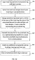
- the mechanical dimensions of the user's intact leg are first measured. The measurement of the intact leg is preferable done with an optical measuring device but any other measuring device can be used. The measuring device can be used to obtain the lengths and relative positions of the intact leg including: the foot, ankle, lower leg, knee and upper leg.
- the lower leg may be coupled to the foot with a movable ankle that includes a ball joint.
- the lower leg has two members that extend from the knee to the ankle.
- the front member can be the primary load bearing structure that is coupled to the ball and socket ankle joint that is built into the foot.
- the rear member can be a flexible structure that is coupled to the front member at the top of the lower leg and the heel of the foot. When the user walks, the front member is rigid while the rear member expands and contracts as the user walks. When the heel contacts the ground, the foot rotates forward and the rear member is compressed. The front member rotates forward and the rear member extends to its normal state when the lower leg is upright and then the rear member is stretched as the lower leg rotates further forward. The elasticity of the rear member provides a spring mechanism for the foot and also allows the foot to rotate side to side.
- the socket shape In addition to the basic leg dimensions, the socket shape must correspond very closely to the end of the amputated limb in order for the prosthetic leg to be comfortable when worn.
- the socket design data is typically provided by a prosthetist. Like the leg surface data, the socket design data can be obtained through optical scanning of the end of the amputated limb. Alternatively, the end of the amputated limb can be measured manually with various mechanical measuring devices. These measurements are used to create a socket surface shape that is substantially the reversed shape of the end of the amputated limb.
- the socket design may also factor in padding materials that are placed between the amputated limb and the socket wall. In an embodiment, the measurements for the end of the amputated limb may also be digitized and stored in electronic memory, so both the socket and leg data can then be combined and used by the CAD system to produce an accurate prosthetic limb for the user.
- the knee design is a stock data file that is selected by the designer based upon the other design parameters of the prosthetic leg. Factors can include side of leg, weight of patient, movement of intact knee, etc. A suitable knee design can be selected based upon this information.
- the knee will include multiple linkages that are coupled to the upper and lower leg.
- the linkages may be elongated members that are coupled to the knee by rods that rotate within holes at the ends of the linkages.
- the multiple linkages allow the prosthetic leg to move in a manner that replicates the movement of an intact knee.
- the knee can also have a locking mechanism that stabilizes the leg.
- the knee may lock in a specific position with a locking mechanism or an automatic locking mechanism that is actuated when the leg is straightened.
- the locking mechanism may have a manual release that is controlled by the user or an automatic release that senses when the user moves the leg forward. eated with a larger radius and two other 90 degree sections may be created wit the user applies weight to the lower leg having a front member and a rear member.
- the front member can be coupled to the ball and socket ankle joint that is built into the foot and the rear member can be a flexible structure that is coupled to the heal of the foot.
- a large diameter rod is coupled to the bottom of the upper leg and extends across the width of the knee and a "C" clamp is placed around the rod and coupled to the lower leg.
- One end of the C clamp is coupled to the top of the front member and a second end of the C clamp is coupled to the top of the rear member.
- the C clamp When the rear member is compressed the C clamp is tightened around the rod locking the lower leg in place.
- the rear member When the user moves forward, the rear member is stretched and the C clamp is loosened which allows the lower leg to rotate relative to the upper leg.
- the C clamp may apply a slight friction against the rod which allows the lower leg to be positioned by the user but prevents the lower leg from swinging freely.
- the knee and ankle of the prosthetic leg may have sliding connections at the knee and ankle.
- lubricants can be used at these connection points.
- lower friction bearings or bushings can be used at these rotating connections.
- the bearings such as ball or roller can be placed in small indentations or recesses in the knee or ankle that function as races or sliding surfaces for the bearings. By inserting the bearings, the rotational friction due to the sliding components is reduced.
- the user's intact foot is scanned and used in the design of the prosthetic leg.
- the intact foot is measured but not scanned.
- a stock foot design that may have a matching length and width is retrieved from a database. The retrieved design data is then integrated into the prosthetic leg design and fabricated simultaneously with the rest of the leg.
- the feet are stock items that are manufactured in various sizes and models. Some feet have energy storing members that allow the user to run more efficiently. Alternatively, the feet can be sized to match the intact foot which would allow a user to wear matching shoes. Digital representations of the stock feet components can be stored in a database that is accessible to the design system.
- the prosthetist uses the CAD based application to combine the leg data with socket, knee and foot data to create a complete virtual prosthetic leg that is displayed on the computer.
- These GUI controls can allow the prosthetic designer to alter the prosthetic design in various ways to customize various attributes of the design within parameters designated by variables built that will control the leg's movement and the appearance.
- a GUI tool can be used, for example, to change the foot, knee and socket components used with the leg.
- the prosthetic designer can create a prosthetic leg that substantially matches the mechanical geometry of the intact leg.
- the prosthetic leg In addition to being the proper dimensions, the prosthetic leg must also be strong enough for the required use. A prosthetic leg must be able to support the user's weight and impact while running or jumping and a prosthetic arm must be able to withstand the normal use forces.
- the strength of the prosthetic limb is determined by the geometry of the prosthetic limb components and the materials used to fabricate the components. Suitable materials include high strength plastics such as high strength polyamide metals, alloys and composites such as carbon fiber in an epoxy binder.
- the CAD system can be used to design the load bearing member of the prosthetic leg.
- the prosthetic leg will be much stronger than required by the user.
- the prosthetic designer can input the weight and activity level of the user into the CAD system and the required strength can then calculate based upon expected loads.
- the CAD system can then design a load bearing structure that will be able to support the load requirements.
- the load bearing member is a simple solid or hollow elongated structure that supports the entire load.
- the prosthetic leg can be an elongated hollow structure that provides an external surface that corresponds to the intact leg.
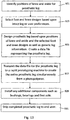
- the design data produced by the CAD system can be used to fabricate the prosthetic leg. Because the information for the socket and leg are in a digital format, the patient can be in a remote location and the leg design information can easily be transmitted electronically to a prosthetic fabricator located in a more industrial area. The leg can then be fabricated using the design data and shipped to the patient located in the remote rural location.
- the prosthetic leg is fabricated through a rapid prototyping process that uses an energy beam directed at a bath of liquid or powdered material. Similar fabrication processes are known as additive manufacturing, rapid manufacturing, layered manufacturing, 3D printing, laser sintering, and electron beam melting (EBM). These fabrication processes use an energy beam that is deflected across the material and causes the exposed material to harden. Another possible manufacturing process is fused material deposition (FDM).
- FDM fused material deposition
- the cross section design data is used by the fabrication machine to construct the main or entire leg assembly in a sequential series of layers. As each layer of material is hardened, the completed portion of the leg component is moved vertically into the bath and the next cross section layer is formed and fused to the adjacent formed layer. When all layers are formed, the leg component is completed. Because the fabrication process can be precisely controlled to create sliding surfaces, even the knee can be fabricated simultaneously with the other portions of the prosthetic leg.
- the prosthetic leg is fabricated as a single integrated structure with the upper leg, knee, lower leg and foot all being fabricated simultaneously so that the finished product is complete.
- the moving components of the inventive prosthetic leg are coupled to the knee having rotating components.
- the knee may have linkages or rotating components that have rods that rotate within holes.
- the rapid prototyping method can simultaneously produce the rods and corresponding holes most accurately when the holes and rods are formed by depositing layers of material that are perpendicular to the center axis. Thus, the layers are sequentially formed and perpendicular to the center axis of the holes and rods.
- the knee rotates about an axis that is substantially perpendicular to the length of the leg and parallel to the ground, thus the holes and rods will be aligned across the width of the knee. Since the entire leg is fabricated simultaneously, the layers that form the leg will be sequentially formed from one side of the leg to the opposite side.
- the leg may have one or more replaceable stock components that can be added or replaced after fabrication.
- the foot may be a stock component that is attached to the lower leg.
- the socket may be removable or adjustable so that the socket can be modified as the end of the user's amputated limb changes.
- the present invention is a custom designed prosthetic limb having an integrated construction.
- the inventive prosthetic limb is primarily directed towards prosthetic legs but the same design and fabrication processes can also be used to create prosthetic arms.
- the prosthetic limb is preferably designed by an industrial designer using a Computer Aided Design (CAD) program.
- CAD Computer Aided Design
- the inventive prosthetic leg includes a load bearing component that functions as the human femur, knee, tibia and foot.
- the upper leg of the load bearing component is attached to a socket that engages the end of the amputated limb.
- the lower end of the upper leg and the upper end of the lower leg are coupled to the artificial knee.
- the lower end of the lower leg is coupled to an artificial foot.
- the mechanical data for the prosthetic leg may include the relative positions of the socket, knee and foot as well as the movement of these components based upon geometry and movement of the intact leg.
- the mechanical data for a patient can be provided by a prosthetist. This mechanical data is digitized and input into a CAD program that is referenced to design the prosthetic leg.
- An example of a suitable CAD program is Pro/Engineer by Parametric Technology Corporation.
- Other CAD software includes: SolidWorks by SolidWorks Corporation a subsidiary of Dassault Systèmes, S. A.
- the exterior surface of the prosthetic leg is a mirror image that is matched to the user's intact leg.
- the surface data of the intact leg can be obtained through a laser scanning process and input into the CAD program.
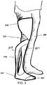
- the intact leg 205 is scanned with a three-dimensional laser scanner 207.
- the leg 205 must be scanned from multiple sides to obtain a full three dimensional digital image.
- the scanner 207 creates a data set of geometric measurements for many points on the surface of the leg 205. The accuracy and detail of the three dimensional digital image is improved by taking more measurements of the leg 205.
- the described laser scanning method can also be used to obtain the surface measurement data for the end of the amputated limb 209.
- Photo detectors may be used to collect color information so that the exact color(s) of the intact leg 205 can be determined and used to create the prosthetic leg 211.
- Suitable handheld laser scanners include the FastSCAN system by Polhemus and the Handyscan 3D system by Handyscan. While optical scanning is the preferred method for determining the surface of the intact leg, in other embodiments any other optical, electromagnetic or mechanical method can be used to obtain this surface information.
- While some scanning systems are capable of detecting a surface contour with a resolution less than a millimeter, the described scan does not require this level of accuracy to create a prosthetic leg that appears substantially like the outer surfaces of the intact leg.
- scanning mechanisms such as bar code readers to scan the user's intact leg. Grocery store bar code readers that have been discarded and modified have been used to produce acceptable surface data that can be used to create the outer surfaces of the prosthetic leg.
- the scan data is converted into a usable surface file that can be read by the CAD program. More specifically, the surface data from scan of the intact leg 205 may be referenced in order to extrapolate the shape of the intact leg 205 through a reconstruction process.
- the reconstruction process uses an algorithm that connects the adjacent points, known as a point cloud, with lines from the scanned leg data to construct a continuous surface from many small polygon shapes that form a polygon model.
- the data produced by the reconstruction process is a continuous three dimensional digital representation that closely matches the surface of the intact leg 205.
- the same reconstruction process can be used to obtain the surface data for the end of the amputated limb 209.
- An example of the software used to perform the scanner data reconstruction process is Geomagic Studio by GeoMagic and Pro Scan Tools which is a plug in module for Pro/Engineer by Parametric Technology Corporation.
- the reconstruction surface file for the intact leg is input into the CAD program.
- the prosthetic designer can use the CAD program to reverse mirror and manipulate the intact leg data to create a mirror image digital representation.
- This mirror image data can then be used in the design of the exterior surface of the prosthetic leg.
- the leg and socket data are used to form the outer surfaces of the prosthetic leg.
- the sound side leg geometry is referenced in the creation of the exterior prosthetic surfaces, while the data representing the end of the amputated limb is referenced to create the socket for the upper leg.
- moving components are also required for a fully functional prosthetic leg including an artificial knee and ankle.
- the user can consult with a prosthetist to determine the exact relative placement of the artificial knee 331 and foot 335 in relation to the end of the amputated limb 209.
- the prosthetist can use the measurement of the intact leg 205 and use this information as a starting point to determine the relative positions of the socket, artificial knee 331 and foot 335 in the prosthetic leg.
- the placement of the artificial knee 331 and foot 341 relative to the end of the amputated limb 209 are specified by the prosthetist and input into the CAD program. These components can be displayed within the prosthetic leg on a computer.
- the CAD program can manipulate the components to enlarge, rotate, add or remove or change components and show the movement of the prosthetic leg. All internal mechanical design information can be saved in computer readable format for future modification or prosthetic fabrication. This can be particularly useful when the patient is a child who is still growing.
- the prosthetic data can be altered to account for the growth. Revising a stored prosthetic leg design can be easier than generating an entirely new leg.
- the prosthetic leg can include inner and/or outer structural components that are used to construct the upper and lower legs.
- the upper and lower legs can be elongated load bearing members may have an outer surface that is load bearing and internal structures that are also load bearing.
- the internal structure can be an elongated solid member and the outer structure can be an elongated hollow member that is a mirror image of the intact leg.
- the inner and outer structures can be coupled with additional members and that form a framework or lattice.
- the outer surfaces of the leg can have sufficient strength to support the required loads without any internal load bearing structures.
- the outer surface may match or resemble the intact leg while the internal volume of the leg is an open space. The hollow spaces allow the prosthetic leg to be light weight and strong enough to support the user's weight.
- the lower leg 323 can also include two elongated members, a front member 337 that provides most of the strength required to support the weight of the user and a rear member 335.
- the compressive force can be distributed between the front member 337 and rear members 335.
- the front member 337 and rear member 335 can perform functions other than providing compressive strength.
- the prosthetic designer can provide a flexible connection between the foot 341 and lower leg 323 so the foot 341 may rotate at the ankle area.
- the rear member 335 may be flexibly coupled to the back of the foot 341 so that the foot 341 can move in a more natural and comfortable manner.
- the foot 341 may also be designed to be more flexible so that it provides some cushioning while the user is walking. Since the entire leg 205 is preferably made of the same plastic material, flexibility can be designed into specific areas of the foot 341 by using thinner material cross sections that are parallel to the axis of rotation so the front of the foot 341 can bend relative to the rear foot 341. Since the plastic materials used to create the leg 205 are elastic, the bending of the foot 341 can be proportion to the forces applied to the foot 341. For example, a greater force will be applied to the foot 341 when the user is running than when walking resulting in increased bending of the flexible components.
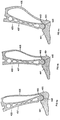
- Figs. 4a, 4b and 4c are cross sectional views of an alternative embodiment of the lower leg 423 and foot 441.
- the upper ends of the front member 437 and the rear member 435 are coupled below the knee of the lower leg 423.
- the front member 437 extends in a substantially straight path to the foot 441 and functions as the primary load bearing structure.
- the bottom of the front member 437 may have a cylindrical, ball or convex spherical surface 443 which slides within a corresponding, cylindrical or spherical socket 445 in the foot 441.
- the socket 445 surrounds the upper portion of the ball surface 443 so the ball surface 443 is captured within the concave spherical socket 445 and the foot 441 is securely coupled to the lower end of the front member 437.
- the rear member 435 extends from the connection with the front member 437 at the top of the lower leg 423 in a curved shape to the heel of the foot 441.
- the rear member 435 holds the foot 441 in place and provides a spring mechanism that allows the foot 441 to rotate relative to the lower leg 423. Because the rear member 435 is curved, the distance between the ends of the rear member 435 can be stretched or compressed elastically as the foot 441 moves relative to the front member 437.
- the rear member 435 is preferably much thinner than the front member 437 so that it is able to flex and control the foot 441 resistance to rotation relative to the lower leg 423.
- the prosthetic designer can alter the rear member 435 to provide a specific spring rate. A heavier user will require a stiffer spring rate than a lighter weight user. Similarly, a less active user may prefer a lower spring rate than an athletic user.
- Fig. 4a illustrates the leg in a heel 451 forward portion with the foot 441 angled forward relative to the front member 337.
- the movement of the foot 441 causes the rear member 435 to be compressed which results in a larger outward bowing.
- Fig. 4b shows the leg in the normal straight position.
- the foot 441 is substantially perpendicular to the lower leg 423 and the rear member 435 is in its natural state.
- Fig. 4c illustrates the leg in a forward position relative to the foot 441.
- the ball surface 443 has rotated within the socket 445 and the rear member 435 has been stretched which causes the curvature of the rear member 435 to flatten. Since the rear member 435 is flexed elastically, when forces are not applied to the foot 441, the foot 441 will tend to return to a normal position perpendicular to the front member 437 of the leg.
- the bottom of the front member 437 is a ball surface 443 which can rotate in any direction including side to side.
- the foot 441 can rotate so that the bottom of the foot 441 will adjust to the uneven surface.
- the rear member 435 will also bend elastically to the side.
- the side to side spring rate of the rear member 435 can be different than the front to back movement. Since the side to side movement will cause the rear member 435 to deflect sideways, the side to side spring rate is controlled by the thickness of the rear member 435.
- a thicker rear member 435 will be more resistant to side to side movement than a thinner rear member 435.
- the thickness of the rear member 435 is preferably designed to provide side to side stability but also provide some rotational movement to allow the foot 441 to have the maximum contact area with the surface so that traction is improved and the foot 441 is less likely to slip and cause the user to fall.
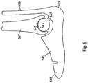
- the foot 541 may incorporate a ball surface 543 that is mounted to the end of a flexible post 557 which can provide additional cushioning for the user.
- the foot 541 impacts against a surface, the user's body weight is applied against the leg and compresses concave spherical surface 545 of the front member 537 against the ball surface 543. Since the post 557 is not directly under the ball surface 443 and the front member 537, the impact causes the post 557 to elastically flex downward.
- This deflection is elastic flexing of the post 557 which cushions the impact force of the user's weight.
- the ball surface 543 may slide against a spherical socket 545 at the bottom of the front member 537.
- the rear member 535 is flexible but rigidly coupled to the back of the foot 541 which allows the foot 541 to move in the same manner illustrated in Figs. 4a and 4b as well as side to side.
- the prosthetic designer can control the spring rate of the lower leg based upon the spring rate of the post 557.
- a thicker post 557 can be used with heavier and more athletic users.
- the artificial foot used with the prosthetic leg can also be selected from a database of feet. Like the artificial knees, digital representations of the various different sizes and shapes of feet may be available. The proper foot may also be selected for the patient by the prosthetist and the digital representation can be used in the design of the prosthetic leg.
- the foot may be designed to be flexible so that it provides energy storage and cushioning when compression forces are applied to the heel and toe.
- the entire leg can be fabricated simultaneously so that the knee and foot are integrated and inseparable from the prosthetic leg. The simultaneous fabrication also allows the knee and foot to have a mechanical relationship, so that knee motion is directly influenced by foot angle. This mechanical relationship does not occur when knee and foot are fabricated independently, usually by separate manufacturers.
- the toe portion 545 of the foot 541 can also move relative to the heel portion of the foot 541.
- the plastic materials used to create the prosthetic leg can be elastic and the components can be made rigid or flexible based upon their thickness at the area of bending.
- the foot 541 can have a thin flexible section which allows the foot 541 to bend at an area where the toes 545 would normally bend.
- the toes are normally aligned with the rest of the foot 547.
- the area 545 may flex so that the front of the foot 541 remains in full contact with the surface.
- the front of the foot 541 is separated from the surface, it will return to a normal aligned position relative to the foot 541. This feature allows the prosthetic foot 547 and leg to move in a more natural manner.
- the bottom of the foot contacts the ground and provides gripping force that stabilizes the leg and makes walking with the prosthetic leg possible.
- the user can place a shoe over the foot to provide the required traction with the ground.
- the main foot may be made of a hard polyamide while the bottom of the foot may be an elastic rubber type material that is attached to the main foot.
- the elastic material provides traction and cushioning so the user does not have to wear a shoe over the foot.
- the thickness of the foot may be configured to match the user's intact foot without shoes.
- the bottom of the foot includes grip areas that provide traction and resist slipping.
- an elastic layer may also be releasably attached to the bottom of the foot so that when the user is wearing a shoe on the intact foot, the layer can be attached to the foot so the length of the prosthetic leg matches the length of the intact leg and the shoe.
- the elastic material can be one or more pieces that can be textured to provide additional traction particularly on wet surfaces.
- the elastic material can be attached to the foot by elastically surrounding a portion of the foot or alternatively attached by fasteners such as straps, screws, Velcro, etc. This configuration gives the user the option of wearing a shoe on the prosthetic foot or attaching a layer to the prosthetic foot to provide matching leg lengths.
- the knee which can be a simple hinge type coupling or in other embodiments, the prosthetic knee may have a plurality of movable linkages which mimic the complex movement of a human knee.
- the multi-linkage knee is designed to cause the lower prosthetic leg to move in a manner that matches the movement of the intact leg. Because the knee is a movable structure with rods that rotate within holes or bushings, the tolerances between the moving components must be very close to avoid having an unstable knee.
- the knee must also provide a substantial amount of strength to support the applied forces.
- the linkages used in the knee are preferably solid structures that pivot at each end. The strengths of the linkages can be improved by increasing their thickness or configuring the knee with multiple linkages can be arranged in parallel across the width of the knee.
- the knee can be a stock design that includes a multiple linkage assembly that mimics the movement of a human knee. Different knee designs may be used for different sized patients and different types of expected use. The prosthetic designer can select an appropriate knee design based upon the user's physical characteristics including: size, weight, activity level, mobility, strength, intact knee movement, etc. The dimensions and movements of the different knee designs can be stored in a computer database.
- the knee designs may include a plurality of linkages that are coupled to the upper and lower leg. The knee linkages are preferably connected by rods and holes may rotate to simulate the movement of a human knee. Because the linkage rotation results in sliding friction between the components, the sliding surfaces may require lubrication.
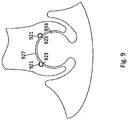
- Fig. 6a and 6b are cross sectional views of a multi-link embodiment of a knee 651 portion of the prosthetic leg 623 in different positions.
- the upper leg is aligned with the lower leg and the knee 651 is in the straight position.
- Fig. 6b illustrates the knee 651 in a partially bent position.
- the circular features 653 represent rods which have circular cross sections and rotate within cylindrical holes. The rotation of the knee 651 allows the leg to rotate.
- the lower leg may be locked in place so that a user can apply weight to the leg without having it bend and collapse.
- the locking mechanism can be a mechanical device such as a locking device such as a screw or a lever.
- the locking mechanism can be a device that responds to the user's movement.
- the knee 651 may lock when the foot is on the ground and the leg is straightened. The knee 651 may unlock when the user lifts the foot and moves the knee forward to initiate a forward walking motion.
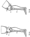
- Fig. 7a illustrates another embodiment of the inventive prosthetic leg 951 which has an automatic knee locking mechanism.
- a large diameter rod 961 is coupled to the bottom of the upper leg 953 and extends across the width of the knee.
- a "C" clamp 971 is coupled to the lower leg 955 with one end coupled to the front member 957 and the opposite end coupled to the rear member 935.
- the lower leg 955 With reference to Fig. 7a , the lower leg 955 is shown in the upright position.
- a normal amount of compressive force may be applied to the rear member 935 which causes the C clamp 971 to tighten around the rod 961.
- the lower leg 955 is held in place when the user is standing upright and can be positioned by the user.
- Figs. 7b, 7c and 7d show the lower leg 955 when the user is walking.
- the rear member 935 is compressed as the foot rotates forward as shown in Fig. 7b , the C clamp 971 is tightened around the rod 961 which locks the lower leg 955 in place and provides support for the user as weight is transferred to the lower leg 955.
- the ends of the C clamp 971 are much closer together.
- Fig. 7c as the user moves forward, the lower leg 955 rotates over the foot 947 and the heal lifts from the ground. When the lower leg 955 is rotated forward, the rear member 935 is stretched.
- the ends of the C clamp 971 are spread apart and the C clamp 971 is loosened which allows the lower leg 955 to rotate around the rod 961.
- the rear member 935 is not under compression and does not lock the C clamp 971 in position around the rod 961.
- the lower leg 955 may rotate or may be movable by the user to position the lower leg 955 if necessary.
- the lower leg 955 is lifted and rotated back to mimic the movement of a human leg. As the leg rotates forward, the lower leg 955 will rotate forward to the straight position shown in Fig. 7b and the described step process is repeated.
- the upper leg is coupled to the cylindrical rod 961 which is surrounded by the C clamp 971.
- the C clamp 971 has a first end 981 coupled to an outer structure that extends around the top and front of the knee and is attached to the front member 957 of the lower leg.
- the second end 983 of the C clamp 971 is coupled to the rear member 935 of the lower leg 955.
- the configuration of the C clamp 971 also provides some cushioning when the user walks.
- the C clamp 971 may only be coupled to the lower leg by the first end and the second end. Thus, the C clamp 971 can flex as the weight of the user is applied to the cylindrical rod 961 from the upper leg 953.
- the "C” clamp is illustrated as a flexible structure made from a plastic material, it is also possible to use a strap brake which is a thinner material that replaces the C clamp but functions in the same way.
- the strap brake is tightened around the cylindrical rod when the heal contacts the ground and the rear member is compressed. When the user moves forward over the front of the foot the heel is lifted and the rear member is in tension which releases the tension of the strap brake around the cylindrical rod which allows the lower leg to rotate.
- the entire prosthetic leg may be made of a single material, some portions of the material areas will slide against the same material. Because the materials have the same hardness, both pieces will tend to wear. Without a self lubricating material, the sliding can result in wear and damage to the sliding surfaces within the foot and knee. This can result in friction as the smooth sliding surfaces are damaged which will alter the movement of the knee and foot and may eventually cause the leg to fail.
- the material used to fabricate the prosthetic leg is a self lubricating plastic material that can slide against itself without damage. It is also possible to place a lubricating material such as grease, graphite or Teflon at the sliding areas to reduce the sliding friction. A lubricant can also be used between the components to reduce sliding friction and reduce erosion of the surfaces. In an embodiment, the sliding surfaces may have recesses or porous areas that are impregnated with a lubricating material. The lubricant can be replaced as it is consumed.
- additional components can be added to the prosthetic leg so that the components do not slide against the same material.
- bushings or bearings can be added to the leg at the points of rotation.
- the bushings may be made of lubricious materials such as, stainless steel, ceramic, Delrin or Teflon.
- bearings are used.
- the bearings may be sealed units with roller, needle, ball bearings or any other type of bearing.
- the bearing material may be ceramic, metal or plastic. Known mechanisms may be used to retain the bushings and/or bearings between the sliding surfaces.
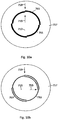
- the sliding concave (or convex) surfaces can have recessed areas 921 that provide voids, holes or indentations that retain the bearings 923 in the desired positions.
- the bearings 923 can be balls, cylindrical rollers or any other type of rotating bearing structures or sliding bushing structures. These recessed areas 921 can function as bearing races that keep the bearings 923 or bushings evenly distributed around the sliding surfaces.
- the bearings 923 are spherical and the recessed areas 921 are circular, cylindrical or semi-spherical in shape and formed in the concave surface 927. The bearings 923 rotate against the outer convex spherical surface 933 of the ankle that is coupled to the foot (not shown).
- the described bearing system may also improve the manufacturability of the inventive prosthetic leg.
- the components are fabricated simultaneously using a rapid prototyping machine. While the parts can easily be fabricated simultaneously, it can be difficult to create parts such as ball and sockets that are smooth and have a very tight spacing.
- the spacing is much less critical.
- the sliding components can be fabricated simultaneously with a larger gap between the moving components. After fabrication, the bearings can be inserted between the components. The bearings provide a smooth sliding mechanism and also tighten the fit between the sliding components. If the bushings or bearings wear out, they can be replaced so the leg can be repaired. In contrast, it can be much more difficult to repair a sliding fit connection if the sliding surfaces have been eroded away.
- the CAD system can include a graphical user interface (GUI) that allows the prosthetic designer to easily change the appearance of the leg and fairing.
- GUI graphical user interface
- the GUI may be a special, custom, proprietary application, or it may simply be a CAD model that is built inside Pro/E.
- the GUI can have controls that allow the prosthetic leg to be viewed with a specific color that preferably matches the user's skin color but may also be any other color.
- the design data produced by the CAD software can, when coupled with the unique data of the mirrored scan data taken from the sound side leg, be used to create a unique and custom fabricated leg.
- Rapid prototyping is a general category of systems that uses digital design data and software to fabricate the components from various types of materials including metals and plastics. These machines most often use an energy beam that is deflected across a bed of liquid or powdered material. The exposure to the energy beam causes the material to fuse together and harden. These fabrication machines are able to create all custom prosthetic limb components.
- the CAD design data In order to fabricate the prosthetic leg components with the rapid prototyping machines, the CAD design data must be modified.
- the normal CAD design data for a component is converted into many parallel cross sections of vector data that extend along the length of the component.
- the data transmitted between the CAD software and the fabrication machine approximates the shape of the component cross sections through many connected triangular facets. Smaller facets produce a higher quality surface but require more time to calculate and can create very large manufacturing data sets.
- the output of the CAD design program can be a standard STL file that is an export option, similar to a JPG export or any other file format.
- the vector data for the component cross sections is read by a rapid prototyping scanner controller that converts the vector data to movement information which is sent to the energy beam scanhead.
- the rapid prototyping machine includes a scanhead having two mirrors that deflect the laser beam in the X and Y coordinates over a bath of liquid or powder material.
- the fabrication information is then used to control the print head cross section to create each component cross section successively.
- the scanhead controller reads the fabrication data and causes the print head to expose successive layers of liquid, powder, or sheet material to precise patterns of laser light. Once the layer is completely formed, the component is moved into the bath so a thin layer of the material covers the previously formed layer. The process is repeated many times with new layers formed and fused to the previously formed layers.
- an electron beam is deflected over a bath of material in the X and Y coordinates with magnetic fields.
- the component cross sections are sequentially formed until the component fabrication is completed.
- the primary advantage to additive fabrication rapid prototyping is the ability to create very complex shapes and geometric features such as the internal framework and exterior surfaces of the prosthetic leg.
- a light weight and strong prosthetic limb can be made with a rapid prototyping machine from plastic materials such as photopolymers.
- An additional benefit of rapid prototyping is the ability to create complex, interlinked and assembled parts in one run.
- traditional means used by the prior art required the individual manufacture many parts, followed by an assembly of the parts. Thus, the assembly can add significant costs, even though the individual parts may themselves cost very little to produce.
- the rapid prototyping process can be applied to various materials including thermoplastics, photopolymers, metal powders, eutectic metals, titanium alloys and other materials. Because the inventive prosthetic leg is intended to be inexpensive, the preferred material is a thermoplastic material. Examples of some suitable rapid prototyping machines include: laser sintering machines by EOS GmbH, electron beam sintering machines by Arcam AB and laser stereo lithography machines and selective laser sintering machines by 3D Systems Corp. Similar fabrication processes are known by the names: additive manufacturing, rapid manufacturing, layered manufacturing, 3D printing, laser sintering, electron beam melting (EBM), etc. All of these fabrication processes use a similar operating principle of scanning an energized beam over a bath of material to solidify a precise pattern of the material to form each layer until the entire component is complete.
- EBM electron beam melting
- FDM fused material deposition
- the knee 651 may include a plurality of rotatable linkages that are coupled to rods 653 that rotate within holes.
- Current rapid prototyping machines are capable of forming assemblies with rods within holes simultaneously. However a small gap between adjacent components is required to prevent the rod from being fused to the hole during the fabrication process. In order to provide a sufficient gap as well as a tight tolerance, the rod and corresponding hole may not be perfectly circular in cross section.
- a cross sectional view of a rod 753 and a hole 755 in a linkage component 757 are shown.
- the rod 753 has two opposite 90 degree section may be created with a larger radius and two other 90 degree sections may be created with a smaller radius. The difference between the larger radius and the smaller radius may be the gap 761 required by the rapid prototyping fabrication process.
- the rod 753 has a loose fit within the hole 755 due to the gap 755.
- the original orientation of the rod 753 and the hole 755 are indicated by the arrows 759 on the upper side which are aligned.
- the rod 753 may be rotated within the hole 755 so that the arrows 759 are offset by 90 degrees.
- the larger radius section of the rod 753 is adjacent to the smaller radius of the hole 755 with a tight gap that still allows free sliding rotation. This creates two sliding surfaces between the rod 753 and hole 755 that are very closely fit and two other adjacent surfaces that are separated by a much larger gap 761. As discussed above, this method for forming tight tolerance sliding surfaces may not be required if bearings are inserted into indentations in the sliding surfaces.
- FIG. 11 With reference to Fig. 11 , the fabrication of a rod 753 and hole 755 using a rapid prototyping machine is illustrated. The fabrication is most precisely controlled when the rod 853 and hole 855 are substantially perpendicular to the sequential planes of deposited material. The described rod 753 and hole 755 configuration allows the rapid prototyping machine to be used to create a knee having rotating components with tight tolerances.
- the prosthetic leg may be formed with the knee in a bent position.
- An angle of 180 degrees represents a straight leg.
- the upper leg and the lower leg may be bent at an angle of about 270-350 degrees with the rods and holes of the linkages fabricated with the required gap in the manner described above.
- the knee can be rotated to the normal functional range of about 180 to 260 degrees.
- the rods and holes of the knee linkages may have close tolerance fits resulting in a smooth rotating prosthetic knee.
- a mechanism may prevent the leg from rotating beyond the 260 degree bend where the rods and holes of the knee linkages will have a large gap. This close fitting embodiment may be required when other types of bearings or bushings are not used to keep the components in a tight rotational configuration.
- a prosthetic designer scans the patient's intact leg and end of the amputated leg with a laser scanner 901.
- Mirror image data is created from the scan of the intact leg and reversed surface is created from the scan of the end of the amputated limb.
- the foot and a knee are integrated into the prosthetic leg based upon a pre-designed program 903.
- the prosthetic leg is then designed using the mirror image data to create an exterior surface, the reversed surface to create a socket.
- the locations of the knee and foot are identified and the knee and foot are incorporated into the leg design in positions that match the intact leg.
- a prosthetic leg design is then converted into an electronic data file 905.
- the prosthetic leg data file is transmitted to a rapid prototyping machine which creates the leg in a single fabrication process from a photopolymer material 907. Any additional components are required such as bushings, bearings or foot sole inserts, these components can be installed at the fabricators facilities 909.
- the completed prosthetic leg is then shipped to the end user 911. This process allows amputees located in very remote areas to obtain prosthetic limbs. Since digital data can be transmitted on digital media via mail, electronically via cell or satellite, the inventive process greatly improves the design, fabrication and distribution of prosthetic legs.
- a generic leg that is designed to resemble an intact leg without scanning the outer surface of the intact leg.
- the sequential process by which the inventive prosthetic leg can be fabricated without the scanned data is represented by Fig. 13 .
- a prosthetic designer determines the positions of the knee and ankle for the prosthetic leg 921.
- the surface data for the prosthetic leg is obtained from a generic leg.
- the foot and a knee are integrated into the prosthetic leg based upon a pre-designed program 923.
- the prosthetic leg is then designed using the genetic leg to create an exterior surface.
- the exterior surface can be modified to include measurements taken from the intact leg.
- the generic leg can be modified to have the same length and width as the intact leg at corresponding vertical positions.
- the knee and foot are incorporated into the leg design in positions that match the intact leg.
- a prosthetic leg design is then converted into an electronic data file 925.
- the prosthetic leg data file is transmitted to a rapid prototyping machine which creates the leg in a single fabrication process from a photopolymer material 927. Any additional components are required such as bushings, bearings or foot sole inserts, these components can be installed at the fabricators facilities 929.
- the completed prosthetic leg is then shipped to the end user 931.
- inventive system has been described with reference to particular embodiments, however additions, deletions and changes could be made to these embodiments without departing from the scope of the inventive system.
- the same processes described for designing and fabricating a prosthetic leg can also be applied to the design and construction of a prosthetic arm that can include a socket, an elbow, an elongated member and an artificial hand.
- the prosthetic limbs that have been described include various components, it is well understood that these components and the described configuration can be modified and rearranged in various other configurations.
Landscapes
- Health & Medical Sciences (AREA)
- Transplantation (AREA)
- Engineering & Computer Science (AREA)
- Vascular Medicine (AREA)
- Oral & Maxillofacial Surgery (AREA)
- Cardiology (AREA)
- Biomedical Technology (AREA)
- Heart & Thoracic Surgery (AREA)
- Life Sciences & Earth Sciences (AREA)
- Animal Behavior & Ethology (AREA)
- General Health & Medical Sciences (AREA)
- Public Health (AREA)
- Veterinary Medicine (AREA)
- Orthopedic Medicine & Surgery (AREA)
- Manufacturing & Machinery (AREA)
- Prostheses (AREA)
Description
- A prosthesis limb replaces a missing extremity, such as an arm or a leg and may be needed for a variety of reasons, including diseases, and accidents. An artificial limb may also be needed when a person is born with a missing or damaged limb(s). The type of prosthesis limb used is determined largely by the extent of an amputation or loss and location of the missing limb. A transtibial prosthesis is an artificial leg that is attached to a user below the knee and includes a lower leg, ankle and foot. The transfemoral prosthesis is an artificial leg that is attached to the user's amputated limb above the knee and includes an upper leg and mechanical knee. A transradial prosthesis is an artificial arm that is attached to the user below the elbow and includes a forearm and hand. A transhumeral prosthesis is an artificial arm that is attached to the user above the elbow.
- In developing areas of the world, including large portions of Africa, the leading causes of amputations are industrial, vehicular, and war related accidents. In more developed areas, such as North America and Europe, the leading causes for the amputations are diseases including cancer, infection and circulatory. In the United States, approximately 100,000 legs are lost each year to diabetes, vascular disorder, accidents and cancer. Because there are so many amputations, there is a substantial need for prosthetic limbs.
- The engineering of prosthetic limbs has improved greatly. In particular, artificial knees and feet have been developed for prosthetic legs that provide increased mobility and functionality. While the engineering and mechanics of prosthetic limbs have evolved greatly, very little thought has been given to the aesthetics of the human being for whom the device was intended. With reference to
Figure 1 , amodern prosthetic leg 101 is shown having asocket 121 that has a recessed surface that engages the end of the user's amputated leg. Thesocket 121 is typically a padded plastic structure that distributes the compression forces on the end of the amputated limb. The bottom of thesocket 121 is attached to apylon 123 which is a tubular support that can be made of titanium or aluminum. The pylon can be manufactured through an extrusion process. The bottom of thepylon 123 is attached to anartificial foot 125 that can be a molded plastic structure. Theprosthetic leg 101 may also have a foam covering 127 and can be attached to thesocket 121 andpylon 123 to provide a more uniform shape. Thevarious socket 121,pylon 123 andfoot 125 can be coupled together using fasteners including bolts, screws and adhesives. -
US 6 955 692 B2 discloses a leg prosthesis adapted to a thigh stump including an adapter for a knee joint, a knee joint mounted on this adapter, and a prosthetic lower leg coupled to the knee joint. A prosthetic foot is attached to this prosthetic lower leg and can pivot into a toes-raised foot position. A force-transmitting element moves the prosthetic foot substantially from the toes-down foot position to the toes-raised foot position during bending of the knee joint. Each bending position of the knee joint is transformed by a converter into an unambiguous electrical signal which is supplied to a programmable control device which generates a signal used to control an electrically adjustable actuator which increases or decreases the resistance of the knee joint against or for further bending according to the signal. - A problem with the existing prosthetic limbs is that they are not readily available to people who live in remote parts of the world. Many of these people do not have access to prosthetic limb manufacturers. Also, since prosthetic limbs are very expensive, many people do not have the financial resources to purchase them. Without these resources, the amputees cannot obtain properly designed prosthetic limbs and may rely upon other devices for mobility such as crutches or wheelchairs. One shortcoming of a lower-quality leg is a knee that consists of a basic hinge. While this does allow upper and lower leg to rotate similar to a human leg, the knee does not lock out with each stride, increasing the risk of a fall or uncertain step. While these devices provide basic mobility, they are not as practical as prosthetic limbs since they require the use of arms. Thus, the user cannot use his or her arms while moving. What is needed is a more cost effective prosthetic limb that can be built for patients with minimal equipment.
- The present invention is directed towards an improved prosthetic limb that can be fabricated to match the mechanical dimensions of a user's intact limb. The prosthetic limb is created by a prosthetic designer using computer aided design (CAD) software and computer controlled fabrication processes. While the prosthetic limb is described as a leg, the same processes can be used to fabricate prosthetic arms, and as such, prosthetic arms are intended to fall within the scope of the present invention.
- A prosthetic leg is created for a patient using a computer aided design system. The prosthetic leg can include an upper leg, knee, lower leg, and foot. If the user has a sound leg, a prosthetic leg having matching mechanical dimensions can be designed. In order to accurately create a matching prosthetic leg, the mechanical dimensions of the user's intact leg are first measured. The measurement of the intact leg is preferable done with an optical measuring device but any other measuring device can be used. The measuring device can be used to obtain the lengths and relative positions of the intact leg including: the foot, ankle, lower leg, knee and upper leg.
- The lower leg may be coupled to the foot with a movable ankle that includes a ball joint. In an embodiment the lower leg has two members that extend from the knee to the ankle. The front member can be the primary load bearing structure that is coupled to the ball and socket ankle joint that is built into the foot. The rear member can be a flexible structure that is coupled to the front member at the top of the lower leg and the heel of the foot. When the user walks, the front member is rigid while the rear member expands and contracts as the user walks. When the heel contacts the ground, the foot rotates forward and the rear member is compressed. The front member rotates forward and the rear member extends to its normal state when the lower leg is upright and then the rear member is stretched as the lower leg rotates further forward. The elasticity of the rear member provides a spring mechanism for the foot and also allows the foot to rotate side to side.
- In addition to the basic leg dimensions, the socket shape must correspond very closely to the end of the amputated limb in order for the prosthetic leg to be comfortable when worn. The socket design data is typically provided by a prosthetist. Like the leg surface data, the socket design data can be obtained through optical scanning of the end of the amputated limb. Alternatively, the end of the amputated limb can be measured manually with various mechanical measuring devices. These measurements are used to create a socket surface shape that is substantially the reversed shape of the end of the amputated limb. The socket design may also factor in padding materials that are placed between the amputated limb and the socket wall. In an embodiment, the measurements for the end of the amputated limb may also be digitized and stored in electronic memory, so both the socket and leg data can then be combined and used by the CAD system to produce an accurate prosthetic limb for the user.
- The knee design is a stock data file that is selected by the designer based upon the other design parameters of the prosthetic leg. Factors can include side of leg, weight of patient, movement of intact knee, etc. A suitable knee design can be selected based upon this information. In a preferred embodiment, the knee will include multiple linkages that are coupled to the upper and lower leg. The linkages may be elongated members that are coupled to the knee by rods that rotate within holes at the ends of the linkages. The multiple linkages allow the prosthetic leg to move in a manner that replicates the movement of an intact knee. In addition to providing realistic movement, the knee can also have a locking mechanism that stabilizes the leg. For example, the knee may lock in a specific position with a locking mechanism or an automatic locking mechanism that is actuated when the leg is straightened. The locking mechanism may have a manual release that is controlled by the user or an automatic release that senses when the user moves the leg forward.
eated with a larger radius and two other 90 degree sections may be created wit the user applies weight to the lower leg having a front member and a rear member. The front member can be coupled to the ball and socket ankle joint that is built into the foot and the rear member can be a flexible structure that is coupled to the heal of the foot. A large diameter rod is coupled to the bottom of the upper leg and extends across the width of the knee and a "C" clamp is placed around the rod and coupled to the lower leg. One end of the C clamp is coupled to the top of the front member and a second end of the C clamp is coupled to the top of the rear member. When the rear member is compressed the C clamp is tightened around the rod locking the lower leg in place. When the user moves forward, the rear member is stretched and the C clamp is loosened which allows the lower leg to rotate relative to the upper leg. When the lower leg is lifted and the rear member is in a normal state, the C clamp may apply a slight friction against the rod which allows the lower leg to be positioned by the user but prevents the lower leg from swinging freely. - The knee and ankle of the prosthetic leg may have sliding connections at the knee and ankle. In order to minimize the friction, lubricants can be used at these connection points. Alternatively, lower friction bearings or bushings can be used at these rotating connections. In an embodiment, the bearings such as ball or roller can be placed in small indentations or recesses in the knee or ankle that function as races or sliding surfaces for the bearings. By inserting the bearings, the rotational friction due to the sliding components is reduced.
- In an embodiment, the user's intact foot is scanned and used in the design of the prosthetic leg. In another embodiment, the intact foot is measured but not scanned. Rather than fabricating a mirror image foot, a stock foot design that may have a matching length and width is retrieved from a database. The retrieved design data is then integrated into the prosthetic leg design and fabricated simultaneously with the rest of the leg. In yet another alternative embodiment, the feet are stock items that are manufactured in various sizes and models. Some feet have energy storing members that allow the user to run more efficiently. Alternatively, the feet can be sized to match the intact foot which would allow a user to wear matching shoes. Digital representations of the stock feet components can be stored in a database that is accessible to the design system.
- The prosthetist uses the CAD based application to combine the leg data with socket, knee and foot data to create a complete virtual prosthetic leg that is displayed on the computer. These GUI controls can allow the prosthetic designer to alter the prosthetic design in various ways to customize various attributes of the design within parameters designated by variables built that will control the leg's movement and the appearance. A GUI tool can be used, for example, to change the foot, knee and socket components used with the leg. Thus, the prosthetic designer can create a prosthetic leg that substantially matches the mechanical geometry of the intact leg.
- In addition to being the proper dimensions, the prosthetic leg must also be strong enough for the required use. A prosthetic leg must be able to support the user's weight and impact while running or jumping and a prosthetic arm must be able to withstand the normal use forces. In an embodiment, the strength of the prosthetic limb is determined by the geometry of the prosthetic limb components and the materials used to fabricate the components. Suitable materials include high strength plastics such as high strength polyamide metals, alloys and composites such as carbon fiber in an epoxy binder.
- The CAD system can be used to design the load bearing member of the prosthetic leg. In general, the prosthetic leg will be much stronger than required by the user. In an alternative embodiment, the prosthetic designer can input the weight and activity level of the user into the CAD system and the required strength can then calculate based upon expected loads. The CAD system can then design a load bearing structure that will be able to support the load requirements. Because the prosthetic leg is intended to be cost effective, the load bearing member is a simple solid or hollow elongated structure that supports the entire load. Alternatively, the prosthetic leg can be an elongated hollow structure that provides an external surface that corresponds to the intact leg.
- Once the design is finalized, the design data produced by the CAD system can be used to fabricate the prosthetic leg. Because the information for the socket and leg are in a digital format, the patient can be in a remote location and the leg design information can easily be transmitted electronically to a prosthetic fabricator located in a more industrial area. The leg can then be fabricated using the design data and shipped to the patient located in the remote rural location.
- In the preferred embodiment, the prosthetic leg is fabricated through a rapid prototyping process that uses an energy beam directed at a bath of liquid or powdered material. Similar fabrication processes are known as additive manufacturing, rapid manufacturing, layered manufacturing, 3D printing, laser sintering, and electron beam melting (EBM). These fabrication processes use an energy beam that is deflected across the material and causes the exposed material to harden. Another possible manufacturing process is fused material deposition (FDM).
- The cross section design data is used by the fabrication machine to construct the main or entire leg assembly in a sequential series of layers. As each layer of material is hardened, the completed portion of the leg component is moved vertically into the bath and the next cross section layer is formed and fused to the adjacent formed layer. When all layers are formed, the leg component is completed. Because the fabrication process can be precisely controlled to create sliding surfaces, even the knee can be fabricated simultaneously with the other portions of the prosthetic leg.
- In the preferred embodiment, the prosthetic leg is fabricated as a single integrated structure with the upper leg, knee, lower leg and foot all being fabricated simultaneously so that the finished product is complete. As discussed above, the moving components of the inventive prosthetic leg are coupled to the knee having rotating components. For example, the knee may have linkages or rotating components that have rods that rotate within holes. The rapid prototyping method can simultaneously produce the rods and corresponding holes most accurately when the holes and rods are formed by depositing layers of material that are perpendicular to the center axis. Thus, the layers are sequentially formed and perpendicular to the center axis of the holes and rods. The knee rotates about an axis that is substantially perpendicular to the length of the leg and parallel to the ground, thus the holes and rods will be aligned across the width of the knee. Since the entire leg is fabricated simultaneously, the layers that form the leg will be sequentially formed from one side of the leg to the opposite side.
- In another embodiment, the leg may have one or more replaceable stock components that can be added or replaced after fabrication. For example, the foot may be a stock component that is attached to the lower leg. Similarly, the socket may be removable or adjustable so that the socket can be modified as the end of the user's amputated limb changes.
- The embodiment of the present invention is reflected in claim 1.
- Preferred embodiments are reflected in dependent claims 2 to 13.
- The invention will be more fully understood by reference to the following detailed description of the invention in conjunction with the drawings:
-
Fig. 1 is a view of a prior art prosthetic leg; -
Fig. 2 is a view of a scanning device used to digitize an intact leg; -
Fig. 3 is a view of a prosthetic leg; -
Figs. 4a, 4b, 4c are cross section views of a lower leg and foot of a prosthetic leg in different positions; -
Fig. 5 is a view of an embodiment of the lower leg and foot of a prosthetic leg; -
Figs. 6a and 6b are cross sectional views of an embodiment of the knee, lower leg and foot of a prosthetic leg; -
Figs. 7a, 7b, 7c and 7d illustrate a cross sectional view of the prosthetic leg having a locking knee in different positions; -
Fig. 8 illustrates a cross sectional view of the locking knee; -
Fig. 9 illustrates a cross sectional view of an embodiment of an ankle; -
Figs. 10a and 10b are cross sectional views of an embodiment of a rod and hole assembly; -
Fig. 11 illustrates a partially fabricated rod and hole assembly; -
Fig. 12 is a flowchart for the design, fabrication and delivery of the prosthetic leg using scanned intact leg surface data; and -
Fig. 13 is a flow chart for the design, fabrication and delivery of the prosthetic leg using generic leg surface data. - The present invention is a custom designed prosthetic limb having an integrated construction. The inventive prosthetic limb is primarily directed towards prosthetic legs but the same design and fabrication processes can also be used to create prosthetic arms. The prosthetic limb is preferably designed by an industrial designer using a Computer Aided Design (CAD) program.
- In an embodiment, the inventive prosthetic leg includes a load bearing component that functions as the human femur, knee, tibia and foot. The upper leg of the load bearing component is attached to a socket that engages the end of the amputated limb. The lower end of the upper leg and the upper end of the lower leg are coupled to the artificial knee. The lower end of the lower leg is coupled to an artificial foot. The mechanical data for the prosthetic leg may include the relative positions of the socket, knee and foot as well as the movement of these components based upon geometry and movement of the intact leg. The mechanical data for a patient can be provided by a prosthetist. This mechanical data is digitized and input into a CAD program that is referenced to design the prosthetic leg. An example of a suitable CAD program is Pro/Engineer by Parametric Technology Corporation. Other CAD software includes: SolidWorks by SolidWorks Corporation a subsidiary of Dassault Systèmes, S. A.
- In an embodiment, the exterior surface of the prosthetic leg is a mirror image that is matched to the user's intact leg. The surface data of the intact leg can be obtained through a laser scanning process and input into the CAD program. With reference to
Figure 2 , theintact leg 205 is scanned with a three-dimensional laser scanner 207. Theleg 205 must be scanned from multiple sides to obtain a full three dimensional digital image. Thescanner 207 creates a data set of geometric measurements for many points on the surface of theleg 205. The accuracy and detail of the three dimensional digital image is improved by taking more measurements of theleg 205. In addition to obtaining data for theintact leg 205, the described laser scanning method can also be used to obtain the surface measurement data for the end of the amputatedlimb 209. Photo detectors may be used to collect color information so that the exact color(s) of theintact leg 205 can be determined and used to create theprosthetic leg 211. Suitable handheld laser scanners include the FastSCAN system by Polhemus and the Handyscan 3D system by Handyscan. While optical scanning is the preferred method for determining the surface of the intact leg, in other embodiments any other optical, electromagnetic or mechanical method can be used to obtain this surface information. - While some scanning systems are capable of detecting a surface contour with a resolution less than a millimeter, the described scan does not require this level of accuracy to create a prosthetic leg that appears substantially like the outer surfaces of the intact leg. In an embodiment, it is possible to adapt scanning mechanisms such as bar code readers to scan the user's intact leg. Grocery store bar code readers that have been discarded and modified have been used to produce acceptable surface data that can be used to create the outer surfaces of the prosthetic leg.
- The scan data is converted into a usable surface file that can be read by the CAD program. More specifically, the surface data from scan of the
intact leg 205 may be referenced in order to extrapolate the shape of theintact leg 205 through a reconstruction process. The reconstruction process uses an algorithm that connects the adjacent points, known as a point cloud, with lines from the scanned leg data to construct a continuous surface from many small polygon shapes that form a polygon model. The data produced by the reconstruction process is a continuous three dimensional digital representation that closely matches the surface of theintact leg 205. The same reconstruction process can be used to obtain the surface data for the end of the amputatedlimb 209. An example of the software used to perform the scanner data reconstruction process is Geomagic Studio by GeoMagic and Pro Scan Tools which is a plug in module for Pro/Engineer by Parametric Technology Corporation. - The reconstruction surface file for the intact leg is input into the CAD program. The prosthetic designer can use the CAD program to reverse mirror and manipulate the intact leg data to create a mirror image digital representation. This mirror image data can then be used in the design of the exterior surface of the prosthetic leg. The leg and socket data are used to form the outer surfaces of the prosthetic leg. The sound side leg geometry is referenced in the creation of the exterior prosthetic surfaces, while the data representing the end of the amputated limb is referenced to create the socket for the upper leg.
- In addition to solid physical structures, moving components are also required for a fully functional prosthetic leg including an artificial knee and ankle. With reference to
Fig. 3 , the user can consult with a prosthetist to determine the exact relative placement of theartificial knee 331 andfoot 335 in relation to the end of the amputatedlimb 209. The prosthetist can use the measurement of theintact leg 205 and use this information as a starting point to determine the relative positions of the socket,artificial knee 331 andfoot 335 in the prosthetic leg. - The placement of the
artificial knee 331 andfoot 341 relative to the end of the amputatedlimb 209 are specified by the prosthetist and input into the CAD program. These components can be displayed within the prosthetic leg on a computer. The CAD program can manipulate the components to enlarge, rotate, add or remove or change components and show the movement of the prosthetic leg. All internal mechanical design information can be saved in computer readable format for future modification or prosthetic fabrication. This can be particularly useful when the patient is a child who is still growing. The prosthetic data can be altered to account for the growth. Revising a stored prosthetic leg design can be easier than generating an entirely new leg. - The prosthetic leg can include inner and/or outer structural components that are used to construct the upper and lower legs. The upper and lower legs can be elongated load bearing members may have an outer surface that is load bearing and internal structures that are also load bearing. For example, the internal structure can be an elongated solid member and the outer structure can be an elongated hollow member that is a mirror image of the intact leg. The inner and outer structures can be coupled with additional members and that form a framework or lattice. In an alternative embodiment, the outer surfaces of the leg can have sufficient strength to support the required loads without any internal load bearing structures. In this embodiment, the outer surface may match or resemble the intact leg while the internal volume of the leg is an open space. The hollow spaces allow the prosthetic leg to be light weight and strong enough to support the user's weight.
- With reference to
Fig. 3 , thelower leg 323 can also include two elongated members, afront member 337 that provides most of the strength required to support the weight of the user and arear member 335. When theleg 205 is in the upright position, the compressive force can be distributed between thefront member 337 andrear members 335. Alternatively, thefront member 337 andrear member 335 can perform functions other than providing compressive strength. For example, the prosthetic designer can provide a flexible connection between thefoot 341 andlower leg 323 so thefoot 341 may rotate at the ankle area. Therear member 335 may be flexibly coupled to the back of thefoot 341 so that thefoot 341 can move in a more natural and comfortable manner. Thefoot 341 may also be designed to be more flexible so that it provides some cushioning while the user is walking. Since theentire leg 205 is preferably made of the same plastic material, flexibility can be designed into specific areas of thefoot 341 by using thinner material cross sections that are parallel to the axis of rotation so the front of thefoot 341 can bend relative to therear foot 341. Since the plastic materials used to create theleg 205 are elastic, the bending of thefoot 341 can be proportion to the forces applied to thefoot 341. For example, a greater force will be applied to thefoot 341 when the user is running than when walking resulting in increased bending of the flexible components. -
Figs. 4a, 4b and 4c are cross sectional views of an alternative embodiment of thelower leg 423 andfoot 441. The upper ends of thefront member 437 and therear member 435 are coupled below the knee of thelower leg 423. Thefront member 437 extends in a substantially straight path to thefoot 441 and functions as the primary load bearing structure. The bottom of thefront member 437 may have a cylindrical, ball or convexspherical surface 443 which slides within a corresponding, cylindrical orspherical socket 445 in thefoot 441. Thus, thefront member 437 is not rigidly coupled to thefoot 441. Thesocket 445 surrounds the upper portion of theball surface 443 so theball surface 443 is captured within the concavespherical socket 445 and thefoot 441 is securely coupled to the lower end of thefront member 437. - The
rear member 435 extends from the connection with thefront member 437 at the top of thelower leg 423 in a curved shape to the heel of thefoot 441. Therear member 435 holds thefoot 441 in place and provides a spring mechanism that allows thefoot 441 to rotate relative to thelower leg 423. Because therear member 435 is curved, the distance between the ends of therear member 435 can be stretched or compressed elastically as thefoot 441 moves relative to thefront member 437. Therear member 435 is preferably much thinner than thefront member 437 so that it is able to flex and control thefoot 441 resistance to rotation relative to thelower leg 423. The prosthetic designer can alter therear member 435 to provide a specific spring rate. A heavier user will require a stiffer spring rate than a lighter weight user. Similarly, a less active user may prefer a lower spring rate than an athletic user. -
Fig. 4a illustrates the leg in aheel 451 forward portion with thefoot 441 angled forward relative to thefront member 337. The movement of thefoot 441 causes therear member 435 to be compressed which results in a larger outward bowing.Fig. 4b shows the leg in the normal straight position. Thefoot 441 is substantially perpendicular to thelower leg 423 and therear member 435 is in its natural state.Fig. 4c illustrates the leg in a forward position relative to thefoot 441. Theball surface 443 has rotated within thesocket 445 and therear member 435 has been stretched which causes the curvature of therear member 435 to flatten. Since therear member 435 is flexed elastically, when forces are not applied to thefoot 441, thefoot 441 will tend to return to a normal position perpendicular to thefront member 437 of the leg. - The bottom of the
front member 437 is aball surface 443 which can rotate in any direction including side to side. When the user steps onto an uneven surface, thefoot 441 can rotate so that the bottom of thefoot 441 will adjust to the uneven surface. When thefoot 441 rotates from side to side, therear member 435 will also bend elastically to the side. The side to side spring rate of therear member 435 can be different than the front to back movement. Since the side to side movement will cause therear member 435 to deflect sideways, the side to side spring rate is controlled by the thickness of therear member 435. A thickerrear member 435 will be more resistant to side to side movement than a thinnerrear member 435. The thickness of therear member 435 is preferably designed to provide side to side stability but also provide some rotational movement to allow thefoot 441 to have the maximum contact area with the surface so that traction is improved and thefoot 441 is less likely to slip and cause the user to fall. - While the ball and socket connection of the leg and foot have been described with the ball at the base of the leg and the socket within the foot, it is also possible to have a different configuration. With reference to
Fig. 5 , thefoot 541 may incorporate aball surface 543 that is mounted to the end of aflexible post 557 which can provide additional cushioning for the user. When thefoot 541 impacts against a surface, the user's body weight is applied against the leg and compresses concavespherical surface 545 of the front member 537 against theball surface 543. Since thepost 557 is not directly under theball surface 443 and the front member 537, the impact causes thepost 557 to elastically flex downward. This deflection is elastic flexing of thepost 557 which cushions the impact force of the user's weight. As the lower leg rotates relative to thefoot 541, theball surface 543 may slide against aspherical socket 545 at the bottom of the front member 537. Therear member 535 is flexible but rigidly coupled to the back of thefoot 541 which allows thefoot 541 to move in the same manner illustrated inFigs. 4a and 4b as well as side to side. The prosthetic designer can control the spring rate of the lower leg based upon the spring rate of thepost 557. Athicker post 557 can be used with heavier and more athletic users. - The artificial foot used with the prosthetic leg can also be selected from a database of feet. Like the artificial knees, digital representations of the various different sizes and shapes of feet may be available. The proper foot may also be selected for the patient by the prosthetist and the digital representation can be used in the design of the prosthetic leg. For example, the foot may be designed to be flexible so that it provides energy storage and cushioning when compression forces are applied to the heel and toe. The entire leg can be fabricated simultaneously so that the knee and foot are integrated and inseparable from the prosthetic leg. The simultaneous fabrication also allows the knee and foot to have a mechanical relationship, so that knee motion is directly influenced by foot angle. This mechanical relationship does not occur when knee and foot are fabricated independently, usually by separate manufacturers.
- In addition to the movement of the
foot 541 relative to the leg about the ankle, thetoe portion 545 of thefoot 541 can also move relative to the heel portion of thefoot 541. The plastic materials used to create the prosthetic leg can be elastic and the components can be made rigid or flexible based upon their thickness at the area of bending. In an embodiment, thefoot 541 can have a thin flexible section which allows thefoot 541 to bend at an area where thetoes 545 would normally bend. In the preferred embodiment, the toes are normally aligned with the rest of the foot 547. When the user walks and thefoot 541 is being lifted so the heel 551 is raised but the front of the foot 547 is still on the surface, thearea 545 may flex so that the front of thefoot 541 remains in full contact with the surface. When the front of thefoot 541 is separated from the surface, it will return to a normal aligned position relative to thefoot 541. This feature allows the prosthetic foot 547 and leg to move in a more natural manner. - The bottom of the foot contacts the ground and provides gripping force that stabilizes the leg and makes walking with the prosthetic leg possible. In an embodiment, the user can place a shoe over the foot to provide the required traction with the ground. In other embodiments, the main foot may be made of a hard polyamide while the bottom of the foot may be an elastic rubber type material that is attached to the main foot. The elastic material provides traction and cushioning so the user does not have to wear a shoe over the foot. In an embodiment, the thickness of the foot may be configured to match the user's intact foot without shoes. The bottom of the foot includes grip areas that provide traction and resist slipping. In addition to the traction areas, an elastic layer may also be releasably attached to the bottom of the foot so that when the user is wearing a shoe on the intact foot, the layer can be attached to the foot so the length of the prosthetic leg matches the length of the intact leg and the shoe. The elastic material can be one or more pieces that can be textured to provide additional traction particularly on wet surfaces. The elastic material can be attached to the foot by elastically surrounding a portion of the foot or alternatively attached by fasteners such as straps, screws, Velcro, etc. This configuration gives the user the option of wearing a shoe on the prosthetic foot or attaching a layer to the prosthetic foot to provide matching leg lengths.
- Another moving component of the inventive prosthetic leg is the knee which can be a simple hinge type coupling or in other embodiments, the prosthetic knee may have a plurality of movable linkages which mimic the complex movement of a human knee. The multi-linkage knee is designed to cause the lower prosthetic leg to move in a manner that matches the movement of the intact leg. Because the knee is a movable structure with rods that rotate within holes or bushings, the tolerances between the moving components must be very close to avoid having an unstable knee. The knee must also provide a substantial amount of strength to support the applied forces. The linkages used in the knee are preferably solid structures that pivot at each end. The strengths of the linkages can be improved by increasing their thickness or configuring the knee with multiple linkages can be arranged in parallel across the width of the knee.
- The knee can be a stock design that includes a multiple linkage assembly that mimics the movement of a human knee. Different knee designs may be used for different sized patients and different types of expected use. The prosthetic designer can select an appropriate knee design based upon the user's physical characteristics including: size, weight, activity level, mobility, strength, intact knee movement, etc. The dimensions and movements of the different knee designs can be stored in a computer database. The knee designs may include a plurality of linkages that are coupled to the upper and lower leg. The knee linkages are preferably connected by rods and holes may rotate to simulate the movement of a human knee. Because the linkage rotation results in sliding friction between the components, the sliding surfaces may require lubrication.
-
Fig. 6a and 6b are cross sectional views of a multi-link embodiment of aknee 651 portion of theprosthetic leg 623 in different positions. With reference toFig. 6a , the upper leg is aligned with the lower leg and theknee 651 is in the straight position.Fig. 6b illustrates theknee 651 in a partially bent position. The circular features 653 represent rods which have circular cross sections and rotate within cylindrical holes. The rotation of theknee 651 allows the leg to rotate. - In the straight position shown in
Fig. 6a , the lower leg may be locked in place so that a user can apply weight to the leg without having it bend and collapse. This feature is particularly useful when the user is walking up or down an inclined surface or steps. The locking mechanism can be a mechanical device such as a locking device such as a screw or a lever. Alternatively, the locking mechanism can be a device that responds to the user's movement. For example, theknee 651 may lock when the foot is on the ground and the leg is straightened. Theknee 651 may unlock when the user lifts the foot and moves the knee forward to initiate a forward walking motion. -
Fig. 7a illustrates another embodiment of the inventiveprosthetic leg 951 which has an automatic knee locking mechanism. Alarge diameter rod 961 is coupled to the bottom of theupper leg 953 and extends across the width of the knee. A "C"clamp 971 is coupled to thelower leg 955 with one end coupled to thefront member 957 and the opposite end coupled to therear member 935. With reference toFig. 7a , thelower leg 955 is shown in the upright position. A normal amount of compressive force may be applied to therear member 935 which causes theC clamp 971 to tighten around therod 961. There is a normal gap between the ends of theC clamp 971. Thus, thelower leg 955 is held in place when the user is standing upright and can be positioned by the user. -
Figs. 7b, 7c and 7d show thelower leg 955 when the user is walking. When the user steps forward, therear member 935 is compressed as the foot rotates forward as shown inFig. 7b , theC clamp 971 is tightened around therod 961 which locks thelower leg 955 in place and provides support for the user as weight is transferred to thelower leg 955. Thus, the ends of theC clamp 971 are much closer together. As shown inFig. 7c , as the user moves forward, thelower leg 955 rotates over thefoot 947 and the heal lifts from the ground. When thelower leg 955 is rotated forward, therear member 935 is stretched. The ends of theC clamp 971 are spread apart and theC clamp 971 is loosened which allows thelower leg 955 to rotate around therod 961. When thelower leg 955 is lifted as shown inFig. 8d , therear member 935 is not under compression and does not lock theC clamp 971 in position around therod 961. Thus, thelower leg 955 may rotate or may be movable by the user to position thelower leg 955 if necessary. InFig. 7d , thelower leg 955 is lifted and rotated back to mimic the movement of a human leg. As the leg rotates forward, thelower leg 955 will rotate forward to the straight position shown inFig. 7b and the described step process is repeated. - With reference to
Fig. 8 , a more detailed illustration of the knee is illustrated. The upper leg is coupled to thecylindrical rod 961 which is surrounded by theC clamp 971. TheC clamp 971 has afirst end 981 coupled to an outer structure that extends around the top and front of the knee and is attached to thefront member 957 of the lower leg. Thesecond end 983 of theC clamp 971 is coupled to therear member 935 of thelower leg 955. The configuration of theC clamp 971 also provides some cushioning when the user walks. TheC clamp 971 may only be coupled to the lower leg by the first end and the second end. Thus, theC clamp 971 can flex as the weight of the user is applied to thecylindrical rod 961 from theupper leg 953. - Although the "C" clamp is illustrated as a flexible structure made from a plastic material, it is also possible to use a strap brake which is a thinner material that replaces the C clamp but functions in the same way. The strap brake is tightened around the cylindrical rod when the heal contacts the ground and the rear member is compressed. When the user moves forward over the front of the foot the heel is lifted and the rear member is in tension which releases the tension of the strap brake around the cylindrical rod which allows the lower leg to rotate.
- Because the entire prosthetic leg may be made of a single material, some portions of the material areas will slide against the same material. Because the materials have the same hardness, both pieces will tend to wear. Without a self lubricating material, the sliding can result in wear and damage to the sliding surfaces within the foot and knee. This can result in friction as the smooth sliding surfaces are damaged which will alter the movement of the knee and foot and may eventually cause the leg to fail.
- In an embodiment, the material used to fabricate the prosthetic leg is a self lubricating plastic material that can slide against itself without damage. It is also possible to place a lubricating material such as grease, graphite or Teflon at the sliding areas to reduce the sliding friction. A lubricant can also be used between the components to reduce sliding friction and reduce erosion of the surfaces. In an embodiment, the sliding surfaces may have recesses or porous areas that are impregnated with a lubricating material. The lubricant can be replaced as it is consumed.
- In other embodiments, additional components can be added to the prosthetic leg so that the components do not slide against the same material. In an embodiment, bushings or bearings can be added to the leg at the points of rotation. The bushings may be made of lubricious materials such as, stainless steel, ceramic, Delrin or Teflon. In other embodiments, bearings are used. The bearings may be sealed units with roller, needle, ball bearings or any other type of bearing. The bearing material may be ceramic, metal or plastic. Known mechanisms may be used to retain the bushings and/or bearings between the sliding surfaces.
- With reference to
Fig. 9 a detailed illustration of the ankle is shown. In an embodiment the sliding concave (or convex) surfaces can have recessedareas 921 that provide voids, holes or indentations that retain thebearings 923 in the desired positions. Thebearings 923 can be balls, cylindrical rollers or any other type of rotating bearing structures or sliding bushing structures. These recessedareas 921 can function as bearing races that keep thebearings 923 or bushings evenly distributed around the sliding surfaces. In this embodiment, thebearings 923 are spherical and the recessedareas 921 are circular, cylindrical or semi-spherical in shape and formed in theconcave surface 927. Thebearings 923 rotate against the outer convex spherical surface 933 of the ankle that is coupled to the foot (not shown). - The described bearing system may also improve the manufacturability of the inventive prosthetic leg. In the preferred embodiment, the components are fabricated simultaneously using a rapid prototyping machine. While the parts can easily be fabricated simultaneously, it can be difficult to create parts such as ball and sockets that are smooth and have a very tight spacing. When bearings are used in the sliding leg components, the spacing is much less critical. The sliding components can be fabricated simultaneously with a larger gap between the moving components. After fabrication, the bearings can be inserted between the components. The bearings provide a smooth sliding mechanism and also tighten the fit between the sliding components. If the bushings or bearings wear out, they can be replaced so the leg can be repaired. In contrast, it can be much more difficult to repair a sliding fit connection if the sliding surfaces have been eroded away.
- In an embodiment, the CAD system can include a graphical user interface (GUI) that allows the prosthetic designer to easily change the appearance of the leg and fairing. The GUI may be a special, custom, proprietary application, or it may simply be a CAD model that is built inside Pro/E. The GUI can have controls that allow the prosthetic leg to be viewed with a specific color that preferably matches the user's skin color but may also be any other color.
- When the prosthetic designer completes the designs of the prosthetic leg, the design data produced by the CAD software can, when coupled with the unique data of the mirrored scan data taken from the sound side leg, be used to create a unique and custom fabricated leg. Rapid prototyping is a general category of systems that uses digital design data and software to fabricate the components from various types of materials including metals and plastics. These machines most often use an energy beam that is deflected across a bed of liquid or powdered material. The exposure to the energy beam causes the material to fuse together and harden. These fabrication machines are able to create all custom prosthetic limb components.
- In order to fabricate the prosthetic leg components with the rapid prototyping machines, the CAD design data must be modified. The normal CAD design data for a component is converted into many parallel cross sections of vector data that extend along the length of the component. The data transmitted between the CAD software and the fabrication machine approximates the shape of the component cross sections through many connected triangular facets. Smaller facets produce a higher quality surface but require more time to calculate and can create very large manufacturing data sets. The output of the CAD design program can be a standard STL file that is an export option, similar to a JPG export or any other file format.
- The vector data for the component cross sections is read by a rapid prototyping scanner controller that converts the vector data to movement information which is sent to the energy beam scanhead. In a laser beam embodiment, the rapid prototyping machine includes a scanhead having two mirrors that deflect the laser beam in the X and Y coordinates over a bath of liquid or powder material. The fabrication information is then used to control the print head cross section to create each component cross section successively. The scanhead controller reads the fabrication data and causes the print head to expose successive layers of liquid, powder, or sheet material to precise patterns of laser light. Once the layer is completely formed, the component is moved into the bath so a thin layer of the material covers the previously formed layer. The process is repeated many times with new layers formed and fused to the previously formed layers. In an electron beam embodiment, an electron beam is deflected over a bath of material in the X and Y coordinates with magnetic fields. The component cross sections are sequentially formed until the component fabrication is completed.
- The primary advantage to additive fabrication rapid prototyping is the ability to create very complex shapes and geometric features such as the internal framework and exterior surfaces of the prosthetic leg. A light weight and strong prosthetic limb can be made with a rapid prototyping machine from plastic materials such as photopolymers. An additional benefit of rapid prototyping is the ability to create complex, interlinked and assembled parts in one run. In contrast, traditional means used by the prior art required the individual manufacture many parts, followed by an assembly of the parts. Thus, the assembly can add significant costs, even though the individual parts may themselves cost very little to produce.
- The rapid prototyping process can be applied to various materials including thermoplastics, photopolymers, metal powders, eutectic metals, titanium alloys and other materials. Because the inventive prosthetic leg is intended to be inexpensive, the preferred material is a thermoplastic material. Examples of some suitable rapid prototyping machines include: laser sintering machines by EOS GmbH, electron beam sintering machines by Arcam AB and laser stereo lithography machines and selective laser sintering machines by 3D Systems Corp. Similar fabrication processes are known by the names: additive manufacturing, rapid manufacturing, layered manufacturing, 3D printing, laser sintering, electron beam melting (EBM), etc. All of these fabrication processes use a similar operating principle of scanning an energized beam over a bath of material to solidify a precise pattern of the material to form each layer until the entire component is complete.
- Another possible fabrication process is fused material deposition (FDM). FDM works on an "additive" principle by laying down material in layers. A plastic filament or metal wire is unwound from a coil and supplies material to an extrusion nozzle which can turn on and off the flow. The nozzle is heated to melt the material and can be moved in both horizontal and vertical directions by a numerically controlled mechanism, directly controlled by CAD software. In a similar manner to stereo lithography, the model is built up from layers as the plastic hardens immediately after extrusion from the nozzle.
- As discussed above and illustrated in
Figs. 6a and 6b , theknee 651 may include a plurality of rotatable linkages that are coupled torods 653 that rotate within holes. Current rapid prototyping machines are capable of forming assemblies with rods within holes simultaneously. However a small gap between adjacent components is required to prevent the rod from being fused to the hole during the fabrication process. In order to provide a sufficient gap as well as a tight tolerance, the rod and corresponding hole may not be perfectly circular in cross section. - With reference to
Figs. 10a a cross sectional view of arod 753 and ahole 755 in alinkage component 757 are shown. Therod 753 has two opposite 90 degree section may be created with a larger radius and two other 90 degree sections may be created with a smaller radius. The difference between the larger radius and the smaller radius may be thegap 761 required by the rapid prototyping fabrication process. Once fabricated, therod 753 has a loose fit within thehole 755 due to thegap 755. The original orientation of therod 753 and thehole 755 are indicated by thearrows 759 on the upper side which are aligned. - With reference to
Fig. 10b , after fabrication, therod 753 may be rotated within thehole 755 so that thearrows 759 are offset by 90 degrees. The larger radius section of therod 753 is adjacent to the smaller radius of thehole 755 with a tight gap that still allows free sliding rotation. This creates two sliding surfaces between therod 753 andhole 755 that are very closely fit and two other adjacent surfaces that are separated by a muchlarger gap 761. As discussed above, this method for forming tight tolerance sliding surfaces may not be required if bearings are inserted into indentations in the sliding surfaces. - With reference to
Fig. 11 , the fabrication of arod 753 andhole 755 using a rapid prototyping machine is illustrated. The fabrication is most precisely controlled when therod 853 and hole 855 are substantially perpendicular to the sequential planes of deposited material. The describedrod 753 andhole 755 configuration allows the rapid prototyping machine to be used to create a knee having rotating components with tight tolerances. - In an embodiment, the prosthetic leg may be formed with the knee in a bent position. An angle of 180 degrees represents a straight leg. In an embodiment, the upper leg and the lower leg may be bent at an angle of about 270-350 degrees with the rods and holes of the linkages fabricated with the required gap in the manner described above. After fabrication, the knee can be rotated to the normal functional range of about 180 to 260 degrees. In the normal operating position, the rods and holes of the knee linkages may have close tolerance fits resulting in a smooth rotating prosthetic knee. A mechanism may prevent the leg from rotating beyond the 260 degree bend where the rods and holes of the knee linkages will have a large gap. This close fitting embodiment may be required when other types of bearings or bushings are not used to keep the components in a tight rotational configuration.
- The sequential process by which the inventive prosthetic leg can be fabricated is represented by
Fig. 12 . It an embodiment, a prosthetic designer scans the patient's intact leg and end of the amputated leg with alaser scanner 901. Mirror image data is created from the scan of the intact leg and reversed surface is created from the scan of the end of the amputated limb. The foot and a knee are integrated into the prosthetic leg based upon apre-designed program 903. The prosthetic leg is then designed using the mirror image data to create an exterior surface, the reversed surface to create a socket. The locations of the knee and foot are identified and the knee and foot are incorporated into the leg design in positions that match the intact leg. A prosthetic leg design is then converted into anelectronic data file 905. The prosthetic leg data file is transmitted to a rapid prototyping machine which creates the leg in a single fabrication process from aphotopolymer material 907. Any additional components are required such as bushings, bearings or foot sole inserts, these components can be installed at thefabricators facilities 909. The completed prosthetic leg is then shipped to theend user 911. This process allows amputees located in very remote areas to obtain prosthetic limbs. Since digital data can be transmitted on digital media via mail, electronically via cell or satellite, the inventive process greatly improves the design, fabrication and distribution of prosthetic legs. - In other embodiments, it is possible to use a generic leg that is designed to resemble an intact leg without scanning the outer surface of the intact leg. The sequential process by which the inventive prosthetic leg can be fabricated without the scanned data is represented by
Fig. 13 . In this method, a prosthetic designer determines the positions of the knee and ankle for theprosthetic leg 921. The surface data for the prosthetic leg is obtained from a generic leg. The foot and a knee are integrated into the prosthetic leg based upon apre-designed program 923. The prosthetic leg is then designed using the genetic leg to create an exterior surface. The exterior surface can be modified to include measurements taken from the intact leg. For example, the generic leg can be modified to have the same length and width as the intact leg at corresponding vertical positions. The knee and foot are incorporated into the leg design in positions that match the intact leg. A prosthetic leg design is then converted into anelectronic data file 925. The prosthetic leg data file is transmitted to a rapid prototyping machine which creates the leg in a single fabrication process from aphotopolymer material 927. Any additional components are required such as bushings, bearings or foot sole inserts, these components can be installed at thefabricators facilities 929. The completed prosthetic leg is then shipped to theend user 931. - It will be understood that the inventive system has been described with reference to particular embodiments, however additions, deletions and changes could be made to these embodiments without departing from the scope of the inventive system. For example, the same processes described for designing and fabricating a prosthetic leg can also be applied to the design and construction of a prosthetic arm that can include a socket, an elbow, an elongated member and an artificial hand. Although the prosthetic limbs that have been described include various components, it is well understood that these components and the described configuration can be modified and rearranged in various other configurations.
Claims (13)
- A prosthetic leg comprising:an upper leg coupled to a socket;a lower leg (423) having a front member (437) and a rear member (435), wherein the front member is substantially rigid and compressive loads for supporting a user of the prosthetic leg are partially distributed to the rear member (435);a knee (331) that is coupled to a lower end of the upper leg and upper ends of the front member and the rear member (335, 435) that allows the lower leg (423) to rotate relative to the upper leg; anda foot (341, 441, 541) having an ankle section with a sliding surface that engages a lower portion of the front member (337, 437) and a heel section (451) that is coupled to the lower end of the rear member (435) ;characterised in that the upper leg, the lower leg (423), and the knee (331) are formed simultaneously by sequentially fusing a series of layers that are substantially parallel to lengths of the upper leg and the lower leg (423) and perpendicular to an axis of rotation of the knee (331), andwherein an outer surface of the upper leg or the lower leg (423) is designed referencing surface data of the generic leg.
- The prosthetic leg of claim 1 wherein the knee (331) comprises a plurality of rotatable linkages.
- The prosthetic leg of claim 1 wherein the prosthetic leg includes indentations that each partially surround a bearing (923).
- The prosthetic leg of claim 1 wherein the surface data of the generic leg is modified to match some measurements of an intact leg (205) of the user.
- The prosthetic leg of claim 1 wherein the foot (341, 441, 541) includes a front portion and a main portion that are coupled by an elastic member that allows the front portion to rotate relative to the main portion.
- The prosthetic leg of claim 1 wherein the lower leg (423) rotates relative to the foot (341, 441, 541), a sliding surface of the foot (341, 441, 541) slides against a lower portion of the front member (437) causing a distance between the heel portion and the knee (331) to change and the rear member (435) to be elastically deflected.
- The prosthetic leg of claim 6 wherein the lower leg (423) rotates forward towards a front portion of the foot (341, 441, 541), a distance between the heel portion and the knee (331) is increased stretching the rear member (435) and causing a bow of the rear member (435) to flatten.
- The prosthetic leg of claim 6 wherein the lower leg (423) rotates back towards the heel portion of the foot (341, 441, 541), a distance between the heel portion and the knee (331) is reduced compressing the rear member (435) and causing a bow of the rear member (435) to increase.
- The prosthetic leg of claim 6 wherein the lower leg (423) rotates sideways about a center axis of the foot (341, 441, 541), causing the heel section of the foot (341, 441, 541) to deflect the rear member (435) sideways.
- The prosthetic leg of claim 1 wherein a spring mechanism of the rear member (435) has a predetermined spring rate.
- The prosthetic leg of claim 1 wherein a lower end of the front member (437) includes a convex spherical surface (443) that slides against a concave spherical surface (445) coupled to the foot (341, 441, 541) so that the foot (341, 441, 541) may rotate relative to the lower leg (423).
- The prosthetic leg of claim 1 wherein a lower end of the front member (437) includes a concave spherical surface that slides against a convex spherical surface coupled to the foot (341, 441, 541) so that the foot (341, 441, 541) may rotate relative to the lower leg (423).
- The prosthetic leg of claim 1 further comprising:
a beam having a convex spherical surface that is coupled to the first end of the beam, a second end of the beam is coupled to the heel section of the foot (341, 441, 541) and a downward force applied to the convex spherical surface causes the beam to bend.
Applications Claiming Priority (3)
| Application Number | Priority Date | Filing Date | Title |
|---|---|---|---|
| US12/128,378 US8366789B2 (en) | 2008-05-28 | 2008-05-28 | Prosthetic limb |
| PCT/US2008/007369 WO2009145753A1 (en) | 2008-05-28 | 2008-06-11 | Prosthetic limb |
| EP08768412.2A EP2309951B1 (en) | 2008-05-28 | 2008-06-11 | Prosthetic limb |
Related Parent Applications (2)
| Application Number | Title | Priority Date | Filing Date |
|---|---|---|---|
| EP08768412.2A Division EP2309951B1 (en) | 2008-05-28 | 2008-06-11 | Prosthetic limb |
| EP08768412.2A Division-Into EP2309951B1 (en) | 2008-05-28 | 2008-06-11 | Prosthetic limb |
Publications (3)
| Publication Number | Publication Date |
|---|---|
| EP2803337A2 EP2803337A2 (en) | 2014-11-19 |
| EP2803337A3 EP2803337A3 (en) | 2015-01-07 |
| EP2803337B1 true EP2803337B1 (en) | 2019-01-30 |
Family
ID=41377366
Family Applications (2)
| Application Number | Title | Priority Date | Filing Date |
|---|---|---|---|
| EP08768412.2A Revoked EP2309951B1 (en) | 2008-05-28 | 2008-06-11 | Prosthetic limb |
| EP14179062.6A Active EP2803337B1 (en) | 2008-05-28 | 2008-06-11 | Prosthetic limb |
Family Applications Before (1)
| Application Number | Title | Priority Date | Filing Date |
|---|---|---|---|
| EP08768412.2A Revoked EP2309951B1 (en) | 2008-05-28 | 2008-06-11 | Prosthetic limb |
Country Status (7)
| Country | Link |
|---|---|
| US (2) | US8366789B2 (en) |
| EP (2) | EP2309951B1 (en) |
| JP (2) | JP2012513219A (en) |
| KR (1) | KR101478868B1 (en) |
| CN (1) | CN102036625B (en) |
| CA (1) | CA2724585A1 (en) |
| WO (1) | WO2009145753A1 (en) |
Cited By (1)
| Publication number | Priority date | Publication date | Assignee | Title |
|---|---|---|---|---|
| WO2022169557A3 (en) * | 2021-01-14 | 2022-12-01 | The Regents Of The University Of California | Unibody endoskeletal transtibial prosthetic devices and digital fabrication workflow |
Families Citing this family (50)
| Publication number | Priority date | Publication date | Assignee | Title |
|---|---|---|---|---|
| US10182926B2 (en) * | 2004-09-30 | 2019-01-22 | Brian Bartlett | Limb prosthesis system and method |
| US20100277472A1 (en) * | 2009-04-09 | 2010-11-04 | Christopher Kaltenbach | Method and system for capturing 3d images of a human body in a moment of movement |
| WO2011123119A1 (en) * | 2010-03-31 | 2011-10-06 | Letourneau University | Prosthetic knee |
| DE102010019845B4 (en) | 2010-05-07 | 2021-08-12 | Gottinger Handelshaus Ohg | Process for the production of an orthosis according to the "rapid prototyping" process and orthosis produced according to this process |
| US8795385B2 (en) | 2010-10-22 | 2014-08-05 | Ossur Hf | Adjustable socket system |
| US8535390B1 (en) | 2011-09-16 | 2013-09-17 | össur hf | Traction device and associated attachment device for a prosthetic running foot |
| CN104053416B (en) | 2011-11-12 | 2016-11-09 | 利姆创新股份有限公司 | Modularity prosthetic socket and manufacture method thereof |
| EP2866747B1 (en) | 2012-06-28 | 2017-02-22 | Össur HF | Adjustable prosthetic limb system |
| US10010433B2 (en) * | 2012-07-23 | 2018-07-03 | William Stratford Layman | Method of digitally constructing a prosthesis |
| CN102940542B (en) * | 2012-10-23 | 2015-05-20 | 华中科技大学 | Artificial limb ankle joint with four passive degrees of freedom |
| USD732167S1 (en) | 2013-02-01 | 2015-06-16 | Limbs International Inc. | Prosthetic knee |
| KR101480922B1 (en) * | 2013-02-20 | 2015-01-16 | 박상석 | An artificial leg for disabled person |
| DE102014102997B4 (en) * | 2013-03-08 | 2022-03-24 | Gottinger Handelshaus Ohg | Method for static transfer of a test orthopedic device to a definitive orthopedic device |
| US20140277587A1 (en) * | 2013-03-15 | 2014-09-18 | The Ohio Willow Wood Company | Additive manufacturing produced prosthetic foot |
| US9468542B2 (en) | 2013-06-21 | 2016-10-18 | Lim Innovations, Inc. | Prosthetic socket and socket liner with moisture management capability |
| USD732168S1 (en) | 2013-08-19 | 2015-06-16 | Limbs International Inc. | Prosthetic knee |
| US9545302B2 (en) | 2013-11-20 | 2017-01-17 | Dermagenesis Llc | Skin printing and auto-grafting |
| US9980779B2 (en) | 2013-12-16 | 2018-05-29 | Lim Innovations, Inc. | Method and system for assembly of a modular prosthetic socket based on residual limb metrics |
| US10117758B2 (en) | 2014-01-29 | 2018-11-06 | össur hf | Prosthetic sport feet |
| US9474633B2 (en) | 2014-05-05 | 2016-10-25 | Lim Innovations, Inc. | Alignable coupling assembly for connecting two prosthetic limb components |
| US10479028B2 (en) | 2014-06-04 | 2019-11-19 | 3D Systems, Inc. | System and method for making sockets for prosthetic limbs |
| US10245775B2 (en) | 2014-06-04 | 2019-04-02 | Lim Innovations, Inc. | Method and apparatus for transferring a digital profile of a residual limb to a prosthetic socket strut |
| US10369017B1 (en) * | 2015-04-17 | 2019-08-06 | University Of South Florida | Position/weight-activated knee locking mechanism |
| WO2016183065A1 (en) | 2015-05-13 | 2016-11-17 | Ossur Iceland Ehf | Adjustable socket system |
| USD785177S1 (en) | 2015-06-19 | 2017-04-25 | Limbs International Inc. | Prosthetic knee |
| CN105235216A (en) * | 2015-10-30 | 2016-01-13 | 深圳市艾科赛龙科技有限公司 | Method for manufacturing individualized artificial limb through 3D printing and artificial limb of method |
| US10179056B2 (en) | 2015-11-25 | 2019-01-15 | Lim Innovations, Inc. | Transfemoral prosthetic socket with a textile-based cover and intra-frame force applicators |
| US10905568B2 (en) | 2016-02-29 | 2021-02-02 | Pva Medical, Llc | Prosthetic limb socket with variable hardness |
| US20190231561A1 (en) * | 2016-07-20 | 2019-08-01 | Andreas Radspieler | Prosthetic foot, and prosthesis for a lower extremity |
| DE102016119001B4 (en) | 2016-10-06 | 2018-05-03 | Otto Bock Healthcare Products Gmbh | Denture cosmetics and system of denture cosmetics and prosthesis |
| US11844667B2 (en) * | 2016-11-02 | 2023-12-19 | Joe Johnson | Disarticulated compression socket |
| US11419740B2 (en) | 2017-02-06 | 2022-08-23 | Ossur Iceland Ehf | Adjustable socket system |
| US10806607B2 (en) | 2017-02-06 | 2020-10-20 | Ossur Iceland Ehf | Adjustable socket system |
| US10940028B2 (en) | 2017-02-06 | 2021-03-09 | Ossur Iceland Ehf | Adjustable socket system |
| WO2018148702A1 (en) | 2017-02-13 | 2018-08-16 | Ossur Iceland Ehf | Orthopedic device, method, and system for making an orthopedic device |
| EP3714844A4 (en) * | 2017-11-21 | 2021-08-18 | Instalimb, Inc. | Prosthesis shape data generation system |
| US10239218B1 (en) | 2018-01-30 | 2019-03-26 | Disney Enterprises, Inc. | Structural frame for covered and animated segments of a robotic figure |
| WO2019191095A1 (en) * | 2018-03-26 | 2019-10-03 | Trivisonno Kyle | Prosthetic devices and methods of manufacturing the same |
| GB201805308D0 (en) * | 2018-03-29 | 2018-05-16 | Open Bionics Ltd | Manufacturing methods for prosthetics |
| JP7423069B2 (en) * | 2018-06-22 | 2024-01-29 | インスタリム株式会社 | prosthetic socket |
| CN108938155B (en) * | 2018-07-11 | 2021-04-27 | 深圳市聚拓科技有限公司 | Method for constructing artificial limb receiving cavity model based on CT/MRI scanning |
| FR3086860B1 (en) | 2018-10-03 | 2022-10-21 | Ecole Nat Superieure Darts Et Metiers | PROSTHETIC FOOT |
| DE102018127117B4 (en) | 2018-10-30 | 2020-07-09 | Ottobock Se & Co. Kgaa | Prosthesis cladding, method for its production and system of prosthesis cladding and prosthesis component |
| CN113164265A (en) | 2018-11-12 | 2021-07-23 | 奥索冰岛有限公司 | Medical devices comprising filament-based structures |
| KR20200069033A (en) | 2018-12-06 | 2020-06-16 | 한국산업기술대학교산학협력단 | A pseudo knee prosthesis including refraction aids and method for controlling the pseudo knee prosthesis |
| WO2020118348A1 (en) * | 2018-12-12 | 2020-06-18 | VFAS International Holdings Pty Ltd | Foot and ankle surgical method and apparatus therefor |
| EP4057947A1 (en) | 2019-11-12 | 2022-09-21 | Ossur Iceland Ehf | Ventilated prosthetic liner |
| CN111134905B (en) * | 2019-12-30 | 2021-12-07 | 云南省第一人民医院 | Artificial hip joint and preparation method thereof |
| US11642233B2 (en) | 2020-09-04 | 2023-05-09 | Ossur Iceland Ehf | Interchangeable distal end for a prosthetic socket system |
| DE102021115951A1 (en) | 2021-06-21 | 2022-12-22 | Otto Bock Healthcare Products Gmbh | Cladding element and system of cladding element and orthopedic equipment |
Family Cites Families (35)
| Publication number | Priority date | Publication date | Assignee | Title |
|---|---|---|---|---|
| US1215268A (en) * | 1916-06-23 | 1917-02-06 | Justus T Hagey | Artificial limb. |
| US2464391A (en) * | 1947-05-26 | 1949-03-15 | Cons Vultee Aircraft Corp | Artificial limb |
| US2490796A (en) * | 1947-10-27 | 1949-12-13 | Paul M Gettman | Artificial body member |
| GB2098072B (en) * | 1980-09-25 | 1984-03-21 | Blatchford & Sons Chas A Ltd | Improved endo-skeletal artificial limb |
| GB2084025B (en) * | 1980-09-25 | 1984-03-14 | Blatchford Chas A & Sons Ltd | Improved endo-skeletal artificial limb |
| SE457415B (en) * | 1981-12-10 | 1988-12-27 | Blatchford & Sons Ltd | prosthetic leg |
| SE446373B (en) * | 1983-06-15 | 1986-09-08 | Landstingens Inkopscentral | ADJUSTABLE CONNECTOR FOR PROTEST PARTS |
| JPS61193659A (en) * | 1985-02-25 | 1986-08-28 | 斎藤 之男 | Core for artificial limb |
| EP0243081A3 (en) * | 1986-04-16 | 1990-04-25 | J.E. HANGER & COMPANY LIMITED | Artificial knee with improved stable link-type knee joint |
| US5116384A (en) * | 1990-08-31 | 1992-05-26 | Syncor, Ltd. | Prosthetic foot |
| DK0606383T3 (en) * | 1991-09-30 | 1997-07-14 | L Van Phillips | Energy-saving stands of a foot prosthesis |
| US5282867A (en) * | 1992-05-29 | 1994-02-01 | Mikhail Michael W E | Prosthetic knee joint |
| US5443527A (en) * | 1993-03-31 | 1995-08-22 | Wilson Michael T | Prosthetic food and three-way ankle joint |
| US5425780A (en) * | 1993-05-25 | 1995-06-20 | Flatt; Wayne P. | Ankle, foot, and lower leg prosthetic device |
| US5571207A (en) * | 1994-09-16 | 1996-11-05 | Model & Instrument Development Corporation | Prosthetic pylon having uniform flexure characteristics |
| US5529575A (en) * | 1995-04-10 | 1996-06-25 | Southern Illinois Prosthetic And Orthotic Ltd. | Prefabricated therapeutic prosthesis for below-knee amputees |
| US6177034B1 (en) * | 1998-04-03 | 2001-01-23 | A-Pear Biometric Replications Inc. | Methods for making prosthetic surfaces |
| GB2341322B (en) * | 1998-09-10 | 2001-03-07 | Robert John Watts | Manufacturing method for artificial limbs |
| KR100291953B1 (en) * | 1999-03-15 | 2001-06-01 | 윤덕용 | Variable deposition manufacturing method and apparatus |
| GB2357725A (en) * | 1999-12-02 | 2001-07-04 | Blatchford & Sons Ltd | Silicone cosmesis |
| SE516947C2 (en) * | 2000-08-25 | 2002-03-26 | Gramtec Innovation Ab | Device for bone prosthesis |
| US7410503B2 (en) * | 2001-03-30 | 2008-08-12 | Bioquest Prosthetics Llc | Prosthetic foot with tunable performance |
| NL1018616C2 (en) * | 2001-07-23 | 2003-01-27 | Stichting Tech Wetenschapp | Prosthesis or orthosis for a limb of a human body. |
| AU2002367019A1 (en) * | 2001-12-21 | 2003-07-30 | Biomat Sciences, Inc. | Process of making dental restorations |
| JP2003299679A (en) * | 2002-04-11 | 2003-10-21 | Yamanashi Prefecture | Artificial limb socket manufacturing system and method of manufacturing artificial limb socket |
| US6725118B1 (en) * | 2002-12-17 | 2004-04-20 | Scott Fried | Method of providing centralized splint production |
| DE10307328A1 (en) * | 2003-02-17 | 2004-09-02 | Eska Implants Gmbh & Co. | prosthetic leg |
| US20040236435A1 (en) * | 2003-05-19 | 2004-11-25 | Teh Lin Prosthetic & Orthopaedic Inc. | Prosthetic foot |
| US6942704B2 (en) * | 2003-08-29 | 2005-09-13 | S & L, Inc. | Prosthetic foot |
| EP1933775B1 (en) * | 2005-09-01 | 2016-08-17 | Össur HF | System and method for motion-controlled foot unit |
| US8048172B2 (en) * | 2005-09-01 | 2011-11-01 | össur hf | Actuator assembly for prosthetic or orthotic joint |
| JP4418416B2 (en) * | 2005-09-08 | 2010-02-17 | 独立行政法人労働者健康福祉機構 | Modular prosthetic leg cover |
| GB0620250D0 (en) * | 2006-10-12 | 2006-11-22 | Touch Emas Ltd | Process for forming coverings |
| WO2008066856A2 (en) * | 2006-11-27 | 2008-06-05 | Northeastern University | Patient specific ankle-foot orthotic device |
| US7797072B2 (en) * | 2007-10-05 | 2010-09-14 | Bespoke Innovations, Inc. | Prosthetic limb with replaceable fairing |
-
2008
- 2008-05-28 US US12/128,378 patent/US8366789B2/en active Active
- 2008-06-11 KR KR1020107029279A patent/KR101478868B1/en active IP Right Grant
- 2008-06-11 EP EP08768412.2A patent/EP2309951B1/en not_active Revoked
- 2008-06-11 CA CA2724585A patent/CA2724585A1/en not_active Abandoned
- 2008-06-11 JP JP2011511573A patent/JP2012513219A/en active Pending
- 2008-06-11 CN CN200880129468.3A patent/CN102036625B/en active Active
- 2008-06-11 WO PCT/US2008/007369 patent/WO2009145753A1/en active Search and Examination
- 2008-06-11 EP EP14179062.6A patent/EP2803337B1/en active Active
-
2013
- 2013-02-01 US US13/756,875 patent/US20130150981A1/en not_active Abandoned
- 2013-10-30 JP JP2013225109A patent/JP5956408B2/en active Active
Non-Patent Citations (1)
| Title |
|---|
| None * |
Cited By (1)
| Publication number | Priority date | Publication date | Assignee | Title |
|---|---|---|---|---|
| WO2022169557A3 (en) * | 2021-01-14 | 2022-12-01 | The Regents Of The University Of California | Unibody endoskeletal transtibial prosthetic devices and digital fabrication workflow |
Also Published As
| Publication number | Publication date |
|---|---|
| US20130150981A1 (en) | 2013-06-13 |
| EP2309951A4 (en) | 2012-02-01 |
| JP2012513219A (en) | 2012-06-14 |
| JP5956408B2 (en) | 2016-07-27 |
| CA2724585A1 (en) | 2009-12-03 |
| EP2803337A2 (en) | 2014-11-19 |
| EP2309951A1 (en) | 2011-04-20 |
| JP2014061402A (en) | 2014-04-10 |
| US20090299490A1 (en) | 2009-12-03 |
| EP2309951B1 (en) | 2018-08-29 |
| KR20110030489A (en) | 2011-03-23 |
| CN102036625A (en) | 2011-04-27 |
| EP2803337A3 (en) | 2015-01-07 |
| WO2009145753A1 (en) | 2009-12-03 |
| CN102036625B (en) | 2016-06-08 |
| US8366789B2 (en) | 2013-02-05 |
| KR101478868B1 (en) | 2015-01-02 |
Similar Documents
| Publication | Publication Date | Title |
|---|---|---|
| EP2803337B1 (en) | Prosthetic limb | |
| US9201988B2 (en) | Process and system for generating a specification for a customized device, and device made thereby | |
| US20090093891A1 (en) | Prosthetic limb with replaceable fairing | |
| WO2011057177A1 (en) | Replaceable fairing for prosthetic limb or brace | |
| Nicoloso et al. | Towards 3D printing of a monocoque transtibial prosthesis using a bio-inspired design workflow | |
| US20240189118A1 (en) | Unibody Endoskeletal Transtibial Prosthetic Devices and Digital Fabrication Workflow | |
| Rogers et al. | Double-wall, transtibial prosthetic socket fabricated using selective laser sintering: a case study | |
| Kuswanto et al. | Customizable Design of 3D Printed BodyPowered Prosthesis for Trans-Radial and Shoulder Disarticulation Amputees | |
| Kokz et al. | Design and Analysis of a Novel Artificial Ankle-Foot Joint Mechanism | |
| Sun et al. | A shape-performance synergistic strategy for design and additive manufacturing of continuous fiber reinforced transfemoral prosthetic socket | |
| Rodriguez | New filament deposition technique for high strength ductile 3D printed parts | |
| Shaikh | 3D Printing Applications in Lower Limb Prosthetics: Sockets, Knee Joint and Foots | |
| Fuh et al. | Modelling, analysis and fabrication of below-knee prosthetic sockets using rapid prototyping | |
| Chernikova et al. | Analysis of Methods for Modeling the Inner Surface of the Receiving Sleeves of Thigh Prostheses Based on 3D Scans of Stumps | |
| Staats | Advanced prosthetic techniques for below knee amputations | |
| Thakorbhai | Investigations on Prosthetics/Orthotics Elements Developed From Polymers and Its Composites | |
| Magni et al. | Measurement of force and pressure distribution in walking for prosthesis design | |
| Cahill | Development and evaluation of custom prosthetic devices for a companion animal utilizing additive manufacturing. | |
| AMPUTEES | primarily derived from novel methods used in prostheses fabrication or components design, in order to achieve both function and safety for the | |
| Lee | New Methods and Materials in Prosthetics for Rehabilitation of Lower Limb Amputees | |
| Mansour et al. | Topology Optimisation for Generative Design of Below Knee prosthetic |
Legal Events
| Date | Code | Title | Description |
|---|---|---|---|
| PUAI | Public reference made under article 153(3) epc to a published international application that has entered the european phase |
Free format text: ORIGINAL CODE: 0009012 |
|
| 17P | Request for examination filed |
Effective date: 20140730 |
|
| AC | Divisional application: reference to earlier application |
Ref document number: 2309951 Country of ref document: EP Kind code of ref document: P |
|
| AK | Designated contracting states |
Kind code of ref document: A2 Designated state(s): AT BE BG CH CY CZ DE DK EE ES FI FR GB GR HR HU IE IS IT LI LT LU LV MC MT NL NO PL PT RO SE SI SK TR |
|
| PUAL | Search report despatched |
Free format text: ORIGINAL CODE: 0009013 |
|
| AK | Designated contracting states |
Kind code of ref document: A3 Designated state(s): AT BE BG CH CY CZ DE DK EE ES FI FR GB GR HR HU IE IS IT LI LT LU LV MC MT NL NO PL PT RO SE SI SK TR |
|
| RIC1 | Information provided on ipc code assigned before grant |
Ipc: A61F 2/60 20060101AFI20141201BHEP |
|
| R17P | Request for examination filed (corrected) |
Effective date: 20150624 |
|
| RBV | Designated contracting states (corrected) |
Designated state(s): AT BE BG CH CY CZ DE DK EE ES FI FR GB GR HR HU IE IS IT LI LT LU LV MC MT NL NO PL PT RO SE SI SK TR |
|
| STAA | Information on the status of an ep patent application or granted ep patent |
Free format text: STATUS: EXAMINATION IS IN PROGRESS |
|
| 17Q | First examination report despatched |
Effective date: 20161115 |
|
| GRAP | Despatch of communication of intention to grant a patent |
Free format text: ORIGINAL CODE: EPIDOSNIGR1 |
|
| STAA | Information on the status of an ep patent application or granted ep patent |
Free format text: STATUS: GRANT OF PATENT IS INTENDED |
|
| INTG | Intention to grant announced |
Effective date: 20180911 |
|
| RIN1 | Information on inventor provided before grant (corrected) |
Inventor name: SUMMIT, SCOTT |
|
| GRAS | Grant fee paid |
Free format text: ORIGINAL CODE: EPIDOSNIGR3 |
|
| GRAA | (expected) grant |
Free format text: ORIGINAL CODE: 0009210 |
|
| STAA | Information on the status of an ep patent application or granted ep patent |
Free format text: STATUS: THE PATENT HAS BEEN GRANTED |
|
| AC | Divisional application: reference to earlier application |
Ref document number: 2309951 Country of ref document: EP Kind code of ref document: P |
|
| AK | Designated contracting states |
Kind code of ref document: B1 Designated state(s): AT BE BG CH CY CZ DE DK EE ES FI FR GB GR HR HU IE IS IT LI LT LU LV MC MT NL NO PL PT RO SE SI SK TR |
|
| REG | Reference to a national code |
Ref country code: GB Ref legal event code: FG4D |
|
| REG | Reference to a national code |
Ref country code: CH Ref legal event code: EP |
|
| REG | Reference to a national code |
Ref country code: AT Ref legal event code: REF Ref document number: 1092638 Country of ref document: AT Kind code of ref document: T Effective date: 20190215 |
|
| REG | Reference to a national code |
Ref country code: IE Ref legal event code: FG4D |
|
| REG | Reference to a national code |
Ref country code: DE Ref legal event code: R096 Ref document number: 602008058936 Country of ref document: DE |
|
| REG | Reference to a national code |
Ref country code: LT Ref legal event code: MG4D |
|
| REG | Reference to a national code |
Ref country code: NL Ref legal event code: MP Effective date: 20190130 |
|
| PG25 | Lapsed in a contracting state [announced via postgrant information from national office to epo] |
Ref country code: PT Free format text: LAPSE BECAUSE OF FAILURE TO SUBMIT A TRANSLATION OF THE DESCRIPTION OR TO PAY THE FEE WITHIN THE PRESCRIBED TIME-LIMIT Effective date: 20190530 Ref country code: NL Free format text: LAPSE BECAUSE OF FAILURE TO SUBMIT A TRANSLATION OF THE DESCRIPTION OR TO PAY THE FEE WITHIN THE PRESCRIBED TIME-LIMIT Effective date: 20190130 Ref country code: ES Free format text: LAPSE BECAUSE OF FAILURE TO SUBMIT A TRANSLATION OF THE DESCRIPTION OR TO PAY THE FEE WITHIN THE PRESCRIBED TIME-LIMIT Effective date: 20190130 Ref country code: LT Free format text: LAPSE BECAUSE OF FAILURE TO SUBMIT A TRANSLATION OF THE DESCRIPTION OR TO PAY THE FEE WITHIN THE PRESCRIBED TIME-LIMIT Effective date: 20190130 Ref country code: PL Free format text: LAPSE BECAUSE OF FAILURE TO SUBMIT A TRANSLATION OF THE DESCRIPTION OR TO PAY THE FEE WITHIN THE PRESCRIBED TIME-LIMIT Effective date: 20190130 Ref country code: NO Free format text: LAPSE BECAUSE OF FAILURE TO SUBMIT A TRANSLATION OF THE DESCRIPTION OR TO PAY THE FEE WITHIN THE PRESCRIBED TIME-LIMIT Effective date: 20190430 Ref country code: SE Free format text: LAPSE BECAUSE OF FAILURE TO SUBMIT A TRANSLATION OF THE DESCRIPTION OR TO PAY THE FEE WITHIN THE PRESCRIBED TIME-LIMIT Effective date: 20190130 Ref country code: FI Free format text: LAPSE BECAUSE OF FAILURE TO SUBMIT A TRANSLATION OF THE DESCRIPTION OR TO PAY THE FEE WITHIN THE PRESCRIBED TIME-LIMIT Effective date: 20190130 |
|
| REG | Reference to a national code |
Ref country code: AT Ref legal event code: MK05 Ref document number: 1092638 Country of ref document: AT Kind code of ref document: T Effective date: 20190130 |
|
| PG25 | Lapsed in a contracting state [announced via postgrant information from national office to epo] |
Ref country code: HR Free format text: LAPSE BECAUSE OF FAILURE TO SUBMIT A TRANSLATION OF THE DESCRIPTION OR TO PAY THE FEE WITHIN THE PRESCRIBED TIME-LIMIT Effective date: 20190130 Ref country code: IS Free format text: LAPSE BECAUSE OF FAILURE TO SUBMIT A TRANSLATION OF THE DESCRIPTION OR TO PAY THE FEE WITHIN THE PRESCRIBED TIME-LIMIT Effective date: 20190530 Ref country code: BG Free format text: LAPSE BECAUSE OF FAILURE TO SUBMIT A TRANSLATION OF THE DESCRIPTION OR TO PAY THE FEE WITHIN THE PRESCRIBED TIME-LIMIT Effective date: 20190430 Ref country code: LV Free format text: LAPSE BECAUSE OF FAILURE TO SUBMIT A TRANSLATION OF THE DESCRIPTION OR TO PAY THE FEE WITHIN THE PRESCRIBED TIME-LIMIT Effective date: 20190130 Ref country code: GR Free format text: LAPSE BECAUSE OF FAILURE TO SUBMIT A TRANSLATION OF THE DESCRIPTION OR TO PAY THE FEE WITHIN THE PRESCRIBED TIME-LIMIT Effective date: 20190501 |
|
| PG25 | Lapsed in a contracting state [announced via postgrant information from national office to epo] |
Ref country code: SK Free format text: LAPSE BECAUSE OF FAILURE TO SUBMIT A TRANSLATION OF THE DESCRIPTION OR TO PAY THE FEE WITHIN THE PRESCRIBED TIME-LIMIT Effective date: 20190130 Ref country code: RO Free format text: LAPSE BECAUSE OF FAILURE TO SUBMIT A TRANSLATION OF THE DESCRIPTION OR TO PAY THE FEE WITHIN THE PRESCRIBED TIME-LIMIT Effective date: 20190130 Ref country code: DK Free format text: LAPSE BECAUSE OF FAILURE TO SUBMIT A TRANSLATION OF THE DESCRIPTION OR TO PAY THE FEE WITHIN THE PRESCRIBED TIME-LIMIT Effective date: 20190130 Ref country code: EE Free format text: LAPSE BECAUSE OF FAILURE TO SUBMIT A TRANSLATION OF THE DESCRIPTION OR TO PAY THE FEE WITHIN THE PRESCRIBED TIME-LIMIT Effective date: 20190130 Ref country code: CZ Free format text: LAPSE BECAUSE OF FAILURE TO SUBMIT A TRANSLATION OF THE DESCRIPTION OR TO PAY THE FEE WITHIN THE PRESCRIBED TIME-LIMIT Effective date: 20190130 |
|
| REG | Reference to a national code |
Ref country code: DE Ref legal event code: R097 Ref document number: 602008058936 Country of ref document: DE |
|
| PLBE | No opposition filed within time limit |
Free format text: ORIGINAL CODE: 0009261 |
|
| STAA | Information on the status of an ep patent application or granted ep patent |
Free format text: STATUS: NO OPPOSITION FILED WITHIN TIME LIMIT |
|
| PG25 | Lapsed in a contracting state [announced via postgrant information from national office to epo] |
Ref country code: AT Free format text: LAPSE BECAUSE OF FAILURE TO SUBMIT A TRANSLATION OF THE DESCRIPTION OR TO PAY THE FEE WITHIN THE PRESCRIBED TIME-LIMIT Effective date: 20190130 |
|
| 26N | No opposition filed |
Effective date: 20191031 |
|
| PG25 | Lapsed in a contracting state [announced via postgrant information from national office to epo] |
Ref country code: MC Free format text: LAPSE BECAUSE OF FAILURE TO SUBMIT A TRANSLATION OF THE DESCRIPTION OR TO PAY THE FEE WITHIN THE PRESCRIBED TIME-LIMIT Effective date: 20190130 |
|
| REG | Reference to a national code |
Ref country code: CH Ref legal event code: PL |
|
| PG25 | Lapsed in a contracting state [announced via postgrant information from national office to epo] |
Ref country code: SI Free format text: LAPSE BECAUSE OF FAILURE TO SUBMIT A TRANSLATION OF THE DESCRIPTION OR TO PAY THE FEE WITHIN THE PRESCRIBED TIME-LIMIT Effective date: 20190130 |
|
| REG | Reference to a national code |
Ref country code: BE Ref legal event code: MM Effective date: 20190630 |
|
| PG25 | Lapsed in a contracting state [announced via postgrant information from national office to epo] |
Ref country code: TR Free format text: LAPSE BECAUSE OF FAILURE TO SUBMIT A TRANSLATION OF THE DESCRIPTION OR TO PAY THE FEE WITHIN THE PRESCRIBED TIME-LIMIT Effective date: 20190130 |
|
| PG25 | Lapsed in a contracting state [announced via postgrant information from national office to epo] |
Ref country code: IE Free format text: LAPSE BECAUSE OF NON-PAYMENT OF DUE FEES Effective date: 20190611 |
|
| PG25 | Lapsed in a contracting state [announced via postgrant information from national office to epo] |
Ref country code: LU Free format text: LAPSE BECAUSE OF NON-PAYMENT OF DUE FEES Effective date: 20190611 Ref country code: BE Free format text: LAPSE BECAUSE OF NON-PAYMENT OF DUE FEES Effective date: 20190630 Ref country code: CH Free format text: LAPSE BECAUSE OF NON-PAYMENT OF DUE FEES Effective date: 20190630 Ref country code: LI Free format text: LAPSE BECAUSE OF NON-PAYMENT OF DUE FEES Effective date: 20190630 |
|
| PG25 | Lapsed in a contracting state [announced via postgrant information from national office to epo] |
Ref country code: CY Free format text: LAPSE BECAUSE OF FAILURE TO SUBMIT A TRANSLATION OF THE DESCRIPTION OR TO PAY THE FEE WITHIN THE PRESCRIBED TIME-LIMIT Effective date: 20190130 |
|
| PG25 | Lapsed in a contracting state [announced via postgrant information from national office to epo] |
Ref country code: MT Free format text: LAPSE BECAUSE OF FAILURE TO SUBMIT A TRANSLATION OF THE DESCRIPTION OR TO PAY THE FEE WITHIN THE PRESCRIBED TIME-LIMIT Effective date: 20190130 Ref country code: HU Free format text: LAPSE BECAUSE OF FAILURE TO SUBMIT A TRANSLATION OF THE DESCRIPTION OR TO PAY THE FEE WITHIN THE PRESCRIBED TIME-LIMIT; INVALID AB INITIO Effective date: 20080611 |
|
| P01 | Opt-out of the competence of the unified patent court (upc) registered |
Effective date: 20230427 |
|
| PGFP | Annual fee paid to national office [announced via postgrant information from national office to epo] |
Ref country code: IT Payment date: 20230620 Year of fee payment: 16 |
|
| PGFP | Annual fee paid to national office [announced via postgrant information from national office to epo] |
Ref country code: GB Payment date: 20240627 Year of fee payment: 17 |
|
| PGFP | Annual fee paid to national office [announced via postgrant information from national office to epo] |
Ref country code: DE Payment date: 20240627 Year of fee payment: 17 |
|
| PGFP | Annual fee paid to national office [announced via postgrant information from national office to epo] |
Ref country code: FR Payment date: 20240625 Year of fee payment: 17 |