EP2803231B1 - Verfahren und vorrichtung zur stromverbrauchssteuerung während eines diskontinuierlichen empfangs - Google Patents
Verfahren und vorrichtung zur stromverbrauchssteuerung während eines diskontinuierlichen empfangs Download PDFInfo
- Publication number
- EP2803231B1 EP2803231B1 EP13707934.9A EP13707934A EP2803231B1 EP 2803231 B1 EP2803231 B1 EP 2803231B1 EP 13707934 A EP13707934 A EP 13707934A EP 2803231 B1 EP2803231 B1 EP 2803231B1
- Authority
- EP
- European Patent Office
- Prior art keywords
- wake
- tracking loop
- time
- drx
- performance
- Prior art date
- Legal status (The legal status is an assumption and is not a legal conclusion. Google has not performed a legal analysis and makes no representation as to the accuracy of the status listed.)
- Not-in-force
Links
- 238000000034 method Methods 0.000 title claims description 48
- 238000004891 communication Methods 0.000 claims description 17
- 230000007774 longterm Effects 0.000 claims description 8
- 230000001965 increasing effect Effects 0.000 claims description 7
- 125000004122 cyclic group Chemical group 0.000 claims description 5
- 230000003247 decreasing effect Effects 0.000 claims description 5
- 230000001413 cellular effect Effects 0.000 description 13
- 238000007726 management method Methods 0.000 description 10
- 238000012545 processing Methods 0.000 description 10
- 230000003044 adaptive effect Effects 0.000 description 8
- 230000005540 biological transmission Effects 0.000 description 8
- 230000000694 effects Effects 0.000 description 6
- 238000005516 engineering process Methods 0.000 description 6
- 230000007246 mechanism Effects 0.000 description 6
- 238000010586 diagram Methods 0.000 description 5
- 238000003860 storage Methods 0.000 description 5
- 230000002123 temporal effect Effects 0.000 description 5
- 230000002618 waking effect Effects 0.000 description 5
- 230000006870 function Effects 0.000 description 4
- 230000009467 reduction Effects 0.000 description 4
- 230000004044 response Effects 0.000 description 4
- 230000006399 behavior Effects 0.000 description 3
- 230000008901 benefit Effects 0.000 description 3
- 230000015556 catabolic process Effects 0.000 description 3
- 230000008859 change Effects 0.000 description 3
- 238000006731 degradation reaction Methods 0.000 description 3
- 230000008569 process Effects 0.000 description 3
- 230000007704 transition Effects 0.000 description 3
- 239000013078 crystal Substances 0.000 description 2
- 238000013461 design Methods 0.000 description 2
- 238000002360 preparation method Methods 0.000 description 2
- 238000013468 resource allocation Methods 0.000 description 2
- 238000004904 shortening Methods 0.000 description 2
- 238000006467 substitution reaction Methods 0.000 description 2
- 238000012937 correction Methods 0.000 description 1
- 230000001419 dependent effect Effects 0.000 description 1
- 238000005265 energy consumption Methods 0.000 description 1
- 230000002708 enhancing effect Effects 0.000 description 1
- 238000005562 fading Methods 0.000 description 1
- 238000012886 linear function Methods 0.000 description 1
- 238000004519 manufacturing process Methods 0.000 description 1
- 238000005259 measurement Methods 0.000 description 1
- 238000005457 optimization Methods 0.000 description 1
- 229920001690 polydopamine Polymers 0.000 description 1
- 238000011084 recovery Methods 0.000 description 1
- 238000011160 research Methods 0.000 description 1
- 230000011664 signaling Effects 0.000 description 1
- 230000003068 static effect Effects 0.000 description 1
- 239000000758 substrate Substances 0.000 description 1
Images


Classifications
-
- H—ELECTRICITY
- H04—ELECTRIC COMMUNICATION TECHNIQUE
- H04W—WIRELESS COMMUNICATION NETWORKS
- H04W52/00—Power management, e.g. Transmission Power Control [TPC] or power classes
- H04W52/02—Power saving arrangements
- H04W52/0209—Power saving arrangements in terminal devices
- H04W52/0261—Power saving arrangements in terminal devices managing power supply demand, e.g. depending on battery level
- H04W52/0274—Power saving arrangements in terminal devices managing power supply demand, e.g. depending on battery level by switching on or off the equipment or parts thereof
- H04W52/028—Power saving arrangements in terminal devices managing power supply demand, e.g. depending on battery level by switching on or off the equipment or parts thereof switching on or off only a part of the equipment circuit blocks
- H04W52/0283—Power saving arrangements in terminal devices managing power supply demand, e.g. depending on battery level by switching on or off the equipment or parts thereof switching on or off only a part of the equipment circuit blocks with sequential power up or power down of successive circuit blocks, e.g. switching on the local oscillator before RF or mixer stages
-
- H—ELECTRICITY
- H04—ELECTRIC COMMUNICATION TECHNIQUE
- H04W—WIRELESS COMMUNICATION NETWORKS
- H04W76/00—Connection management
- H04W76/20—Manipulation of established connections
- H04W76/28—Discontinuous transmission [DTX]; Discontinuous reception [DRX]
-
- Y—GENERAL TAGGING OF NEW TECHNOLOGICAL DEVELOPMENTS; GENERAL TAGGING OF CROSS-SECTIONAL TECHNOLOGIES SPANNING OVER SEVERAL SECTIONS OF THE IPC; TECHNICAL SUBJECTS COVERED BY FORMER USPC CROSS-REFERENCE ART COLLECTIONS [XRACs] AND DIGESTS
- Y02—TECHNOLOGIES OR APPLICATIONS FOR MITIGATION OR ADAPTATION AGAINST CLIMATE CHANGE
- Y02D—CLIMATE CHANGE MITIGATION TECHNOLOGIES IN INFORMATION AND COMMUNICATION TECHNOLOGIES [ICT], I.E. INFORMATION AND COMMUNICATION TECHNOLOGIES AIMING AT THE REDUCTION OF THEIR OWN ENERGY USE
- Y02D30/00—Reducing energy consumption in communication networks
- Y02D30/70—Reducing energy consumption in communication networks in wireless communication networks
Definitions
- the present disclosure relates generally to the field of wireless communication and data networks. More particularly, methods and apparatus for managing and improving power consumption during discontinuous reception (DRX) are disclosed.
- DRX discontinuous reception
- Mobile wireless devices are becoming increasingly full-featured and complex, and accordingly must support multiple modes of operation including for example voice calls, data streaming, and various multimedia applications.
- voice calls data streaming
- multimedia applications various multimedia applications.
- high speed data capability is particularly significant for mobile device users, various technologies have recently been implemented to enhance mobile device capability in this regard.
- LTE Long Term Evolution
- UE User Equipment
- LTE networks While enhancing data capability, LTE networks also place additional demands on mobile wireless device power consumption. Accordingly, mechanisms exist within LTE-enabled devices to mitigate power consumption. Such mechanisms may enhance user experience by not draining the user's battery at an undesirable rate.
- One such mechanism within LTE is known as discontinuous reception, or "DRX", and another is discontinuous transmission or "DTX".
- DRX discontinuous reception
- DTX discontinuous transmission
- the base station Enhanced NodeB, or "eXB" controls DRX operations using various timers and/or parameters that are communicated to the UE.
- LTE communications are further conducted according to a time schedule that includes frames, subframes, and slots.
- the UE can be allocated one or more time slots for communication.
- RRC radio resource connection
- the UE will wake-up and sleep in accordance with its resource allocations.
- the UE does not have an active radio resource connection.
- the UE may periodically wake-up in order to determine whether it is being paged (e.g" UE ID within a frame of data). If the frame does not contain data destined for the UE, the UE may go back to sleep.
- DRX functionality may utilize "wake up" times (intervals) configured based on worst-case component tolerances. Such configuration may provide too generous limits for component wake-up, and therefore may result in excessive energy consumption during each DRX wake-up cycle.
- Other examples of prior art systems can be found disclosed in, for example, US5740517 , US2008/032662 and US5530911 .
- improved methods and apparatus may be useful to further refine and more intelligently schedule operations such as DRX.
- the present disclosure provides, inter alia, improved apparatus and methods for powering components during discontinuous reception.
- a method for adaptively managing a component of a mobile device includes: storing, within a memory in the mobile radio communications device, a wake-up time for the tracking loop component; and for each of a plurality of discontinuous reception (DRX) cycles: initializing the tracking loop component using the wake-up time, such that the tracking loop component is powered on for a reception period during the DRX cycle; receiving data during the reception period; measuring performance data for the data received during the reception period; and updating the wake-up time based on the performance data.
- DRX discontinuous reception
- the one or more temporal parameters of the component comprise a wake-up time of the component.
- the aforementioned updating is only performed periodically or in an event-driven manner; e.g., after several adjustments have been made.
- the mobile device is a long term evolution (LTE) wireless network user equipment (UE) mobile radio communications apparatus comprising a processor, a wireless interface, and power management logic in communication with the processor and the wireless interface, the power management logic configured to manage operation of the mobile device relative to discontinuous reception.
- power management logic is configured to initialize a tracking loop runtime, the initialization characterized by a wake-up time, decoding a logical channel associated with the network, determining an error measure associated with decoding the logical channel, and based on the error measure being less than a target value, reducing the wake-up time.
- a computer readable apparatus has a plurality of computer readable instructions stored thereon, the instructions configured to, when executed by a processor, cause the processor to: obtain a performance measure associated with communicating first data over a wireless link using a parameter; store the performance measure in a storage medium; obtain another performance measure associated with communicating second data over the wireless link using the parameter; and based on a comparison between the another performance measure and the stored performance measure: adjust the parameter; and store the adjusted parameter in the storage medium.
- an integrated circuit is disclosed.
- the integrated circuit comprises logic which is configured to implement management of discontinuous channel operation within, e.g., a mobile wireless device.
- the computer readable apparatus comprises a plurality of computer readable instructions configured to, when executed by a processor in a mobile wireless device, cause the mobile wireless device to: obtain a performance measure associated with communicating first data over a wireless link using temporal parameter; store the performance measure in a storage medium; obtain another performance measure associated with communicating additional data over the wireless link using the temporal parameter; and based on a comparison between the another performance measure and the stored performance measure: adjust the temporal parameters; and store the adjusted temporal parameter in the storage medium.
- the wireless base station apparatus comprises one or more processors; at least one wireless cellular interface in data communication with the one or more processors; and power management logic in data communication with the one or more processors and the wireless interface, and configured to reduce energy use associated with operation of user equipment (UE) apparatus under discontinuous reception.
- the reduction is caused by at least: initialization of a tracking loop runtime, the initialization characterized by a wake-up time; decode of a logical channel associated with the network; determination of an error measure associated with the decode of the logical channel; and based on the error measure being less than a target value, reduction of the wake-up time.
- a method of operating a base station in a long term evolution (LTE) cellular wireless communications network comprises configuring one or more mobile devices operable within the network to conserve energy associated with a plurality of discontinuous reception cycles, the configuration causing the one or more mobile devices to: access historic performance information; reduce one or more parameters of a tracking loop at least in part on the historic performance information; operate the tracking loop according to the one or more reduced parameters; and update the historic performance information based at least in part on the reduction.
- LTE long term evolution
- a wireless system is disclosed.
- the system includes a plurality of base stations and a plurality of mobile user devices.
- the mobile user devices are configured to implement management of discontinuous channel operation.
- a method of conserving electrical power in a mobile device includes evaluating data relating to the prior operation of the mobile device, and selectively adjusting one or more parameters associated with radio transceiver components or operation.
- Exemplary embodiments are now described in detail. While these embodiments are primarily discussed in the context of cellular networks including without limitation, third generation (3G) Universal Mobile Telecommunications System (UMTS) wireless networks, Long Term Evolution (LTE) wireless networks and other fourth generation (4G) or LTE-Advanced (LTE-A) wireless networks, it will be recognized by those of ordinary skill that the disclosed embodiments are not so limited. In fact, various disclosed features are useful in and readily adapted to any wireless network that can benefit from the adaptive wake-up procedures described herein.
- 3G Universal Mobile Telecommunications System
- LTE Long Term Evolution
- 4G fourth generation
- LTE-A LTE-Advanced
- Various embodiments adaptively adjust wake-up times of digital tracking algorithms (such as timing, frequency and power control) based on key performance metrics from previous discontinuous reception (DRX) cycles.
- DRX discontinuous reception
- wake-up times for tracking loops are based on success/error metrics (e.g., Block Error Rate (BLER), Bit Error Rate (BER), Packet Error Rate (PER), Cyclic Redundancy Checks (CRC), etc.).
- success/error metrics e.g., Block Error Rate (BLER), Bit Error Rate (BER), Packet Error Rate (PER), Cyclic Redundancy Checks (CRC), etc.
- wake-up times for tracking loops are based on residual frequency and timing errors, etc.
- the techniques described herein may, in some instances, have the effect of reducing component wake-up times required for discontinuous reception (DRX), and may thereby result in lower power consumption.
- DRX discontinuous reception
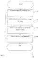
- FIG. 1 illustrates one embodiment of a generalized method 100 for improving power consumption during discontinuous reception (DRX).
- the method adjusts a wake-up time period according to previous performance.
- a user equipment (UE) or other device can configure a wake-up time for a component based on a desired success rate for e.g., decoding a logical channel (such as a physical downlink control channel (PDCCH)).
- a logical channel such as a physical downlink control channel (PDCCH)
- the UE determines its historic performance.
- performance is measured as a function of successful (or alternately unsuccessful) decoding of a signal.
- the UE stores metrics for successful reception of a physical downlink control channel (PDCCH) or a physical downlink shared channel (PDSCH).
- PDCH physical downlink control channel
- PDSCH physical downlink shared channel
- BLER Block Error Rate
- Other common metrics may include without limitation: bit error rates (BER), packet error rates (PER), cyclic redundancy checks (CRC), etc.
- performance is measured as a function of a deviation from an expected value.
- feedback loops continuously monitor an error signal to adjust an output result; this error signal may be calculated as the difference between the input signal and a modified version of the output signal (i.e., filtered and amplified by a gain). If the error signal falls outside of an expected range, the feedback loop will take longer to converge on an appropriate output result.
- the error signal history can be used as a performance metric.
- the time taken to converge to an appropriate output result can be used as a performance metric.
- Performance history may be compared to known or derived values (e.g., an expected value), or alternately performance history may track a change in the value from the previous value (e.g., a so-called "delta" change). Moreover, in some embodiments, performance history may include multiple values over time
- the UE adjusts one or more component wake-up times based on historic performance.
- the component is a tracking loop.
- a tracking loop include for example, frequency tracking loops (FTL), time tracking loops (TTL), and power tracking loops (e.g., automatic gain control (AGC), etc.).
- FTL frequency tracking loops
- TTL time tracking loops
- AGC automatic gain control
- Tracking loop wake-up time is an amount of time allotted to the tracking loop to settle into a usable state. This includes powering the various internal mechanisms of the tracking loop and allowing the mechanisms to reach internal equilibrium.
- a component powers on its internals and allows them to "settle" into their initial states.
- this settling time allows various internals to flush out spurious behavior or transients caused by or related to powering on the device.
- tracking loops may experience some spurious behavior, and oscillate or "ring".
- the component can wake-up in a shorter amount of time if the resulting performance degradation is "intelligently" managed.
- the UE sets a wake-up time to conform to a desired performance based on the historic performance.
- the UE adjusts the tracking loop wake-up time based on the previously stored Block Error Rate (BLER) of the PDCCH and PDSCH. If the BLER was previously acceptable, then the UE can reduce (or leave unchanged) the tracking loop wake-up times. If the BLER was previously unacceptable, then the UE can increase the tracking loop wake-up time. In other embodiments, the UE adjusts the tracking loop wake-up time based on the previously stored feedback loop error value. By continuously adjusting the tracking loop wake-up, the UE the duration of the wake-up procedure may be shortened.
- BLER Block Error Rate
- the designated component powers up according to the adjusted wake-up time. Once the component is powered up, the component measures one or more performance metrics during the DRX time slot, and at step 108 of the method 100, the UE updates its historic performance.
- a cellular radio system includes a network of radio cells each served by a transmitting station, known as a cell site or base station (BS).
- the radio network provides wireless communications service for a plurality of user equipment (UE) transceivers.
- UE user equipment
- the network of BSs working in collaboration allows for wireless service which is greater than the radio coverage provided by a single serving BS.
- the individual BSs are connected to a Core Network, which includes additional controllers for resource management and in some cases access to other network systems (such as the Internet, other cellular networks, etc.).
- FIG. 2 illustrates one exemplary Long Term Evolution (LTE) cellular network 200, with user equipments (UEs) 210, operating within the coverage of the Radio Access Network (RAN) provided by a number of base stations (BSs) 220.
- LTE base stations are commonly referred to as "Enhanced NodeBs" (eNBs).
- eNBs Enhanced NodeBs
- the Radio Access Network (RAN) is the collective body of eNBs.
- the user interfaces to the RAN via the UE, which in many typical usage cases is a cellular phone or smartphone.
- the terms “UE”, ⁇ client device”, and “user device” may include, but are not limited to, cellular telephones, smartphones (such as for example an iPhone TM manufactured by the Assignee hereof), personal computers (PCs), such as for example an iMac TM, Mac Pro TM, Mac Mini TM or Mac Book TM , and minicomputers, whether desktop, laptop, or otherwise, as well as mobile devices such as handheld computers, PDAs, personal media devices (PMDs), such as for example an iPod TM, or any combinations of the foregoing.
- smartphones such as for example an iPhone TM manufactured by the Assignee hereof
- PCs personal computers
- PMDs personal media devices
- iPod TM any combinations of the foregoing.
- Each of the eNBs 220 are directly coupled to the Core Network 230 e.g., via broadband access. Additionally, in some networks the eNBs may coordinate with one another, via secondary access.
- the Core Network 230 provides both routing and service capabilities. For example, a first UE connected to a first eNB can communicate with a second UE connected to a second eNB, via routing through the Core Network 230. Similarly, a UE can access other types of services e.g., the Internet, via the Core Network 230.
- DRX discontinuous reception
- DTX discontinuous transmission
- DRX can be enabled in different network connection states; these network connection states include when the UE has a radio resource connection (RRC), and when the UE is idle.
- RRC radio resource connection
- the UE listens to downlink (DL) packets that follow a specific identifying pattern (e.g., packet header, etc.) that has been determined by the base station (BS).
- BS base station
- the UE periodically looks for a paging message from the BS to determine if the UE needs to connect to the network and acquire the uplink (UL) timing.
- DRX mode operation is specified for two distinct states: (i) RRC_CONNECTED, and (ii) RRC_IDLE.
- DRX mode is enabled during an idle period of the downlink (DL) packet arrival.
- the UE In the RRC_IDLE state, the UE must be paged for DL traffic (according to a paging schedule) or initiate uplink (UL) traffic by requesting a RRC connection with the serving eNB.
- DRX and DTX techniques are used in several wireless technologies including, for example Universal Mobile Telecommunications System (UMTS), LTE (Long-term Evolution), and WiMAX (Worldwide Interoperability for Microwave Access).
- UMTS Universal Mobile Telecommunications System
- LTE Long-term Evolution
- WiMAX Worldwide Interoperability for Microwave Access
- Incipient technologies will support very high data rates by using techniques that consume significant amounts of power during operation. Consequently, reducing transceiver use during inactivity will greatly improve overall transceiver power consumption.
- Existing schemes for DRX are controlled by the BS; i.e., the BS determines the times during DRX transmissions are sent from the BS to the UE; however, the UE independently manages its wake-up procedure to ensure that it will receive these DRX transmissions.
- Preparation time is largely dominated by the constraints of the RF (radio frequency) transceiver and analog baseband components.
- the transceiver requires time to re-enable components (and any associated settling time), "warm-up" clocks, processors, and digital tracking algorithms for e.g., timing, frequency and gain control, etc.
- Most cellular technologies experience dramatic degradation of performance if timing and frequency exceed acceptable limits and in particular, OFDM-based systems are especially sensitive to time and frequency drift.
- cellular devices have been designed around "worst case" component tolerances and scenarios to reduce manufacturing and design complexity while still providing acceptable behavior. For example, existing solutions identify a time that is required to support all components for wake-up (even though many components perform significantly better); the identified value is hardcoded into the device.
- a scheme for improving the wake-up procedure is disclosed that adaptively adjusts the wake-up time for components.
- existing solutions for the RF (radio frequency) and analog baseband component wake-up times are fixed values (based on e.g., component tolerances and/or hardware requirements)
- one exemplary embodiment adaptively adjusts wake-up times of digital tracking algorithms based on key performance metrics from previous DRX cycles, such as DL decoding success rate, residual frequency and timing errors, etc.
- the Enhanced NodeB controls DRX operations using various timers and/or parameters that are communicated to the user equipment (UE).
- UE user equipment
- LTE communications are conducted according to a time schedule that includes frames, subframes, and slots.
- a time schedule that includes frames, subframes, and slots.
- FIG. 3 One such exemplary LTE frame 300 is illustrated in FIG. 3 .
- the UE When the UE has a radio resource connection, the UE can be allocated one or more time slots for communication. If a UE is enabled for DRX operation in RRC connected mode, the UE will wake-up and sleep in accordance with its resource allocations. During RRC idle mode, the UE does not have a radio resource connection. The UE will periodically wake-up to see if it is being paged within a frame of data. If the frame does not have a page for the UE, the UE will go back to sleep.
- a DRX inactivity timer indicates the time in number of consecutive subframes to wait before enabling DRX.
- DRX operation is split into short cycles and long cycles.
- Short DRX cycles and long DRX cycles allow the eNB to adjust the DRX cycles based on ongoing application activity. For example, a UE may initially be placed in a short DRX cycle during brief lulls in activity.
- a DRX short cycle timer determines when to transition to the long DRX cycle; i.e., if the DRX short cycle timer expires without any UE activity, the UE transitions to the long DRX cycle which further reduces power consumption.
- the eNB may release the RRC connection. Once the UE transitions into RRC IDLE state, idle mode DRX is enabled.
- an ON duration timer determines the number of frames the UE can sleep through before reading the downlink (DL) control channel. Commonly used values for the ON duration timer are 1, 2, 3, 4, 5, 6, 8, 10, 20, 30, 40, 50, 60, 80, 100, and 200.
- the UE During idle mode DRX, the UE only needs to monitor one paging occasion (PO) per DRX cycle, which is one subframe.
- PO paging occasion
- FIG. 4 a generalized timeline is shown that depicts the wake-up procedure executed by the UE when preparing for DRX reception.
- the transceiver clock is turned on and warmed up.
- the transceiver clock provides the main clocking for the digital signal processor (DSP) that drives software (SW) and firmware (FW), as well as the application specific integrated circuit (ASIC) baseband hardware.
- DSP digital signal processor
- SW software
- FW firmware
- ASIC application specific integrated circuit
- Analog baseband components may include without limitation: duplexers, diplexers, mixers, analog filters, power amplifiers (PA), analog to digital converters (ADC), and digital to analog converters (DAC), etc., all well known to those of ordinary skill in the radio frequency arts.
- Baseband tracking loops include, for example: a frequency tracking loop (FTL), a time tracking loop (TTL), and automatic gain control (AGC).
- FTL frequency tracking loop
- TTL time tracking loop
- AGC automatic gain control
- the baseband tracking loops are configured to maintain frequency, time, and power control within acceptable tolerances for communicating with the base station (BS).
- BS base station
- the tracking loops track the downlink (DL) carrier frequency errors, timing offsets, and received power variations based on the DL reference signals (RS) (also referred to as "pilot signals").
- RS DL reference signals
- DL processing includes, inter alia, demodulating and decoding of the appropriate data and control channels.
- the radio transceiver demodulates and decodes a Physical Downlink Control Channel (PDCCH); if the UE is so directed (e.g., if the UE is being paged, etc.), then the UE will additionally decode the Physical Downlink Shared Channel (PDSCH) (the PDSCH has both control and data payloads).
- PDCCH Physical Downlink Control Channel
- PDSCH Physical Downlink Shared Channel
- the UE can go back to sleep (410). Most of the transceiver circuitry will be turned off including the RF, digital baseband, and processors. Only a small portion of the circuitry and the low power clock remains powered to maintain coarse tracking of the carrier timing. This "coarse" timing ensures that the timing variation will be limited to a relatively small range that can be corrected during wake-up of the next DRX cycle.
- the UE tracks the frequency error based on the frequency of reference signals (RS) that are transmitted by the eNB.
- RS reference signals
- the frequency error is used as feedback for a frequency rotator. If left unchecked, carrier frequency error degrades the UE's receiver performance; at excessive levels, frequency error affects the orthogonality of the received OFDM (orthogonal frequency division multiplexing) signals, thus causing significant inter-channel interference (ICI) which deteriorates system performance dramatically.
- RS reference signals
- FIG. 5 illustrates one such frequency tracking loop (FTL) using a frequency rotator for frequency compensation.
- the UE performs channel estimation on known reference signals (RS); the channel estimation calculates a channel impulse response (CIR) for each RS.
- CIR channel impulse response
- the channel path is the same for adjacent RS signals on the same antenna (i.e., the CIR is predominantly affected by the wireless channel experienced for each TX-RX antenna pair, and can be assumed to be static within a short time period that is much less than the channel correlation-time). Consequently, a CIR of a first RS with the CIR of an adjacent RS will differ only by a minor difference in phase that is attributable to the carrier frequency error experienced during transmission.
- the phase difference can be determined by correlating the first CIR with the adjacent CIR; the resultant phase difference can be used to calculate the frequency error.
- the frequency error is multiplied by the FTL loop gain ( ⁇ FTL ); the loop gain determines how fast and accurately the loop converges to the correct frequency value. If the loop gain is too large, the loop may track to instantaneous noise instead of the true frequency errors; if the loop gain is too small, it may take a long time to converge to the true frequency error.
- the UE should track the carrier frequency error instead of Doppler frequency shift.
- Doppler frequency shift is dependent on the movement of the UE; thus, Doppler frequency shift has different characteristics than carrier frequency error (which is predominantly caused by component effects).
- the frequency estimation is filtered (e.g., via an infinite impulse response (IIR) filter) to remove Doppler effects, thus providing stable frequency control.
- IIR infinite impulse response
- the TTL tracks the change in transmission time between the UE and the eNB.
- the time delay (or delay spread) is used to determine the optimal window of data samples to process with a Fast Fourier Transform (FFT) to extract the OFDM signaling.
- FFT Fast Fourier Transform
- timing error contributes to overall performance degradation. Large timing errors can cause improper selection of the FFT window, and reduce the overall Carrier-to-interference plus Noise Ratio (CINR) of the received signal.
- CINR Carrier-to-interference plus Noise Ratio
- the FFT window can be selected to span from CP to CP, thus fully encompassing the FFT symbol.
- the FFT window can avoid inter-channel interference (ICI) and inter-symbol-interference ISI, which allows the receiver to completely recover the FFT symbol.
- ICI inter-channel interference
- ISI inter-symbol-interference ISI
- a time tracking loop is illustrated.
- the TTL is configured to optimize the position of the FFT window as a function of the channel multi-path taps, so as to maximize the CINR ratio.
- a timing error is calculated from the channel impulse response (CIR); i.e., how much time shift has the reference signal (RS) CIR changed, in view of the previous RS CIR.
- the timing error is multiplied by a TTL loop gain ( ⁇ TTL ); the loop gain determines how fast and accurately the loop converges to the correct time value. Similar to the FTL loop, the resulting value is filtered, and used as feedback for the FFT window location.
- the receiver automatic gain control (AGC) algorithm is designed to maintain a constant signal power at the input to the demodulator, which is implemented through the mechanism of two loops: an outer loop, and an inner loop.
- the outer loop controls the low-noise amplifier (LNA) gain state in RF (i.e., by increasing or decreasing amplifier gain); the LNA gain state can compensate for coarse gain variations.
- the inner loop estimates and adjusts the digital variable gain control (DVGA) to maintain a constant set-point for the signal power at the input to the demodulator.
- the DVGA can perform fine adjustment in the digital domain.
- the AGC loops are implemented in a similar fashion to the FTL and TTL control loops (i.e., the input is measured for power, filtered and then fed back for adjustment). For illustrative purposes, the AGC loop gains are ⁇ AGC for both inner and outer loops.
- a coarse low power sleep clock remains on during the DRX sleep period to keep track of timing.
- the baseband tracking circuitry powers on from the completely powered off state based on the coarse low power sleep clock. For this reason, the initial timing error and frequency error can be large at the start of DRX wake-up. If the tracking loops do not converge within a reasonable range, the DL packets cannot be properly demodulated and decoded. Also, since the wireless channel can vary dramatically from the last wake-up period, there may be very large power swings in waking the receiver back up.
- the time budget for waking up the baseband tracking loops is based on the worst-case component tolerances, so as to ensure successful decoding of the downlink (DL) transmissions during the DRX cycle.
- the adaptive wake-up of tracking algorithms during the DRX operation is based on physical layer metrics from previous DRX cycles.
- the time budgeted for waking up the baseband tracking loops is based on the block error rates (BLER) of physical downlink control channel and physical downlink shared channel decoded during the previous DRX cycle.
- BLER block error rates
- various disclosed embodiments are directed to adaptively shortening the time for waking up components based on the likelihood of successfully decoding a message (rather than conforming to a fixed e.g., worst-case component tolerance).
- a fixed e.g., worst-case component tolerance e.g., worst-case component tolerance
- the time budgeted for wake-up is based on a decoding success ratio (e.g., the BLER) for the Physical Downlink Control Channel (PDCCH) and Physical Downlink Shared Channel (PDSCH) during previous DRX cycles.
- a decoding success ratio e.g., the BLER
- the baseband tracking loops can be shortened. If the ratio of successful decodes falls within a target band, then time values for the baseband tracking loop values are sufficient. Otherwise, if the ratio of successful decodes exceeds acceptable rates, then the baseband tracking loops need more time to warm up.
- the residual tracking loop error for the previous DRX cycle can be used to determine the approximate amount of time for warm up. For example, if the tracking loops were making significant error corrections during previous tracking loops, then the tracking loops should be allotted more warm-up time. If the tracking loops do not accumulate significant errors, then the existing tracking loop performance is satisfactory, and tracking loop time may be shortened.
- energy estimation from previous DRX cycles can be used to determine if (for example) the low noise amplifier (LNA) is operating in a non-linear region that may lead to saturation.
- LNA low noise amplifier
- the signal quality references can also be used as a metric for adaptive wake-up. For example, a higher estimated Signal to Noise Ratio (SNR) at the end of the previous DRX cycle indicates that the tracking loops had been operating within acceptable limits, and the wake-up time of the tracking loops in the current DRX cycle can be reduced accordingly. Similarly, a lower estimated SNR at the end of the previous DRX cycle may indicate that the tracking loop time needs to be increased.
- SNR Signal to Noise Ratio
- FIGS. 7 and 8 two different schemes for configuring baseband tracking loops are disclosed.
- FIG. 7 illustrates a first scheme for configuring a baseband tracking loop.
- the baseband tracking loop can be parameterized with a time constant value that is derived from the loop gain to represent how long the loop takes to stabilize.
- a baseband tracking loop that has a one-tap infinite impulse response (IIR) loop is configured with a time constant that is the inverse of the loop gain. It is worth noting that configuring the baseband tracking loop for a runtime that is significantly less than the time constant may create sizable residual errors.
- IIR infinite impulse response
- the UE adaptively reduces the wake-up time for the tracking loops based on a desired success rate for the physical Downlink shared channel (PDSCH) represented as P% (95% for example).
- the baseband tracking loops are set to a wake-up time value (e.g., t * FTL , t * TTL , and t * AGC for the frequency tracking loop (FTL), time tracking loop (TTL) and automatic gain control (AGC), respectively) during each DRX cycle.
- a wake-up time value e.g., t * FTL , t * TTL , and t * AGC for the frequency tracking loop (FTL), time tracking loop (TTL) and automatic gain control (AGC), respectively.
- FTL frequency tracking loop
- TTL time tracking loop
- AGC automatic gain control
- the UE initializes the loop running times (e.g., t FTL , t TTL , and t AGC ) to the corresponding times (t * FTL , t * TTL , and t * AGC ) which correspond to a P% success rate for the PDSCH.
- loop running times e.g., t FTL , t TTL , and t AGC
- t * FTL , t * TTL , and t * AGC may be initialized from pre-determined values, historically determined values, calculated values, etc.
- the UE decodes the PDCCH and PDSCH.
- a running count of errors e.g., bit error rate (BER), packet error rate (PER), block error rate (BLER), etc.
- P pre a success rate
- the PDCCH and PDSCH experience some degree of error, the PDCCH and PDSCH are robustly coded and can be correctly received in the presence of errors.
- the PDCCH and PDSCH can only be received successfully if the tracking loops are operating properly (where the wake-up time was sufficient).
- the UE executes one of steps 706, 708 and 710, based on the previously stored success rate.
- the values for t * FTL , t * TTL , and t * AGC are adjusted based on the stored success rate (Pp re %) being greater than the desired success rate ( P data % ) .
- the UE can reduce the tracking loop wake-up time.
- the wake-up times for the FTL, TTL. and AGC are reduced by a factor ⁇ ⁇ 1.
- t FTL ⁇ ⁇ t FTL
- t TTL ⁇ ⁇ t TTL
- t AGC ⁇ ⁇ t AGC ; where: ⁇ ⁇ 1.
- the values for t * FTL, t * TTL , and t * AGC are adjusted based on the stored success rate ( P pre % ) being lower than the desired success rate ( P data % ). In other words, if the previous performance is worse than is required, the UE should increase the tracking loop wake-up time. As shown in EQN. 2, the wake-up times for the FTL, TTL, and AGC are increased by a factor ⁇ > 1.
- t FTL ⁇ ⁇ t FTL
- t TTL ⁇ ⁇ t TTL
- t AGC ⁇ ⁇ t AGC ; where. ⁇ >1.
- the values for t * FTL , t * TTL , and t * AGC are left unchanged if the stored success rate ( P pre %) equals the desired success rate ( P data % ). It is additionally noted that minor variations in success rate may be considered negligible. Thus, in some cases if the stored success rate is within a tolerable range of the desired success rate, the UE does not adjust the tracking loop times.
- the parameters ⁇ and ⁇ can be different for different DRX modes. For example, if errors are detected in idle mode DRX, then the UE may opt to spend more time in wake-up to recover for the next DRX cycle, whereas for connected mode DRX the UE can be more forgiving.
- the foregoing equations (EQN. 1, EQN. 2) have used proportional adjustment (a multiplier), in other variations the adjustment may be fixed (e.g., increment, decrement), a non-linear function (e.g., a look-up table), etc. Other practical limitations may also be considered. For example, in certain systems, the tracking loop wake-up time may be kept within a reasonable range by using an upper and a lower bounded value.
- the residual frequency and timing errors from previous DRX cycles is used to determine an appropriate adjustment to the tracking loop running time for the current DRX cycle.
- the wake-up time can be increased for larger residual errors or decreased for smaller residual errors.
- the residual frequency and timing errors are captured from the feedback loop process (as opposed to an error rate that is determined during decoding). For example, based on empirical data (e.g., historical data) of DRX performance, a residual expected frequency and timing errors ( f Res , t Res ) of the baseband tracking loops correspond to a PDSCH decoding success rate that exceeds P data %.
- the UE initializes the wake-up loop times (i.e., t FTL , t TTL are set to the initial values T * FTL , t * TTL ) ⁇
- the UE determines a residual frequency and timing error ( f R es, t Re s ).
- the UE also retrieves the expected residual frequency and timing errors of corresponding to the PDSCH decoding success rate P dara % to determine the appropriate adjustment.
- the UE executes one of steps 806, 808 and 810, based on the previously stored residual frequency and timing error.
- step 806 if both frequency and timing residual errors are smaller than the expected residual errors ( f R es ⁇ f Res and t Res ⁇ t Res ), then the UE can decrease the tracking loop wake-up times (see for example, EQN. 1).
- step 808 if either the frequency or the timing residual errors are greater than the expected residual errors f Res > f Res or t Res > t Res then the UE must increase the tracking loop wake-up times (see for example, EQN. 2).
- the wake-up values are left unchanged if the stored success rate residual errors equal or are within an acceptable tolerance of the expected values.
- the adaptive wake-up algorithm can be optimized by jointly using residual loop errors and success (or error rates) from previous DRX cycles.
- Such a hybridized scheme i.e., of the first and second schemes of FIG. 7 and FIG. 8
- the changes to loop wake-up times may be different according to different thresholds.
- the loop wake-up time increment may be increased when the frequency and timing errors are greater than a first upper threshold.
- the loop wake-up time increments can be decreased when the frequency and timing errors are smaller than a second lower threshold.
- the amount of the loop gain increase or decrease can be determined by calculating the time constant that is needed to pull-in the errors within the current DRX cycle.
- FIG. 9 an exemplary user device apparatus 900 with reduced power consumption during discontinuous reception is illustrated. While one specific device configuration and layout is shown and discussed herein, it is recognized that many other configurations may be readily implemented by one of ordinary skill given the present disclosure, the apparatus 900 of FIG. 9 being merely illustrative of the broader principles of the present disclosure.
- the apparatus 900 of FIG. 9 includes one or more radio transceivers 902, a computer readable memory 904, and a processing subsystem 906.
- the processing subsystem 906 includes one or more of central processing units (CPU) or digital processors, such as a microprocessor, digital signal processor, field-programmable gate array, RISC core, or plurality of processing components mounted on one or more substrates.
- the processing subsystem is coupled to computer readable memory 904, which may include for example SRAM, FLASH, SDRAM, and/or HDD (Hard Disk Drive) components.
- computer readable memory 904 may include for example SRAM, FLASH, SDRAM, and/or HDD (Hard Disk Drive) components.
- the term "memory” includes any type of integrated circuit or other storage device adapted for storing digital data including, without limitation, ROM. PROM, EEPROM, DRAM, SDRAM, DDR/2 SDRAM, EDO/FPMS, RLDRAM, SRAM, "flash” memory (e.g., NAND/NOR), and PSRAM.
- the processing subsystem may also comprise additional co-processors, such as a dedicated graphics accelerator, network processor (NP), or audio/video processor.
- processing subsystem 906 includes discrete components; however, it is understood that in some embodiments they may be consolidated or fashioned in a SoC (system-on-chip) configuration.
- the memory is configured to store performance information.
- Performance information may broadly include information indicative of successful (or alternately unsuccessful) decoding of a signal.
- performance information include metrics for successful reception of a physical downlink control channel (PDCCH) or a physical downlink shared channel (PDSCH).
- Common metrics may include without limitation: block error rates (BLER), bit error rates (BER), packet error rates (PER), cyclic redundancy checks (CRC), etc.
- the processing subsystem 906 is adapted to receive one or more data streams from a radio transceiver 902.
- the radio transceiver in this exemplary embodiment generally comprises a cellular radio transceiver with one or more components having an adjustable wake-up time.
- components include for example: tracking loops 902A, clocks 902B, RF components 902C and analog baseband components 902D.
- tracking loops include, without limitation, time tracking loops, frequency tracking loops (e.g., automatic frequency control (AFC)), gain tracking loops (e.g., automatic gain control (AGC)), etc.
- AFC automatic frequency control
- AGC automatic gain control
- Clock components may include e.g., crystal oscillators (XO), voltage controlled XO (VCXO), temperature controlled XO (TCXO), and VCTCXO, etc.
- XO crystal oscillators
- VCXO voltage controlled XO
- TCXO temperature controlled XO
- RF and analog baseband components may include without limitation: duplexers, diplexers, mixers, analog filters, power amplifiers (PA), analog to digital converters (ADC), and digital to analog converters (DAC), etc.
Landscapes
- Engineering & Computer Science (AREA)
- Computer Networks & Wireless Communication (AREA)
- Signal Processing (AREA)
- Mobile Radio Communication Systems (AREA)
Claims (10)
- Verfahren zum adaptiven Verwalten einer Vielzahl von Beobachtungsschleifenkomponenten einer mobilen Hochfrequenzkommunikationsvorrichtung, wobei das Verfahren umfasst:Speichern eines Aufwachzeitintervalls für jede der Vielzahl von Beobachtungsschleifenkomponenten in einem Speicher in der mobilen Hochfrequenzkommunikationsvorrichtung, wobei die Vielzahl von Überwachungsschleifenkomponenten zumindest zwei aus einer Zeitbeobachtungsschleifen, time tracking loop, TTL,-Komponente, einer Frequenzbeobachtungsschleifen, frequency tracking loop, FTL,-Komponente und einer automatischen Verstärkungssteuerungs- , automatic gain control, AGC,-Komponente umfasst; undfür jeden einer Vielzahl von diskontinuierlichen Empfangs ,dicontinuous reception, DRX,-Zyklen:Initialisieren jeder der Überwachungsschleifenkomponenten unter Verwendung des entsprechenden Aufwachzeitintervalls, so dass die entsprechende Beobachtungsschleifenkomponente eingeschaltet wird für eine Empfangsperiode während dem DRX-Zyklus;Empfangen von Daten während der Empfangsperiode;Messen von Leistungsdaten für die Daten, die während der Empfangsperiode empfangen wurden; undAktualisieren der Aufwachzeitintervalle von jeder aus der Vielzahl von Beobachtungsschleifenkomponenten basierend auf den Leistungsdaten.
- Verfahren nach Anspruch 1, wobei die Leistungsdaten eine Blockfehlerrate, block error rate, BLER, umfassen.
- Verfahren nach Anspruch 1, wobei die Aufwachzeitintervalle durch eine Multiplikation mit einem Skalierungsfaktor angepasst sind.
- Verfahren nach Anspruch 1, wobei die Aufwachzeitintervalle durch eine Addition oder Subtraktion eines Inkrementierfaktors angepasst sind.
- Verfahren nach Anspruch 1, wobei die Aktualisierung der Aufwachzeitintervalle basierend auf den Leistungsdaten Erhöhen der Aufwachzeitintervalle beinhaltet, wenn die Leistungsdaten angeben, dass die Leistung unter einer Leistungsschwelle ist, und Verringern der Aufwachzeitintervalle beinhaltet, wenn die Leistungsdaten angeben, dass die Leistung über der Leistungsschwelle ist.
- Long term evolution, LTE,-fähige drahtlose mobile Netzwerkbenutzerausrüstungs-, UE, Hochfrequenzkommunikationsvorrichtung umfassend:einen Prozessor;eine drahtlose Schnittstelle; undLeistungsverwaltungslogik in Kommunikation mit dem Prozessor und der drahtlosen Schnittstelle und konfiguriert zum:Initialisieren einer Vielzahl von Beobachtungsschleifenroutinen, wobei jede Initialisierung durch ein Aufwachzeitintervall gekennzeichnet ist, wobei die Vielzahl von Beobachtungsschleifenroutinen zumindest zwei aus einer Zeitbeobachtungsschleifen, time tracking loop, TTL,-Routine, einer Frequenzbeobachtungsschleifen, frequency tracking loop, FTL,-Routine undeiner automatischen Verstärkungssteuerungs, automatic gain control, AGC,- Routine umfassen;Dekodieren eines logischen Kanals, der mit dem drahtlosen Netzwerk assoziiert ist;Bestimmen einer Fehlermessung, die mit dem Dekodieren des logischen Kanals assoziiert ist; undbasierend auf der Fehlermessung, die geringer ist als ein Zielwert, Reduzieren der Aufwachzeitintervalle für jede aus der Vielzahl von Beobachtungsschleifenroutinen.
- Vorrichtung nach Anspruch 6, wobei die Leistungsverwaltungslogik ferner konfiguriert ist, wenn die Fehlermessung größer als der Zielwert ist, zum Erhöhen der Aufwachzeitintervalle.
- Vorrichtung nach Anspruch 6, wobei der logische Kanal einen aus einem physischen Downlink-Steuerungskanal, physical downlink control channel, PDCCH, oder einem physischen geteilten Downlink-Kanal, physical downlink shared channel, PDSCH umfasst.
- Vorrichtung nach Anspruch 8, wobei die Fehlermessung eines aus einer Blockfehlerrate, block error rate, BLER, einer Bit-Fehlerrate, bit error rate, BER, einer Paket-Fehlerrate, packet error rate, PER, und einer zyklischen Redundanzüberwachung, cyclic redundancy checks, CRC, umfasst.
- Computer-lesbare Vorrichtung, die eine Vielzahl von Computer-lesbaren Anweisungen darauf gespeichert hat, wobei die Anweisungen konfiguriert sind um, wenn sie durch einen Prozessor ausgeführt werden, eine mobile Vorrichtung dazu zu veranlassen, das Verfahren nach irgendeinem der Ansprüche 1 bis 5 durchzuführen.
Applications Claiming Priority (3)
| Application Number | Priority Date | Filing Date | Title |
|---|---|---|---|
| US201261585207P | 2012-01-10 | 2012-01-10 | |
| US13/623,807 US9686750B2 (en) | 2012-01-10 | 2012-09-20 | Methods and apparatus for power consumption management during discontinuous reception |
| PCT/US2013/020887 WO2013106471A1 (en) | 2012-01-10 | 2013-01-09 | Methods and apparatus for power consumption management during discontinuous reception |
Publications (2)
| Publication Number | Publication Date |
|---|---|
| EP2803231A1 EP2803231A1 (de) | 2014-11-19 |
| EP2803231B1 true EP2803231B1 (de) | 2016-06-29 |
Family
ID=48743860
Family Applications (1)
| Application Number | Title | Priority Date | Filing Date |
|---|---|---|---|
| EP13707934.9A Not-in-force EP2803231B1 (de) | 2012-01-10 | 2013-01-09 | Verfahren und vorrichtung zur stromverbrauchssteuerung während eines diskontinuierlichen empfangs |
Country Status (7)
| Country | Link |
|---|---|
| US (1) | US9686750B2 (de) |
| EP (1) | EP2803231B1 (de) |
| JP (1) | JP5893168B2 (de) |
| KR (1) | KR101599175B1 (de) |
| CN (1) | CN104160755B (de) |
| TW (1) | TWI520640B (de) |
| WO (1) | WO2013106471A1 (de) |
Families Citing this family (41)
| Publication number | Priority date | Publication date | Assignee | Title |
|---|---|---|---|---|
| US9264278B2 (en) | 2012-10-19 | 2016-02-16 | Apple Inc. | Robust scalable and adaptive frequency estimation and frequency tracking for wireless systems |
| US9179407B2 (en) * | 2012-12-10 | 2015-11-03 | Broadcom Corporation | Selective notification of DRX parameter |
| US9894610B2 (en) * | 2013-05-09 | 2018-02-13 | Lg Electronics Inc. | Method for monitoring on durations in a wireless communication system and a device therefor |
| WO2014194928A1 (en) * | 2013-06-03 | 2014-12-11 | Telefonaktiebolaget L M Ericsson (Publ) | Distortion suppression for wireless transmission |
| US9986582B2 (en) * | 2013-08-30 | 2018-05-29 | Qualcomm Incorporated | Determination of communication control parameter based on communication schedule |
| US9402273B2 (en) | 2013-12-23 | 2016-07-26 | Qualcomm Incorporated | DRX wakeup rule in an eICIC environment |
| US9398633B2 (en) | 2014-03-27 | 2016-07-19 | Qualcomm Incorporated | Methods and apparatus for low power tracking of network system timing for long paging cycles |
| US10051575B2 (en) * | 2014-07-01 | 2018-08-14 | Blackberry Limited | Adaptively determining a wakeup period |
| US20160014695A1 (en) * | 2014-07-11 | 2016-01-14 | Qualcomm Incorporated | Drx power usage by dynamically adjusting a warmup period |
| RU2017113718A (ru) * | 2014-09-24 | 2018-10-24 | Хуавей Текнолоджиз Ко., Лтд. | Устройство связи и способ прерывистой передачи |
| US9872252B1 (en) * | 2016-09-30 | 2018-01-16 | Qualcomm Incorporated | Discontinuous reception mode with multiple-stage wake-up |
| US11310740B2 (en) | 2014-11-04 | 2022-04-19 | Qualcomm Incorporated | Discontinuous reception mode with two-stage wake-up |
| US9980313B2 (en) * | 2014-12-16 | 2018-05-22 | Intel IP Corporation | Radio communication device and method for operation thereof |
| JP6223388B2 (ja) * | 2015-06-25 | 2017-11-01 | 京セラ株式会社 | 通信装置 |
| CN106879002B (zh) * | 2015-12-11 | 2020-03-20 | 北京展讯高科通信技术有限公司 | 一种数据处理的方法及装置 |
| DE102015122431A1 (de) * | 2015-12-21 | 2017-06-22 | Intel IP Corporation | Kommunikationsvorrichtung und Verfahren zum Durchführen von Funkkommunikation |
| US10536868B2 (en) | 2016-02-29 | 2020-01-14 | Samsung Electronics Co., Ltd. | Method and apparatus for performing measurement in wireless communication system |
| US10432378B2 (en) * | 2016-09-30 | 2019-10-01 | Qualcomm Incorporated | Use of reference signals to improve user equipment (UE) warm-up before transitioning from an OFF duration of the UE to an on duration of the UE with respect to a radio frequency spectrum band |
| CN106931993B (zh) * | 2017-03-02 | 2019-06-07 | 西北工业大学 | 一种量测窗长自适应滑动的时变参数估计方法 |
| KR102313704B1 (ko) * | 2017-05-04 | 2021-10-18 | 광동 오포 모바일 텔레커뮤니케이션즈 코포레이션 리미티드 | 불연속 수신을 위한 방법과 장치 |
| RU2735332C1 (ru) * | 2017-08-25 | 2020-10-30 | Гуандун Оппо Мобайл Телекоммьюникейшнз Корп., Лтд. | Способ прерывистого приема, терминал и сетевое устройство |
| US11540218B2 (en) * | 2018-02-26 | 2022-12-27 | Telefonaktiebolaget Lm Ericsson (Publ) | Method for determining timing of transmission, network node, and computer program |
| US11379708B2 (en) * | 2018-08-09 | 2022-07-05 | Nvidia Corporation | Techniques for efficiently operating a processing system based on energy characteristics of instructions and machine learning |
| EP3850892B1 (de) * | 2018-09-14 | 2022-08-24 | Telefonaktiebolaget LM Ericsson (publ) | Übertragungssystemsteuerung |
| CN119211964A (zh) * | 2018-09-27 | 2024-12-27 | 苹果公司 | 空闲和不活动状态下的用户装备的寻呼接收 |
| KR102442912B1 (ko) * | 2018-09-28 | 2022-09-13 | 텔레폰악티에볼라겟엘엠에릭슨(펍) | 연결 모드에서의 무선 디바이스를 위한 웨이크업 다운링크 제어 정보(dci) |
| US11038727B2 (en) * | 2018-11-08 | 2021-06-15 | Qualcomm Incorporated | User equipment receiver processing for multi-transmit-receive-point communication |
| US11178618B2 (en) * | 2019-01-10 | 2021-11-16 | Qualcomm Incorporated | Adaptation of power parameter values in discontinuous reception |
| WO2020224898A1 (en) * | 2019-05-03 | 2020-11-12 | Telefonaktiebolaget Lm Ericsson (Publ) | Wireless device-autonomous procedures for missed-wake up signals |
| WO2021004600A1 (en) * | 2019-07-05 | 2021-01-14 | Telefonaktiebolaget Lm Ericsson (Publ) | Wireless device |
| CN110489169B (zh) * | 2019-08-06 | 2021-10-19 | 晶晨半导体(上海)股份有限公司 | 一种片上系统的存储器快速启动方法 |
| US11172533B2 (en) | 2019-08-29 | 2021-11-09 | Qualcomm Incorporated | Methods and apparatus to facilitate multi-tasking and smart location selection during connected-mode discontinuous reception mode |
| CN112787731B (zh) * | 2019-11-08 | 2022-05-24 | 大唐移动通信设备有限公司 | 终端省电性能的测试方法、装置、网络模拟器及终端 |
| CN111246550A (zh) * | 2020-01-07 | 2020-06-05 | 维沃移动通信有限公司 | 电子设备状态调整方法以及电子设备 |
| EP4223022A1 (de) | 2020-09-30 | 2023-08-09 | Qualcomm Incorporated | Adaptive verfolgungsschleifenaktualisierungen in benutzergeräten |
| CN112260860B (zh) * | 2020-10-09 | 2024-03-29 | 北京小米松果电子有限公司 | 设备调试方法及装置、电子设备及存储介质 |
| EP4236486A4 (de) * | 2020-10-20 | 2024-07-24 | Beijing Xiaomi Mobile Software Co., Ltd. | Verbindungsaufbauverfahren und -vorrichtung sowie kommunikationsvorrichtung und speichermedium |
| WO2023128057A1 (en) * | 2022-01-03 | 2023-07-06 | Samsung Electronics Co., Ltd. | Method and apparatus for power management of access point |
| US12143953B2 (en) * | 2022-04-01 | 2024-11-12 | Qualcomm Incorporated | Techniques for power reduction in single subscriber identity module (SSIM) and multi-sim (MSIM) 5G new radio (NR) standalone (SA) user equipment (UE) devices |
| US20250358893A1 (en) * | 2022-08-02 | 2025-11-20 | Qualcomm Incorporated | Adjustment indications and associated acknowledgements for extended reality (xr) communications |
| CN121805676A (zh) * | 2026-03-11 | 2026-04-07 | 中国铁塔股份有限公司天津市分公司 | 一种用于频谱探测设备的能效自适应调控装置及方法 |
Family Cites Families (16)
| Publication number | Priority date | Publication date | Assignee | Title |
|---|---|---|---|---|
| US5712867A (en) * | 1992-10-15 | 1998-01-27 | Nexus 1994 Limited | Two-way paging apparatus having highly accurate frequency hopping synchronization |
| US5530911A (en) | 1994-07-15 | 1996-06-25 | Motorola, Inc. | Method and apparatus for battery drain reduction by adjusting for dynamic changes of receiver warm-up time |
| JP2872057B2 (ja) | 1994-11-24 | 1999-03-17 | 日本電気株式会社 | 無線選択呼出受信機 |
| US7558333B2 (en) * | 2003-10-08 | 2009-07-07 | Qingchong Liu | Distortion tolerant linear phase modulations |
| US8027373B2 (en) * | 2005-09-15 | 2011-09-27 | Qualcomm Incorporated | Quick detection of signaling in a wireless communication system |
| US8787840B2 (en) * | 2006-05-10 | 2014-07-22 | Robert Bosch Gmbh | Method and system employing wideband signals for RF wakeup |
| US8346313B2 (en) | 2006-08-01 | 2013-01-01 | Qualcomm Incorporated | Dynamic warm-up time for a wireless device in idle mode |
| JP2008149542A (ja) | 2006-12-15 | 2008-07-03 | Fujifilm Corp | インクジェット画像形成方法、形成装置およびインク組成物 |
| US8094574B2 (en) * | 2007-08-20 | 2012-01-10 | Marvell International Ltd. | Method and apparatus for wireless receiving |
| US8576757B2 (en) | 2007-12-12 | 2013-11-05 | Qualcomm Incorporated | Dynamic adjustment of setup time based on paging performance |
| US8170515B2 (en) * | 2008-05-21 | 2012-05-01 | Medtronic, Inc. | Method and apparatus for the phased detection of a signal including a frequency deviation detection phase |
| CN105721122B (zh) * | 2008-09-22 | 2020-06-05 | 交互数字专利控股公司 | 检测无线电链路失败的方法及设备 |
| US8457112B2 (en) * | 2008-11-07 | 2013-06-04 | Motorola Mobility Llc | Radio link performance prediction in wireless communication terminal |
| US8625724B2 (en) * | 2009-03-10 | 2014-01-07 | Qualcomm Incorporated | Adaptive tracking steps for time and frequency tracking loops |
| US20100317374A1 (en) * | 2009-06-11 | 2010-12-16 | Yaron Alpert | Apparatus for and method of managing paging interval access on a mobile station |
| US8554251B2 (en) | 2009-06-29 | 2013-10-08 | Qualcomm Incorporated | Device, method, and apparatus for offline discontinuous reception (DRX) processing in cellular systems |
-
2012
- 2012-09-20 US US13/623,807 patent/US9686750B2/en not_active Expired - Fee Related
-
2013
- 2013-01-09 JP JP2014552270A patent/JP5893168B2/ja not_active Expired - Fee Related
- 2013-01-09 CN CN201380012688.9A patent/CN104160755B/zh not_active Expired - Fee Related
- 2013-01-09 KR KR1020147022174A patent/KR101599175B1/ko not_active Expired - Fee Related
- 2013-01-09 EP EP13707934.9A patent/EP2803231B1/de not_active Not-in-force
- 2013-01-09 WO PCT/US2013/020887 patent/WO2013106471A1/en not_active Ceased
- 2013-01-10 TW TW102100958A patent/TWI520640B/zh not_active IP Right Cessation
Also Published As
| Publication number | Publication date |
|---|---|
| JP2015507426A (ja) | 2015-03-05 |
| WO2013106471A1 (en) | 2013-07-18 |
| TW201338593A (zh) | 2013-09-16 |
| US20130176873A1 (en) | 2013-07-11 |
| US9686750B2 (en) | 2017-06-20 |
| CN104160755B (zh) | 2018-07-13 |
| JP5893168B2 (ja) | 2016-03-23 |
| CN104160755A (zh) | 2014-11-19 |
| KR20140111339A (ko) | 2014-09-18 |
| EP2803231A1 (de) | 2014-11-19 |
| TWI520640B (zh) | 2016-02-01 |
| KR101599175B1 (ko) | 2016-03-02 |
Similar Documents
| Publication | Publication Date | Title |
|---|---|---|
| EP2803231B1 (de) | Verfahren und vorrichtung zur stromverbrauchssteuerung während eines diskontinuierlichen empfangs | |
| TWI758474B (zh) | 用於新無線電中的多狀態drx的技術 | |
| CN114258732B (zh) | 用于监控节电信令的物理下行控制通道的方法及相关设备 | |
| EP3150006B1 (de) | Adaptive steuerung von hf-niederstrom-modi in einem mehrratigen drahtlossystem mittels mcs-wert | |
| JP5237436B2 (ja) | アクセス端末においてスリープ期間中に生じるドリフトを補償すること | |
| US9374259B2 (en) | Physical downlink control channel decoding | |
| US10051575B2 (en) | Adaptively determining a wakeup period | |
| US9503978B2 (en) | Timing resolution for devices with long sleep cycles | |
| US20160323930A1 (en) | Adaptive physical layer warm-up for lte tdd c-drx power optimization | |
| EP2805551B1 (de) | Verfahren und vorrichtung für adaptive empfängermodusauswahl während eines unterbrochenen empfangs | |
| KR20140109773A (ko) | 무선 통신 시스템에서 전송 구간 단위 전력 절약 장치 및 방법 | |
| US9967112B2 (en) | Apparatus and methods for adaptively resuming radio channel estimation | |
| EP2829132A1 (de) | Verfahren und vorrichtung zur parametereinstellung | |
| US20160014695A1 (en) | Drx power usage by dynamically adjusting a warmup period | |
| US12192918B2 (en) | Techniques for bandwidth part switching adaptive voltage and clock configuration | |
| WO2022265626A1 (en) | Apparatus and method for user equipment power saving in semi-persistent scheduling transmission |
Legal Events
| Date | Code | Title | Description |
|---|---|---|---|
| PUAI | Public reference made under article 153(3) epc to a published international application that has entered the european phase |
Free format text: ORIGINAL CODE: 0009012 |
|
| 17P | Request for examination filed |
Effective date: 20140617 |
|
| AK | Designated contracting states |
Kind code of ref document: A1 Designated state(s): AL AT BE BG CH CY CZ DE DK EE ES FI FR GB GR HR HU IE IS IT LI LT LU LV MC MK MT NL NO PL PT RO RS SE SI SK SM TR |
|
| DAX | Request for extension of the european patent (deleted) | ||
| 17Q | First examination report despatched |
Effective date: 20150511 |
|
| GRAP | Despatch of communication of intention to grant a patent |
Free format text: ORIGINAL CODE: EPIDOSNIGR1 |
|
| INTG | Intention to grant announced |
Effective date: 20160122 |
|
| GRAS | Grant fee paid |
Free format text: ORIGINAL CODE: EPIDOSNIGR3 |
|
| GRAA | (expected) grant |
Free format text: ORIGINAL CODE: 0009210 |
|
| AK | Designated contracting states |
Kind code of ref document: B1 Designated state(s): AL AT BE BG CH CY CZ DE DK EE ES FI FR GB GR HR HU IE IS IT LI LT LU LV MC MK MT NL NO PL PT RO RS SE SI SK SM TR |
|
| REG | Reference to a national code |
Ref country code: GB Ref legal event code: FG4D |
|
| REG | Reference to a national code |
Ref country code: CH Ref legal event code: EP |
|
| REG | Reference to a national code |
Ref country code: AT Ref legal event code: REF Ref document number: 809957 Country of ref document: AT Kind code of ref document: T Effective date: 20160715 |
|
| REG | Reference to a national code |
Ref country code: IE Ref legal event code: FG4D |
|
| REG | Reference to a national code |
Ref country code: DE Ref legal event code: R096 Ref document number: 602013008917 Country of ref document: DE |
|
| REG | Reference to a national code |
Ref country code: LT Ref legal event code: MG4D |
|
| PG25 | Lapsed in a contracting state [announced via postgrant information from national office to epo] |
Ref country code: FI Free format text: LAPSE BECAUSE OF FAILURE TO SUBMIT A TRANSLATION OF THE DESCRIPTION OR TO PAY THE FEE WITHIN THE PRESCRIBED TIME-LIMIT Effective date: 20160629 Ref country code: NO Free format text: LAPSE BECAUSE OF FAILURE TO SUBMIT A TRANSLATION OF THE DESCRIPTION OR TO PAY THE FEE WITHIN THE PRESCRIBED TIME-LIMIT Effective date: 20160929 Ref country code: LT Free format text: LAPSE BECAUSE OF FAILURE TO SUBMIT A TRANSLATION OF THE DESCRIPTION OR TO PAY THE FEE WITHIN THE PRESCRIBED TIME-LIMIT Effective date: 20160629 |
|
| REG | Reference to a national code |
Ref country code: NL Ref legal event code: MP Effective date: 20160629 |
|
| PG25 | Lapsed in a contracting state [announced via postgrant information from national office to epo] |
Ref country code: HR Free format text: LAPSE BECAUSE OF FAILURE TO SUBMIT A TRANSLATION OF THE DESCRIPTION OR TO PAY THE FEE WITHIN THE PRESCRIBED TIME-LIMIT Effective date: 20160629 Ref country code: GR Free format text: LAPSE BECAUSE OF FAILURE TO SUBMIT A TRANSLATION OF THE DESCRIPTION OR TO PAY THE FEE WITHIN THE PRESCRIBED TIME-LIMIT Effective date: 20160930 Ref country code: RS Free format text: LAPSE BECAUSE OF FAILURE TO SUBMIT A TRANSLATION OF THE DESCRIPTION OR TO PAY THE FEE WITHIN THE PRESCRIBED TIME-LIMIT Effective date: 20160629 Ref country code: NL Free format text: LAPSE BECAUSE OF FAILURE TO SUBMIT A TRANSLATION OF THE DESCRIPTION OR TO PAY THE FEE WITHIN THE PRESCRIBED TIME-LIMIT Effective date: 20160629 Ref country code: SE Free format text: LAPSE BECAUSE OF FAILURE TO SUBMIT A TRANSLATION OF THE DESCRIPTION OR TO PAY THE FEE WITHIN THE PRESCRIBED TIME-LIMIT Effective date: 20160629 Ref country code: LV Free format text: LAPSE BECAUSE OF FAILURE TO SUBMIT A TRANSLATION OF THE DESCRIPTION OR TO PAY THE FEE WITHIN THE PRESCRIBED TIME-LIMIT Effective date: 20160629 |
|
| REG | Reference to a national code |
Ref country code: AT Ref legal event code: MK05 Ref document number: 809957 Country of ref document: AT Kind code of ref document: T Effective date: 20160629 |
|
| PG25 | Lapsed in a contracting state [announced via postgrant information from national office to epo] |
Ref country code: RO Free format text: LAPSE BECAUSE OF FAILURE TO SUBMIT A TRANSLATION OF THE DESCRIPTION OR TO PAY THE FEE WITHIN THE PRESCRIBED TIME-LIMIT Effective date: 20160629 Ref country code: SK Free format text: LAPSE BECAUSE OF FAILURE TO SUBMIT A TRANSLATION OF THE DESCRIPTION OR TO PAY THE FEE WITHIN THE PRESCRIBED TIME-LIMIT Effective date: 20160629 Ref country code: EE Free format text: LAPSE BECAUSE OF FAILURE TO SUBMIT A TRANSLATION OF THE DESCRIPTION OR TO PAY THE FEE WITHIN THE PRESCRIBED TIME-LIMIT Effective date: 20160629 Ref country code: IS Free format text: LAPSE BECAUSE OF FAILURE TO SUBMIT A TRANSLATION OF THE DESCRIPTION OR TO PAY THE FEE WITHIN THE PRESCRIBED TIME-LIMIT Effective date: 20161029 Ref country code: CZ Free format text: LAPSE BECAUSE OF FAILURE TO SUBMIT A TRANSLATION OF THE DESCRIPTION OR TO PAY THE FEE WITHIN THE PRESCRIBED TIME-LIMIT Effective date: 20160629 Ref country code: IT Free format text: LAPSE BECAUSE OF FAILURE TO SUBMIT A TRANSLATION OF THE DESCRIPTION OR TO PAY THE FEE WITHIN THE PRESCRIBED TIME-LIMIT Effective date: 20160629 |
|
| PG25 | Lapsed in a contracting state [announced via postgrant information from national office to epo] |
Ref country code: PL Free format text: LAPSE BECAUSE OF FAILURE TO SUBMIT A TRANSLATION OF THE DESCRIPTION OR TO PAY THE FEE WITHIN THE PRESCRIBED TIME-LIMIT Effective date: 20160629 Ref country code: SM Free format text: LAPSE BECAUSE OF FAILURE TO SUBMIT A TRANSLATION OF THE DESCRIPTION OR TO PAY THE FEE WITHIN THE PRESCRIBED TIME-LIMIT Effective date: 20160629 Ref country code: AT Free format text: LAPSE BECAUSE OF FAILURE TO SUBMIT A TRANSLATION OF THE DESCRIPTION OR TO PAY THE FEE WITHIN THE PRESCRIBED TIME-LIMIT Effective date: 20160629 Ref country code: BE Free format text: LAPSE BECAUSE OF FAILURE TO SUBMIT A TRANSLATION OF THE DESCRIPTION OR TO PAY THE FEE WITHIN THE PRESCRIBED TIME-LIMIT Effective date: 20160629 Ref country code: PT Free format text: LAPSE BECAUSE OF FAILURE TO SUBMIT A TRANSLATION OF THE DESCRIPTION OR TO PAY THE FEE WITHIN THE PRESCRIBED TIME-LIMIT Effective date: 20161031 Ref country code: ES Free format text: LAPSE BECAUSE OF FAILURE TO SUBMIT A TRANSLATION OF THE DESCRIPTION OR TO PAY THE FEE WITHIN THE PRESCRIBED TIME-LIMIT Effective date: 20160629 |
|
| REG | Reference to a national code |
Ref country code: DE Ref legal event code: R097 Ref document number: 602013008917 Country of ref document: DE |
|
| PG25 | Lapsed in a contracting state [announced via postgrant information from national office to epo] |
Ref country code: DK Free format text: LAPSE BECAUSE OF FAILURE TO SUBMIT A TRANSLATION OF THE DESCRIPTION OR TO PAY THE FEE WITHIN THE PRESCRIBED TIME-LIMIT Effective date: 20160629 |
|
| 26N | No opposition filed |
Effective date: 20170330 |
|
| PLBE | No opposition filed within time limit |
Free format text: ORIGINAL CODE: 0009261 |
|
| STAA | Information on the status of an ep patent application or granted ep patent |
Free format text: STATUS: NO OPPOSITION FILED WITHIN TIME LIMIT |
|
| PG25 | Lapsed in a contracting state [announced via postgrant information from national office to epo] |
Ref country code: BG Free format text: LAPSE BECAUSE OF FAILURE TO SUBMIT A TRANSLATION OF THE DESCRIPTION OR TO PAY THE FEE WITHIN THE PRESCRIBED TIME-LIMIT Effective date: 20160929 Ref country code: SI Free format text: LAPSE BECAUSE OF FAILURE TO SUBMIT A TRANSLATION OF THE DESCRIPTION OR TO PAY THE FEE WITHIN THE PRESCRIBED TIME-LIMIT Effective date: 20160629 |
|
| REG | Reference to a national code |
Ref country code: CH Ref legal event code: PL |
|
| GBPC | Gb: european patent ceased through non-payment of renewal fee |
Effective date: 20170109 |
|
| PG25 | Lapsed in a contracting state [announced via postgrant information from national office to epo] |
Ref country code: MC Free format text: LAPSE BECAUSE OF FAILURE TO SUBMIT A TRANSLATION OF THE DESCRIPTION OR TO PAY THE FEE WITHIN THE PRESCRIBED TIME-LIMIT Effective date: 20160629 |
|
| REG | Reference to a national code |
Ref country code: FR Ref legal event code: ST Effective date: 20170929 |
|
| PG25 | Lapsed in a contracting state [announced via postgrant information from national office to epo] |
Ref country code: CH Free format text: LAPSE BECAUSE OF NON-PAYMENT OF DUE FEES Effective date: 20170131 Ref country code: FR Free format text: LAPSE BECAUSE OF NON-PAYMENT OF DUE FEES Effective date: 20170131 Ref country code: LI Free format text: LAPSE BECAUSE OF NON-PAYMENT OF DUE FEES Effective date: 20170131 |
|
| REG | Reference to a national code |
Ref country code: IE Ref legal event code: MM4A |
|
| PG25 | Lapsed in a contracting state [announced via postgrant information from national office to epo] |
Ref country code: LU Free format text: LAPSE BECAUSE OF NON-PAYMENT OF DUE FEES Effective date: 20170109 Ref country code: GB Free format text: LAPSE BECAUSE OF NON-PAYMENT OF DUE FEES Effective date: 20170109 |
|
| PG25 | Lapsed in a contracting state [announced via postgrant information from national office to epo] |
Ref country code: IE Free format text: LAPSE BECAUSE OF NON-PAYMENT OF DUE FEES Effective date: 20170109 |
|
| PG25 | Lapsed in a contracting state [announced via postgrant information from national office to epo] |
Ref country code: MT Free format text: LAPSE BECAUSE OF NON-PAYMENT OF DUE FEES Effective date: 20170109 |
|
| PG25 | Lapsed in a contracting state [announced via postgrant information from national office to epo] |
Ref country code: AL Free format text: LAPSE BECAUSE OF FAILURE TO SUBMIT A TRANSLATION OF THE DESCRIPTION OR TO PAY THE FEE WITHIN THE PRESCRIBED TIME-LIMIT Effective date: 20160629 |
|
| PG25 | Lapsed in a contracting state [announced via postgrant information from national office to epo] |
Ref country code: HU Free format text: LAPSE BECAUSE OF FAILURE TO SUBMIT A TRANSLATION OF THE DESCRIPTION OR TO PAY THE FEE WITHIN THE PRESCRIBED TIME-LIMIT; INVALID AB INITIO Effective date: 20130109 |
|
| PG25 | Lapsed in a contracting state [announced via postgrant information from national office to epo] |
Ref country code: CY Free format text: LAPSE BECAUSE OF FAILURE TO SUBMIT A TRANSLATION OF THE DESCRIPTION OR TO PAY THE FEE WITHIN THE PRESCRIBED TIME-LIMIT Effective date: 20160629 |
|
| PG25 | Lapsed in a contracting state [announced via postgrant information from national office to epo] |
Ref country code: MK Free format text: LAPSE BECAUSE OF FAILURE TO SUBMIT A TRANSLATION OF THE DESCRIPTION OR TO PAY THE FEE WITHIN THE PRESCRIBED TIME-LIMIT Effective date: 20160629 |
|
| PG25 | Lapsed in a contracting state [announced via postgrant information from national office to epo] |
Ref country code: TR Free format text: LAPSE BECAUSE OF FAILURE TO SUBMIT A TRANSLATION OF THE DESCRIPTION OR TO PAY THE FEE WITHIN THE PRESCRIBED TIME-LIMIT Effective date: 20160629 |
|
| PGFP | Annual fee paid to national office [announced via postgrant information from national office to epo] |
Ref country code: DE Payment date: 20201229 Year of fee payment: 9 |
|
| REG | Reference to a national code |
Ref country code: DE Ref legal event code: R119 Ref document number: 602013008917 Country of ref document: DE |
|
| PG25 | Lapsed in a contracting state [announced via postgrant information from national office to epo] |
Ref country code: DE Free format text: LAPSE BECAUSE OF NON-PAYMENT OF DUE FEES Effective date: 20220802 |